Article

Towards Universal Industrial Augmented Reality: Implementing a Modular IAR System to Support Assembly Processes

Digital Engineering Chair, Ruhr University Bochum, 44801 Bochum, Germany
*
Authors to whom correspondence should be addressed.
Multimodal Technol. Interact. 2023, 7(7), 65; https://doi.org/10.3390/mti7070065
Submission received: 14 April 2023 / Revised: 12 June 2023 / Accepted: 23 June 2023 / Published: 27 June 2023

Abstract

:
While Industrial Augmented Reality (IAR) has many applications across the whole product lifecycle, most IAR applications today are custom-built for specific use-cases in practice. This contribution builds upon a scoping literature review of IAR data representations to present a modern, modular IAR architecture. The individual modules of the presented approach are either responsible for user interface and user interaction or for data processing. They are use-case neutral and independent of each other, while communicating through a strictly separated application layer. To demonstrate the architecture, this contribution presents an assembly process that is supported once with a pick-to-light system and once using in situ projections. Both are implemented on top of the novel architecture, allowing most of the work on the individual models to be reused. This IAR architecture, based on clearly separated modules with defined interfaces, particularly allows small companies with limited personnel resources to adapt IAR for their specific use-cases more easily than developing single-use applications from scratch.

1. Introduction

The term Industrial Augmented Reality (IAR) can broadly be defined as all Augmented Reality (AR) systems for industrial applications [1]. Both the industry and the scientific community have been developing such systems for decades, predominantly for service and maintenance applications. AR combines ubiquitous availability of information with a spatial dimension. Workers have continuous access to information that is not only always visible but strictly tied to a fixed position in the environment. Manufacturers provide head-mounted displays or affordable tablets for mobile AR. More reliable tracking algorithms are offered both by manufacturers and by third parties for cross device compatibility. Others provide software tools for some AR use-cases, such as maintenance or marketing. The actual adoption of the technology, however, remains low. Difficulties in creating content for and adapting systems to other scenarios are often listed as a major obstacle to overcome before a more widespread adoption can be reached [2,3].

1.1. Problem Statement

IAR applications are mostly developed for specific use-cases, either from scratch by the customer or they are developed and provided as a service by a third party. In the first case, adaption of other tasks within a company frequently requires significant engineering efforts and know-how regarding particular AR Software Development Kits (SDKs) and their performance on different hardware systems. Even preparing geometry models and other data so that they are performant and suitable for AR representations may require in-depth technical know-how because certain applications are tightly coupled to the specialized use-case. To leverage the potential of IAR applications, it is essential to develop solutions that are flexible in data handling, provide various hardware interfaces and support user interaction that can be adapted to different contexts. This can only be achieved if the different encapsulated components are composed as separate but reusable building blocks. Therefore, the solution presented in this paper offers a new and modular approach for the development of IAR applications across the whole product lifecycle with flexible and reusable components that can easily be expanded and adapted in their functionality.

1.2. Research Questions

For most IAR systems, all relevant data can be presented through different modes. Assembly instructions, for instance, can be shown on a monitor, through in situ projections on top of a workbench or in a Head-Mounted Display (HMD). The choice of an output system is made based on availability, worker’s preference and other environmental constraints. Content can be prepared and structured in such a way that different systems can present the content to the best of their abilities. For example, a Computer Aided Design (CAD) model can be shown as an interactive 3D model or as a 2D rendering. Similarly, interaction with a system can be achieved through physical buttons, a mouse and keyboard interface or gesture and voice recognition. This paper explores the development of a generic architecture to structure IAR applications into independent and reusable, modular components. Given such modules, companies could more easily implement highly customized IAR systems to support their use-cases, without the need to develop each of them from the ground up. This contribution tackles three related research questions:
  • What are the relevant capabilities that can be used to describe these modules and to ensure their reusability? (RQ1)
  • How can an IAR application for a specific use-case be composed out of these modules so that the right information is displayed to the user? (RQ2)
  • How can existing modules be reused and new functionality integrated into existing systems? (RQ3)
First, the current state for IAR applications in the literature is described. Here, the authors build upon existing surveys and literature reviews to give a broad overview of the various use-cases for IAR. To define a data model to describe the individual modules, necessary interactions and presentations need to be analyzed. For this, the authors conducted a scoping review and meta-analysis of studies describing the different data representations for AR and IAR. Furthermore, the most relevant functionalities and components of common applications are described by analyzing existing approaches for more modular IAR systems. From this information, the relevant modules in a reusable IAR architecture are identified and described. To answer the second research question, a process for composing a system from available modules is developed. Such a process verifies that a given system is suitable for a task and describes relevant work needed to fit given content to the actual system. This might involve instructions for automatic operations, like conversions or necessary manual work for an operator. To verify this proposed process, an assembly use-case is divided into modules after the proposed specification. These sample modules are then implemented and composed together with the developed central management layer. Lastly, this assembly system is adapted and expanded upon to verify that the modular system indeed is as flexible as required.

2. Prior Works

IAR applications can be found across the whole product lifecycle [1]. Nonetheless, they can be separated into distinct categories that share particular features. To describe the required modules for a modular IAR architecture, a classification scheme is needed to compare similarities and distinct requirements for different systems.

2.1. Industrial Augmented Reality Use-Cases

Based on their systematic literature review, Röltgen and Dumitrescu [4] propose a classification based on eight dimensions in the two categories of context and technology. In the context category, the classification scheme separates the field of application according to the product lifecycle phase the system supports. The manual action describes the supported action in accordance with the four elementary actions “inform”, “plan”, “execute” and “control” [5]. Additionally, the classification scheme separates the aim of augmentation, the location, the time, as well as whether the augmentation should be distinct from reality. Based on a cluster analysis of existing publications, 16 distinct use-cases were analyzed [4].
While the contribution by Röltgen and Dumitrescu is a valuable contribution, it is not suitable for analyzing the requirements of the different use-cases. For one, its eight dimensions do not clearly separate between the requirements of the use-case itself and the technical implementation. At the same time, the solution space described by these dimensions is greater than required to describe the distinct 16 use-cases. Secondly, it does not incorporate the requirements of the worker receiving assistance. Various studies and surveys show that while a single assistant system might improve training periods for novice workers, it might even slow down more experienced ones [6,7,8].
When developing an IAR application, one needs to consider the different needs of the target group [9,10] and consider that the level of assistance needed changes once a worker becomes more familiar with a given task [11,12]. In prior works, we developed a classification scheme that focuses on three dimensions: the lifecycle phase in which the system provides support, the action that is supported and the degree of support [13]. This was chosen instead of the target groups because the needs for a worker from a target might change considerably during the usage of an assistant system.
The choices within the three dimensions of this classification system have a direct effect on the implementation of the assistant system. The first dimension, the lifecycle phases the system supports, has a direct effect on the available data and the required interfaces to source data systems. In early phases, data are typically available from Product Lifecycle Management (PLM) systems. During manufacturing and assembly, data come from Enterprise Resource Planning and similar software systems, while operating data can be obtained from Manufacturing Execution Systems and Internet of Things (IoT) platforms.
The second dimension, the type of action, affects the underlying data that are presented to the worker as well as the worker’s interaction with a system. For the most common form of action, execution tasks [13], the worker usually performs a predefined work-plan as a sequence of individual work steps [14,15,16,17]. The same is true for most control tasks. Here, the work steps correspond to individual features checked and measurements to be performed [18,19,20,21]. The main difference is the required interaction methods. For execution tasks, the user is mainly focused on navigating to the next step, while in control applications a concrete measurement must be taken and recorded. A similar observation can be made for informing and planning actions. Typical examples of informing actions are visualizations of sensor data [22,23] or safety regions [24]. Another category is marketing and model visualization, where different 3D models or configurations are presented to scale. Here, no underlying work plan exists. Instead, users choose between the shown information at will. Similar, for planning activities, different configurations, models or options are available to users, who judge them based on their appearance in AR. Then, they need to be able to save this chosen configuration as the output of the task, e.g., for visual collision detection for factory [25,26] or robot path planning [27,28].
Finally, the degree of the support for a user has an influence on needed interaction as well as the required content in the source data. To provide a more in-depth guidance, the source data may include more details, e.g., in the form of a work plan with additional steps or more elaborate descriptions. Then, the system must adapt to the requested form of support. This could happen explicitly upon user request or implicitly by monitoring user performance, such as required time or mistakes.

2.2. Modular AR Architectures

Already in 2004, MacWilliams et al. described that all AR applications share a common set of components: application logic, interaction, presentation, tracking as well as components responsible for the current user contexts, such as the performed tasks or preference and gathered information about the user’s environment in a special world model [29].
Based on this work, an AR application can automatically create content from Building Information Modelling (BIM) models by defining an ontology [30]. There, virtual outputs, such as texts, 3D models or a speech output, can be located at a position derived from the BIM model. Registration can be established by different image, mode or face tracking.
Similarly, a generic context model based on the Web Ontology Language (OWL) was developed [31]. Here, a QR code is read by a smartphone that uses the encoded URI to download the associated semantic definitions. Positions of virtual elements are also encoded in the data model. Through a dynamic query language, the developed architecture can be the data source for different use-cases. However, the focus on image tracking and the fixed definition of spatial information limits its practical use in industrial applications.
Abawi et al. developed an easy-to-use What-You-See-Is-What-You-Get (WYSIWYG) Editor for Mixed Reality applications. First, they defined an authorship-pyramid, contrasting needed skill levels to develop Mixed Reality (MR) content, skills of the different stakeholders and required abstractions. Then they defined a four-phase process for developing content for MR. First, domain experts select models, signs or other predefined MR components developed by MR experts. Then, these components are adapted and modified for the current applications and are combined with others into complex MR scenes. Finally, the components are calibrated by defining their special relationships with image markers in the real world [32].
Highly dynamic architecture has also been proposed [33]. Here, an IAR system consists of an AR device with some built-in services, a service registry for other, remote services that can be evoked and knowledge management based on both relational and document-based databases. The data models and services are described using OWL. Tasks are modelled using Business Process Modelling (BPMN) through a web application. This architecture allows the usage of different AR devices for the actual application, while still reusing the application logic across output devices and remote services for different use-cases. The individual components interact mainly through the MQ Telemetry Transport (MQTT) protocol, although some elements, such as the web application, can fall back using Hypertext Transfer Protocol (HTTP) and Representational State Transfer (REST) protocol-based communication. They also include a “companion device” that stores a copy of all relevant services and data for easier access and increased reliability at runtime. It executes the application logic defined using the Business Process Model and Notation (BPMN). However, the actual interaction and presentation of the AR application is left to the smart or interface device. Here, a considerable effort is still needed to create the actual Mixed Reality content, which might still end up tied to a specific device and a specific use-case. The whole architecture is therefore designed for interoperation between service vendors and not the actual design of concrete IAR applications. Available enterprise software, such as Vuforia Studio by PTC, already comes with interfaces for integration from other enterprise software in the PTC ecosystem, such as the IoT platform Thingworx [34].

3. Literature Review

As a foundation for the novel architecture presented in this paper, the characteristics of AR applications need to be analyzed. According to one definition, an AR application has three fundamental properties: It combines real and virtual information, it is interactive and content is displayed at a fixed position [35]. AR applications are therefore characterized by the display of content that is registered at a specific spatial position.
On the one hand, an AR system needs interactive components. These can be in the form of buttons, gesture recognition or voice control. However, all of these can be thought of as emitting certain events to which the application reacts. The visualization, on the other hand, can be separated into the content that is displayed, the anchor describing the spatial location of the content in the environment and the physical object that is described [36]. To classify these properties, a scoping literature review is performed.

3.1. Materials and Methods

The literature review follows the steps of a Systematic Scoping Literature Review [37]. As databases, Scopus and Web of Science were selected. To narrow down the number of search results, only surveys, reviews and other high-level overviews of the field were included. Furthermore, the abstract or topic of the publication must have a reference to some form of data representation. The exact search queries for the databases are shown in Figure 1. After removing duplicates, 303 publications were first screened according to their title and then their abstract. The authors did not include documents in other languages than English, publications only describing a single application and literature reviews that do not classify their results according to the way data are displayed. Furthermore, publications focusing on application areas of AR other than IAR were excluded, as well. Only studies covering AR in general or AR for industrial applications [1,4] were considered. A total of 27 full texts were assessed. Eleven of these were considered relevant and were included in the results [38,39,40,41,42,43,44,45,46,47,48]. Based on their list of references, four more studies were included, as well [49,50,51,52].

3.2. Results

For Wither et al., an AR annotation is a “virtual information that describes in some way, and is registered to, an existing object”. Components of such an annotation might be spatially dependent or independent of a real-world object. It might be anchored to a point, a region, a bounding box or some semantic region. Some annotations might allow movement, such as following a fixed animated path or the user. The content complexity ranges from low, such as text labels, over images and 2D content to animated 3D models. Annotations might allow interactivity. Annotations are not shown all the time. Instead, their permanence can be time-bound, user defined, spatially defined or depend on some external context or information [52].
Tönnis and Plecher state that AR content can be displayed registered in such a way or unregistered without a clear reference to the environment, e.g., at a fixed position on the user’s screen. The authors also describe “Contact-Analog” content as a subclass of registered content. Here, the virtual information follows the physical world very closely, for example, when highlighting a lane in a car driver assistant system. Registered content is attached to a so-called “mount point” that could be attached to a physical object or the user’s hand or head [51]. Tönnis and Plecher state that there is an infinite number of possibilities. Furthermore, virtual content can have more than a single mount point at a given time, e.g., when visualizing a path.
Tönnis et al. introduce additional categories for information represented in AR. These describe how and when they are displayed, such as “temporality” (continuous or discrete), “dimensionality” (2D and 3D) or if the content is displayed from the perspective of the user (“frame of reference”). Content is either mounted to the user, the world, the environment or a combination thereof. Content references a physical object that is either also shown in the field of view of the user (“direct”), it is somewhat concealed (“indirect”), or it is a ”pure reference” because the physical object is not seen [46].
In Müller and Dauenhauer, the connection between virtual information and its physical anchor point is described. Virtual information can be positioned and oriented in the coordinate system of the world of the spectator. The virtual information object is somehow connected to the physical object. That can either be based on its spatial position, connected through lines or shapes, or through a symbolic means where the user has to make the connection on its own. Finally, both the anchor and the information object can show additional context information. A “Direct Spatial Mapping” is a special case where virtual information is displayed instead of a physical object, e.g., when a machine is displayed that is not yet completed [41].
Müller describes a broader classification for information objects in AR systems that also includes physical information. “Direct Physical Information Objects” are seen by the user directly, e.g., the tools needed for a use-case, while “Indirect Physical Information Objects” are information objects such as videos or photos that are seen on a virtual display. He separates virtual information objects into the categories “Spatial”, “Spatially Referenced” and “Detached” [50]. Detached information objects are unregistered [51]. However, while they separate a class of registered content that follows the physical one even more closely, Müller describes spatial and spatial referenced content. Both appear in a position in the environment. On the one hand, spatial content conveys additional information in the position it appears in, e.g., when highlighting a position. Referenced content items, on the other hand, are only loosely coupled with the physical position they relate to. Examples are labels or markers [50].
According to Garcia-Pereira et al., an AR annotation consists of the content and the location. An annotation is “spatially linked” to an anchor in the environment. The annotation does not have to appear directly at the position of this anchor. Its exact position is described by a virtual information object that defines its distance and other constraints from the anchor. Furthermore, the temporality of an annotation describes its visibility, variability and lifecycle. A user might interact with it and can view, edit, create or otherwise interact with such annotations [38].
Similarly, Zollmann et al. include a “Virtual Data Visibility” category that describes if the annotation is directly visible. Additionally, they include the purpose, the inclusion of virtual cues, data filtering and abstraction, as well as composition between real and virtual input as dimension in their taxonomy [48].
Phaijit et al. describe the special anchor points for technical equipment, robotics in particular. In addition to augmenting a scene and a user interface, they say that augmented embodiment of robots are a special case for interactive objects [42].
Suzuki et al. also focus on IAR for robotics. In this domain, IAR is used in programming, for controlling the behavior of the robot, to improve safety and to allow the robot to communicate its intent, as well as to aid in social communication. The authors differentiate between content displayed at the body of the user, in the environment or at the robot itself. Different user interface elements are used in such applications, such as labels, menus and controls, but also means to show multimedia content, such as live feeds from on-board cameras. In robotics, the visualization of points, paths, areas and boundaries are of special importance [44].
The actual content that is presented at these mount or anchor points can vary greatly as well. Gattullo et al. classify the displayed content into texts, signs (such as safety symbols), photographs, drawings or sketches, standardized technical drawings, videos, product models and auxiliary models. Here, signs are a standardized set of symbols or icons, such as safety symbols according to ISO 7010 [39]. In this classification, product model and the auxiliary model are distinguished [53]. Auxiliary models can be conceived as 3D signs and include symbols such as arrows that are used to draw the attention of the user to a specific spatial position. While no formal standard exists for these, some work has been done to specify a set of reusable symbols for specific industrial applications, such as maintenance instructions [54]. Just like (2D) symbols, these convey a specific semantic meaning, while the actual design and representation of them may depend on the system presenting the information.
Keil et al. describe design elements for IAR applications. Typically, IAR applications present annotations and labels, highlights, helper and guiding geometry, additive elements such as X-Rays or explosion diagrams or trans-media materials such as videos [49].
Li et al. focus on visualization of engineering simulation results. Again, content can be visualized both in 2D—in the form of image overlays, for example—and 3D [40].
Woodward and Ruiz focus on the effect of content and its placement on users’ situational awareness. They focus on text labels and say that text most often is displayed at a fixed screen position even in HMDs [47].
Runji et al. present a study focused on maintenance applications. They found that most applications show CAD models, followed by texts, images and animations. While attaching this content to objects through model tracking is desirable for most, the current available tracking frameworks are insufficient. Image-based markers might be used instead, although their placement in the environment might appear unnatural. It is not always clear what the best method of guidance is for every worker and every environment [43].
Tobiskova et al. present a method to select between different guidance methods. In addition to visual cues, they present a review of tactile and auditory methods and develop a three-step process to decide on a suitable method. First, the current work is observed. Then, a brainstorming session is held to gather approaches from the different modalities with both explicit and subtle stimuli. Finally, these methods are matched to the given task. With an example use-case, they show that the different steps in the tasks can be supported by different stimuli [45].

3.3. Discussion

Information presented by an IAR system is defined by the content and its anchor—the position of the content in relation to the environment. While the analyzed studies vary in terminology and depth, some common observations can be made. The anchor point might be detached, spatially defined or referencing another spatially defined anchor or object. For the spatial position, it might be attached to image markers or directly to objects or in some other defined semantic region.
There are multiple ways to describe the content that is displayed. The classification by Gattullo et al. is rooted in the authoring phase and the effort required in creating the content, as can be seen by the distinction of photographs, informal sketches and drawings and technical drawings [39]. From the perspective of the system presenting the content, these distinctions are not relevant. A system capable of presenting a 2D photograph is also able to present a sketch, a (technical) drawing and any other static 2D content. It may also show signs as long it has access to a repository mapping the semantic meaning to its 2D representation. The same holds true for the distinction between the different 3D representations, such as auxiliary and product models. In fact, it is shown that the same information may be conveyed with different representations. They present an example where an instruction to remove a screw is shown by a 3D animation of a wrench (auxiliary model), an arrow indicating a counter-clockwise rotation (auxiliary model) and a text referenced to the position of the screw. Systems with different capabilities may therefore be able to represent the same information, even though the most suitable representation depends on the specific environment and the needs of the user [55].

4. Concept for an IAR Architecture

Based on the literature review, a modular architecture is developed and a data model for the individual modules is developed. Then, it is described how content can be prepared for a system composed out of these modules. Finally, the section describes how the correct data are forwarded to the right modules.

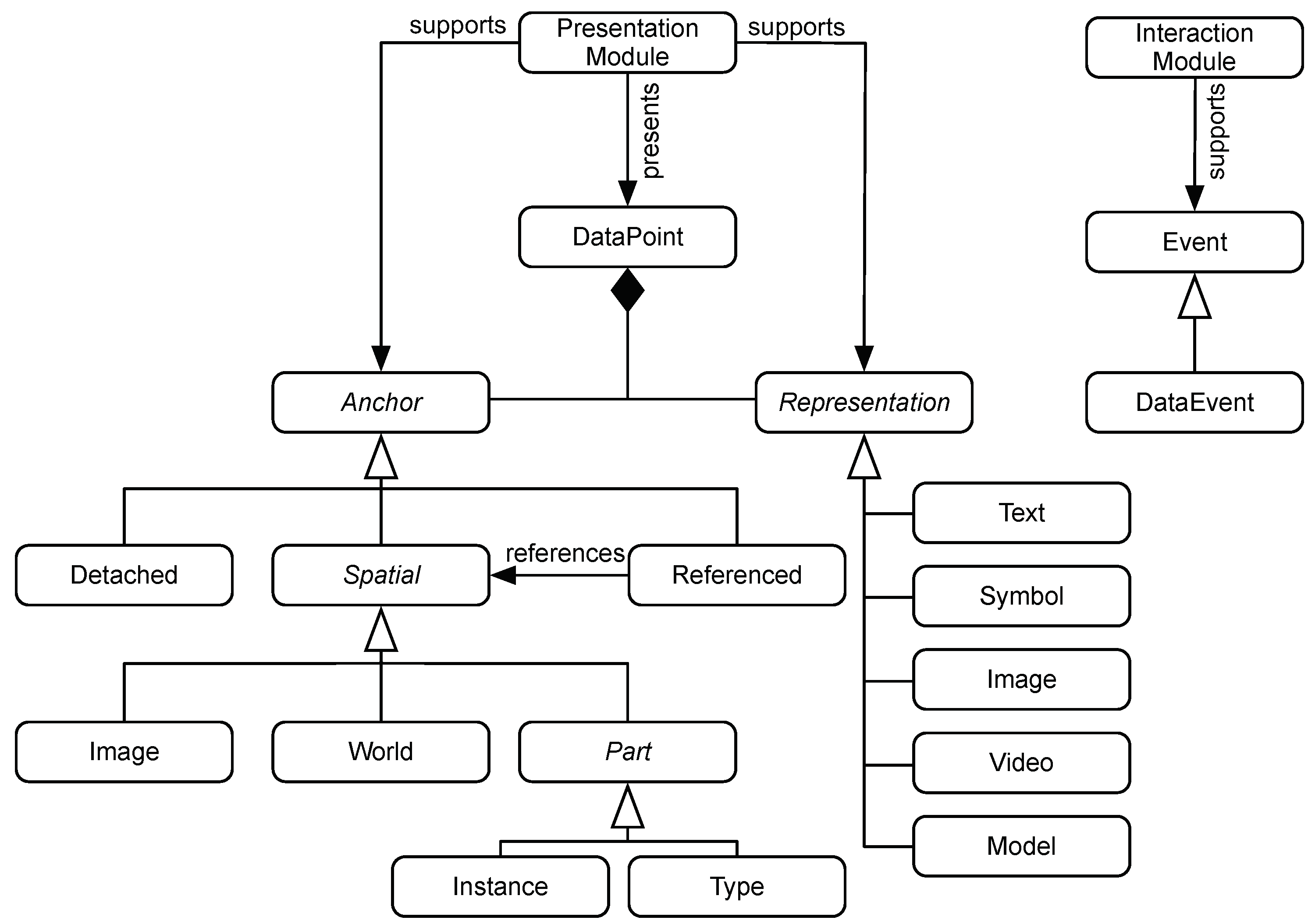
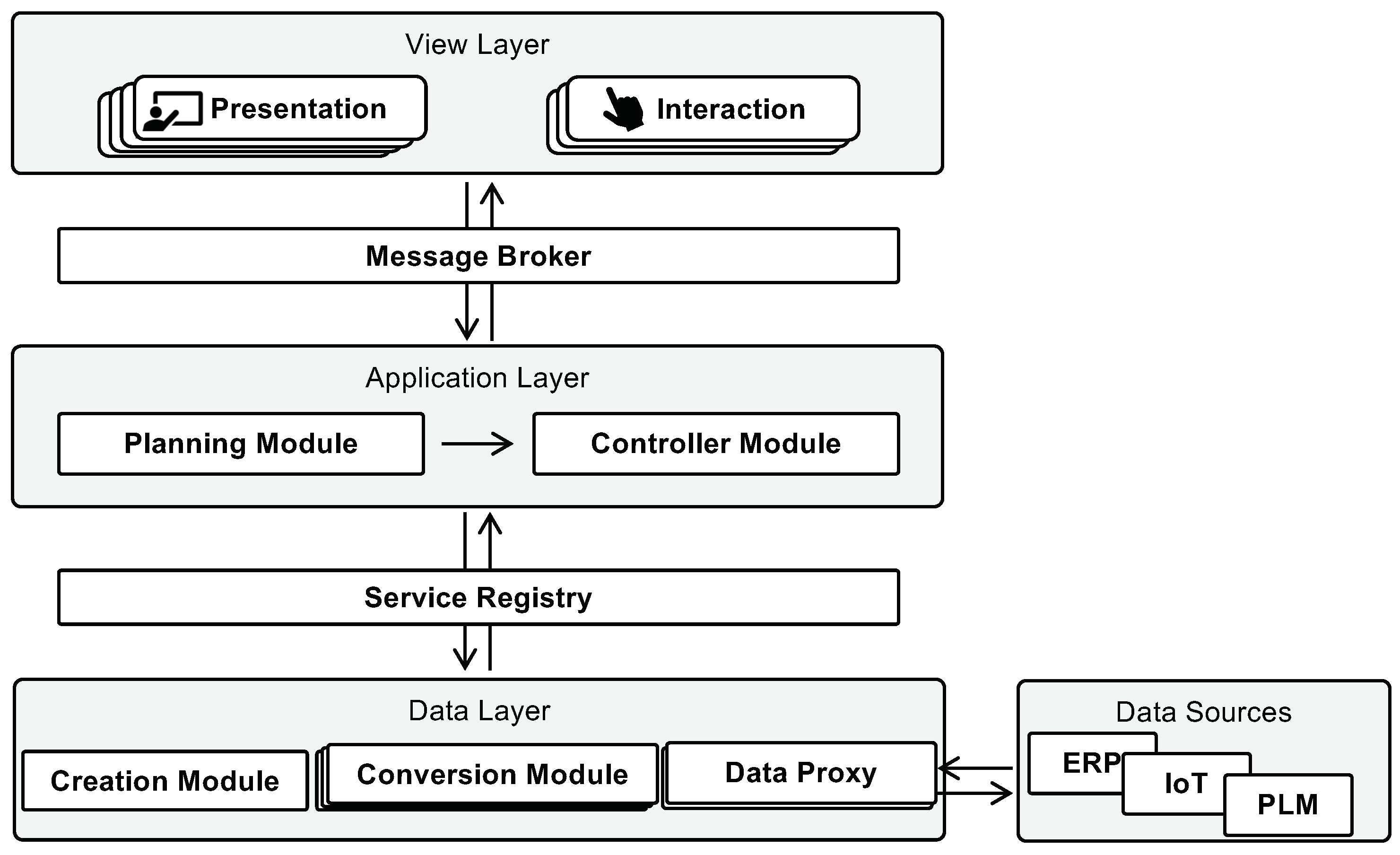
4.1. Modules and Data Model

We propose a data model for reusable modules in an IAR architecture (Figure 2). As discussed in the previous section, the main data model elements are anchors and data representations. The anchor describes the spatial position where information is presented. The representation describes how this information is conveyed to the users. The anchor may be detached, leaving it to the assistant system to decide on a good position to render the content. While many anchor points are possible for generic AR applications, industrial applications mostly attach information to parts, such as parts in a machine or storage. Additionally, information can be attached to an image, including QR and barcodes. As there exists no universally valid world coordinate system, world anchors are identified points or regions that are constant within the context of an individual application. This includes regions that are suitable for displaying certain content such as generic models or descriptions because they are easily readable by the user.
The data model does not describe how tracking such an anchor is accomplished. While there is a special image anchor type, tracking a specific part can also be realized by attaching a visual identifier such as a QR code on them. At the same time, tracking an object might be achieved using static positions, as long as the system can guarantee that objects always appear at this position.
The various ways data can be anchored to parts are shown in Figure 3. When content is not placed in relation to the environment but at some other position, it is described as detached. A common example is content that is displayed fixed to the screen instead of next to a part (Figure 3a). For example, detached text might be displayed at a fixed position within an HMD, without any spatial information at all. A spatial anchor is attached to some position in the world. In IAR applications, it is commonly defined through the position of some part (Figure 3b). Sometimes, this connection is not established directly. Instead, the anchor is defined in relation to the part, but not directly on top of it. For example, the position of a drill hole on a part is described by a fixed transform in relation to the part (Figure 3c). An anchor can be a reference to another spatial reference, implying a relationship, without rendering content on top of the anchor directly, such as referencing a tracked part with a symbol [51]. Referenced content only has a loose connection to the real world position. For example, a label might appear somewhere close to it (Figure 3d). This relationship would convey a distinct meaning, such as highlighting the specific part, but the symbol would not be rendered directly on top of the anchor [50]. Finally, one distinguishes content that is placed at a specific object (Figure 3e) or describes the position of an object type (Figure 3f). For example, a user should focus on either a single screw or a box containing more screws of a certain type.
Data representations follow the classification by Gattullo et al. [39]. However, as this data model describes required capabilities of output systems, some categories are combined. The simplest way of conveying information is by text. This can be rendered in 2D or 3D depending on the system, preference of the user and the anchor the data point uses. Symbols are graphical elements that convey a meaning through some standardized name, such as safety symbols. However, this also includes 3D content, such as a set of predefined arrows or tools. Whether a system uses 2D or 3D symbols is again an implementation detail of the displaying system. Images include technical drawings and photographs since there is no relevant difference when displaying them. Videos are typically short clips or recordings of a work step. Finally, there is no distinction made between auxiliary models and product models. All models that cannot be described through the generic symbol type are downloaded from a data source and displayed.
With this data model, the capabilities of the individual modules are described. Presentation modules are characterized by their supported anchor and representation types. A pick-to-light system is able to support part anchors through LEDs at storage boxes, but no representations. A monitor, on the other hand, does not support any spatial anchors, but is able to present text, images and videos. Together, these two modules present spatial information similar to other IAR applications. All-in-one solutions, such as HMDs, can offer a range of different capabilities across multiple distinct modules. They are able to present 2D and 3D information. Through various tracking techniques, they can also present content at different anchors. Interaction modules are characterized by the events they support. Some, such as a physical button, might support a single event, e.g., to proceed to the next step. Others might collect additional information, for example, a measurement result as part of a quality check.
Content is described in a generic state machine. A single execution of the use-case, such as assembling a product or a service task, is broken down into a series of distinct states. Every state is linked to a series of data points visible to the user while the state is active. States correspond to individual tasks in execution and control tasks. For inform and plan use-cases, the states may describe the different possible information objects or configuration options available. The user must be able to interact with the state machine by executing state transitions. This is done manually by the worker or automatically. The worker selects a specific work step or clicks a button. Smart systems detect when a tool is grabbed or when an error was detected in the performed work automatically.
Based on these assumptions, an IAR architecture is developed. Individual components are reusable and expandable and the application logic is strictly separated from both input and output systems that are the connection to the end user, as well as from the source data. Building on top of prior works [29], the individual components are developed as stand-alone modules that can be composed together into complex IAR applications.
The suggested variety of modules is shown in Figure 4. The view layer is separated into multiple presentation and interaction modules. The application layer is divided into a planning module and a controller. The controller module executes the application-specific logic and a system-monitoring component where other components register availability and capabilities. Before the system is used by a worker, a planning module is responsible for importing work plan data and converting them into a standardized format to be executed by the controller. This conversion already considers the available capabilities based on available components in the system’s monitoring module.
The application controller executes a state machine with a given start and zero and more end states. For every state, data are forwarded to the available representation components, while the interaction components can trigger transitions based on their associated events. Such state machines are created based on the use-case-specific input data, such as a work plan or assembly instructions, in the planning module. Before the overall system is used, the required representations and events are used to verify that connected components can display the desired content. They are then dynamically selected based on their capabilities and the requirements enforced by the content. Some presentation components might only support certain data representations, such as text, image or 3D formats. Content can therefore be converted to different formats or different representations, for example, preparing a 2D rendered image from a 3D model. Additionally, the supported tracking and anchor information needs to be adjusted for a given use-case, for example, by initializing object positions. This can either be done automatically based on assembly models, where the whole object might be tracked and the position of an individual part is calculated or manual, e.g., by describing the content of storage places. When the overall system supports all events and data representations, it can support the user in the given use-case. Because of the strict division between application layer and implementation of presentation and interaction components, they can easily be composed together or expanded to support different tasks.

4.2. Content Preparation

The overarching process of creating a use-case-specific IAR application from the general architecture is presented in Figure 5. In the figure, steps that require manual operator input are displayed in gray.
As a first step, the data are prepared based on optional source data, such as work plans or assembly instructions. Because this content creation often cannot happen fully automatically, an operator might need to get involved. Sometimes, it is possible to add and register additional anchors based on operator input, for example, by manually assigning a position or image to describe an anchor point.
In a next step, the actual content is converted so that the chosen subsystems can present it. This includes changing formats, such as converting CAD models into tessellated 3D data or changing the format of an image. This can also include transforming data from one data type into another. For example, a 3D model might be rendered into a 2D image when a system cannot display 3D content. This happens dynamically based on the described capabilities by the output systems and registered data conversion services.

4.3. Application Planning
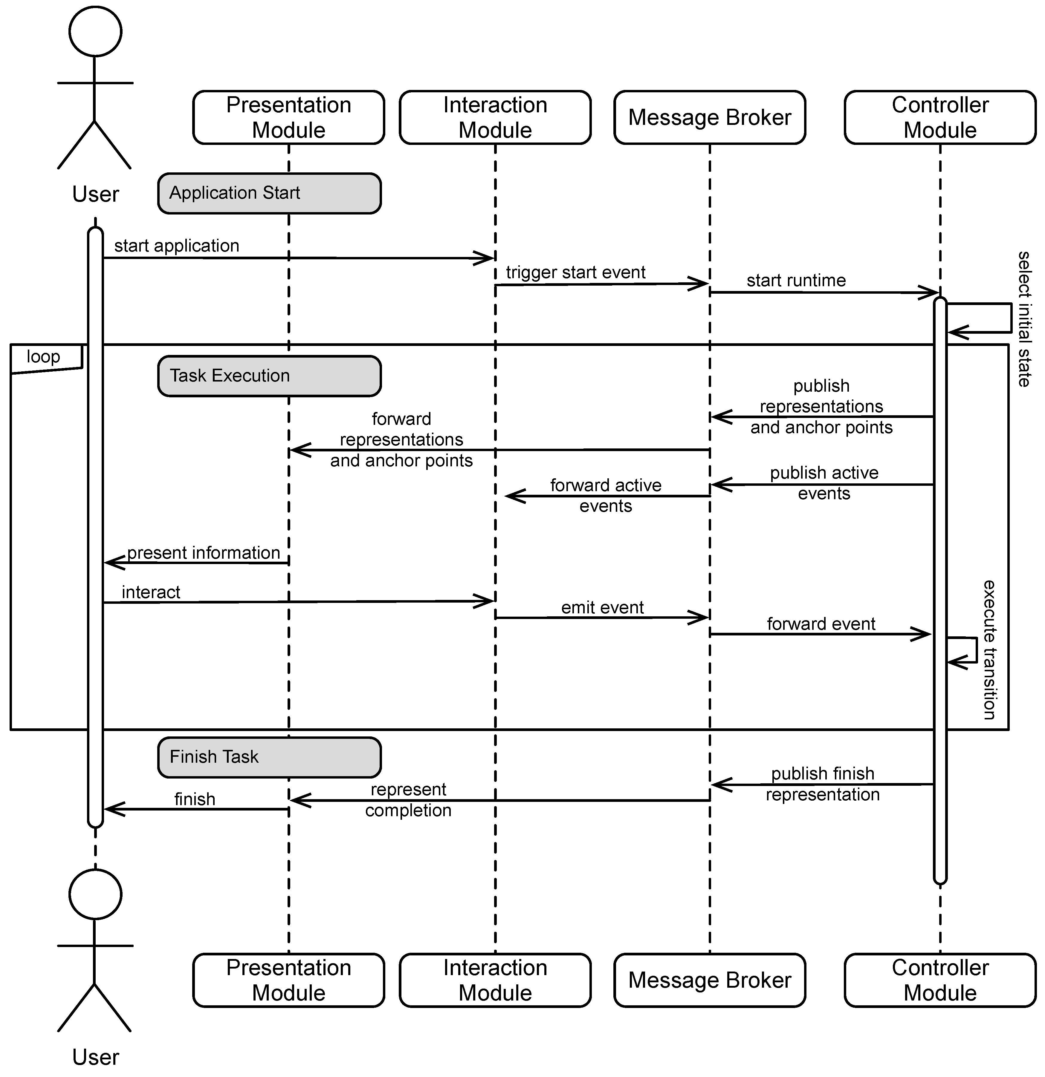
When a system is composed out of individual subsystems, several steps are taken by the application-planning module to ensure the system can present the desired content before the sequence shown in Figure 6. The content was created in the form of the state machine described above. From the necessary anchors, representations and events, the overall capabilities of the system are described.
All modules register their availability and capability by publishing through a central status topic together with a self-assigned unique identifier (Registering Capabilities). This message is sent with the MQTT “retained” flag [56], so that the controller is notified of all available components. During initial connection to the broker, the components set a “will” [56] to mark them as unavailable to the controller. This will is sent by the broker after an ungraceful disconnect by the components, e.g., in cases of an unexpected failure or network interruption.
Through the MQTT protocol, the application-planning module is notified as soon as the available modules or their capabilities change. It then starts the Anchor Definition phase. In a first step, it checks if all necessary anchor points are each supported by at least one interaction module. If some anchors are unsupported, the planning module publishes this module. Presentation modules that support operator customization can use this information to expand their capabilities to support the necessary anchors. For example, a presentation module capable of object tracking might be added to the system to detect the required part.
When all required anchors are available, the application-planning module automatically triggers representation conversions and transformations and selects the relevant modules used in every state. This includes tasks such as generating 2D renderings from 3D model files for presenting them in the projection module or converting file formats (Content Conversion). After this step is completed, the planning module verifies that the overall system capabilities match the requirements of the content (Finalize Planning). If not, the operator might need to add additional modules to the system. When all requirements have been met, the planned content is forwarded to the controller.
If the overall system consisting of supported anchors and representations is incapable of displaying the content plan, an operator needs to expand the system. This can mean implementing new functionality into existing subsystems or registering altogether new subsystems can be exchanged and expanded easily. As the controller module sends data points to all presentation modules with the required capabilities, new modules can be added at runtime. Similarly, the broker forwards all events emitted by new interaction modules. They, too, can be added without further customization, as long as the events correspond to known transitions in the controller module’s state machine.

4.4. Task Execution

An MQTT broker is used as the central message service. The concept makes use of the topic structure of the MQTT protocol to ensure only relevant data are forwarded to the appropriate modules. In particular, the topics for sending data points include the anchor and representation format needed. By using wildcard subscriptions, only modules capable of supporting the specified data points receive the data. The controller module can therefore publish data points, while the MQTT protocol is responsible for selecting relevant participants for such messages. The message flow between the application layer, the view layer with its interaction and presentation modules and the user is visualized in the sequence diagram (Figure 7).
The controller module is responsible for executing the state machine. Every state has several data points associated, which are a combination of a representation, such as an animation, a model or just some text, together with an anchor point. These are forwarded through the message broker to presentation components. Through the chosen MQTT topics, only components capable of presenting the combination of anchor point and representation receive the data that should be shown.
The controller module itself subscribes to all incoming events and then maps them to state transitions. An incoming event therefore triggers a transition to a new state, in which new data points are shown to the user. The controller also sends a deactivation command to interaction modules whose events are unsupported in the current state because there are no outgoing transitions associated with those. This is then presented in the interaction modules, for example by turning off LEDs inside hardware buttons or hiding buttons from a projected user interface.
The data points are usually known before the worker starts the supported process. This means that data conversion and preparation is already done during the application-planning phase. However, certain use-cases might require dynamic data, such as IoT or measurement results. The controller is therefore also capable of querying dynamic data from source systems and forwarding those to representation components. The task ends when a final state is reached in the state machine. This state usually includes a special information object informing the worker that the task is completed.

5. Prototypical Implementation of a Test Case

To evaluate the architecture, two IAR systems have been composed out of prototypical implementations of sample modules. As a use-case, a simple assembly process was selected. First, required guidance is identified. For a given work step, the worker needs to find and grab the required parts from small storage containers. Then, they need to add them correctly to the assembly. One important aspect of the IAR application is therefore to provide the worker with the necessary spatial information to make picking correct parts faster and more reliable. Other information, such as finding the correct assembly position, might also be advantageous. Other instructions can be conveyed by descriptions, images and videos that appear detached. Required anchor types are therefore part anchors for the storage containers. Referenced anchors are used to highlight the target position of the parts. The IAR system must present assembly instructions in the form of texts and images. Support for 3D content and animations is optional. The worker interacts with the system by choosing the next and previous assembly step. Optionally, a system might verify that a part has been selected from a correct storage container.

5.1. Identification of System Module Capabilities

To fulfil the given requirements and show the modularity of the architecture, two different support systems are composed. First, a traditional pick-to-light system where assembly instructions are presented on a monitor. While this setup does not strictly qualify as an IAR system, it nonetheless can be composed of the same modules in the explained architecture. The second setup is a projection-based in situ IAR application. Here it is assumed that the storage containers are placed on the workbench. The system projects both assembly instructions and location hints on top of the workbench, while a worker is able to control the setup through a time-of-flight depth sensor. The developed modules are presented in Table 1 and Table 2.

5.2. Prototypical IAR Systems

As discussed earlier, two prototypical IAR systems were composed out of the developed modules. They are presented in Figure 8. The pick-to-light system uses the monitor module and the pick-to-light module to guide the user to the correct parts. The monitor displays the needed assembly steps. Here, the actual assembly is still unsupported. The resulting system therefore only supports a medium level of support. For interaction with the system, the hardware button module provides two buttons. One is tied to a next event that proceeds to the next assembly step. With the other button, the user can go back to the previous step. Both the pick-to-light module and the hardware buttons use microcontrollers that connect to the MQTT broker over a wireless connection. While this setup is not suitable for industrial contexts, it was sufficient for the prototype.
Data for the system were created manually. A step in the runtime corresponds to a step in the assembly sequence. Each step references the anchor for the required parts as well as descriptions and images to describe the procedure. These are presented on the monitor. The individual states are only connected through transitions to the next and previous state.
The in situ IAR system uses the projector module as a presentation module. The setup consists of a projector and a depth sensor that are controlled through an application in the Unity Game Engine. It offers two modules to the overall system. On the one hand, the projector acts as a presentation module capable of displaying two-dimensional content. On the other hand, the combination of projector and depth sensor provides an interaction module that offers a virtual button. They are also projected on the surface, while the depth sensor senses when a hand hovers directly over them for a short time period. Additionally, the interaction module is capable of registering when a hand hovers over one of the storage containers. This results in a message when a part was taken from an unexpected container. The connection between the containers and the parts in them is made manually by an operator in the composition phase.

5.3. Expanding Existing Modules

In this default configuration, the runtime supports most use-cases that are converted to the required state-based representation. It does not need support for certain anchor types or data representations because it only forwards the information described in the prepared state machine. Similarly, it implicitly supports all kinds of events present in the state machine as long as at least one interaction component supports it. For more complex use-cases, however, some customization of the runtime might be needed. The runtime therefore offers various extension points. It is possible to change the reaction for incoming events and change the mapping to the associated transitions. Because the used MQTT messages could contain a payload, a custom extension might read the payload of such an event and forward it to a monitoring and reporting system. This is useful for supporting quality control tasks, where the measured quality data can be forwarded from an interaction component as a message with the measured values inside the message payload.

6. Discussion

The overall architecture was successfully implemented for both a traditional pick-to-light assembly station and an in situ projection setup. The setup could easily be expanded without making any changes to data import and conversion or the controller module by replacing the pick-to-light presentation components with similar functionalities in the projection setup. This shows the advantages of such an architecture compared to common all-in-one implementations. By building IAR systems on top of a modular architecture, developers have the chance to more easily adapt them to changing requirements or different use-cases. Investments in available components are therefore more future-proof because they can later be reused and expanded in different configurations for different tasks.
For the presented assembly station, the capabilities of the projection setup will be supplemented with the possibility of automatically checking the correct assembly of the overall parts using AI-based parts recognition. While the implementation details of such a system are outside the scope of this paper, it can be easily integrated in the IAR system by creating a new interaction component. This emits events for correct and incorrect assembly and updates the state machine accordingly. Because of the clearly defined interfaces between the components, these can also be supplied by multiple vendors. Smaller companies could then compose the modules together to better support their use-case.
The major drawback of such an architecture is the added complexity. The benefits of easier adaption and modularity only become apparent when the configuration and use-cases support change when using the support system. For applications that support numerous users, the extra effort required for specially developed software systems might be justified. For smaller companies, however, the presented modular architecture offers an easier and more future-proof introduction to IAR systems than trying to use custom-built software or trying to adapt a one-size-fits-all software solution to their special needs. The approach presented in this paper also allows new business models around new modules. Sensor manufactures could provide pre-built capabilities, such as an image sensor that compares an as-is state to an operator-defined targeted state. Such an interaction module can then be used by companies to further expand the existing assistant system to their needs.

7. Conclusions

This paper presents a novel architecture for IAR applications. To answer RQ1, modules in the view layer are separated into those with presentation and interaction capabilities. Based on the literature review, presentation modules are described based on their supported anchors as the position in space they can highlight and the data representation type they can present, such as models, images or texts. Interaction modules are sufficiently described by the events they trigger.
Section 4 describes how an operator works with the application layer to compose a system out of the individual modules (RQ2). It is shown that while some tasks can be automated, e.g., the conversion of data into different formats, the operator uses their insights and knowledge of the environment to configure the individual models. The controller then sends structured messages to the view layer modules through the MQTT protocol to ensure that the appropriate information is forwarded to each module. Finally, an example is provided to show how a single use-case can be supported with different modalities and how the capability of such systems can be expanded with additional modules (RQ3).
In further works, the architecture needs to be validated in industrial use-cases. Furthermore, the formal processes of integration of new functionality in newly defined modules need to be further described.

Author Contributions

Conceptualization, D.G., M.N., J.L.S. and M.W.; software, J.L.S.; investigation, J.L.S.; writing—original draft preparation, J.L.S.; writing—review and editing, D.G., M.N., J.L.S. and M.W.; supervision, D.G. All authors have read and agreed to the published version of the manuscript.

Funding

This research received no external funding.

Institutional Review Board Statement

Not applicable.

Informed Consent Statement

Not applicable.

Data Availability Statement

Data sharing not applicable.

Acknowledgments

The authors would like to thank Lasse Christian Bömkes for his work on the software implementation.

Conflicts of Interest

The authors declare no conflict of interest.

References

  1. Fite-Georgel, P. Is there a reality in Industrial Augmented Reality? In Proceedings of the International Symposium on Mixed and Augmented Reality, Basel, Switzerland, 26–29 October 2011; IEEE: Piscataway, NJ, USA, 2011. [Google Scholar]
  2. Wang, X.; Ong, S.K.; Nee, A.Y.C. A comprehensive survey of augmented reality assembly research. Adv. Manuf. 2016, 4, 1–22. [Google Scholar] [CrossRef]
  3. Fernández del Amo, I.; Erkoyuncu, J.A.; Roy, R.; Palmarini, R.; Onoufriou, D. A systematic review of Augmented Reality content-related techniques for knowledge transfer in maintenance applications. Comput. Ind. 2018, 103, 47–71. [Google Scholar] [CrossRef]
  4. Röltgen, D.; Dumitrescu, R. Classification of industrial Augmented Reality use cases. Procedia CIRP 2020, 91, 93–100. [Google Scholar] [CrossRef]
  5. Ludwig, B. Planbasierte Mensch-Maschine-Interaktion in multimodalen Assistenzsystemen; Springer: Berlin/Heidelberg, Germany, 2015. [Google Scholar] [CrossRef]
  6. Funk, M.; Bächler, A.; Bächler, L.; Kosch, T.; Heidenreich, T.; Schmidt, A. Working with Augmented Reality? In Proceedings of the 10th International Conference on PErvasive Technologies Related to Assistive Environments, Rhodes, Greece, 21–23 June 2017; pp. 222–229. [Google Scholar]
  7. Loizeau, Q.; Danglade, F.; Ababsa, F.; Merienne, F. Evaluating added value of Augmented Reality to assist aeronautical Maintenance Workers—Experimentation on On-field Use Case. In Virtual Reality and Augmented Reality. EuroVR 2019; Bourdot, P., Interrante, V., Nedel, L., Magnenat-Thalmann, N., Zachmann, G., Eds.; Lecture Notes in Computer Science; Springer International Publishing: Cham, Switzerland, 2019; Volume 11883, pp. 151–169. [Google Scholar] [CrossRef] [Green Version]
  8. Masood, T.; Egger, J. Adopting augmented reality in the age of industrial digitalisation. Comput. Ind. 2020, 115, 103112. [Google Scholar] [CrossRef]
  9. Bosch, T.; van Rhijn, G.; Krause, F.; Könemann, R.; Wilschut, E.S.; de Looze, M. Spatial augmented reality. In Proceedings of the 13th ACM International Conference on PErvasive Technologies Related to Assistive Environments, Corfu, Greece, 30 June–3 July 2020. [Google Scholar] [CrossRef]
  10. Palmarini, R.; Erkoyuncu, J.A.; Roy, R.; Torabmostaedi, H. A Systematic Review of Augmented Reality applications in Maintenance. Robot. -Comput.-Integr. Manuf. 2018, 49, 215–228. [Google Scholar] [CrossRef] [Green Version]
  11. Geng, J.; Song, X.; Pan, Y.; Tang, J.; Liu, Y.; Zhao, D.; Ma, Y. A systematic design method of adaptive augmented reality work instruction for complex industrial operations. Comput. Ind. 2020, 119, 103229. [Google Scholar] [CrossRef]
  12. Huang, G.; Qian, X.; Wang, T.; Patel, F.; Sreeram, M.; Cao, Y.; Ramani, K.; Quinn, A.J. AdapTutAR: An adaptive tutoring system for machine tasks in Augmented Reality. In Proceedings of the 2021 CHI Conference on Human Factors in Computing Systems, Yokohama, Japan, 8–13 May 2021; Association for Computing Machinery: New York, NY, USA, 2021. [Google Scholar] [CrossRef]
  13. Siewert, J.L.; Neges, M.; Gerhard, D. Ein Klassifizierungssystem für Industrielle Augmented Reality Anwendungen; TUDpress: Dresden, Germany, 2021; pp. 401–416. [Google Scholar]
  14. Siewert, J.L.; Wolf, M.; Böhm, B.; Thienhaus, S. Usability Study for an Augmented Reality Content Management System. In Cross Reality and Data Science in Engineering; Springer: Berlin, Germany, 2020; pp. 274–287. [Google Scholar] [CrossRef]
  15. Büttner, S.; Prilla, M.; Röcker, C. Augmented Reality Training for Industrial Assembly Work - Are Projection-based AR Assistive Systems an Appropriate Tool for Assembly Training? In Proceedings of the 2020 CHI Conference on Human Factors in Computing Systems, Honolulu, HI, USA, 25–30 April 2020; pp. 1–12. [Google Scholar] [CrossRef]
  16. Mourtzis, D.; Vlachou, A.; Zogopoulos, V. Cloud-Based Augmented Reality Remote Maintenance Through Shop-Floor Monitoring: A Product-Service System Approach. J. Manuf. Sci. Eng. 2017, 139, 061011. [Google Scholar] [CrossRef]
  17. Brice, D.; Rafferty, K.; McLoone, S. AugmenTech: The usability evaluation of an AR system for maintenance in industry. In Augmented Reality, Virtual Reality and Computer Graphics. AVR 2020; Lecture Notes in Computer Science; Springer: Cham, Switzerland, 2020; Volume 12243, pp. 284–303. [Google Scholar] [CrossRef]
  18. Siewert, J.L.; Vogt, O.; Wolf, M.; Gerhard, D.; Bükrü, S.F. Implementation of the Asset Administration Shell Concept to Industrial Augmented Reality Applications; Springer: Cham, Switzerland, 2023; pp. 255–266. [Google Scholar] [CrossRef]
  19. Wolf, M.; Siewert, J.L.; Vogt, O.; Gerhard, D. Augmented Reality-Assisted Quality Control Based on Asset Administration Shells for Concrete Elements. In Product Lifecycle Management. PLM in Transition Times: The Place of Humans and Transformative Technologies; Noël, F., Nyffenegger, F., Rivest, L., Bouras, A., Eds.; Springer Nature: Cham, Switzerland, 2023; pp. 358–367. [Google Scholar] [CrossRef]
  20. Szajna, A.; Stryjski, R.; Woźniak, W.; Chamier-Gliszczyński, N.; Królikowski, T. The Production Quality Control Process, Enhanced with Augmented Reality Glasses and the New Generation Computing Support System. Procedia Comput. Sci. 2020, 176, 3618–3625. [Google Scholar] [CrossRef]
  21. Schwerdtfeger, B.; Pustka, D.; Hofhauser, A.; Klinker, G. Using Laser Projectors for Augmented Reality. In Proceedings of the 2008 ACM Symposium on Virtual Reality Software and Technology, VRST ’08, Bordeaux, France, 27–29 October 2008; pp. 134–137. [Google Scholar] [CrossRef]
  22. Segovia, D.; Mendoza, M.; Mendoza, E.; González, E. Augmented Reality as a Tool for Production and Quality Monitoring. Procedia Comput. Sci. 2015, 75, 291–300. [Google Scholar] [CrossRef] [Green Version]
  23. Coscetti, S.; Moroni, D.; Pieri, G.; Tampucci, M. Factory maintenance application using Augmented Reality. In Proceedings of the 3rd International Conference on Applications of Intelligent Systems, Las Palmas de Gran Canaria, Spain, 7–9 January 2020. [Google Scholar] [CrossRef]
  24. Vogel, C.; Schulenburg, E.; Elkmann, N. Projective- AR Assistance System for shared Human-Robot Workplaces in Industrial Applications. In Proceedings of the 2020 25th IEEE International Conference on Emerging Technologies and Factory Automation (ETFA), Vienna, Austria, 8–11 September 2020; pp. 1259–1262. [Google Scholar] [CrossRef]
  25. Pentenrieder, K.; Bade, C.; Doil, F.; Meier, P. Augmented Reality-based factory planning—An application tailored to industrial needs. In Proceedings of the 2007 6th IEEE and ACM International Symposium on Mixed and Augmented Reality, Nara, Japan, 13–16 November 2007; IEEE: Piscataway, NJ, USA, 2007; pp. 1–9. [Google Scholar]
  26. Herr, D.; Reinhardt, J.; Reina, G.; Krüger, R.; Ferrari, R.V.; Ertl, T. Immersive modular factory layout planning using Augmented Reality. Procedia CIRP 2018, 72, 1112–1117. [Google Scholar] [CrossRef]
  27. Stadler, S.; Kain, K.; Giuliani, M.; Mirnig, N.; Stollnberger, G.; Tscheligi, M. Augmented reality for industrial robot programmers: Workload analysis for task-based, augmented reality-supported robot control. In Proceedings of the 2016 25th IEEE International Symposium on Robot and Human Interactive Communication (RO-MAN), New York, NY, USA, 26–31 August 2016; pp. 179–184. [Google Scholar] [CrossRef] [Green Version]
  28. Ong, S.K.; Yew, A.; Thanigaivel, N.K.; Nee, A. Augmented reality-assisted robot programming system for industrial applications. Robot. Comput.-Integr. Manuf. 2020, 61, 101820. [Google Scholar] [CrossRef]
  29. MacWilliams, A.; Reicher, T.; Klinker, G.; Bruegge, B. Design Patterns for Augmented Reality Systems. In Proceedings of the International Workshop Exploring the Design and Engineering of Mixed Reality Systems (MIXER), Funchal, Portugal, 13 January 2004. [Google Scholar]
  30. Djordjevic, L.; Petrovic, N.; Tosic, M. Ontology based approach to development of augmented reality applications. In Proceedings of the 2019 27th Telecommunications Forum (TELFOR), Belgrade, Serbia, 26–27 November 2019; IEEE: Piscataway, NJ, USA, 2019; pp. 1–4. [Google Scholar] [CrossRef]
  31. Hervas, R.; Bravo, J.; Fontecha, J.; Villarreal, V. Achieving adaptive Augmented Reality through ontological context-awareness applied to AAL scenarios. J. Univers. Comput. Sci. 2013, 19, 1334–1349. [Google Scholar]
  32. Abawi, D.F.; Dörner, R.; Grimm, P. A component-based authoring environment for creating multimedia-rich Mixed Reality. In Proceedings of the EUROGRAPHICS Workshop on Multimedia, Ninjing, China, 27–28 October 2004; Correia, N., Jorge, J., Chambel, T., Pan, Z., Eds.; Eurographics Association: Aire-la-Ville, Switzerland, 2004; pp. 31–40. [Google Scholar]
  33. Kuster, T.; Masuch, N.; Fahndrich, J.; Tschirner-Vinke, G.; Taschner, J.; Specker, M.; Iben, H.; Baumann, H.; Schmid, F.; Stocklein, J.; et al. A distributed architecture for modular and dynamic Augmented Reality processes. In Proceedings of the 2019 IEEE 17th International Conference on Industrial Informatics (INDIN), Helsinki, Finland, 22–25 July 2019; IEEE: Piscataway, NJ, USA, 2019. [Google Scholar] [CrossRef]
  34. Gramberg, T.; Kruger, K.; Niemann, J. Augmented Reality for operators in smart manufacturing environments: A case study implementation. In Smart, Sustainable Manufacturing in an Ever-Changing World; von Leipzig, K., Sacks, N., Mc Clelland, M., Eds.; Springer International Publishing: Cham, Switzerland, 2023; pp. 401–413. [Google Scholar] [CrossRef]
  35. Azuma, R.T. A survey of augmented reality. Presence Teleoperators Virtual Environ. 1997, 6, 355–385. [Google Scholar] [CrossRef]
  36. Lechner, M. ARML 2.0 in the context of existing AR data formats. In Proceedings of the 2013 6th Workshop on Software Engineering and Architectures for Realtime Interactive Systems (SEARIS), Orlando, FL, USA, 17 March 2013; IEEE: Piscataway, NJ, USA, 2013. [Google Scholar] [CrossRef]
  37. Peters, M.D.; Godfrey, C.M.; Khalil, H.; McInerney, P.; Parker, D.; Soares, C.B. Guidance for conducting systematic scoping reviews. Int. J. Evid.-Based Healthc. 2015, 13, 141–146. [Google Scholar] [CrossRef] [Green Version]
  38. Garcia-Pereira, I.; Gimeno, J.; Morillo, P.; Casanova-Salas, P. A Taxonomy of Augmented Reality Annotations. In Proceedings of the 15Th International Joint Conference on Computer Vision, Imaging and Computer Graphics Theory and Applications, Valletta, Malta, 27–29 February 2020; Bouatouch, K., Sousa, A., Braz, J., Eds.; SciTePress: Setúbal, Portugal, 2020; Volume 1, pp. 412–419. [Google Scholar] [CrossRef]
  39. Gattullo, M.; Evangelista, A.; Uva, A.E.; Fiorentino, M.; Gabbard, J.L. What, How and Why are visual assets used in Industrial Augmented Reality? A systematic review and classification in maintenance, assembly and training (from 1997 to 2019). IEEE Trans. Vis. Comput. Graph. 2022, 28, 1443–1456. [Google Scholar] [CrossRef] [PubMed]
  40. Li, W.; Nee, A.; Ong, S. A state-of-the-art review of augmented reality in engineering analysis and simulation. Multimodal Technol. Interact. 2017, 1, 17. [Google Scholar] [CrossRef] [Green Version]
  41. Müller, T.; Dauenhauer, R. A Taxonomy for Information Linking in Augmented Reality. In Augmented Reality, Virtual Reality and Computer Graphics, Pt I; DePaolis, L., Mongelli, A., Eds.; Lecture Notes in Computer Science; Springer: Cham, Switzerland, 2016; Volume 9768, pp. 368–387. [Google Scholar] [CrossRef]
  42. Phaijit, O.; Obaid, M.; Sammut, C.; Johal, W. A Taxonomy of Functional Augmented Reality for Human-Robot Interaction. In Proceedings of the 2022 17th ACM/IEEE International Conference on Human-Robot Interaction (HRI ‘22), Sapporo, Japan, 7–10 March 2022; pp. 294–303. [Google Scholar] [CrossRef]
  43. Runji, J.M.; Lee, Y.J.; Chu, C.H. Systematic Literature Review on Augmented Reality-Based Maintenance Applications in Manufacturing Centered on Operator Needs. Int. J. Precis. Eng.-Manuf.-Green Technol. 2023, 10, 567–585. [Google Scholar] [CrossRef]
  44. Suzuki, R.; Karim, A.; Xia, T.; Hedayati, H.; Marquardt, N. Augmented Reality and Robotics: A Survey and Taxonomy for AR-enhanced Human-Robot Interaction and Robotic Interfaces. In Proceedings of the 2022 Chi Conference on Human Factors in Computing Systems (CHI’ 22), New Orleans, LA, USA, 29 April–5 May 2022. [Google Scholar] [CrossRef]
  45. Tobiskova, N.; Malmskold, L.; Pederson, T. Multimodal Augmented Reality and Subtle Guidance for Industrial Assembly—A Survey and Ideation Method. In Virtual, Augmented and Mixed Reality: Applications in Education, Aviation and Industry, Pt Ii, Proceedings of the 14th International Conference, VAMR 2022, Held as Part of the 24th HCI International Conference, HCII 2022, Virtual Event, 26 June– 1 July 2022; Chen, J., Fragomeni, G., Eds.; Lecture Notes in Computer Science; Springer: Cham, Switzerland, 2022; Volume 13318, pp. 329–349. [Google Scholar] [CrossRef]
  46. Tönnis, M.; Plecher, D.A.; Klinker, G. Representing information—Classifying the Augmented Reality presentation space. Comput. Graph. 2013, 37, 997–1011. [Google Scholar] [CrossRef]
  47. Woodward, J.; Ruiz, J. Analytic Review of Using Augmented Reality for Situational Awareness. IEEE Trans. Vis. Comput. Graph. 2023, 29, 2166–2183. [Google Scholar] [CrossRef]
  48. Zollmann, S.; Langlotz, T.; Grasset, R.; Lo, W.H.; Mori, S.; Regenbrecht, H. Visualization Techniques in Augmented Reality: A Taxonomy, Methods and Patterns. IEEE Trans. Vis. Comput. Graph. 2021, 27, 3808–3825. [Google Scholar] [CrossRef]
  49. Keil, J.; Schmitt, F.; Engelke, T.; Graf, H.; Olbrich, M. Augmented Reality Views: Discussing the Utility of Visual Elements by Mediation Means in Industrial AR from a Design Perspective; Lecture Notes in Computer Science; Springer: Cham, Switzerland, 2018; pp. 298–312. [Google Scholar] [CrossRef]
  50. Müller, T. Challenges in representing information with augmented reality to support manual procedural tasks. Aims Electron. Electr. Eng. 2019, 3, 71–97. [Google Scholar] [CrossRef]
  51. Tönnis, M.; Plecher, D.A. Presentation Principles in Augmented Reality Classification and Categorization Guidelines; Technical Report TUM-I111; Technische Universität München: München, Germany, 2011. [Google Scholar]
  52. Wither, J.; DiVerdi, S.; Höllerer, T. Annotation in outdoor augmented reality. Comput. Graph. 2009, 33, 679–689. [Google Scholar] [CrossRef]
  53. Wang, J.; Feng, Y.; Zeng, C.; Li, S. An augmented reality based system for remote collaborative maintenance instruction of complex products. In Proceedings of the 2014 IEEE International Conference on Automation Science and Engineering (CASE), New Taipei, Taiwan, 18–22 August 2014; IEEE: Piscataway, NJ, USA, 2014. [Google Scholar] [CrossRef]
  54. Scurati, G.W.; Gattullo, M.; Fiorentino, M.; Ferrise, F.; Bordegoni, M.; Uva, A.E. Converting maintenance actions into standard symbols for Augmented Reality applications in Industry 4.0. Comput. Ind. 2018, 98, 68–79. [Google Scholar] [CrossRef]
  55. Rolim, C.; Schmalstieg, D.; Kalkofen, D.; Teichrieb, V. [POSTER] Design Guidelines for Generating Augmented Reality Instructions. In Proceedings of the 2015 IEEE International Symposium on Mixed and Augmented Reality, Fukuoka, Japan, 29 September–3 October 2015. [Google Scholar] [CrossRef]
  56. OASIS Open. MQTT Version 5.0. OASIS Standard. Available online: https://docs.oasis-open.org/mqtt/mqtt/v5.0/mqtt-v5.0.html (accessed on 26 June 2023).
Figure 1. Process of the Systematic Scoping Review.
Mti 07 00065 g001
Figure 2. Simplified data model of anchors and representations.
Mti 07 00065 g002
Figure 3. Common Anchor Types for IAR Applications.
Mti 07 00065 g003
Figure 4. System Overview with view layer, application layer, data layer and the modules connecting them.
Mti 07 00065 g004
Figure 5. Steps required for preparing a system.
Mti 07 00065 g005
Figure 6. Sequence diagram of the application-planning module.
Mti 07 00065 g006
Figure 7. Sequence diagram for the execution of the application.
Mti 07 00065 g007
Figure 8. The implemented Industrial Augmented Reality (IAR) prototypes based on the modular architecture.
Mti 07 00065 g008
Table 1. Implemented Presentation Modules and their capabilities.
ModuleAnchor TypesRepresentation TypesUsed in Example 1Used in Example 2
Pick-To-LightReferenced: Part *none
MonitorDetachedText
Image
Video
ProjectorDetachedText
Referenced: Part *Image
Part *Video
* Anchoring achieved through manual setup by the operator. ◦ indicate no, • indicate yes.
Table 2. Implemented Interaction Modules and their capabilities.
ModuleSupported EventsUsed in Example 1Used in Example 2
Hardware Button“next”
“previous”
Virtual Button“next”
“previous”
Storage Container RecognitionData Event (Container ID)
◦ indicate no, • indicate yes.
Disclaimer/Publisher’s Note: The statements, opinions and data contained in all publications are solely those of the individual author(s) and contributor(s) and not of MDPI and/or the editor(s). MDPI and/or the editor(s) disclaim responsibility for any injury to people or property resulting from any ideas, methods, instructions or products referred to in the content.

