1. Introduction
Fretting is a failure mode that occurs at the contact surfaces of two components subjected to low-amplitude oscillatory relative motions and fatigue loading. Fretting, combined with fatigue, can significantly reduce the lifespan of various mechanical components, including bearings, screw-type joints, bolted or dovetail joints, press-fitted shafts, couplings, and others. In gas turbine engines, fretting fatigue is especially prominent, occurring at the contact interfaces of the turbine blade roots, compressors dovetail joints, or fir-tree root joints in power turbines. Also, metal 3D printing has recently emerged as a transformative manufacturing technology. It offers significant advantages, such as eliminating the need for mold fabrication and enabling the production of geometrically complex components [
1]. The metal additive manufacturing technique provides remarkable versatility, enabling the cost-effective production of metal components that may otherwise be prohibitively expensive or infeasible to produce using conventional techniques [
2].
Given the critical importance of turbine components for reliable engine performance, this research aims to integrate material testing with design validation by evaluating the fretting fatigue life and damage characteristics of standard Ti-6Al-4V alloy specimens fabricated using additive manufacturing. By employing selective laser melting (SLM), a powder bed fusion technique, this study not only investigates fatigue performance under representative loading conditions but also derives design-relevant insights. These insights contribute to a more informed approach to the structural design of AM components in fatigue-critical applications. Furthermore, this study introduces a novel integration of experimental fretting fatigue results into a design-supportive fretting damage map, aiming to assist engineers in determining operational safety margins and optimizing design parameters for AM components under fretting-prone conditions. The following section reviews prior research, highlighting the need for experimentally grounded tools to guide design decisions in the context of fretting fatigue.
2. Literature Review
Farsha Abbasi et al. [
3] provided a comprehensive review of the effects of variable cyclic contact loading on the fretting fatigue behavior of various engineering components. Iyer and Mall [
4] conducted fretting fatigue tests for two types of contact surface geometries, including flat and cylindrical titanium alloy Ti-6Al-4V surfaces, under constant and two-level block remote bulk stresses. Under two-level block loading, the stress amplitude and high-cyclic fatigue (HCF) frequency of the applied load influenced the fretting fatigue life. Also, fracture topographies were drawn for the different test conditions. Furthermore, the impact of fretting pad geometry on crack initiation in Ti-6Al-4V was investigated in [
5], detailing crack location and orientation along the contact surface. In the study, finite element modeling (FEM) was utilized to simulate and compare fretting fatigue behavior in both low- and high-cycle fatigue regimes with experimental results. In [
6] a fracture mechanics approach was employed to develop a nonlinear integrated model for surface contacts, enabling the prediction of conditions under which small fretting-induced fatigue cracks are arrested. Studies on nickel- and titanium-based alloys, conducted using a specialized multiaxial fretting test machine, further advanced the understanding of fretting behavior [
7]. This research also developed a finite element contact model for multiaxial shakedown fatigue analysis, specifically applied to highly loaded blade–disk connections.
The influence of manufacturing techniques on fatigue life was investigated by Chan et al. [
8]. This study used scanning electron microscopy (SEM) to identify crack initiation sites of regular Ti-6Al-4V compared to that produced using other manufacturing techniques. Another study [
9] has further elucidated the fretting performance of Ti-6Al-4V produced via additive manufacturing (AM), particularly selective laser melting (SLM) or laser powder bed fusion (LPBF), in direct comparison with conventionally manufactured counterparts. Their results showed no statistically significant differences in wear track depth or fretting current between AM and traditional Ti-6Al-4V materials. Glodek et al. [
10] conducted the first dedicated fretting fatigue tests on LPBF-fabricated Ti-6Al-4V dovetail specimens, employing a purpose-built test apparatus and validated finite element model to replicate stick–slip conditions. Their findings revealed that while AM-Ti-6Al-4V exhibited enhanced crack propagation resistance relative to wrought material, it was more prone to fretting damage initiation. Together, these studies underscore the nuanced trade-offs between AM and conventional Ti-6Al-4V in fretting-related applications, emphasizing the need for design and life prediction frameworks that explicitly account for AM-induced microstructural features and degradation mechanisms.
In a different context, focusing on the influence of loading conditions rather than manufacturing routes, Huayang Zhang et al. [
11] investigated the impact of applied tangential force on the fretting fatigue life of tested specimens. The study examined crack initiation life, crack growth life, and total fatigue life using an extended finite element method (XFEM) combined with a cyclic cohesive damage model. Mario Lavella [
12] conducted fretting fatigue experiments of additively manufactured blades of the intermetallic alloy TiAl. The tests were performed at a specific loading frequency and high temperature to replicate real aircraft turbine operating conditions. Both analytical approaches and two-dimensional finite element (FE) analyses were employed to evaluate the stress distribution at the contact surfaces of the components. In [
13], several 3D contact geometries, including cylinder-on-plane and punch-on-plane configurations, were examined under different slip regimes to perform finite element numerical analysis. Moreover, this study investigated the fatigue damage of the Ti-6Al-4V alloy in the presence of fretting wear. Numerical simulations were conducted to analyze the effects of fatigue fretting, focusing on wear or fatigue crack initiation.
Resende Pereira et al. [
14] presented a finite element model of fretting fatigue for cylindrical contact interfaces and discussed aspects of fretting fatigue crack initiation, including crack location, orientation, and length. The study also provided experimental results and analytical solutions for the cylindrical contact model of fretting fatigue. Furthermore, additional aspects of fretting fatigue, including out-of-phase loading, cohesive zone modeling, wear effects, heterogeneity, and crystal orientation, were briefly reviewed. To complement simulation-based approaches, Egan [
15] reviewed recent innovations in design for additive manufacturing (DfAM), with particular emphasis on the integration of topology optimization and fatigue-informed simulation frameworks for the development of high-performance, material-efficient components. These strategies align well with contemporary modeling efforts that aim to connect microstructural characteristics with macro-scale mechanical constraints in fretting fatigue and contact interface applications. In [
16], a fretting fatigue crack initiation life model was developed based on slip amplitude as a macroscopic feature of the contact interfaces. A damage parameter combined with a damage severity factor was used to predict crack initiation life. Additionally, a series of fretting fatigue tests were conducted to evaluate the accuracy of the proposed prediction model. Furthermore, a plastic fretting fatigue life prediction model was established in [
17] based on standard structural contact theory. This model was evaluated by comparing cyclic load maximum stress values obtained through experimental studies and FEM simulation.
Lingfeng Wang et al. [
18] explored the application of additive manufacturing (AM) in the production and repair of aero-engine titanium alloy blades. Additionally, the study summarized key factors influencing the fatigue performance of AM titanium alloys and discussed the fatigue mechanism, research methods, and process optimizations of AM manufactured components. In [
19], the fatigue life of two-layered Ti-6Al-4V alloys, composed of an additively manufactured layer and a conventional wrought layer, was investigated under constant amplitude loading to evaluate the effect of post-heat treatment on fatigue life. Grzegorz Glodek et al. [
20] performed a tribo-mechanical fretting fatigue analysis of additively manufactured Ti-6Al-4V under cyclic loading to model the dovetail joint connection between a turbine blade and disk. A dedicated test apparatus was used to assess the performance of the 3D-printed material in comparison to its wrought counterpart. In addition, a finite element model was employed to analyze stress distribution at the contact surfaces.
The aim of the present study is to investigate the fretting fatigue behavior of Ti-6Al-4V alloy fabricated by selective laser melting (SLM), with a particular focus on the influence of axial stress and contact load on fatigue life and damage mechanisms. Standard axial fatigue tests, aligned with ASTM E466, were conducted under varying loading conditions, followed by post mortem damage analysis using scanning electron microscopy (SEM) to identify dominant damage modes. The novelty of this work lies in its integration of experimental findings and damage characterization into a design-supportive framework. Unlike previous studies that primarily emphasized material-level responses, the current research develops a fretting damage map that classifies safe and critical operational zones based on observed transitions in damage morphology. This map serves as a practical tool to guide design constraints, component qualification, and material selection for AM-based components exposed to fretting-induced fatigue, particularly in safety-critical applications such as aerospace turbine interfaces.
4. Experimental Results and Discussions
The test specifications and results are shown in
Table 3. Based on the obtained results,
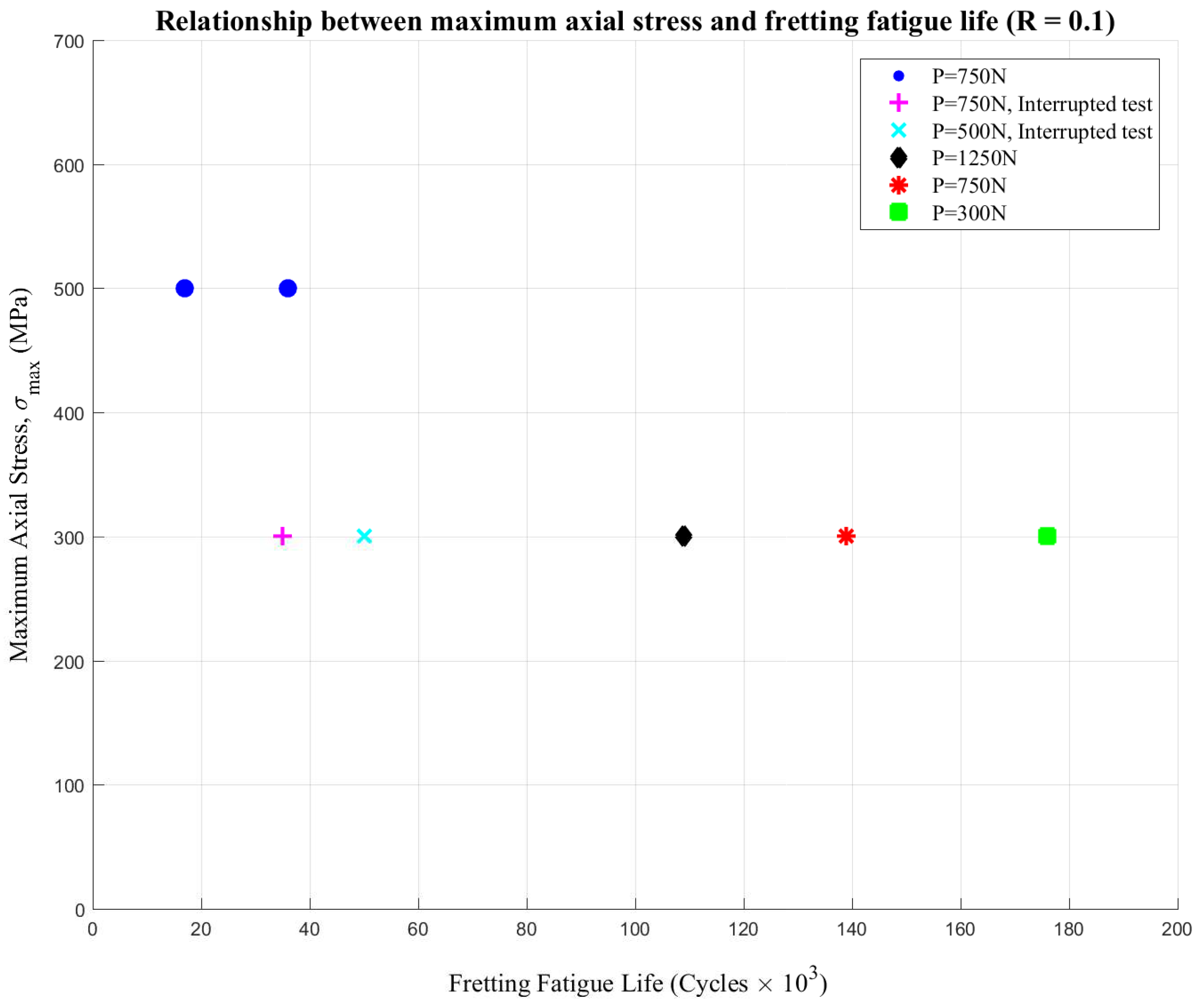
Figure 11 graphically illustrates the relationship between the maximum axial stress and fretting fatigue life
of the test specimens under different applied contact loads
P_
contact. As expected, at an axial stress of 300 MPa and a frequency of 30 Hz, increasing the contact load on the fretting pads leads to a reduction in fatigue life
. Furthermore, a comparison of experimental results for test cases 1, 3, 4, 6, and 7 shows that increasing the maximum oscillating axial stress significantly reduces fretting fatigue life. Interrupted tests were conducted on specimen
and specimen
to study the fretting damage and obtain a fretting map for the additive-manufactured Ti-6Al-4V alloy. The following section elaborates on the microscopic examination of test cases 1_7.
4.1. Microscopic Examination of the Fretted and Fracture Surfaces
After each fretting fatigue test, a microscopic examination was conducted on the fretted and fractured surfaces using a scanning electron microscope (SEM). The SEM images and corresponding analyses below provide insights into the characterization of fretting fatigue damage in metal additive-manufactured Ti-6Al-4V alloy specimens, contributing to the development of a fretting map.
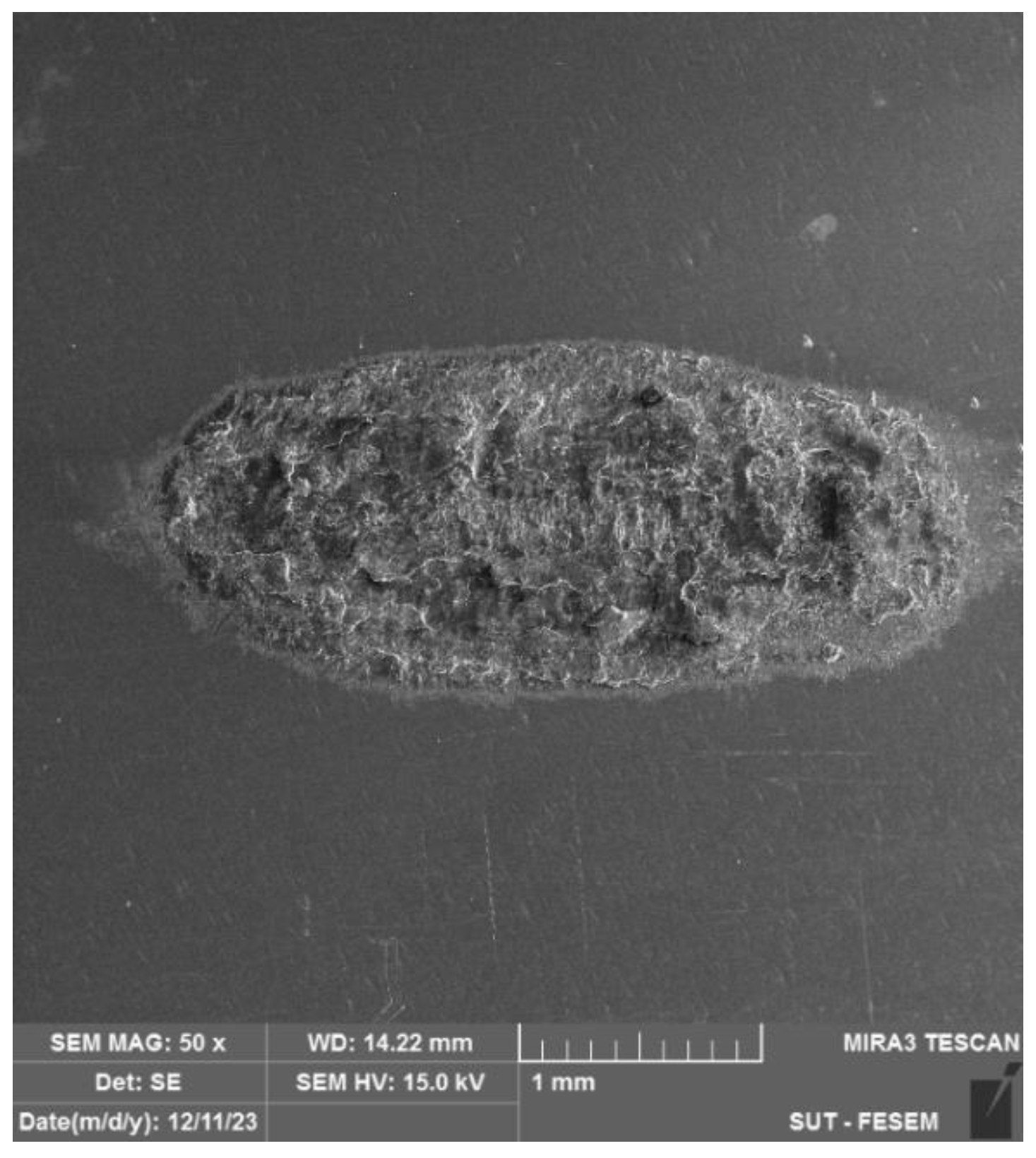
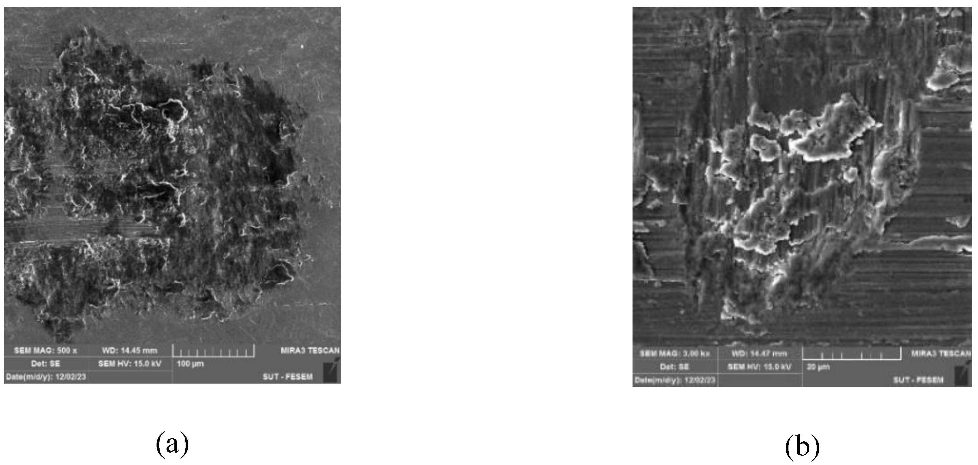
Figure 12 shows a low-magnification SEM image of the fretted surface of specimen
, where the test was interrupted to characterize fretting damage.
As observed in
Figure 12, the fretting damage characteristics near the contacting edges differ significantly from those observed closer to the center of the contact surfaces. At the contacting edges, the dominant damage modes are slip, stick, or a combination of both. In contrast, delamination-type damage is primarily observed near the central contact zone.
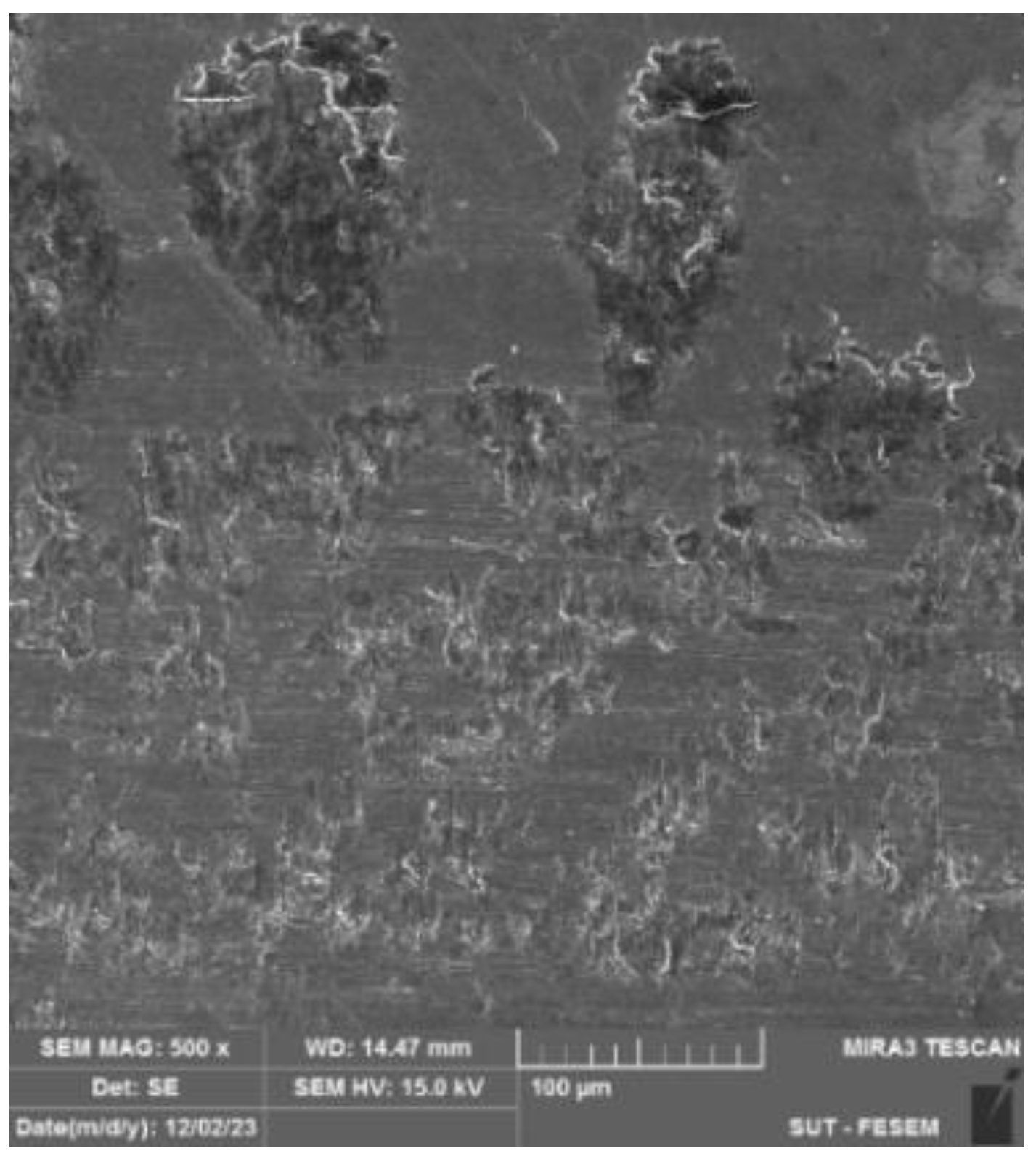
Figure 13 shows a higher magnification of the fretting damage on the contact surfaces of tested specimen
, which was taken from a specimen subjected to interrupted fretting fatigue. Closer observation of the fretted region revealed various types of fretting wear, including stick, slip, and delamination, but no cracks were observed in this area.
Further SEM images of the surfaces exhibiting signs of fretting damage for test case
are presented in
Figure 14.
Figure 14a shows the presence of secondary cracks in the fretted zone of the specimen.
Figure 14b–d illustrate spalling and delamination damage, which are characteristic features of fretting fatigue. The SEM image in
Figure 14e presents potential pitting or cavity formation caused by fretting between two surfaces, which is a particularly intriguing observation. Conspicuously, this SEM image reveals distinct damage characteristics compared to those typically observed in titanium-based alloys subjected to fretting. The SEM images of the fracture surface of specimen
are presented in
Figure 15.
Figure 15a,b illustrate fretting damage, specifically pits, on the fracture surface at different magnifications.
Figure 15c,d illustrate the fracture surface characteristics of specimen
.
Figure 16 shows images at higher magnifications of the damage on the fretted region of specimens
and
.
Figure 16a exhibits stick–slip-like damage resulting from the fretting fatigue test on specimen
.
Figure 16b presents a rare view of three types of damage, stick, slip, and delamination, on the fretted surface of specimen
.
From a design engineering perspective, the coexistence of stick, slip, and delamination modes on the same contact surface highlights the complexity of fretting-induced damage in AM components. The observed damage diversity underscores the need for tailored design strategies, such as surface treatments, localized geometry modifications, or stress-relief heat treatments to mitigate damage progression. These insights provide crucial input for developing more resilient interface designs in turbine blades, orthopedic implants, and similar fretting-sensitive structures fabricated by metal additive manufacturing.
4.2. Fretting Map Extraction Using SEM Examination
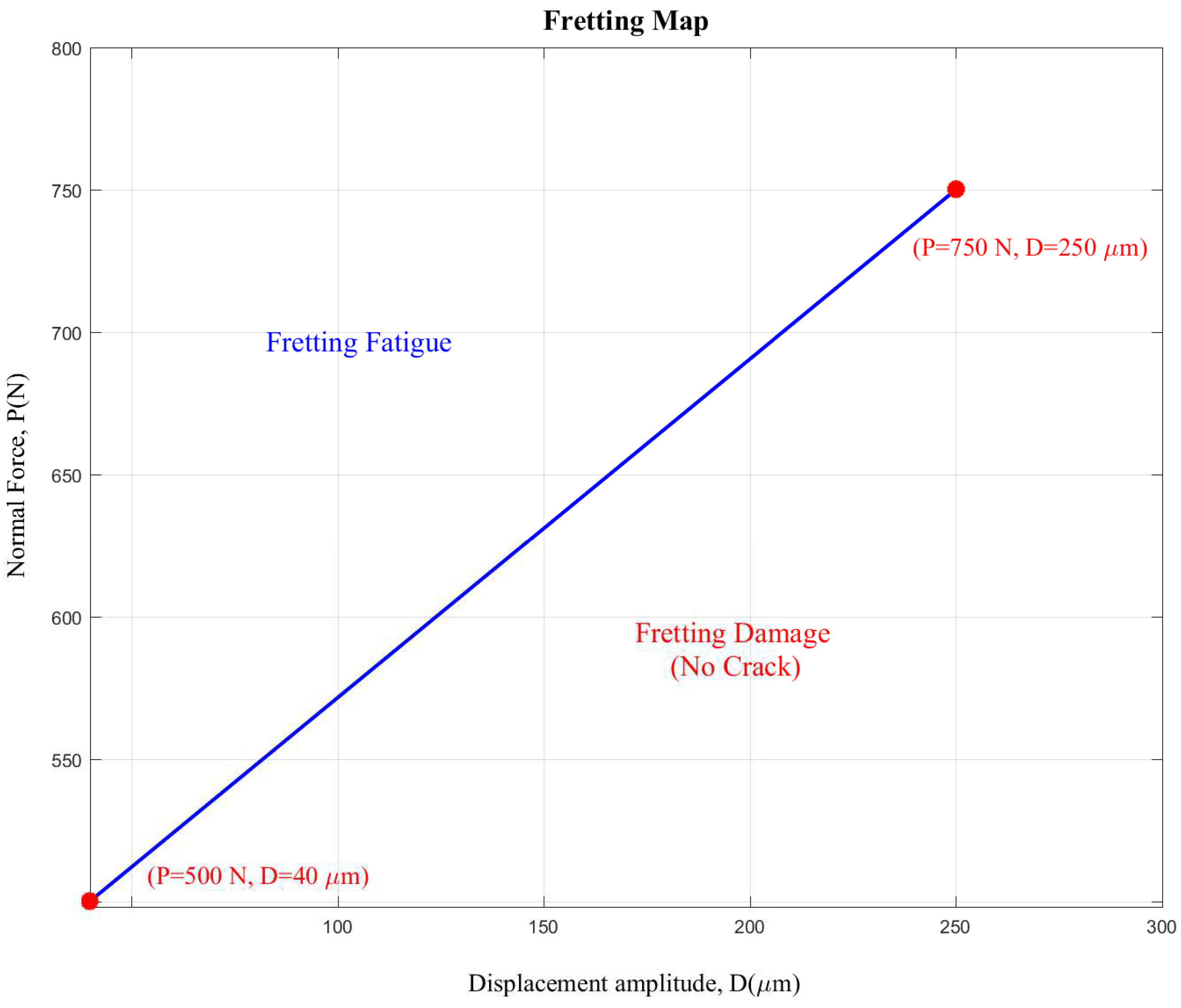
Based on SEM observations, a fretting map was developed for the additively manufactured Ti-6Al-4V alloy. In
Figure 17, the transition between fretting and fretting fatigue zones is shown using a linear fit, providing a preliminary boundary representation. The displacement amplitude on the x-axis refers to the measured relative slip amplitude between contact surfaces using SEM observations, which represents the cyclic relative motion during fretting.
Figure 17 clearly illustrates that below the linear curve-fitted line connecting the points, fretting damage has no significant effect on the fatigue life of metal additive-manufactured Ti-6Al-4V alloy specimens fabricated using the SLM method under a specific oscillating axial fatigue loading condition and frequency.
Regarding the design applicability, while the current map is based on a simplified specimen geometry, it provides a design aid that can inform safe operating zones and guide preliminary design screening for AM titanium components under fretting conditions. This fretting map offers a visual design aid by delineating safe operational regimes where fretting-induced fatigue cracking is minimized. It serves as a basis for determining allowable combinations of displacement amplitude and contact load in component design and may be incorporated into future computational design optimization workflows.
5. Conclusions
This study experimentally investigated the fretting fatigue behavior of additively manufactured Ti-6Al-4V alloy specimens, fabricated using the selective laser melting (SLM) method, in accordance with ASTM E466 specifications. Through systematic and standardized testing procedures combined with detailed microscopic examinations, key insights were obtained into the damage mechanisms and failure characteristics of AM Ti-6Al-4V under fretting fatigue conditions.
Scanning electron microscopy (SEM) analyses revealed secondary cracks within the fretting damage zone, along with characteristic spalling, delamination, and slip-and-stick damage patterns. Based on these observations, a fretting map was developed, providing valuable insights into the damage characteristics and crack initiation conditions under fretting and fretting fatigue situations. Importantly, the findings were translated into a design-relevant framework, where the extracted fretting damage map can serve as a tool for informing design verification and optimization processes. By identifying critical fretting damage modes that influence the fatigue performance of AM components, this work contributes to the development of fretting fatigue-aware design strategies for high-performance applications. Furthermore, this integration of experimental insights into a visual and data-driven fretting map offers a practical design-oriented tool that can support early-stage crack nucleation, material selection, and lifecycle reliability assessment of AM components subjected to fretting fatigue.
Future work should focus on expanding the number of test specimens and broadening the range of experimental conditions to develop a more comprehensive and robust fretting map. This will enable the integration of such data into computational design environments, ultimately supporting early-stage design evaluation, digital twin development, and lifecycle-based design decisions for metal additive-manufactured components.


