Based on the search review, in this Section, the following aspects are discussed, with specific reference to the most recent literature:
2.1. The Role of Parametric Modelling in Aesthetic Design Education
The range of CAD modelling software currently available on the market is diversified. By analysing the various CAD modelling systems, it is possible to identify significant differences in the operating logic and performance offered to the user. As widely recognised, the main distinction that can be made is between non-parametric and parametric CAD systems. The former does not consider the temporal succession of operations made by the user to arrive at the desired result (which is identified in the modelling history of the model). The latter, on the other hand, does keep track of this type of data. Traditionally, the term ”parametric modelling” refers to CAD logic that keeps track of the modelling functions used by the user and the relationships and constraints imposed. Conversely, “non-parametric” modelling only considers the last configuration of the digital model modified by the user and allows interaction with this, but not with the models resulting from previous operations.
Both strategies present advantages and disadvantages: on a general level, non-parametric modelling is usually more intuitive, requires less knowledge of the modelling environment within which one moves, and is easier to manage by the software, which does not have to keep track of many parameters and relationships, only of the final result. At the same time, however, the user has no access to the modelling history of the object and can only interact with its final instance. Modelling functions are usually less advanced [
10].
Parametric modelling, on the other hand, imposes a complex management of relationships between modelled geometric features: the software must keep track of the temporal succession of operations, geometric constraints, dependencies between features, and dimensional parameters set by the designer. All these elements are introduced by the user through the graphic interface and interpreted by the software through a system of mathematical equations, which becomes increasingly complex as the number of relations entered increases. This information management system allows the user to freely modify any function used during modelling. All operations performed by the user remain accessible within the so-called “feature tree”, an element of the graphic interface that collects them in chronological order.
Parametric modellers are also the CAD systems that come closest to the worlds of industry and manufacturing. Many of the modelling functions that can be selected within these systems directly invoke manufacturing processes (e.g., extrusion); consequently, the shapes generated by these functions maintain a link with manufacturing processes [
10]. As widely known, the basic modelling approach in parametric systems starts with the construction of a two-dimensional (2D) sketch on a model reference plane. The 3D modelling algorithms that analyse this graphic element’s geometry to create three-dimensional surfaces or solids utilise it as fundamental data. These forms remain linked to the basic sketch that created them and are affected dynamically by any changes to it. The shapes generated thus remain linked to their two-dimensional representation, reinforcing the link between modelling and drafting.
The possibility of modifying geometrical relationships and dimensions lends itself particularly well to industrial designs. If during the preliminary design phase, the designer’s objective is to attain a concept that conveys the idea and style of the product as quickly as possible, as the design activity proceeds, shapes and dimensions are defined through detailed design. At this stage, the ability to modify the structure of the generated model is a fundamental value, saving time and reducing design costs. Such changes will be effective and intuitive if the original modelling has been conducted effectively. If the modelling is well executed, the shape of the designed object should be determined by geometric constraints; thus, by changing a few dimensional parameters, different versions of the same topology can be obtained. An example is shown in
Figure 2, where a solid, defined by a single modelling history, is represented in four different configurations as the control parameters change.
The same mechanism of dependencies and relationships established within a part between modelling functions can be extended by introducing the same connections between several parts within an assembly. In this way, the benefits of parametric modelling can be extended to models consisting of several components. The user can thus create different configurations of an assembly in which the same components are arranged in different configurations and positions by imposing mating constraints between the parts. Similarly, the user has the possibility of modelling dependent couplings between parts: the diameter of a hole, for example, could be linked to the diameter of the pin to be housed there. The result is a design that lends itself to dynamic modification without the need to intervene at each iteration of the original modelling functions. As mentioned earlier, parametric modellers are also generally characterised by the presence, within the modelling environment, of a whole series of tools aimed at analysing the performance and manufacturability of the designed component. Most of these tools are oriented towards industrial design and create direct links between the worlds of design and production.
To these ends, in [
11], parametric design’s generative and evolutionary features are examined. The work suggests carrying out a thorough study to conceptualise designers’ problem-forwarding and solution-reflecting parametric design techniques. The solution-reflecting approach, which focuses on the designing solution space, can provide original solutions through parametric design. The efficient adoption of parametric design methods to better meet the demands of digital design and visualisation in many industrial sectors is supported by a deeper understanding of these techniques. In [
12], by employing forms as parameters and conceptualising parametric design as a generic process, a set of design methods are utilised to improve the design capabilities of a parametric model to execute design variations. As a result, a parametric model develops into a versatile tool that facilitates modifications at the topological and geometrical levels. Starting from the aforementioned literature, a number of specific tools can be taken into account to guide non-expert designers towards the creation of engineered products; these tools are, not by chance, offered to students by the most advanced CADs:
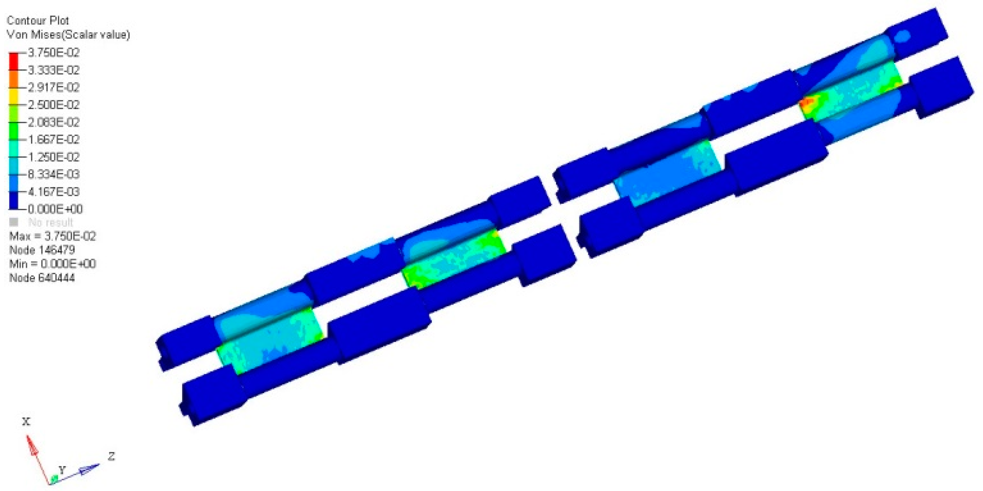
Finite element simulation tools—more modellers offer finite element calculation software directly within the drawing environment. In this way, both structural characteristics (static or dynamic) and performance under thermal loads can be evaluated. In the most extreme cases, tools for CFD analysis and non-linear dynamics simulations are also offered. An example in this regard is shown in
Figure 3 [
13].
Mould design—there are numerous plugins that can not only help the designer design the mould from a geometric point of view, but also simulate the filling, deformation, and cooling of the part. Analysing the moulding behaviour of the part before the mould is made allows the necessary measures to be taken if necessary to achieve better results.
Analysis of undercuts to assess the extractability of the component drawn from a mould or similar in relation to an extraction direction.
Drafting and production of graphic tables. Although the creation of a 3D drawing has become the new standard for product design, even today information for the manufacturability of a product is commonly placed on views and sections represented in two dimensions.
With reference to the last point, by using a drafting tool, it is possible to:
Specify dimensions, which establish the dimensional limits of all product features (overall dimensions, position of holes, dimensional interrelations between different portions of the product, etc.).
Specify dimensional tolerances, i.e., the limits of dimensional variability of each feature for which a dimensional check is required in the workshop, to guarantee the correct coupling between several components.
Specify geometric tolerances, which consider the inevitable shape errors that real surfaces have with respect to the ideal ones indicated on the drawing. Although the ISO 1101:2017 standard [
14] also provides the geometric specifications of products for drawings made in 3D, in practice almost all manufacturing companies still use 2D drafting for this type of information, as it is easier to apply (
Figure 4).
All the results of analyses and verifications can be automatically incorporated into the technical report of the project, thanks to integrated management tools offered by the most complex CAD systems; all these tools allow the designer to carry out a series of preliminary verifications with as little effort as possible, increasing the value of the project and allowing a progressive transition from concept to finished product condition.
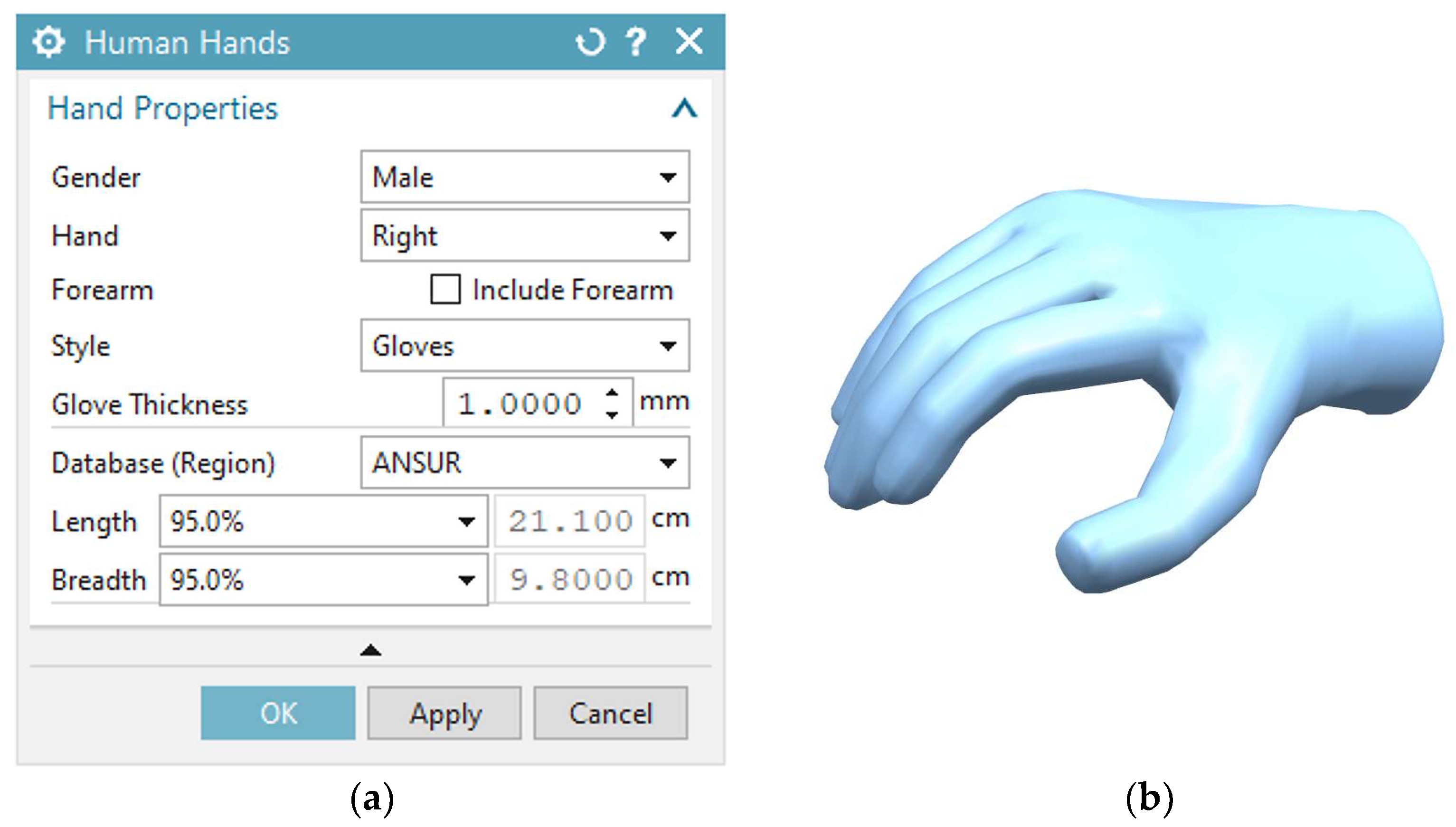
A further category of tools that seeks to offer design support, particularly useful for less experienced designers or those with limited technical expertise, is the set of tools for guided modelling of certain predefined components. An exemplary case in this regard is the modelling of connection elements such as screws, nuts, studs, and similar components. Since these are presented as standard elements in most cases, it is possible to refer to pre-modelled templates for the modelling phase. The user, in this case, is only required to enter the template code of interest, or the measurements they want to be respected, and the software autonomously introduces a solid with the required characteristics. The same principle can be extended to less common components or those with more complex geometry; in this case, the a priori definition of valid shapes that can be adapted to the designer’s needs may be more complex. A significant example could be the possibility offered by NX, a CAD system developed by Siemens (Siemens AG, Munich and Berlin, Germany), to insert anatomical shapes defined by reference measurements (e.g., hands, the basic structure of the human body,
Figure 5) into the modelling environment. The introduction of these models can be particularly useful for the designer to develop human–machine interfaces and take care of the ergonomics of the project.
By taking advantage of the possibility offered by parametric CAD to call up the modelling tools offered by the programme’s graphical user interface in a programming environment, it is also possible to develop modelling tools customised to the designer’s needs. This effort is justifiable in the case of components that always have the same characteristics and shapes but with different dimensions each time.
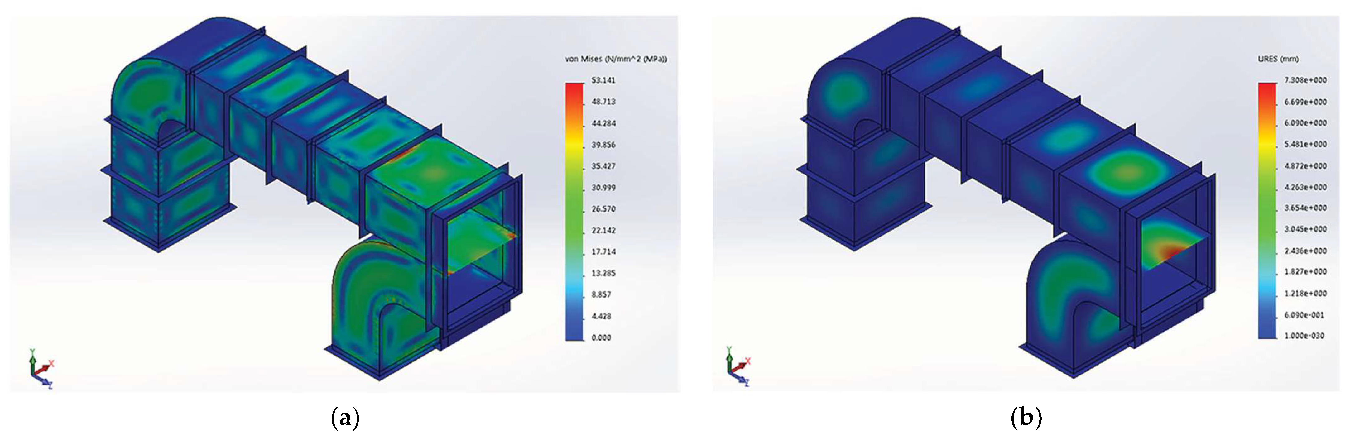
Remaining in the more traditional field of mechanics, an example of this phase is the tool called ‘DuctWorks’ [
15] which implements a CAD-based tool supporting and partly automating the complex structural ventilation system (VS) design process (see
Figure 6).
The tool is specifically designed to perform a structural assessment of dynamically inserted ducts within a centrifugal compressor conditioning system, which is of the utmost importance given the considerable dimensions and stresses to which this type of VS is subjected in the specific field of the power generation industry. Thanks to all the functions and features described, parametric modelling presents itself as a technology preferentially oriented towards the world of industrial design and production.
2.2. The Role of Generative Design and Topological Optimisation in Aesthetic Design Education
The latest developments in methods and tools for aiding aesthetic design are related to the development and introduction of artificial intelligence algorithms into the design world [
16]. SOLIDWORKS software maker Dassault Systemes Company (Vélizy-Villacoublay, France) is one of the top businesses that has used AI in its design product [
17]. The company established xDesign, a technology that operators can use to deploy various solutions to their design difficulties instantly through cloud collaboration and that leverages AI to extrude and draw in engineering design projects. The operator starts by developing the model and specifying the restrictions. The part will then be instantly generated by SOLIDWORKS xDesign using AI that is integrated into its system depending on the limitations specified by the user [
18]. Additionally, extended reality (i.e., virtual reality (VR), augmented reality (AR), and mixed reality (MR) in the context of this study) has been researched for AI in CAD. In such a setting, simulation outcomes occur in a 3D environment, enabling the viewing of things in three dimensions [
19]. Thanks to the development of computing systems, the search for ever more efficient algorithms, and the emergence of remote computing systems (e.g., the ones working in the cloud), it is now possible to apply optimisation algorithms of several types to the study of structural problems. These tools, initially offered in independent software packages, have progressively been integrated within traditional CAD environments to ensure simplicity and speed in the use of tools in a synergetic manner.
According to [
20,
21], the use of computational tools in design may have an impact on human designers’ actions, such as how they interact with each other and how confident they feel as they work through a design. Similar to how human designers behave, computational tools can function differently. Designers may modify the produced designs to make them more visually acceptable because, for example, some design characteristics, like aesthetics, cannot readily be measured for the Generative Design tool. This subjective choice, which varies from designer to designer, may lead to various design outputs for a given design purpose [
22].
Recently, a range of technological sectors have increasingly used generative approaches, i.e., Generative Design (GD), a specific kind of software and computer-aided design approach that leverages AI to speed up the design process. Using Generative Design tools, engineers may swiftly loop through several design options and select the best one based on a set of criteria [
23]. Some functions that are typically completed by human designers, such as concept creation and product optimisation, can be delegated to the Generative Design tool in Generative Design. The way designers approach the design process may be drastically altered as a result. Designers may think about how to establish a system for design that would enable the design tool to generate a large number of legitimate outputs rather than how to create multiple one-off designs. Setting the necessary requirements, production techniques, and product architecture at an early stage of the process can help with this.
The knowledge the designer brings to each stage of the design process is arguably the most significant input into the Generative Design process. As they define and iterate on the objectives, parameters, and restrictions, choose among the results produced by the tool, and refine to create the final design, designers apply their design expertise, intuition, and understanding of the users and context to the design process. According to one designer, the Generative Design tool may be developed upon this designer’s experience as a base.
However, GD should be used in the design’s starting phase, giving engineers and aesthetic designers valuable feedback for initial design possibilities. Therefore, GD can see a much wider and more innovative design space, even for inexperienced designers. In fact, GD can be adopted when the shape of a product is not defined and there is a need to consider several different options. taking into consideration the desired material and manufacturing method. In particular, it can elaborate and provide a human user with several reasonable answers for a design challenge by utilising artificial intelligence capabilities. It is possible to use methods and tools that strive to maximise a target function given to the algorithm and fulfil a set of enforced design restrictions. The suggested alternatives are the outcome of an artificial intelligence-guided iterative search of the relevant solution space. These tools have recently seen a rise in popularity in the design community because of the considerable increase in computational power available. In the realm of architecture, GD has made some initial inroads [
24] and has often been used in open-problem settings with huge design spaces. Practically speaking, GD tools just look for a mathematically defined solution to a problem; this frequently leads to an iterative optimisation process that aims to minimise an objective function. In light of this, GD has demonstrated its use in identifying unusual solutions that do not correspond to the usual set of forms or configurations employed.
This technology has recently been extended using the GD feature of Autodesk’s CAD Fusion 360
® 2023 program. Later, Autodesk used this name as the commercial designation for an advanced proprietary version of a Topological Optimisation tool. Currently, the program only allows users to attack components that are subject to static caries.
Figure 7 [
24] shows the Generative Design framework.
The Autodesk program uses the same workflow, but instead of offering the user a single solution, it suggests several viable alternatives that the project manager should consider. The program displays the alternatives together with the findings of the carried-out structural analysis. The developer can choose the most convenient method by fusing the data generated by the program with their own personal knowledge. The most practical solution could not be the one with the best mechanical characteristics for a variety of reasons, which the user is free to consider. Ergonomics, aesthetics, and producibility are some of the key design factors; however, they cannot easily be codified and understood by artificial intelligence. The project manager must evaluate how to include these aspects considering the model’s structural performance using such a strategy.
This makes it possible to utilise the benefits of both approaches. Due to the opportunity it provides to explore unique and unusual forms, this technology has found widespread use in the field of design.
Figure 8 shows an example [
24].
Since the Generative Design process is constraint-driven, it requires a new way of thinking from traditional design, which results in a distinct kind of creativity in the process. In order to have an impact on the ultimate design product, designers must be creative in how they express the objectives, parameters, and limitations. According to [
22], Generative Design tools may be creatively used by designers as a component of the design process. Although Generative Design tools might be thought of as a way to produce a finished product, the Generative Design process can also be used to discover the design space, produce early concepts as inspiration, and investigate the range of design options.
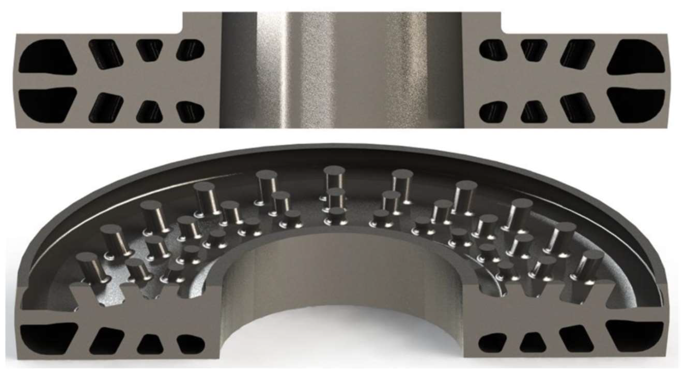
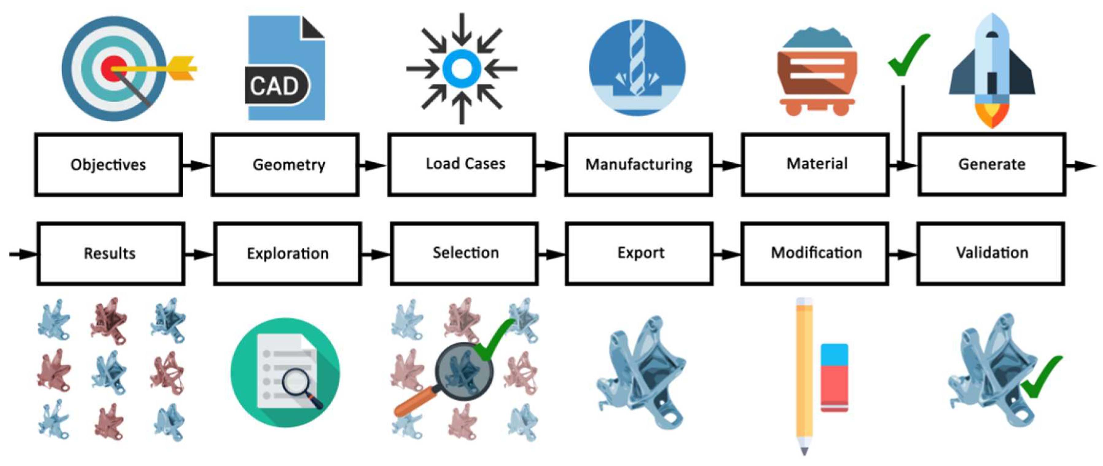
At advanced design stages, when the initial geometry has already been established, the aesthetic designer can leverage the concept of Topological Optimisation (TO).
To help the resultant layout achieve a predetermined set of performance goals, topology optimisation approaches enhance material distribution within a given design space (for a particular set of boundary conditions and loads). When a form divides into two or develops holes, for example, topology optimisation enables changing the topology of the structures [
24].
In TO, the physical and manufacturing constraints within the initial design of a mechanical part must be optimised in terms of a topology optimisation objective like minimum strain energy, also known as “compliance,” after the geometrical region subject to optimisation has been assigned. In contrast to the classical design approach, in which the designer assumes a shape that is subsequently verified through calculations of diverse types, in this case, it is the calculation itself that defines the shape of the designed component, once a preliminary geometry is defined.
The user must provide the optimisation algorithm, via a graphic interface, with all the information required to define the problem, and in particular:
Working volume within which the component can develop and take shape.
Any volumes that must not be occupied by the material.
Properties of the material to be used.
Loads and constraint conditions, correctly stated in position and intensity.
Objective of the analysis—which, depending on the case under consideration, may be the search for the best compromise between stiffness or lightness, the realisation of a component with a constraint on the mass, or more complex objectives (maximising heat exchange efficiency, or the dynamic behaviour of a structure).
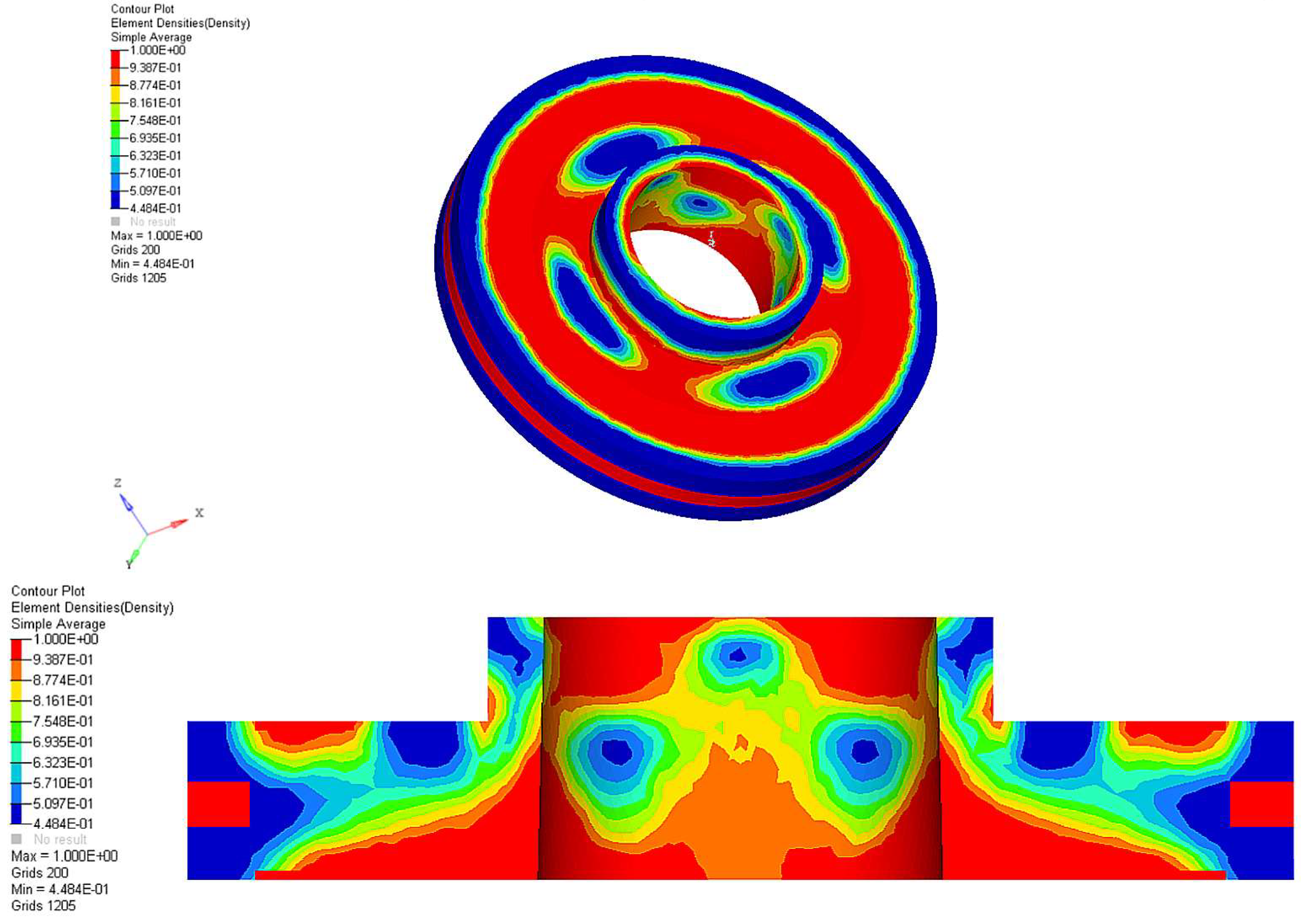
The software processes the information received to identify the most effective form (i.e., material distribution, see
Figure 9) (thanks to a series of FEM analyses) and proposes an initial solution to the user, who can modify and improve the result.
The design is thus guided by the search for a solution that maximises expected performance, rather than by the designer’s experience, which might lead them to propose known shapes (for an example, see
Figure 10 [
25]).
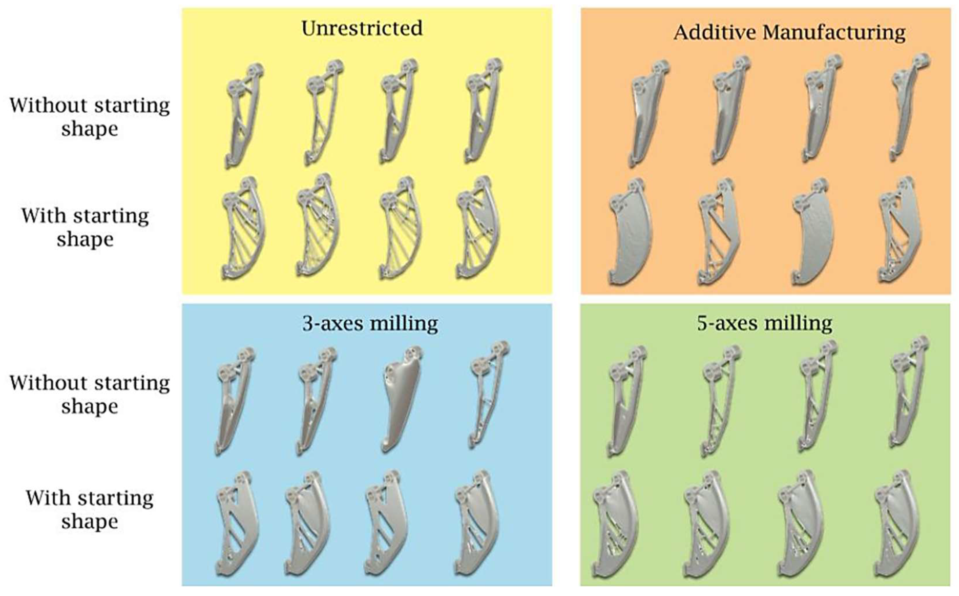
2.3. The Role of Additive Manufacturing in Aesthetic Design Education
The role of additive technologies (ATs) in the prototyping issue of design is extensively discussed in [
26], which explores the literature contributions focused on the different perspectives of prototyping activities for design purposes, searching for both available knowledge and research needs concerning the correct exploitation of ATs. One of the main findings of such a work is that regarding the influence of AT-based prototyping on design results: the CAD modelling of the solution to be physically prototyped is the factor that has the most influence on designers’ cognitive processes. A further intriguing research idea arises as a direct result of the potential cognitive constraints brought on by the required CAD: looking into the feasibility of developing a CAD software and/or hardware ad hoc for Rapid Prototyping in the context of designing, capable of somehow promoting positive cognitive activities of designers, and subsequently allowing to fruitfully exploit manufacturing to enhance creativity of design outcomes. The primary application of this issue, therefore, is the prospective availability of CAD platforms (or plugins) for Rapid Prototyping to better encourage creativity in the initial design stages.
Moving from the product’s conceptual design—where, as previously mentioned, context, target, innovation (both in terms of form and functionality), alternative materials, and style are prioritised—to the actual project for production ushers in a challenging stage in which the project manager is required to work on a continuous revision of the various developed concepts in order to support the operational phase of the product. The ability of the product designer to modify their own product concept to the specifications of its manufacturing is crucial [
27]. As a result, it is important to understand the possibilities and limitations of the technical approach being used. In this executive phase, it should come as no surprise that the designer frequently collaborates with mechanical engineers and technologists who can assess, set up, and validate all conventional mechanical processes, including foundry forming processes, deformation processes (rolling, forging, extrusion, and sheet metal machining), subtractive chip removal processes (milling, turning, and grinding), and joining processes (welding, brazing, and bonding).
The use of these technologies almost always imposes restrictions on the topology and geometry of the products to be made, even though they are not necessarily conventional [
28]. These restrictions are represented in the product design through a number of decisions and compromises that inevitably cause the concept and the result to diverge dramatically. The usage of additive technologies, often known as 3D printing or fast prototyping methods, has undergone a dizzying expansion and subsequent proliferation in both commercial and academic settings over the past three decades to provide the designer with more freedom. In contrast to traditional machine tools (lathes, mills, and drills), which remove parts of existing material to produce finished goods (subtractive manufacturing), 3D printing builds objects by adding material, allowing the creation of finished products or parts of them. The operating theory relies on the idea that everything is made up of several parts, each of microscopic thickness. Thus, the challenge is reduced from three dimensions to two dimensions and the quick prototype is built section by section.
However, over time, its use has come to be increasingly considered as a substitute for the actual final production of things (or sections thereof) that are challenging to make using conventional subtractive processes. Additive Manufacturing was initially employed for the fabrication of prototypes. The number of contributions per year that list “Additive Manufacturing” (or “additive manufacturing”) among their keywords—10 in 2006 versus more than 1100 in 2020 (database: Scopus, 2022)—evidences the recent significant rise in interest in research on topics related to 3D printing. These contributions include a wide range of research topics, such as materials, software, device technical progress, and effects on design methodologies.
In comparison to the prototyping stage alone, additive technologies are poised to play a significant and useful role in contemporary product design and development by offering the designer priced (and quick) support so they can create physical prototypes that replicate some aspects, including functional aspects, of the final product. This is made possible in part by the spread of low-cost technologies. Scholars, therefore, have recently produced interesting studies concerning taxonomies, strategies, and educational applications related to the use of prototypes in conceptual design. According to recent literature [
27] there are as many as four roles that can be attributed to the use of prototypes within the product development process. Prototypes can be used as a starting point to comprehend how a product functions or to confirm that client criteria are satisfied. In this regard, using a real prototype is more practical than using a computer-aided design (CAD) model. Second, communicating with the various stakeholders engaged in product development may also be carried out via prototypes. The third purpose of prototypes is integration, which is defined as the capability to confirm that the parts and subsystems that make up a specific product operate as planned. Prototypes also serve the vital duty of serving as an indicator of the designer’s progress during the development process.
The so-called zero principle [
29], which states that using 3D printing is typically discouraged for any object that can be produced satisfactorily and affordably by using traditional mechanical manufacturing technologies, must be kept in mind when it comes to the direct production of products that are ready for market. When the zero principle fails, the designer can turn their gaze toward Additive Manufacturing. Thus, there is a paradigm shift: the designer must shift their attention from a design constrained by the traditional manufacturing process and turn their gaze toward what is known as Design for Additive Manufacturing (DFAM) [
30]. As widely recognised, DFAM is a set of design methods in which functional performance and/or other key product life cycle considerations, such as manufacturability, reliability, and cost, can be optimised based on the capabilities of Additive Manufacturing technologies. This means that using the 3D printing process alone as a design tool is insufficient. To determine if AM is a practical choice, the designer must also consider the complete chain of finishing procedures necessary to make the finished product. To significantly limit the volume of media that must be created, saving both time and resources, they must also pay close attention to the design of the shape of the object to be produced and the favourable arrangement within the machine. Designing in accordance with the canons of DFAM and making prototypes with Additive Manufacturing offers countless advantages, especially when one wants to produce products of unconventional shapes, such as in the case of designing topologically optimised objects or those resulting from Generative Design. Moreover, with the canons of DFAM, it is possible to design objects in which a specific function, even a complex one, can be fulfilled by minimising the number of components.
Direct production of mechanisms (ready-to-use—without the need for assembly) can in fact be realised in two ways:
Multi-part mechanisms—in many AM processes, it is possible to make mechanisms with parts that move to each other without the need for assembly. Kinematic connections (hinges, guides, etc.) can be made directly before removing the supporting material.
Compliant-type mechanisms—the type of movement between the input and output of the mechanism is achieved by bending some elements; the mechanism is made in one piece.
For what concerns the use of Additive Manufacturing as a supporting tool for Generative Design, it should be considered that the manufacturability of a novel shape is not straightforward. Generative Design, as previously described, enables the insertion of manufacturing restrictions that are considered in the analyses. A CAD program does not give any extra information on the impacts imposed by activating such limitations, even though their overall influence may be seen when comparing the class of forms created in each category of design solutions. As a result, CAM software programs (like those in Fusion 360) should be used to compute potential machining pathways to verify the manufacturability of very complicated designs. This makes it possible to determine whether the addition of production limitations enables the discovery of geometries that are optimum even while taking manufacturing feasibility into account.
Contrarily, most additive technologies are not compatible with high production numbers, thus it is crucial to strike a balance between aesthetic demands and the manufacturing process to make an educated decision on the latter. The materials used for the product play a crucial part in the mass manufacturing of design items employing 3D printing technology. Polymers, metals, biological materials, and ceramics are just a handful of the materials that are available compared to conventional procedures, and their pure mechanical performance (e.g., under taxing loads) is often lower than that made possible by subtractive processes. Additionally, printed items may experience residual strains, thermal shrinkage, and deformation. These factors must be carefully considered by the designer, for example by carefully examining how the part is positioned inside the print volume and refining the structure.
Furthermore, the designer should consider the costs involved in AM of designed parts. Costs associated with materials, equipment, manufacturing, and labour can all be classified as AM costs. The total unit cost is determined by adding these expenses together. Reused or wasted material, support design and layout, construction time, the maximum number of pieces that can be produced at once, level of complexity, post-processing time, and quality control are significant considerations to include when considering costs associated with AM. Furthermore, the analysis of AM costs is generally driven by two groups. The first category compares machining and injection moulding (IM), two standard methods, to Additive Manufacturing (AM). Identification of events and situations where AM is economically advantageous is the goal. Determining the resources that are used at various stages of AM falls under the second category. Information on the resources being used and their general use is controlled by this category [
31]. To this aim, several cost models have been studied in the literature. Among them, it is worth mentioning the work of Hopkins and Dickens [
32], who created a model to contrast classic processing techniques like IM with AM procedures likeSelective Laser Sintering ( SLS), Fused Deposition Modelling (FDM), and Stereolithography (SLA). The model was applied to different batch sizes and part designs to calculate break-even thresholds and individual unit prices. The breakdown of expenses was broken down into the three categories of material costs, labour costs, and machine costs. In this study, the model calculated SLS material costs without accounting for powder recycling.
Even ignoring the costs of production machinery, which can be considerably high for metal 3D printing, materials for use in Additive Manufacturing methods can cost much more than metal ingots or polymers for injection moulding. The exact costs depend on a variety of elements, including the Additive Manufacturing technique and the precise materials employed in manufacturing. It should be considered, however, that even if the cost of raw materials per weight is higher, Additive Manufacturing results in items that are simpler, need less time to make, and use up to 90% fewer raw resources overall. This balances out the high cost of raw materials, which, on average, only represent roughly 20% of overall manufacturing expenses. With the introduction of new material possibilities, these costs should decline [
33].
Once the aesthetic designer is aware of the above limitations, to which one must also add the incidence of time and cost of making the prototype/product, it is undeniable that 3D printing poses young aesthetic designers with numerous competitive advantages: manufacturability of complex geometries, reduction of intermediate processing steps (no blanks or semi-finished products), rationalisation of warehouse and process chain management, and reduction of production preparation time are some excellent examples. Finally, it is worth noting how material properties/characteristics can be customised and modified locally in the part (e.g., by employing digital materials) through the control of 3D printing process parameters, and how, as a rule, part complexity is not related to production cost.
The working principle of all Additive Manufacturing systems follows the following steps:
A 3D digital model (CAD model) of the object to be produced must be available. By now, all of today’s CADs (SolidWorks 2024, Catia v5, Siemens NX v. 2306, Fusion 360 2023, Rhinoceros 3D v.7, 3ds Max 2024, etc.) allow for such models, which may also be derived from three-dimensional scans of objects that have already been designed and, subsequently, modified. These models can also be the output of Topological Optimisation or steps related to Generative Design.
The digital model is translated into another type of file suitable for further processing by 3D printing machine software. The standard format for this type of file is STL (STereo Lithography interface or Standard Triangulation Language). The STL format consists of a set of triangular facets that approximate the original geometry [
34].
The STL file is read by the printing press software where it is also possible to set all process parameters including part orientation, work volume and media generation.
The machine software “slices” the resulting digital model (both the main 3D object and supports) into slices with a constant thickness (10 ÷ 500 µm depending on the building technology).
The geometric data for each slice is used by the machine to produce the object layer by layer by adding new material for each slice.
After production, the substrates should be removed, the parts cleaned and subjected to post-processing treatment such as painting, plating, heat treatment, etc.
It should be kept in mind how all 3D printing processes introduce a discretisation of the original shapes (geometries, features and CAD surfaces) that are used as input for the production cycle. As in any mechanical process, therefore, the final shape of the object will be different from the theoretical (“digital”) one. All AM processes introduce two “discretisation” errors: Faceting, due to the creation of a digital STL model for printing, and Staircase, due to layer-by-layer deposition. In addition, several defects are typically attributable to Additive Manufacturing and mainly due to the separate ways in which the part is oriented within the print volume. Thin walls, for example, may be thicker than desired, especially if they are not oriented vertically. A similar effect can be seen in the formation of holes. Conversely, thin walls with remarkably high inclinations may be weaker than they should be because of low material overlap between successive layers. Finally, the surface finish depends on the orientation of the workpiece within the working volume.
The choice of technology employed to create the prototype or product has a significant impact on the aforementioned. There are many technical options at the state of the art, but the following are now well known: Selective Laser Sintering (SLS), PolyJet printing, Fused Deposition Modeling (FDM), and Stereolithography (SLA) [
35]. A discussion on these technologies falls outside the scope of this paper, but useful hints can be found in [
36,
37,
38].


