Abstract
We present the design of a universal gripper based on the principle of liquid jamming. The phase change behavior of a mineral oil subjected to cooling is used for adaptive gripping and release of objects. The mineral oil is enclosed in a soft, compliant membrane molded into a spherical shape. The membrane with the liquid easily adapts to the shape of the object to be picked up. A thermoelectric cooling system is designed with a conductive spreader immersed in the oil to quickly cool the liquid held in a membrane. Once the membrane gripper conforms to the shape of the object partially enclosing it, the liquid is cooled below the phase change temperature, thus freezing the liquid and hardening the gripper around the object and effectively gripping it. We describe the design methodology of the gripper, part selection, and mechanical design. A proprietary controller developed by Venture Corporation is used for controlling the TEC module and the controller is based on a simple PID optimized using Ziegler–Nichols tuning for the P, I, and D values. The hardware is evaluated and the basic gripping functions on different odd-shaped objects are demonstrated. An invention disclosure has been submitted to the NUS IP office (ILO).
1. Introduction
Multi-fingered grippers and vacuum grippers are being widely used in industrial factories, and the recent push toward Industry 4.0 transformation and developments in robotic control has helped to accelerate the development of new gripper designs and robots. Conventional industrial robots relied on different end-effectors and grippers, suited for different types of jobs and objects and required exchanging end-effectors in between the process. The end-effector change was a bottleneck in the robot’s high-speed workflow as it requires downtime and multiple re-programming. A shift toward the use of universal robot grippers has helped to overcome these bottlenecks, and the universal jamming gripper has been an attractive solution not only for research/academic institutions, but also for commercial developers. The Universal Jamming Gripper (UJG), which consists of a single mass of granular material encased in an elastic membrane and a vacuum pump that extracts air, can passively conform to a wide variety of arbitrarily-shaped objects, and then be vacuum-hardened to grip the objects rigidly. These grippers can be classified under “gripping by the stiffness change”. The UJG is of special interest in this study and some of the important commercial and academic work on this topic are discussed below.
J. Amend et al. described the historical background and origin of UJG and the experiences and lessons learned from trying to commercialize the concept [1]. The term “universal robotic gripper” refers to a design of a robotic gripper that can grip a wide variety of objects of different shapes and sizes. The simplest of them can use a vacuum suction pad to pick. Complex multi-fingered designs with many degrees of freedom are also used for adapting to a wider range of applications. The jamming gripper uses a pocket filled with granular material that hardens when air is removed from the pocket, creating a low pressure or vacuum. Simpson was one of the first to suggest adding pockets of granular material to the gripping faces of steel tongs to increase the conformability of the tool surfaces [2]. Schmidt and Perovskii proposed designs for 1-degree-of-freedom jawed robot grippers based on the principle of vacuum hardening of pockets filled with granular material for a gripper [3,4]. Reinmuller and Weissmantel speculated that a single membrane filled with granular material might be able to grip an object and function as a passive universal gripper [5]. It was the publication of a seminal paper in 2010 by Brown, J. Amend et al. in collaboration with the University of Chicago, Cornell University, and iRobot, that this concept was practically demonstrated and came to be known as the jamming gripper [6].
The approach by Brown, J. Amend and team was completely different from the designs of the universal gripper available at that time (2010). A single mass of granular material replaces the gripper fingers. The mass of granular material flows around the object when the gripper presses against the object and conforms to the object shape. When a vacuum is applied to the granular material enclosed in a soft membrane, the granular material contracts and hardens quickly to pinch and hold the object without requiring sensory feedback. A volume change of less than 0.5% was sufficient to give a grasp force of many times the weight of the object being gripped and ensures a reliable grip. The jamming gripper works by the property of granular materials that transition between an unjammed, deformable state and a jammed state with solid-like rigidity. There are three separate mechanisms that come into action during the functioning of the jamming gripper that contribute to the grasping force and interlocking: friction, suction, and interlocking. This paper and invention inspired many new follow-up studies for the design of simple, yet highly adaptive systems that can perform well at fast gripping of complex objects.
John Amend et al. extended the concept of the jamming gripper described in the original paper by Brown et al. by incorporating two jamming grippers as part of a two-finger design [7]. The fingers incorporate pockets of granular material in the fingertips, which could achieve the six fundamental dexterous manipulations as well as precision and power grasps, using only two actuators for closing and opening of the fingers. The results suggest that particle jamming gripper design is a viable technique for reducing the complexity for a parallel gripper with better performance and dexterity.
J Kapadia et al. proposed two other modifications to the jamming gripper design by adding small nubs and fluidizing the granular media, which resulted in a significant increase in holding forces (by about 60%) and increased the range of object geometries [8]. Experiments show that the nubs extended the capability to grasp smaller objects where the gripper could use the interlocking forces in the granular media in the nubs.
One major issue with the original jamming gripper design proposed by Brown et al. was the difficulty for the jamming gripper to go back to its the original neutral state upon gripper release by stopping the vacuum pump and letting the chamber reach back to atmospheric pressure. Amend et al. proposed a method of using positive pressure to overcome this issue and to reset the gripper after every actuation [9]. Their approach was to use both positive and negative pressure to modulate the jamming transition in a universal jamming gripper. The jamming gripper design can passively conform to the shape of the target object, then be vacuum-hardened to grip it rigidly, and later use a positive pressure to reverse this transition and release the object, returning it to its original deformable state.
Many improvements on the original concept have been attempted to overcome the limitations of the jamming gripper and extend its performance range and applications. The design and prototype of a three-layer jamming gripper were proposed by Fujita et al. By controlling the inner membrane chamber pressure and jamming layer pressure, better control, gripping, and holding force and more consistent resetting of the gripper after each pick and release action could be obtained [10].
Y. Wang et al. proposed an inflatable, partially filled jamming gripper based on a novel grasping strategy of integrating positive pressure and partial filling, in which the positive pressure increases the contact area between the gripper and objects, and the grain package in a partial-filled state provides significant grasping adaptation [11]. Better compliance and robust grasps could be achieved for off-axis objects compared to a fully filled jamming gripper.
Jamming grippers use bulky vacuum pumps to create negative pressure required for the jamming. Replacing the vacuum pump with an electro conjugate fluid (ECF), a type of functional fluid was proposed by Y. Tanaka et al. ECF generate a strong jet flow by applying a high DC voltage between the positive and negative electrodes. The jamming gripper was demonstrated using jet flow generated by the ECF and the jamming of granular material [12].
Jamming grippers traditionally use hard particles such as steel beads, glass beads, rice, salt, or sugar. H. Götz et al. proposed holding force enhancement using soft particles. Applying a vacuum on a gripper filled with expanded polystyrene beads (EPS) leads to a squeezing effect between the gripper and the object, due to its volume reduction [13]. This effect significantly increases the static friction between the object and the membrane.
David Howard et al. investigated the optimization of the membrane design for granular jamming grippers by using multi-material 3D printing and an evolutionary algorithm to search through a design space to find the optimum [14].
Soft robotics has become important in recent years where delicate, yet effective interaction is required. Shadab Zaidi et al. provided an overview of developments in soft grippers based on different actuation technologies. Pneumatic, cable-driven, shape memory, electro-adhesion, and electro-active polymer-based actuation methods are surveyed. Among the multiple designs reviewed, a pneumatically actuated manipulator with a functional tip, targeted for surgical applications is mentioned. When granular jamming was introduced to a normal pneumatic manipulator, using 0.1 MPa vacuum pressure, the stiffness of the manipulator increased up to 80% [15].
A variable stiffness soft robotic gripper proposed by Y. Shan et al. has an inner layer filled with the granular jamming material while the outer layer is a soft actuator [16]. A torsional motion applied to an inner fiber bag results in variable stiffness jamming of the inner layer around the object.
H. Wei et al. proposed improvements for a soft gripper by adding a variable stiffness module that uses a folded plate mechanism (FPM) [17]. This FPM allows rigid multi-directional loading and combines it with particle jamming to obtain localized variable stiffness similar to the characteristics of a finger grasping structure.
Layer jamming has been studied on pneumatic actuators to create a hybrid version. Layered material has a significant effect on the performance of the jamming actuator. C. L. Tennakoon et al. used P220 grit sandpaper as the layered material for the hybrid actuator [18]. The actuator shows around a 25% reduction in bending angle compared to the typical PneuNet actuators. The integrated jamming element can also act as a locking mechanism for the hybrid actuator.
Though many variations of particle jamming grippers have been investigated, the drawback of such grippers, such as the difficulty in resetting the gripper to its natural state after releasing the object, the requirement for a pneumatic system for positive and negative pressure supply, aerosol contamination due to the granular particle being used etc., could be mitigated only to a limited extent. It was observed that “a liquid interstitial fluid (a hydraulic jamming gripper) is a promising area of future research that may generate significant increases in holding force” [1].
Attempts have been made to use liquid as a medium for jamming grippers. In 2015, German Festo Company came up with a biomimetic gripper using an elastic membrane shaped like a cup, liquid, closed pneumatic components, piston, pump, and a driving mechanism to manufacture a self-adaptive gripper imitating a lizard’s tongue [19]. The piston motion pulls the cap tip inwards, allowing objects to be gripped during the inverting motion.
In our work presented in this paper, we propose a new concept, which, to the best of the knowledge of the authors, has not been explored before. The concept proposes to use fluid as the medium in the membrane and achieve the jamming effect by freezing the fluid quickly around the object. The concept proposed has several advantages over the conventional granular jamming gripper. Better compliance to the object’s shape is possible by using liquid as the medium for jamming. Pneumatic system is not required because the phase transition property of the liquid is being used. Gripping force control and the ability to handle delicate objects can be achieved using rheological properties of the liquid during the phase transition. The gripper consists of a membrane semi-filled with suitable fluid. The gripper approaches and presses against the object to be picked. The soft membrane and the fluid inside conform to the object shape. The liquid is cooled rapidly and, as it transitions from liquid-to-solid state, the gripper freezes around the object, thus enabling a positive grip. To release the object, the fluid is heated and the reverse phase transformation from solid to liquid happens. The membrane becomes compliant, and the object is released. Thermoelectric cooler (TEC) can be used for rapid heating and cooling of the fluid to alternate between solid and liquid states. A conceptual design is shown in Figure 1.
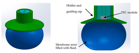
Figure 1.
Liquid jamming gripper: concept design.
A prototype was made and gripping experiments on 3D printed and odd-shaped objects were conducted. The gripper performance varied depending on the shape and surface texture of the object. Further improvements in design and construction were identified for improving the gripper capabilities.
The paper is organized as follows. Section 2 discusses the proof of concept and the conceptual design of the liquid jamming gripper. The choice of materials and the detailed design of the various components of the design are discussed with justification.
Section 3 describes the design construction using the selected components, pictures of the actual prototype, the test set up, and performance evaluation.
Section 4 discusses the test results, the findings from the study, the issues found, and the improvements needed. Adapting a Lifting design to other gripper configurations such as a two-finger gripper design is also discussed.
Section 5 concludes with recommendations for further work required to improve and extend the capabilities of the liquid jamming gripper and possibilities to explore commercialization.
2. Design Realization
Proof of concept was demonstrated using a party balloon partially filled with coconut oil, cooled using icepacks around it. The gripper could comply with different objects and effectively grip and lift many odd-shaped objects. Figure 2 shows the demonstration of concept.

Figure 2.
Demonstration of concept showing the picking up of different objects using a party balloon semi-filled with coconut oil frozen around the object to be picked up.
A more detailed preliminary design is shown in Figure 3. For efficient and fast cooling, the Peltier must be able to absorb the heat from the liquid without obstructing the deformation of the membrane around the object. A spreader in contact with Peltier is designed to dip in the liquid, which helps to maintain the gripper form and shape during liquid phase. The membrane is constrained between the Peltier holder and the membrane holder to ensure leak proof holding of the gripper.

Figure 3.
(a) Concept design of liquid jamming gripper and (b) cross section with details.
2.1. Choice of Materials
The main components of the liquid jammer design are shown in Figure 3. A thermoelectric cooler is used for the rapid cooling of the liquid. It is a semiconductor material that works by the Peltier effect. The device has a hot and cold side and when a DC electric current flows through the device, it pumps heat from one side to the other. The heat taken out from the cold side is dissipated using a heat sink attached to the hot side. The cool side can thus go well below room temperature. Commercial high power TEC modules consist of a rectangular array of Peltier elements stacked together and connected electrically in series and thermally in parallel. Figure 4 shows typical construction of a TEC module.
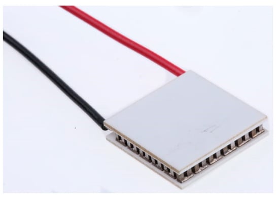
Figure 4.
TEC module.
Aluminum is selected as material for the spreader. Aluminum has low specific heat (0.9 J/g-°C). The lower the specific heat capacity, the lower the power required to raise or lower the temperature of the material. This helps to reduce the power rating for the Peltier module required to cool the spreader to below the freezing temperature of liquid. Aluminum alloy 6061 selected for the thermal spreader has high thermal conductivity of 152 W/m °k. This helps the tip of the spreader reach the low temperature faster.
The membrane should be flexible enough to comply to the shape of the object easily. A thin membrane ensures low stiffness but has lower tensile strength and is easy to tear. Synthetic or natural rubber latex is a suitable medium to mold the membrane in a fast and easy way. For this study, natural rubber latex commonly used for makeup, masks, and hobby projects was used.
The membrane holder and all design features to hold the gripper are made of plastic to minimize the thermal loss to the environment. In addition, 3D printing was used as an easy method to fabricate the holder.
Interface material made of highly conductive graphite sheets is used between the Peltier, spreader, and heat sink to ensure low thermal resistance, low loss, and efficient thermal transfer.
A suitable liquid for jamming should have the phase transition from liquid-to-solid happening slightly below the ambient temperature of 25 °C. It should have a temperature range over which the crystallization happens, and the viscosity increases, thus exhibiting a progressive hardening of the gripper around the object. Tataswan et al. showed that the hardening properties of a liquid can be represented using the rheological values [20]. For the solid–liquid and liquid–solid phase change behavior of coconut fats, the change in storage (G′) and loss (G′′) moduli during the melting and crystallization period is a good representation. Virgin coconut oil was selected as the liquid for jamming in this study. The phase transition for virgin coconut oil happens between 20 °C and 15 °C, and between this range the viscosity increases.
In the next sections, the sizing of the cooling system, the selection of the Peltier element, and the detailed design of thermal spreader to cool the liquid are discussed.
2.2. Calculation of Cooling Requirement
Based on the volume of liquid required for the gripper, the cooling power required is estimated and a suitable Peltier module is selected. Heat sink and convection cooling system are designed to dissipate the thermal energy during the rapid cooldown phase. Table 1 shows the design parameters used and the calculation of the power requirements.

Table 1.
Design parameters for selection cooling system.
The design parameters start with the physical size of objects that the jammer needs to pick. A size target of about a 25 mm cube was used as a target. The membrane design follows a spherical shape with liquid contained inside, which can comply to the objects to be gripped. Initial studies using different sized balloons semi-filled with liquid showed that about 40 to 45 gm of liquid is a good design value for the size target of the objects.
The design targets are the temperature range that the liquid needs to be heated and cooled to achieve the solid-to-liquid and back-to-solid phase changes. The temperature ranges are much wider than the phase transition temperature to get faster and complete phase transitions.
Cooling power requirement is estimated in Table 1 based on, the mass of the liquid, the temperature range, and thermal properties of the spreader. Additional power is needed to compensate for the convective heat loss from the spreader and the energy absorbed by the spreader mass. About 50 watts of cooling power is thus required for the liquid jammer.
Based on the design parameters and power requirements, the next step is to select a suitable thermoelectric module to cool and freeze the jamming liquid.
2.3. Selection of TEC Module
The selection of the TEC modules follows initial calculation, analysis, and iteration until a suitable model fits the requirements. Commercial TEC modules provide detailed datasheets, selection guidelines, and even online calculators [21] to help short list the modules that meet the design requirements. The temperature delta required between the hot and cold side of the module and the cooling power required decides the operating point and the voltage and current required. The waste heat generated at the operating point is also given by the charts or the calculators, and the heat sink design will follow the waste heat removal requirements. Operating curves are usually available for ambient operation (25 °C~27 °C) as well as for a higher ambient of 50 °C.
TEC module is identified based on the power requirements of 50 W. The operating points can be established by drawing lines to the performance curves from the temperature difference and power on the X and Y axes which will also indicate the required voltage, current, and waste heat generated.
Performance curve and specification of the selected module are available online [22].
2.4. Design of Heat Sink and Forced Convection Cooling System
Table 2 gives the parameters for the selected TEC module that will be used for the design of heat sink and convection cooling system. Based on the cooling requirements, the TEC module is selected, and the operating point decides the power required to be applied to the TEC module to get the required temperature difference between the hot and cold sides of the module. The total waste heat generated can be double or more than the power used for cooling. A suitable heat sink design follows the requirement of dissipating the waste heat fast enough to ensure the heat sink temperature does not rise too much during the cooling. A low thermal resistance between the TEC module, the thermal spreader and heat sink are critical for this. Moreover, a suitable selection of forced convection fan with enough flow rate is selected to get low thermal resistance between the heat sink and the air. An aluminum heat sink with an extruded fin design gives a high surface area in a small form factor and a low pressure drop for the forced convection fan. The heat sink mass is selected to meet thermal capacity and time requirement to fully store the heat generated. Table 3 shows the selected heat sink and fan details to meet the performance requirements.

Table 2.
Design parameters for selection heat sink and fan.

Table 3.
Performance estimate for heat sink and fan.
Figure 5 shows the heat sink design.
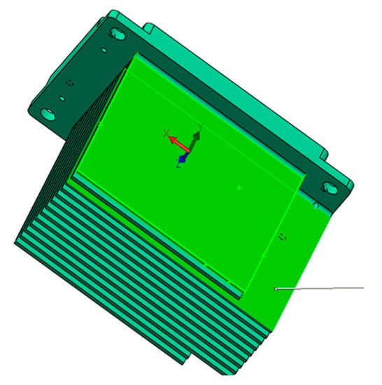
Figure 5.
Heat sink design.
The heat sink design meets thermal power absorption and dissipation requirements and, the system design is safe from thermal run-away.
3. Performance Evaluation
The final design integrated with the sensors and the signal interfaces with the actual prototype used for testing are shown in Figure 6a,b. The compact design allows mounting of the gripper onto a robot arm with a simple interface. The cooling fan and the feedback sensor board communicating with the controller are directly mounted on the heat sink. A 3D printed plastic holder holds the thermal spreader onto the Peltier module and has a shoulder to attach the membrane.
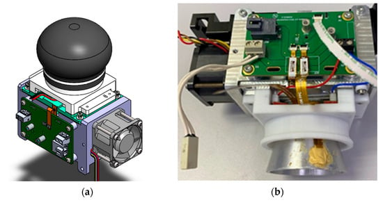
Figure 6.
(a) Final design of integrated liquid jammer; (b) prototype sample.
3.1. Molding of Membrane
Dip molding was used to make the prototype membrane. A hobby latex was used, and the mold was 3D printed. The 3D printing allows different mold designs in a quick and cost-effective way. Talcum powder is used to avoid the sticking of the latex to the mold and for easy removal without sticking onto itself. A few iterations were required to achieve the right thickness of the membrane so that it is flexible enough to wrap around the objects, yet resistant to easy rupture or leakage. Air bubbles which can rupture and cause leakage of the membrane are another challenge. This requires careful handling of the latex and slow dipping to eliminate the bubbles.
Figure 7a,b show the 3D printed mold and the dip-molded membrane.
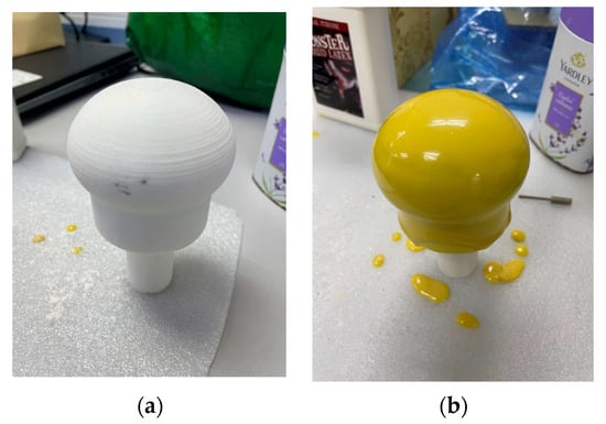
Figure 7.
Dip molding of membrane: (a) 3D-printed mold; (b) molded membrane after dipping the mold in latex.
3.2. Jamming Liquid and Properties
Virgin coconut oil was used for liquid jamming, which shows a phase transition between 20 to 10 deg from the liquid-to-solid phase. The viscosity gradually increases during this transition phase, which effectively helps to control the gripping force around the object, and the property of gradual solidification can be used for adjusting the stiffness of the grip or the holding force suited for the object. A temperature control system will be able to adapt the liquid temperature to bring it to a partially semi-solid state or solid state to suit the gripping requirements. Figure 8 shows a representative temperature vs the storage (G′) and loss moduli (G″) plot for virgin coconut oil during the liquid-to-solid and solid-to-liquid phase transition. The changes in storage and loss moduli are good indicators for the solid-to-liquid and back phase transitions.
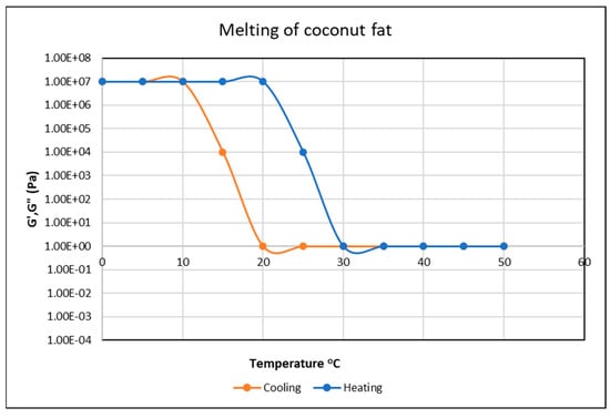
Figure 8.
Representative melting and crystallization behavior of coconut fat with temperature.
3.3. Setting up and Tuning the Controller
Venture has developed a proprietary controller that is versatile enough to control different types of motors, actuators, thermal, pneumatic systems, and TEC modules (https://apc-vest.com/products/) (accessed on 26 February 2023).
The PID control is used for controlling the liquid temperature. The fastest possible cooling and heating are required to minimize the gripping and release time. A low overshoot and undershoot are desirable to have good control on the gripping behavior. The Ziegler–Nichols method of tuning using frequency response allows a simple and efficient tuning of the controller that meets the requirements. A pure proportional gain is set (Ti = ∞ and Td = 0) and gradually increased until the system starts to oscillate. The gain when this occurs is Ku and the period of the oscillation is Tu. The recommended parameters of the controller are a factor of Ku and Tu as given in Table 4. An estimate of the period Tp of the dominant dynamics of the closed-loop system is also given in the table. Figure 9 shows the oscillation at a gain Ku of 13.5 and Tu of 8.5.

Table 4.
Controller parameters for the Ziegler–Nichols frequency response method.
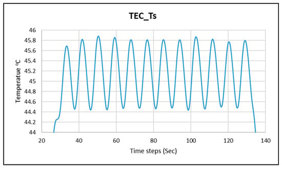
Figure 9.
Finding Ku and Tu for the system.
From the above measurements, suggested Kp, Ti, and Td are calculated as follows: Kp = 0.6 × 13.5 = 8.1; Ti = 0.5 × 8.5 = 4.3; Td = 0.125 × 8.5 = 1.1. Further optimization and tuning are achieved by trial and error around these starting values, and the performance with the optimized control parameters (Kp = 8.1, Ti = 4.3, Td = 1.4) is shown in Figure 10.
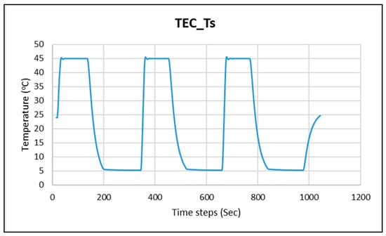
Figure 10.
Heating and cooling performance with the tuned controller.
3.4. Experimental Set up and Results
Figure 11 shows the experimental setup and jamming gripper in action. The membrane is semi-filled with about 45 gm of virgin coconut oil, and a cable tie is used to achieve a good seal for the membrane with the membrane holder to ensure the oil does not spill during the jamming action. The controller accepts multiple sensor inputs. A platinum RTD sensor bonded with thermally conductive epoxy is used to glue the sensor close to the TEC module and close to the tip of the thermal spreader. A universal serial bus connects the controller with the engineering GUI (Graphic User Interface) on the laptop. The GUI allows setting up of the PID parameters, voltage, current limits and configuring the channels. The gripper module was suspended on a string from a holding fixture. A simple lowering action of the gripper onto the object makes the membrane comply over the object. The subsequent cooling action freezes the liquid around the object. When the gripper is lifted after the solidification of the jamming liquid, the gripper lifts together with the object. Figure 12 shows the gripper lifting a cube, a plastic cup, and a jigger. The liquid jammer in action is shown in Video S1 (lifting a cup), Video S2 (lifting a cube), and Video S3 (lifting a jigger).
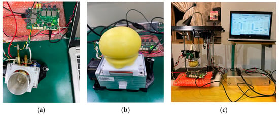
Figure 11.
Prototype: (a) spreader; (b) membrane assembled over spreader; (c) test set up.
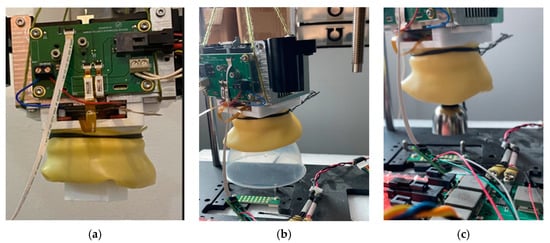
Figure 12.
Liquid jamming gripper in action. Lifting (a) a cube; (b) plastic cup by base; (c) steel jigger.
4. Discussion
The design and working of a liquid jamming gripper could be demonstrated using the prototype developed. The findings below can be considered for further work to improve the performance of the gripper.
Desirable properties for the liquid used for the jamming gripper are as follows:
- a liquid that is easily available and at low cost;
- the temperature range required for control is not wide compared to the ambient temperature and hence faster gripping and release can be achieved;
- easy to handle, non-corrosive, and compatible with the rubber used for the membrane;
- gradual solid-to-liquid transition allows control of the gripping and force applied by the gripper.
Molding membrane on a bigger scale is possible using the latex dip molding method, which is a standard method used for the manufacturing of gloves or similar latex products. Different shapes and sizes of membranes can be molded using different master molds to handle different sized and shaped objects.
The limitation of the gripper is in terms of object sizes that can be picked. Very small or flat profile objects such as a pin, paper clip, or flat and thin plate will be difficult for this gripper to pick up as the membrane may not be able to fully conform around the object to provide a satisfactory grip.
The gripping force depends on how well the membrane conforms to the shape and contour of the object and achieving a consistent picking force requires further optimization studies.
Potential rupture of the membrane and leakage of liquid is a risk and will limit the type of objects that can be picked up. An object with sharp protrusions or hard materials may pose the risk of rupture of membrane. Handling of hot objects also will be a challenge.
Another potential challenge to be solved is the condensation at low temperatures in high humidity environment. The freezing temperature of the liquid will be usually below the dew point and condensation formed over the membrane can fall on the object being gripped. However, this may not be a limitation for frozen food handling.
Time for gripping depends on how fast the liquid reaches the freezing temperature. The faster the cooling rate required, the higher will be the cooling power required and the bigger will be the size of the gripper. A trade off will be required between the size/power constraints for the gripper vs the picking time.
Gripping of bigger size objects will pose challenges due to the large volume of liquid that needs to be cooled and heated in a short time interval. In all, 40~45 gm of liquid used in the experiment could grip objects of about 2.5 mm × 2.5 mm × 2.5 mm cubes and 40 mm diameter cups. Gripping effectiveness is largely decided by the geometry, the surface texture, and weight of the object. Smooth, round objects such as marbles were difficult to grip, and the membrane failed to conform around flat and thin objects. A customized liquid jamming gripper design can address some of these issues. For example, to pick slender, tall objects, a gripper finger can be designed with liquid jamming incorporated into the finger. A single actuator two-finger gripper can be modified to have liquid jamming pockets for gripping delicate objects. The proposed design for 1-degree-of-freedom jawed robot grippers based on liquid jamming has pockets filled with jamming liquid and a Peltier as a backplate. The jaws act as heat sinks to remove the heat from the hot side of the Peltier module. The proposed design is given in Figure 13.
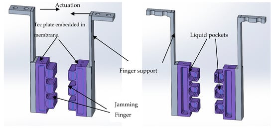
Figure 13.
Two-finger gripper design with liquid jamming pockets.
5. Conclusions
The design and testing of the liquid jamming gripper are demonstrated and can be a viable option for picking and handling of odd-shaped objects in a simple and efficient way. Using the prototype that we set up, all three functions of the liquid jammer could be demonstrated.
- Compliance/wrapping of the jammer around objects. A 3D printed cube, glass marble, flat spoon, jigger, and plastic cup were used as objects. The membrane with oil inside could comply with the form of the objects. However, the flat objects do not offer sufficient wrapping of the membrane around it and hence do not provide enough gripping force. The membrane could comply to the spherical shape of glass marble, but the smooth surface allowed the marble to slip off the gripper. A textured membrane surface could compensate for this reduced friction and can be taken up for further studies. The liquid jammer could effectively comply to the cube, plastic cup, and jigger and pick them up.
- Progressive hardening of the liquid jammer around the object by cooling. By setting the lower temperature set point (5 °C) to well below the freezing point of the oil (15 °C), complete freezing of the liquid could be ensured and a gripping force sufficient to lift the objects could be achieved. Progressive hardening of the liquid gives a gradual increase in gripping force around the object.
- Release of the object upon heating of the jamming medium. By heating the oil to about 45 °C, which is well above the melting point of oil (25 °C), the oil completely transitioned to the liquid phase and object was released successfully.
More iterations and optimizations are required to improve consistency and reliability of grip. The prototype set up can be further extended for more detailed characterization and investigations of the liquid jamming gripper. The force measurement set up is required for characterization of the gripping force and repeatability for the different objects. The design offers a potential alternative or addition to the variety of grippers being used in the field and may even offer advantages in certain industries such as frozen food handling.
6. Patents
An invention disclosure titled “Liquid Jamming Gripper” has been submitted to NUS patent office under ILO Ref: 2021-040.
Supplementary Materials
Video S1: Liquid Jammer in action: Lifting a cup, https://youtube.com/shorts/TQRr9XchRPA?feature=share (accessed on 26 February 2023); Video S2: Lifting a cube, https://youtube.com/shorts/o6bgjKE1myE?feature=share (accessed on 26 February 2023); Video S3: Lifting a jigger, https://youtube.com/shorts/dgId03YyFDA?feature=share (accessed on 26 February 2023).
Author Contributions
Conceptualization, M.P. and M.H.A.J.; methodology, M.P.; formal analysis, M.P. and M.H.A.J.; investigation, M.P.; writing—original draft preparation, M.P.; writing—review and editing, M.P. and M.H.A.J.; supervision, M.H.A.J. All authors have read and agreed to the published version of the manuscript.
Funding
This research received no external funding.
Data Availability Statement
Additional data are proprietary and cannot be shared. Please contact the corresponding author if you want additional data.
Acknowledgments
The authors wish to thank Management of Venture Corporation Ltd. for all the support given for my studies. TEC controller developed by Venture was used for thermal control and the authors wish to gratefully acknowledge Chengge Fan, who designed the TEC controller.
Conflicts of Interest
The authors declare no conflict of interest. The funders had no role in the design of the study; in the collection, analyses, or interpretation of data; in the writing of the manuscript; or in the decision to publish the results.
References
- Amend, J.; Cheng, N.; Fakhouri, S.; Culley, B. Soft Robotics Commercialization: Jamming Grippers from Research to Product. Soft Robot. 2016, 3, 213–222. [Google Scholar] [CrossRef] [PubMed]
- Simpson, D.C. Gripping Surfaces for Artificial Hands. Hand 1971, 3, 12–14. [Google Scholar] [CrossRef] [PubMed]
- Schmidt, I. Flexible moulding jaws for grippers. Ind. Robot. Int. J. Robot. Res. Appl. 1978, 5, 24–26. [Google Scholar] [CrossRef]
- Perovskii, A.P. Universal grippers for industrial robots. Russian Eng. J. 1980, 60, 3–4. [Google Scholar]
- Rienmuller, T.; Weissmantel, H. A shape adaptive gripper finger for robots. In Proceedings of the 18th International Symposium on Industrial Robots, Lausanne, Switzerland, 26–28 April 1988; pp. 241–250. [Google Scholar]
- Brown, E.; Rodenberg, N.; Amend, J.; Mozeika, A.; Steltz, E.; Zakin, M.R.; Lipson, H.; Jaeger, H.M. Universal robotic gripper based on the jamming of granular material. Proc. Natl. Acad. Sci. USA 2010, 107, 18809–18814. [Google Scholar] [CrossRef]
- Amend, J.; Lipson, H. The JamHand: Dexterous Manipulation with Minimal Actuation. Soft Robot. 2017, 4, 70–80. [Google Scholar] [CrossRef] [PubMed]
- Kapadia, J.; Yim, M. Design and performance of nubbed fluidizing jamming grippers. In Proceedings of the 2012 IEEE International Conference on Robotics and Automation, Saint Paul, MN, USA, 14–18 May 2012; pp. 5301–5306. [Google Scholar]
- Amend, J.R.; Brown, E.; Rodenberg, N.; Jaeger, H.M.; Lipson, H. A Positive Pressure Universal Gripper Based on the Jamming of Granular Material. IEEE Trans. Robot. 2012, 28, 341–350. [Google Scholar] [CrossRef]
- Fujita, M.; Tadakuma, K.; Komatsu, H.; Takane, E.; Nomura, A.; Ichimura, T.; Konyo, M.; Tadokoro, S. Jamming layered membrane gripper mechanism for grasping differently shaped-objects without excessive pushing force for search and rescue missions. Adv. Robot. 2018, 32, 590–604. [Google Scholar] [CrossRef]
- Wang, Y.; Yang, Z.; Zhou, H.; Zhao, C.; Barimah, B.; Li, B.; Xiang, C.; Li, L.; Gou, X.; Luo, M. Inflatable Particle-Jammed Robotic Gripper Based on Integration of Positive Pressure and Partial Filling. Soft Robot. 2022, 9, 309–323. [Google Scholar] [CrossRef] [PubMed]
- Tanaka, Y.; Suzuki, R.; Edamura, K.; Yokota, S. Design and Fabrication of Micro Gripper Using Functional Fluid Power. Int. J. Autom. Technol. 2022, 16, 448–455. [Google Scholar] [CrossRef]
- Götz, H.; Santarossa, A.; Sack, A.; Pöschel, T.; Müller, P. Soft particles reinforce robotic grippers: Robotic grippers based on granular jamming of soft particles. Granul. Matter 2021, 24, 1–9. [Google Scholar] [CrossRef]
- Howard, D.; O’Connor, J.; Letchford, J.; Brett, J.; Joseph, T.; Lin, S.; Furby, D.; Delaney, G.W. Getting a Grip: In Materio Evolution of Membrane Morphology for Soft Robotic Jamming Grippers. In Proceedings of the 2022 IEEE 5th International Conference on Soft Robotics (RoboSoft), Edinburgh, UK, 4–8 April 2022; pp. 531–538. [Google Scholar] [CrossRef]
- Zaidi, S.; Maselli, M.; Laschi, C.; Cianchetti, M. Actuation Technologies for Soft Robot Grippers and Manipulators: A Review. Curr. Robot. Rep. 2021, 2, 355–369. [Google Scholar] [CrossRef]
- Shan, Y.; Zhao, Y.; Pei, C.; Yu, H.; Liu, P. A novel design of a passive variable stiffness soft robotic gripper. Bioinspiration Biomim. 2022, 17, 066014. [Google Scholar] [CrossRef] [PubMed]
- Wei, H.; Shan, Y.; Zhao, Y.; Qi, L.; Zhao, X. A Soft Robot with Variable Stiffness Multidirectional Grasping Based on a Folded Plate Mechanism and Particle Jamming. IEEE Trans. Robot. 2022, 38, 3821–3831. [Google Scholar] [CrossRef]
- Tennakoon, C.L.; Kulasekera, A.L.; Chathuranga, D.S.; Gopura, R. Variable Stiffness Soft Actuator using Layer Jamming for Food Handling. In Proceedings of the 2022 Moratuwa Engineering Research Conference (MERCon), Moratuwa, Sri Lanka, 27–29 July 2022; pp. 1–6. [Google Scholar] [CrossRef]
- Adaptive Shape Gripper DHEF. Available online: https://www.festo.com/cms/en-ae_ae/69457.htm (accessed on 26 February 2023).
- Tipvarakarnkoon, T.; Blochwitz, R.; Senge, B. Rheological properties and phase change behaviors of coconut fats and oils. Annu. Trans. Nord. Rheol. Soc. 2008, 16, 159–166. [Google Scholar]
- Peltier—Thermoelectric Cooler Module Calculator. Available online: https://tetech.com/peltier-thermoelectric-cooler-module-calculator/ (accessed on 26 February 2023).
- High Performance Modules. Available online: https://tetech.com/wp-content/uploads/2019/03/HP-199-1.4-0.8.pdf (accessed on 26 February 2023).
Disclaimer/Publisher’s Note: The statements, opinions and data contained in all publications are solely those of the individual author(s) and contributor(s) and not of MDPI and/or the editor(s). MDPI and/or the editor(s) disclaim responsibility for any injury to people or property resulting from any ideas, methods, instructions or products referred to in the content. |
© 2023 by the authors. Licensee MDPI, Basel, Switzerland. This article is an open access article distributed under the terms and conditions of the Creative Commons Attribution (CC BY) license (https://creativecommons.org/licenses/by/4.0/).