Article

Real-Time Dose Monitoring via Non-Destructive Charge Measurement of Laser-Driven Electrons for Medical Applications

by
David Gregocki
1,2,
Petra Köster
1,*,
Luca Umberto Labate
1,3,*,
Simona Piccinini
1,
Federico Avella
1,2,
Federica Baffigi
1,
Gabriele Bandini
1,
Fernando Brandi
1,
Lorenzo Fulgentini
1,
Daniele Palla
1,
Martina Salvadori
1,
Simon Gerasimos Vlachos
1,2 and
Leonida Antonio Gizzi
1,3
1
Intense Laser Irradiation Laboratory, National Institute of Optics, Consiglio Nazionale delle Ricerche (CNR), Via Giuseppe Moruzzi 1, 56124 Pisa, Italy
2
Department of Physics, University of Pisa, Largo Bruno Pontecorvo 3, 56127 Pisa, Italy
3
National Institute of Nuclear Physics (INFN), Pisa Section, Largo Bruno Pontecorvo 3, 56127 Pisa, Italy
*
Authors to whom correspondence should be addressed.
Instruments 2025, 9(4), 25; https://doi.org/10.3390/instruments9040025
Submission received: 2 September 2025 / Revised: 9 October 2025 / Accepted: 11 October 2025 / Published: 23 October 2025
(This article belongs to the Special Issue Plasma Accelerator Technologies)

Abstract

Laser-accelerated electron beams, in the so-called Very High-Energy Electron (VHEE) energy range, are of great interest for biomedical applications. For instance, laser-driven VHEE beams are envisaged to offer suitable compact accelerators for the promising field of FLASH radiotherapy. Radiobiology experiments carried out using laser-driven beams require the real-time knowledge of the dose delivered to the sample. We have developed an online dose monitoring procedure, using an Integrating Current Transformer (ICT) coupled to a suitable collimator, that allows the estimation of the delivered dose on a shot-to-shot basis under suitable assumptions. The cross-calibration of the measured charge with standard offline dosimetry measurements carried out with RadioChromic Films (RCFs) is discussed, demonstrating excellent correlation between the two measurements.

1. Introduction

Advances in laser technology have allowed laser plasma accelerators (LPAs) to be experimentally explored and continuously improved. Over the past two decades, studies have led to significant progress in the quality of electron beams generated by the Laser Wakefield Acceleration [1] (LWFA) process. For instance, LWFA’s ability to produce quasimonoenergetic electron beams with energies ranging from tens of MeV to tens of GeV in just a few millimeters [2,3,4] to centimeters [5,6] brought LPAs to the attention of many scientific and industry communities. Among the most promising applications of LPAs, especially when high repetition rates are available, is radiotherapy with Very High-Energy Electron (VHEE) beams. Particularly, electron beams with kinetic energies between ∼50 and ∼300 MeV have received great interest due to their potential for improving dose conformation in radiotherapy treatments [7], reduced sensitivity to anatomical inhomogeneities [8], and ease of electromagnetic scanning in pencil beam configurations [9,10]. A growing interest in laser-driven VHEE beams is coming from the perspectives of their usage for future radiotherapy treatments exploiting the so-called FLASH effect [11]. It has been shown to have the beneficial results of lower damage to healthy tissues while maintaining biological effectiveness in cancer treatment [12,13,14]. This effect has been observed in the ultra-high dose rate regime (>40 Gy/s) [11,15], but recent studies also highlight the influence of a sufficiently high instantaneous dose rate (>10m5 Gy/s) on the activation of the FLASH effect [16]. Thus, laser-accelerated electrons may offer a unique approach to FLASH radiotherapy, as they feature ultra-high instantaneous dose rates due to their sub-picosecond duration [17] and comparable charge per bunch as “conventional” accelerators used in radiotherapy [18,19].
On the other hand, VHEE beams may be affected by a relatively limited stability in terms of energy spectrum, charge, and pointing. In a typical radiobiology study, samples are typically irradiated with a predefined dose to allow direct comparison with results from conventional irradiation. In the case of laser-driven VHEE beams, the desired dose is usually delivered by integrating over a certain number of shots of the driving laser, and the dose delivered to the sample is determined a posteriori through measurements with offline dosimeters such as RadioChromic films [20,21,22,23] (RCFs). This may lead to unwanted discrepancies between the desired dose and the actual delivered dose. Other types of dosimeters, such as alanine [22,24,25] or thermoluminescent dosimeters [26], can be cited, whose potential to cope with the ultra-high dose rate typical of LPA electrons is currently under investigation in the context of FLASH-related studies. An online-monitoring tool for the dose delivered to the sample is thus of great interest for biomedical irradiation studies.
In this article, we present a real-time dose monitoring system based on measuring the charge of the VHEE beam impinging on the sample using an Integrating Current Transformer (ICT), a widely adopted tool in the LPA community, as it allows for the non-destructive charge measurement of the electron beam with 5 pC sensitivity. However, several sources of noise can influence the ICT charge measurement. Sources of noise include electromagnetic pulses generated during the laser–matter interaction [27,28], the transmitted laser beam or energetic particles hitting the ICT, and plasma particles, such as ions and low-energy electrons, entering the ICT aperture. In two previous studies [29,30], ICT measurements on LPA-generated electron beams have been reported to overestimate the charge by more than an order of magnitude and by a factor of four, respectively, compared to image plate-based charge measurements. On the other hand, accurate charge measurements with an ICT were obtained in a successive study with the ICT placed relatively far from the laser–plasma interaction point (4.2 m) [31]. In the experimental study presented here, the ICT is used much closer to the interaction point (72 cm), with purposely designed shielding. A dedicated collimator ensured that only the charge of electrons reaching the sample was measured, and the system was calibrated using standard RCF dosimetry.
The rationale of this study stems from the fundamental relationship between bunch charge, dose, and electron flux. Under conditions specified in Section 2, the dose can be expressed in terms of the electron flux, enabling an independent estimate of bunch charge from dose measurements. We note that the dose assessment in this work only considers “thin” samples meaning that the thickness of the irradiated samples is smaller than the penetration depth of electrons whose energies correspond to the lower limit of energy spectra obtained in our experimental setup [32]. Absolute dose values can be then obtained from a calibrated ICT signal. In this work, the charge is first determined directly with the ICT and, in parallel, derived from the measured dose from the RCFs and Monte Carlo simulations. The two values are then compared. This approach not only serves to validate the reliability of ICT-based charge diagnostics but also establishes a framework for their use in real-time monitoring of VHEE beam dose delivery. In this regard, we first present the real-time dose monitoring system and a simple analytical model for the dose calculation from the charge measurement in Section 2. In Section 3 we describe the experimental measurements for the calibration of the dose monitoring system with standard RCF dose measurements. We then discuss the experimental results and the validity of using ICT as an online dose monitoring system. Conclusions are drawn in the last section, Section 4.

2. Real-Time Dose Monitoring System

In this section we briefly present a simple analytical model for the calculation of dose from the charge measurement with the real-time dose monitoring system. The system consists of an ICT equipped with a collimator with an opening diameter equal to the size of the sample to be irradiated. The charge measurement performed with the ICT on the VHEE beam passing through the collimator aperture can be related to the dose delivered to the sample due to the characteristics of the electron interaction with matter. Electrons with energies above ∼30 MeV deliver on a thin layer of material a dose/electron nearly independent of their initial kinetic energy [23,33]. Therefore, for VHEE beams the dose is proportional to the electron flux and thus also the charge. As stated in the previous section, this holds true over a depth smaller than the penetration depth of the electrons. To compare the ICT charge measurement with the dose measured by the RCFs as described in the following section, we use a simple analytical model. The collisional stopping power that considers only energy losses with energy transfer to the secondary particle lower than a given value Δ is called the restricted collisional stopping power. In this regard, the dose delivered by VHEE beams to the RCF can be approximated by the formula
D = E min E max S ρ Δ coll ( E ) · Φ ( E ) d E ,
where E is the primary electron kinetic energy, Φ ( E ) is the electron flux, S ρ Δ coll ( E ) is the restricted collisional stopping power, and D is the deposited dose. The integral is performed over the spectral range of the electron beam. In this formula, the kinetic energy of the primary electron is considered constant over the propagation distance, which is a good approximation for our experimental conditions, as the VHEE electrons lose only a few keV of energy over the active layer thickness of the RCF in the experimental setup.

3. Calibration of Dose Monitoring System with Standard RCF Dosimetry

In this section we report on the cross-calibration of the real-time dose monitoring system based on the ICT charge measurements using standard dosimetric techniques employing RCF. The experimental studies were conducted in the target area of ILIL’s 220 TW laser system at CNR-INO [34], capable of delivering up to 5 J laser pulses on a target. The experimental setup is illustrated in Figure 1. As shown, ultra-short laser pulses are focused by an Off-Axis Parabolic (OAP) mirror into a supersonic gas jet (99% He + 1% N2) generated via a cylindrical nozzle with a 2 mm diameter with a 4 bar backing pressure.
Electron beams generated during the laser–plasma interaction propagated 58 cm in vacuum. Afterwards, electron beams passed through a 13 μ m thick aluminum foil attached to the 75 μ m thick vacuum window (Mylar) on the vacuum side to shield the co-propagating remnant laser pulse. From outside the vacuum chamber, a scintillating screen (Regular Lanex, Carestream) was fixed to the vacuum window. Alignment tests prior to the RCF irradiations showed stable electron beam pointings of σ x 3.6 mrad and σ y 2.9 mrad at the vacuum–air entrance window and average FWHM beam sizes of S Hor 0.98 cm and S Ver 0.73 cm (see Supplementary Material). After the aluminum foil, vacuum window, and Lanex screen, the electron bunch passed through the collimator and the ICT (ICT-028-070-5.0-LD-VAC-H, Bergoz) with a sensitivity of 10 mV/pC, placed 15 cm away from the vacuum window. As can be seen from Figure 2, the ICT was put inside a PolyLactic Acid (PLA) cover, designed with the open-source software Blender® 3.6.5 and 3D printed for easy mounting, partial shielding, and collimation of incoming electrons. The front collimating part is 5 cm thick with an inner diameter of 1.45 cm and made of PVC-based material employed to reduce noise that originates from scattered, more divergent, and low-energy electrons while minimizing hard X-ray emissions from Bremsstrahlung. As the collimator consists of a non-conducting material, potential influences on the electron beam resulting from charge buildup were taken into account. As for charging occurring over a single shot, a very simplified estimate, treating the collimator as a simple cylindrical capacitor, indicates that the electric field would result in very weak focusing (lateral displacement of less than 5 μ m over 1 m of propagation). Concerning cumulative effects over multiple shots, we observe that experiments of this type are typically characterized by relatively low average beam currents, with electron beam charges of the order of ∼10–100s of pC and repetition rates on the order of Hz. Under such conditions, the amount of deposited charge on the collimator is negligible, and any resulting perturbation of the subsequent electron beam is expected to be insignificant. Accordingly, no cumulative perturbation of the electron beam was observed during the experiment, even after several hundred shots. The internal surface of the ICT was lined with 0.43 cm thick PLA plastic to ensure partial isolation from the elements. The diameter of the ICT was d = 1.93 cm.
The connection between the ICT and its controller (BCM-IHR-E, Bergoz, Saint Genis Pouilly, France), placed at a large distance and separated by a 33 cm thick barite concrete shielding wall, was provided by a coaxial cable that was externally braided with a grounded metallic shield. A mirror was placed 56 cm away from the ICT. The reflecting image was captured by a CCD camera fixed at a 32 cm distance from the mirror. As a result, it was possible to assess at any time during the experiment the electron beam pointing with respect to the ICT based on the Lanex emission signal reflected from the mirror and captured by the CCD camera.
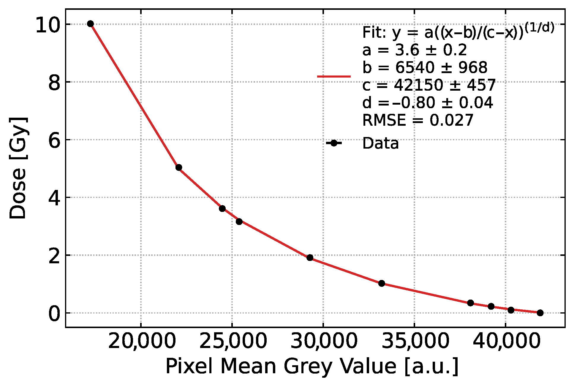
For the sake of this calibration experiment, a single RCF (GAFChromic EBT3, Ashland, Bridgewater, NJ, USA) strip was attached to the rear part of the ICT cover and replaced with a new one after 10 consecutive single-shot irradiations by the passing electron beams. This allowed for the simultaneous measurement of the electron charge and their deposited dose to the RCF. After the irradiation, a Magnetic Dipole (MD) with the Lanex screen was placed in the electron beam path to measure the energy distribution of electrons. Irradiated RCFs were scanned with the same orientation [35] and position [36] with respect to the scanning surface of a flatbed scanner (Perfection V600 Photo, Epson, Amsterdam, The Netherlands) 24 h after the exposure to account for the post-exposure changes [37]. RGB positive scans were collected with 45-bit depth resolution per color channel with a spatial resolution of 150 dpi, without any additional color enhancements. Afterwards, scanned RCFs were analyzed in the red channel for better sensitivity [38], while the Gray Value (GV) of each pixel was retrieved from an irradiated region of fixed diameter that corresponds to the effective diameter of the ICT. Each GV per pixel was converted to dose and subsequently averaged. EBT3 RCF films were calibrated in advance using 9 MeV clinical electron beams produced by the ElectronFlash LINAC at Hospital Santa Chiara (Pisa). The pixel Mean Gray Value (MGV) was extracted from the red channel and directly employed for calibration, without conversion to net optical density, to maintain a consistent scanning workflow. The calibration curve, see Figure 3, was obtained by fitting the delivered dose against the corresponding MGV values using the NIH Rodbard four-parameter function [39], with weighted least squares having weights derived from the standard deviation of the three replicate films.

3.1. Experimental Calibration of Dose Versus Charge

In this subsection we report the results of the experimental measurements aimed at finding the actual relationship between the charge and the dose. To this purpose, a total of 40 shots in four sets of 10 shots were used. The corresponding charge values, measured by the ICT Q ICT are displayed in Table 1. In our experimental conditions, the shot-to-shot variations of the charge are due in part to variations of the electron beam charge, but the main contribution also stems from the beam pointing variations.
The RCF strips placed behind the ICT were replaced after each set of 10 shots. The 2D dose maps retrieved from the RCF strips are shown in Figure 4. The average dose values retrieved from each of the four RCF strips are shown at the bottom of Table 1. To correlate the measurement of the ICT charge with the dose measurement performed with the RCF, the sum of the charges of each set of ten shots is computed. The dose of each set is plotted against this sum in Figure 5, from which a strong correlation can be observed between the measured charge and dose, as expected from theory. Such a correlation is in agreement with previous studies in which LINACs [40,41,42] or laser-driven ion accelerators [43] were used as a particle source together with an alanine dosimeter [41].
The regression line with two degrees of freedom, retrieved in the correlation analysis, can be expressed as
D [ Gy ] = 2.4 × 10 4 · Q ICT [ pC ] 2.0 × 10 4 ,
where the non-zero intercept value, with no physical meaning, is attributed to uncertainties arising during the calibration procedure of the RCFs, such as the intrinsic sensitivity of the films, the reading sensitivity and reproducibility of the scanner, or for that matter, the sensitivity of the ICT. The deviations of the measured dose with respect to the dose calculated from the calibration formula, in Equation (2), are at most 3.2 %, showing that the dose delivered to the sample can be estimated from the charge measurements with a few percent accuracy. The system is therefore suitable to monitor the dose delivered to a sample in real-time during the irradiation with the VHEE beams.

3.2. Cross-Validation of the Dose Monitoring System

In order to cross-check the validity of the relationship between the charge measured through the ICT and the dose, the measured dose values can be used to retrieve the RCF charge corresponding to that dose via Equation (1), and then compared with the ICT measurements. This requires inverting Equation (1) and applying suitable assumptions to derive the RCF charge from the flux, as detailed in what follows.
Starting from Equation (1), derived in Section 2, the relation between the measured dose from the RCF expressed in Gy and the electron fluence on the RCF ϕ RCF ( E ) expressed in cm−2 is given by
D E min E max D ( E ) d E = K S ρ Δ coll ( E ) · ϕ RCF ( E ) d E ,
where S ρ Δ coll ( E ) is the energy-dependent restricted mass collisional stopping power expressed in MeV·cm2 · g−1. From now on, when referring to the collisional stopping power, we will intend the restricted mass collisional stopping power. The constant K = 1.6 × 10 10 represents a conversion factor used to convert MeV·g−1 in Gy and the integral is performed over the spectral range of the electrons.
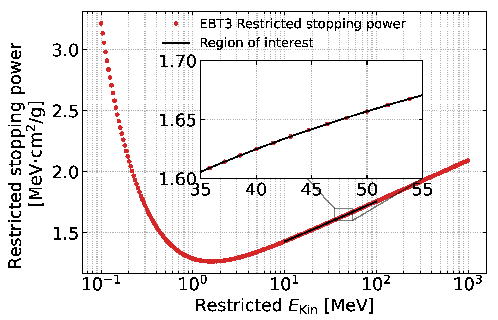
The energy spectrum of electrons that propagated through the ICT was measured with a magnetic dipole spectrometer placed behind it, following the procedure described in the recently accepted article [44]. The obtained result is shown in Figure 6. The spectrum shows a peak around 42 MeV and a spectral FWHM of about 17 MeV. The collisional stopping power, displayed in Figure 7, was calculated using the formula derived from the Bethe soft-collision stopping power and the Møller hard-collision stopping power [45], considering the composition of the EBT3’s active layer [46], shown in Table 2.
In the inset of Figure 7, the region of the stopping power relevant to the electron spectral range in our experimental conditions is shown in more detail. In this range the stopping power has a nearly constant value. Therefore, it is possible to rewrite Equation (3) using the weighted average of the stopping power, weighted by the energy spectra values y depicted in Figure 6, i.e.,
S - ρ = E min E max w ( E ) · S ρ Δ coll ( E ) d E w ( E ) = y ( E ) E min E max y ( E ) d E .
Therefore, Equation (3) can be rewritten as
ϕ Total RCF E min E max ϕ RCF ( E ) d E = D K · S - ρ .
Ultimately, substituting the accumulated dose D from the experiment, depicted in Table 1, together with K and weighted S - ρ 1.633 ± 0.023 MeV·cm2 · g−1, into Equation (5), ϕ Total RCF can be retrieved.
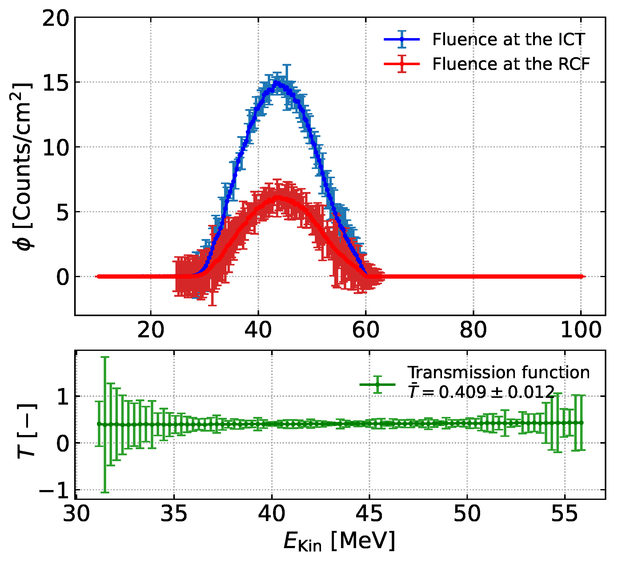
The electron beam divergence and scattering in the materials encountered, such as the 13 μ m thick aluminum foil, 75 μ m thick vacuum window, and the Lanex screen, cause the electron fluence to decrease over the beam propagation from the interaction point to the ICT and finally to the RCF [44]. For this reason, Monte Carlo simulations were performed using the FLUKA code [47,48] to determine the ratio T, further referred to as the transmission function, between electron fluences that will reach the ICT and the RCF.
Simulation parameters such as the distance between the ICT, RCF, and the entrance window were set to be the same as during the experiment while taking into account both the aluminum foil and the Lanex screen placed at the entrance window. In order to obtain good statistical accuracy per energy bin of finite width denoted with the index i, an electron beam consisting of 6 × 10 5 primary particles was considered. The spectrum of the primary particles was retrieved by the experimental one (see Figure 6), corrected for the effects due to the propagation through the different elements (including vacuum, Al foil, vacuum window, and air) from the source up to the magnetic dipole; to this purpose, the FLUKA code was used to retrieve the flux on the dipole at selected energy bins. Such a procedure resulted in a “transfer function,” which was used to backpropagate the measured spectrum for this purpose. The energy-dependent electron fluences ϕ i were retrieved at the position of the ICT and the RCF strip, while their ratio was calculated to obtain the transmission function T i for which ϕ Total RCF = i T i ϕ i ICT and T i 1 i . Based on the results depicted in Figure 8, T can be approximated with relatively high accuracy as a constant value, defined as an average T ¯ = 0.409 ± 0.012 . Such a value of T ¯ is consistent with the recent study [44] showing that upstream components, particularly the Lanex screen, induce scattering and divergence growth, perturbing electron trajectories and reducing the fraction of electrons that reach the downstream RCF after the ICT.
Eventually, one can rewrite ϕ Total RCF = T ¯ · ϕ Total ICT by using the equation
Q RCF = ϕ Total RCF T ¯ · d 2 2 · π · e ,
where e is the elementary charge. Therefore, it is possible to obtain the electron beam charge Q RCF , from the knowledge of the deposited dose to the RCF strip, i.e., using Equation (5), and T ¯ . The results are shown for each irradiated RCF in Table 3.
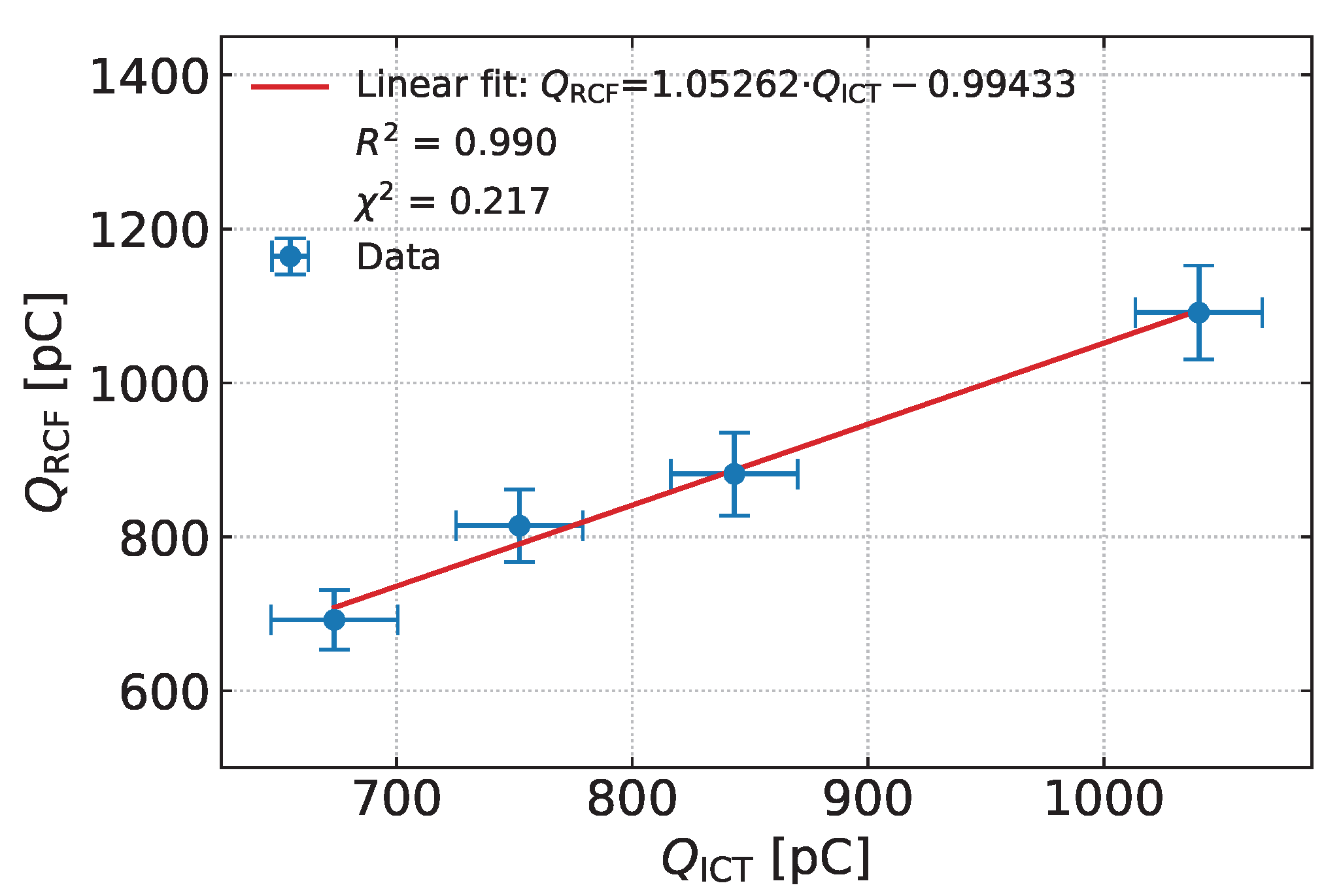
Comparing these results with the charge measured by the ICT as shown in Figure 9, it is evident that the two measurements are consistent. It should be noted that for significant changes in the electron energy range, the calibration of the dose monitoring system will change. The new calibration formula can then be calculated from the stopping power and the transmission curve.

4. Conclusions

Laser plasma accelerators are gradually gaining importance in the medical field as radiation sources for innovative FLASH radiotherapy due to their capability of producing Very High-Energy Electron (VHEE) beams. Given the strict conditions put on the quality of the generated electron beams with the requirement of delivering a dose to the target, non-invasive beam diagnostic devices are required. Therefore, we have developed a real-time dose monitoring system based on a charge measurement with an integrating current transformer equipped with a collimator with an aperture corresponding to the sample transverse dimensions. After calibration, the system is suited to monitor with a few percent accuracy the dose delivered to a sample whose thickness is assumed to be less than the penetration depth of electrons at the lowest energies measured in our setup. Further developments include the possibility to access calibration based on a single shot, rather than averaging multiple shots. This will require replacing radiochromic film with a more sensitive dosimetric detector to capture dose on a single shot. Our study ultimately provides direct access to dose monitoring to be implemented in future preclinical and clinical settings based on laser-driven VHEE radiotherapy devices.

Supplementary Materials

The following supporting information can be downloaded at: https://www.mdpi.com/article/10.3390/instruments9040025/s1, Figure S1: Electron beam pointing prior to RCF irradiation. The captured signal originates from the Lanex screen placed at the vacuum–air entrance window, imaging through the collimator and ICT aperture. These images represent a subset of the data used to estimate the electron beam pointing, from which values of σ x 3.6 mrad and σ y 2.9 mrad at the entrance window (58 cm away from the laser-plasma interaction) were retrieved. Figures (B) and (F) show minimal light yield from the Lanex, while figures (E) and (H) indicate a portion of the electron beam hitting the ICT collimator.; Figure S2: Correlation between the integrated density signal from Lanex and the corresponding single-shot ICT measured charge. Measured data labeled as "low light yield at Lanex" (grey dots) correspond to figures (B) and (F) in Figure S1, while data labeled as "collimator hit" (red dots) correspond to figures (E) and (H). Integration area of the Lanex signal corresponds to diameter of d = 1.93 cm.; Figure S3: Extracted horizontal and vertical 1D dose profiles through the ICT aperture center from the 2D dose maps reported in Figure 4 of the main article; FLUKA Simulation parameters.

Author Contributions

Conceptualization, D.G., P.K., and L.U.L.; methodology, D.G. and P.K.; software, D.G., S.G.V., and F.A.; validation, all authors contributed equally; formal analysis, D.G., P.K., L.U.L. and S.G.V.; investigation, all authors contributed equally; resources, all authors contributed equally; data curation, D.G. and P.K.; writing—original draft preparation, D.G.; writing—review and editing, all authors contributed equally; visualization, D.G.; supervision, P.K. and L.U.L.; project administration, L.U.L. and L.A.G.; funding acquisition, L.U.L. and L.A.G. All authors have read and agreed to the published version of the manuscript.

Funding

The authors acknowledge funding from the European Union’s Horizon Europe research and innovation program and the UKRI guarantee funds through the MSCA “EuPRAXIA Doctoral Network”-EuPRAXIA-DN, under Grant Agreement No. 101073480, and additional financial support from the following research programs: EU Horizon 2020 Research and Innovation Program EuPRAXIA Preparatory Phase, under Grant Agreement No. 101079773, and EU Horizon IFAST, under Grant Agreement No. 101004730. This research has been co-funded by the European Union-NextGeneration EU through the Italian PNRR MUR projects “Integrated infrastructure initiative in Photonic and Quantum Sciences”-I-PHOQS (IR0000016, ID D2B8D520, CUP B53C22001750006); “EuPRAXIA Advanced Photon Sources”-EuAPS (IR0000030, CUP I93C21000160006); “Tuscany Health Ecosystem(THE)-Spoke 1: Advanced Radiotherapies and Diagnostics in Oncology” (ECS00000017, D.D. MUR No. 1055 23 May 2022); and the Italian INFN CSN5-funded project FRIDA.

Data Availability Statement

Data will be made available upon reasonable request.

Conflicts of Interest

The authors declare no conflicts of interest.

References

  1. Tajima, T.; Dawson, J.M. Laser Electron Accelerator. Phys. Rev. Lett. 1979, 43, 267–270. [Google Scholar] [CrossRef]
  2. Mangles, S.P.D.; Murphy, C.D.; Najmudin, Z.; Thomas, A.G.R.; Collier, J.L.; Dangor, A.E.; Divall, E.J.; Foster, P.S.; Gallacher, J.G.; Hooker, C.J.; et al. Monoenergetic beams of relativistic electrons from intense laser–plasma interactions. Nature 2004, 431, 535–538. [Google Scholar] [CrossRef]
  3. Geddes, C.G.R.; Toth, C.; van Tilborg, J.; Esarey, E.; Schroeder, C.B.; Bruhwiler, D.; Nieter, C.; Cary, J.; Leemans, W.P. High-quality electron beams from a laser wakefield accelerator using plasma-channel guiding. Nature 2004, 431, 538–541. [Google Scholar] [CrossRef] [PubMed]
  4. Faure, J.; Glinec, Y.; Pukhov, A.; Kiselev, S.; Gordienko, S.; Lefebvre, E.; Rousseau, J.P.; Burgy, F.; Malka, V. A laser–plasma accelerator producing monoenergetic electron beams. Nature 2004, 431, 541–544. [Google Scholar] [CrossRef] [PubMed]
  5. Leemans, W.P.; Nagler, B.; Gonsalves, A.J.; Toth, C.; Nakamura, K.; Geddes, C.G.R.; Esarey, E.; Schroeder, C.B.; Hooker, S.M. GeV electron beams from a centimetre-scale accelerator. Nat. Phys. 2006, 2, 696–699. [Google Scholar] [CrossRef]
  6. Nakamura, K.; Nagler, B.; Toth, C.; Geddes, C.G.R.; Schroeder, C.B.; Esarey, E.; Leemans, W.P.; Gonsalves, A.J.; Hooker, S.M. GeV electron beams from a centimeter-scale channel guided laser wakefield accelerator. Phys. Plasmas 2007, 14, 056708. [Google Scholar] [CrossRef]
  7. Labate, L.; Andreassi, M.G.; Baffigi, F.; Bizzarri, R.; Borghini, A.; Bussolino, G.C.; Fulgentini, L.; Ghetti, F.; Giulietti, A.; Köster, P.; et al. TLESM: A laser-driven sub-MeV electron source delivering ultra-high dose rate on thin biological samples. J. Phys. D Appl. Phys. 2016, 49, 275401. [Google Scholar] [CrossRef]
  8. Lagzda, A.; Angal-Kalinin, D.; Jones, J.; Aitkenhead, A.; Kirkby, K.J.; MacKay, R.; Herk, M.V.; Farabolini, W.; Zeeshan, S.; Jones, R.M. Influence of heterogeneous media on Very High Energy Electron (VHEE) dose penetration and a Monte Carlo-based comparison with existing radiotherapy modalities. Nucl. Instrum. Methods Phys. Res. B. 2020, 482, 70–81. [Google Scholar] [CrossRef]
  9. Labate, L.; Palla, D.; Panetta, D.; Avella, F.; Baffigi, F.; Brandi, F.; Martino, F.D.; Fulgentini, L.; Giulietti, A.; Köster, P.; et al. Toward an effective use of laser-driven very high energy electrons for radiotherapy: Feasibility assessment of multi-field and intensity modulation irradiation schemes. Sci. Rep. 2020, 10, 17307. [Google Scholar] [CrossRef]
  10. Panaino, C.M.V.; Piccinini, S.; Andreassi, M.G.; Bandini, G.; Borghini, A.; Borgia, M.; Naro, A.D.; Labate, L.; Maggiulli, E.; Portaluri, M.G.A.; et al. Very High-Energy Electron Therapy Toward Clinical Implementation. Cancers 2025, 17, 181. [Google Scholar] [CrossRef]
  11. Favaudon, V.; Caplier, L.; Monceau, V.; Pouzoulet, F.; Sayarath, M.; Fouillade, C.; Poupon, M.F.; Brito, I.; Hupe, P.; Bourhis, J.; et al. Ultrahigh dose-rate FLASH irradiation increases the differential response between normal and tumor tissue in mice. Sci. Transl. Med. 2014, 6, 245ra93. [Google Scholar] [CrossRef]
  12. Montay-Gruel, P.; Petersson, K.; Jaccard, M.; Boivin, G.; Germond, J.F.; Petit, B.; Doenlen, R.; Favaudon, V.; Bochud, F.; Bourhis, C.B.J.; et al. Irradiation in a flash: Unique sparing of memory in mice after whole brain irradiation with dose rates above 100Gy/s. Radiother. Oncol. 2017, 124, 365–369. [Google Scholar] [CrossRef]
  13. Montay-Gruel, P.; Acharya, M.M.; Petersson, K.; Alikhani, L.; Yakkala, C.; Allen, B.D.; Ollivier, J.; Petit, B.; Jorge, P.G.; Syage, A.R.; et al. Long-term neurocognitive benefits of FLASH radiotherapy driven by reduced reactive oxygen species. Proc. Natl. Acad. Sci. USA 2019, 116, 10943–10951. [Google Scholar] [CrossRef]
  14. Vozenin, M.C.; Fornel, P.D.; Petersson, K.; Favaudon, V.; Jaccard, M.; Germond, J.F.; Petit, B.; Burki, M.; Ferrand, G.; Patin, D.; et al. The Advantage of FLASH Radiotherapy Confirmed in Mini-pig and Cat-cancer Patients. Clin. Cancer Res. 2019, 25, 35–42. [Google Scholar] [CrossRef]
  15. Bourhis, J.; Sozzi, W.J.; Jorge, P.G.; Gaide, O.; Bailat, C.; Duclos, F.; Patin, D.; Ozsahin, M.; Bochud, F.; Germond, J.F.; et al. Treatment of a first patient with FLASH-radiotherapy. Radiother. Oncol. 2019, 139, 18–22. [Google Scholar] [CrossRef] [PubMed]
  16. Zhu, H.; Liu, S.; Qiu, J.; Hu, A.; Zhou, W.; Wang, J.; Gu, W.; Zhu, Y.; Zha, H.; Xiang, R.; et al. Instantaneous dose rate as a crucial factor in reducing mortality and normal tissue toxicities in murine total-body irradiation: A comparative study of dose rate combinations. Mol. Med. 2025, 31, 79. [Google Scholar] [CrossRef]
  17. Esarey, E.; Schroeder, C.B.; Leemans, W.P. Physics of laser-driven plasma-based electron accelerators. Rev. Mod. Phys. 2009, 81, 1229–1285. [Google Scholar] [CrossRef]
  18. Laschinsky, L.; Baumann, M.; Beyreuther, E.; Enghardt, W.; Kaluza, M.; Karsch, L.; Lessmann, E.; Naumburger, D.; Nicolai, M.; Richter, C.; et al. Radiobiological Effectiveness of Laser Accelerated Electrons in Comparison to Electron Beams from a Conventional Linear Accelerator. J. Radiat. Res. 2012, 53, 395–403. [Google Scholar] [CrossRef]
  19. Vojnovic, B.; Tullis, I.D.C.; Newman, R.G.; Petersson, K. Monitoring beam charge during FLASH irradiations. Front. Phys. 2023, 11, 1185237. [Google Scholar] [CrossRef]
  20. Arjomandy, B.; Tailor, R.; Zhao, L.; Devic, S. EBT2 film as a depth-dose measurement tool for radiotherapy beams over a wide range of energies and modalities. Med. Phys. 2012, 39, 912–921. [Google Scholar] [CrossRef]
  21. Sipila, P.; Ojala, J.; Kaijaluoto, S.; Jokelainen, I.; Kosunen, A. Gafchromic EBT3 film dosimetry in electron beams-energy dependence and improved film read-out. J. Appl. Clin. Med. Phys. 2016, 17, 360–373. [Google Scholar] [CrossRef]
  22. Kokurewicz, K.; Schüller, A.; Brunetti, E.; Subiel, A.; Kranzer, R.; Hackel, T.; Meier, M.; Kapsch, R.P.; Jaroszynski, D.A. Dosimetry for New Radiation Therapy Approaches Using High Energy Electron Accelerators. Front. Phys. 2020, 8, 568302. [Google Scholar] [CrossRef]
  23. Clements, N.; Bazalova-Carter, M. Monte Carlo calculated absorbed-dose energy dependence of EBT3 and EBT4 films for 5–200 MeV electrons and 100 keV–15 MeV photons. J. Appl. Clin. Med. Phys. 2024, 25, 14529. [Google Scholar] [CrossRef] [PubMed]
  24. Fainstein, C.; Winkler, E.; Saravi, M. ESR/Alanine γ-dosimetry in the 10–30 Gy range. Appl. Radiat. Isot. 2000, 52, 1195–1196. [Google Scholar] [CrossRef] [PubMed]
  25. Gondre, M.; Jorge, P.G.; Vozenin, M.C.; Bourhis, J.; Bochud, F.; Bailat, C.; Moeckli, R. Optimization of Alanine Measurements for Fast and Accurate Dosimetry in FLASH Radiation Therapy. Radiat. Res. 2020, 194, 573–579. [Google Scholar] [CrossRef]
  26. Francescon, P.; Kilby, W.; Noll, J.M.; Masi, L.; Satariano, N.; Russo, S. Monte Carlo simulated corrections for beam commissioning measurements with circular and MLC shaped fields on the CyberKnife M6 System: A study including diode, microchamber, point scintillator, and synthetic microdiamond detectors. Phys. Med. Biol. 2017, 62, 1076. [Google Scholar] [CrossRef]
  27. Consoli, F.; De-Angelis, R.; Andreoli, P.; Cipriani, M.; Cristofari, G.; Giorgio, G.D.; Ingenito, F. Experiments on electromagnetic pulse (EMP) generated by laser-plasma interaction in nanosecond regime. In Proceedings of the 2015 IEEE 15th International Conference on Environment and Electrical Engineering (EEEIC), Rome, Italy, 10–13 June 2015; pp. 182–187. [Google Scholar] [CrossRef]
  28. He, Q.Y.; Yan, W.; Liu, Z.P.; Yan, Y.; Fang, Y.L.; Li, C.T.; Wu, Q.F.; Song, T.; Li, T.S.; Lin, C.; et al. Measurement of electromagnetic pulse in laser acceleration enhanced by near-critical density targets. Phys. Plasmas 2024, 31, 103303. [Google Scholar] [CrossRef]
  29. Glinec, Y.; Faure, J.; Guemnie-Tafo, A.; Malka, V.; Monard, H.; Larbre, J.P.; Waele, V.D.; Marignier, J.L.; Mostafavi, M. Absolute calibration for a broad range single shot electron spectrometer. Rev. Sci. Instrum. 2006, 77, 103301. [Google Scholar] [CrossRef]
  30. Hidding, B.; Pretzler, G.; Clever, M.; Brandl, F.; Zamponi, F.; Lubcke, A.; Kampfer, T.; Uschmann, I.; Forster, E.; Schramm, U.; et al. Novel method for characterizing relativistic electron beams in a harsh laser-plasma environment. Rev. Sci. Instrum. 2007, 78, 083301. [Google Scholar] [CrossRef]
  31. Nakamura, K.; Gonsalves, A.J.; Lin, C.; Smith, A.; Rodgers, D.; Donahue, R.; Byrne, W.; Leemans, W.P. Electron beam charge diagnostics for laser plasma accelerators. Phys. Rev. ST Accel. Beams 2011, 14, 062801. [Google Scholar] [CrossRef]
  32. Lazurik, V.; Moskvin, V.; Tabata, T. Average depths of electron penetration: Use as characteristic depths of exposure. IEEE Trans. Nucl. Sci. 1997, 45, 626–631. [Google Scholar] [CrossRef]
  33. Galimberti, M.; Giulietti, A.; Giulietti, D.; Gizzi, L.A. SHEEBA: A spatial high energy electron beam analyzer. Rev. Sci. Instrum. 2005, 76, 053303. [Google Scholar] [CrossRef]
  34. Gizzi, L.A.; Labate, L.; Baffigi, F.; Brandi, F.; Bussolino, G.; Fulgentini, L.; Koster, P.; Palla, D. Overview and specifications of laser and target areas at the Intense Laser Irradiation Laboratory. High Power Laser Sci. Eng. 2021, 9, e10. [Google Scholar] [CrossRef]
  35. Paelinck, L.; Ebongue, A.; Neve, W.D.; Wagter, C.D. Radiochromic EBT film dosimetry: Effect of film orientation and batch on the lateral correction of the scanner. Radiother. Oncol. 2007, 84, 194–195. [Google Scholar]
  36. Chung, H.; Lynch, B.; Samant, S. High-precision GAFCHROMIC EBT film-based absolute clinical dosimetry using a standard flatbed scanner without the use of a scanner non-uniformity correction. J. Appl. Clin. Med. Phys. 2010, 11, 3112. [Google Scholar] [CrossRef]
  37. Ali, I.; Costescu, C.; Vicic, M.; Dempsey, J.F.; Williamson, J.F. Dependence of radiochromic film optical density post-exposure kinetics on dose and dose fractionation. Med. Phys. 2003, 30, 1958–1967. [Google Scholar] [CrossRef] [PubMed]
  38. Papaconstadopoulos, P.; Hegyi, G.; Seuntjens, J.; Devic, S. A protocol for EBT3 radiochromic film dosimetry using reflection scanning. Med. Phys. 2014, 41, 122101. [Google Scholar] [CrossRef]
  39. Howard, M.E.; Herman, M.G.; Grams, M.P. Methodology for radiochromic film analysis using FilmQA Pro and ImageJ. PLoS ONE 2020, 15, 1–12. [Google Scholar] [CrossRef] [PubMed]
  40. Jorge, P.G.; Grilj, V.; Bourhis, J.; Vozenin, M.C.; Germond, J.F.; Bochud, F.; Bailat, C.; Moeckli, R. Technical note: Validation of an ultrahigh dose rate pulsed electron beam monitoring system using a current transformer for FLASH preclinical studies. Med. Phys. 2022, 49, 1831–1838. [Google Scholar] [CrossRef] [PubMed]
  41. Kranzer, R.; Schuller, A.; Bourgouin, A.; Hackel, T.; Poppinga, D.; Lapp, M.; Looe, H.K.; Poppe, B. Response of diamond detectors in ultra-high dose-per-pulse electron beams for dosimetry at FLASH radiotherapy. Phys. Med. Biol. 2022, 67, 075002. [Google Scholar] [CrossRef]
  42. Oesterle, R.; Jorge, P.G.; Grilj, V.; Bourhis, J.; Vozenin, M.C.; Germond, J.F.; Bochud, F.; Bailat, C.; Moeckli, R. Implementation and validation of a beam-current transformer on a medical pulsed electron beam LINAC for FLASH-RT beam monitoring. J. Appl. Clin. Med. Phys. 2021, 22, 165–171. [Google Scholar] [CrossRef]
  43. Geulig, L.D.; Obst-Huebl, L.; Nakamura, K.; Bin, J.; Ji, Q.; Steinke, S.; Snijders, A.M.; Mao, J.H.; Blakely, E.A.; Gonsalves, A.J.; et al. Online charge measurement for petawatt laser-driven ion acceleration. Rev. Sci. Instrum. 2022, 93, 103301. [Google Scholar] [CrossRef] [PubMed]
  44. Vlachos, S.G.; Labate, L.; Baffigi, F.; Bandini, G.; Brandi, F.; Fulgentini, L.; Gregocki, D.; Köster, P.; Palla, D.; Piccinini, S.; et al. Single-shot spectrometer with pointing angle correction for laser-driven electron beams featuring pointing instability and transverse inhomogeneity. Nucl. Instrum. Methods Phys. Res. A 2026, 1082, 171038. [Google Scholar] [CrossRef]
  45. McParland, B.J. Medical Radiation Dosimetry; Springer: London, UK, 2013; Chapter 10; Available online: https://link.springer.com/book/10.1007/978-1-4471-5403-7 (accessed on 18 August 2025).
  46. Palmer, A.L.; Dimitriadis, A.; Nisbet, A.; Clark, C.H. Evaluation of Gafchromic EBT-XD film, with comparison to EBT3 film, and application in high dose radiotherapy verification. Phys. Med. Biol. 2015, 60, 8741. [Google Scholar] [CrossRef] [PubMed]
  47. Ahdida, C.; Bozzato, D.; Calzolari, D.; Cerutti, F.; Charitonidis, N.; Cimmino, A.; Coronetti, A.; D’Alessandro, G.L.; Servelle, A.D.; Esposito, L.S.; et al. New Capabilities of the FLUKA Multi-Purpose Code. Front. Phys. 2022, 9, 788253. [Google Scholar] [CrossRef]
  48. Battistoni, G.; Boehlen, T.; Cerutti, F.; Chin, P.W.; Esposito, L.S.; Fasso, A.; Ferrari, A.; Lechner, A.; Empl, A.; Mairani, A.; et al. Overview of the FLUKA code. Ann. Nucl. Energy 2015, 82, 10–18. [Google Scholar] [CrossRef]
Figure 1. Schematic of the experimental setup. Transporting mirrors are described with the letter M.
Instruments 09 00025 g001
Figure 2. ICT cover with a PVC-based collimator and a PLA-based enclosure.
Instruments 09 00025 g002
Figure 3. Calibration curve of EBT3 RCF films, showing dose versus mean pixel gray value.
Instruments 09 00025 g003
Figure 4. Two-dimensional dose maps of RCF strips irradiated by 10 consecutive electron beams each.
Instruments 09 00025 g004
Figure 5. Summed electron charge Q ICT , measured by the ICT during 10 consecutive single shots in 4 sets, expressed as a function of the accumulated dose D deposited to the corresponding RCF.
Instruments 09 00025 g005
Figure 6. Graph of the electron kinetic energy measured by the magnetic dipole and the Lanex screen placed behind the ICT.
Instruments 09 00025 g006
Figure 7. Collisional stopping power of electron beams that irradiated the RCFs of elemental composition depicted in Table 2, thickness, and density. The black line corresponds to the values linked with the electron energy, shown in Figure 6.
Instruments 09 00025 g007
Figure 8. Blue line—fluence distribution at the ICT. Red line—fluence distribution at the RCF.
Instruments 09 00025 g008
Figure 9. Total Q ICT expressed as a function of total Q RCF in pC.
Instruments 09 00025 g009
Table 1. Measured charge values Q ICT of 10 consecutive electron beams that passed the ICT and irradiated the RCF strip. The error of the summed charges was determined through the propagation of uncertainty using quadrature and the sensitivity of the ICT provided by the manufacturer. The accumulated dose per set is in units of Gy. The numbering of each set corresponds to the numbering of the RCFs. Background charge was measured with a shielded ICT placed 30 cm perpendicularly from its measuring position, giving σ BCG 3.4 pC ( RMS BCG 3.4 pC). ICT calibration, performed in advance with a pulse generator and reference wire, yielded σ CAL 4.8 pC. The effective resolution of the ICT was estimated as σ RES 6.1 pC, giving a per-shot uncertainty of σ Single 8.5 pC and summed error σ Sum 26.9 pC. The coefficient of variation is approximately 29%, 27%, 23%, and 19% for Set 1, Set 2, Set 3, and Set 4, respectively.
Q ICT [ ± 8.5 pC]
Shot No.Set 1Set 2Set 3Set 4
178.656.387.3117.8
267.990.882.599.9
3101.355.440.493.2
462.242.683.398.3
530.182.476.2120.3
659.0113.7111.8103.4
773.676.783.056.8
853.683.780.5135.2
991.091.384.9103.6
1056.359.2113.4111.8
Sum:673.6 ± 26.9752.1 ± 26.9843.3 ± 26.91040.3 ± 26.9
Average ± STD:67.4 ± 19.275.2 ± 20.484.3 ± 19.0104.0 ± 19.7
RCF Dose:0.1578 ± 0.07220.1857 ± 0.08910.2010 ± 0.10420.2488 ± 0.1134
Table 2. Elemental mass composition of EBT3 RCFs [46] used during the experiment.
ThicknessDensityMass Composition [%]
Layer[ μ m][g/cm3]HLiCOAl
Polyester1251.354.20.062.533.30.0
Active layer251.28.80.651.132.86.7
Polyester1251.354.20.062.533.30.0
Table 3. Calculated electron beam charge values Q RCF based on the deposited dose to each RCF strip using Equations (5) and (6).
Q RCF [pC]
RCF 1 RCF 2 RCF 3 RCF 4
Total charge:692.1 ± 38.8814.5 ± 47.2881.6 ± 53.91091.3 ± 61.0
Disclaimer/Publisher’s Note: The statements, opinions and data contained in all publications are solely those of the individual author(s) and contributor(s) and not of MDPI and/or the editor(s). MDPI and/or the editor(s) disclaim responsibility for any injury to people or property resulting from any ideas, methods, instructions or products referred to in the content.