Article

Impact of Different Components and Boundary Conditions on the Eigenfrequencies of a Magnet–Girder Assembly

Alfred Wegener Institute Helmholtz Centre for Polar and Marine Research, Am Handelshafen 12, 27570 Bremerhaven, Germany
Instruments 2021, 5(3), 29; https://doi.org/10.3390/instruments5030029
Submission received: 30 June 2021 / Revised: 14 August 2021 / Accepted: 24 August 2021 / Published: 1 September 2021
(This article belongs to the Special Issue Recent Advance in Particle Accelerator Instrumentation)

Abstract

:
Synchrotron radiation facilities are very important in different areas of fundamental and applied science to investigate structures or processes at small scales. Magnet–girder assemblies play a key role for the performance of such accelerator machines. High structural eigenfrequencies of the magnet–girder assemblies are required to assure a sufficient particle beam stability. The objective of the present parametric study was to numerically investigate and quantify the impact of different boundary conditions and components on the magnet–girder eigenfrequencies. As case studies, two 3 m long girder designs following the specifications of the PETRA IV project at DESY (German Electron Synchrotron, Hamburg, Germany) were selected. High magnet–girder assembly eigenfrequencies were achieved by, e.g., positioning the magnets close to the upper girder surface, increasing the connection stiffness between the magnets and the girder and between the girder and the bases, and positioning the girder support points as high as possible in the shape of a large triangle. Comparing the E / ρ ratio (E: Young’s modulus, ρ : material density) of different materials was used as a first approach to evaluate different materials for application to the girder. Based on the findings, general principles are recommended to be considered in the future girder design development processes.

Graphical Abstract

1. Introduction

In the framework of various challenges human society is currently facing, e.g., climate change, the extinction of species, or the rapidly increasing population on earth, it is crucial to deeply understand complex biological, physical, and chemical processes in nature to find solutions for the challenges. As synchrotron radiation sources allow the investigation of structures, materials, and processes in different time and length scales in situ/in vivo, they are essential to create a deeper understanding of nature [1]. With the help of synchrotrons, for example, large membrane protein complexes have been investigated [2], the novel coronavirus SARS-CoV-2 has been studied [3], and the rhizosphere chemistry was analysed [4]. However, also the detailed investigation of technical structures, materials, and fabrication processes is fundamental to improve technology. The synchrotron radiation technology plays a key role in engineering science, permitting, for example, a detailed analysis of the structure solidification process of alloys [5] or the in situ analyses of metal additive manufacturing [6]. Aside from using the synchrotron radiation sources in different areas of investigation, synchrotron radiation facilities involve many other research fields, e.g., the interdisciplinary research related to the installation and the setup of the accelerator machine and the beamlines. The present study contributes to the research on the accelerator machine setup, which is very important to ensure a stable particle beam. Altogether, synchrotron radiation facilities are used in many different disciplines and are very important to find solutions for today’s challenges.
The heart of a synchrotron radiation facility is a storage ring, in which electrons circle at a constant energy. Deflecting their trajectory using magnetic fields generates electromagnetic waves, i.e., synchrotron radiation. For more information about the setup and the functionality of synchrotron radiation facilities, please refer to [7].
All synchrotron radiation sources worldwide are limited in spectral brightness [1]. However, a new (fourth) generation of synchrotron sources has been developed based on stronger focusing attices (‘Multi-Bend Achromats’), which generate highly parallel and narrow particle beams characterised by high-intensity X-rays [7]: highly brilliant light sources. Several synchrotron radiation facilities are already working with new or upgraded machines, e.g., MAX IV (Lund, Sweden), SIRIUS (Campinas, Sao Paolo, Brazil) or ESRF-EBS (Grenoble, France). Many other facilities ike Diamond (Oxfordshire, England), SOLEIL (Saint-Aubin, France), SPring-8 (Sayo Town, Hyōgo Prefecture, Japan) or DESY (German Electron Synchrotron, Hamburg, Germany) are discussing upgrades [8].
At DESY, the current PETRA IV project aims at upgrading the present synchrotron radiation source PETRA III to PETRA IV, which will be an ultralow-emittance source and diffraction limited up to X-rays of 10 keV. Thus, its X-rays will be used for 3D microscopy of biological, chemical, and physical structures and processes under realistic conditions considering time scales down to the sub-nanosecond regime. The analysed length scales will vary from atomic dimensions to millimetres [1].
The PETRA IV project started in spring 2016. After finishing the conceptual design phase by publishing the conceptual design report in November 2019, the technical design phase will probably last until December 2022. The construction work is planned to be initiated at the beginning of 2025 and PETRA IV is expected to start operation in January 2027. For more information about the PETRA IV project and its current status please refer to [9,10,11,12].
The currently operating PETRA III synchrotron is installed in a tunnel built in 1976, which has a large circumference of 2.304 km [1,
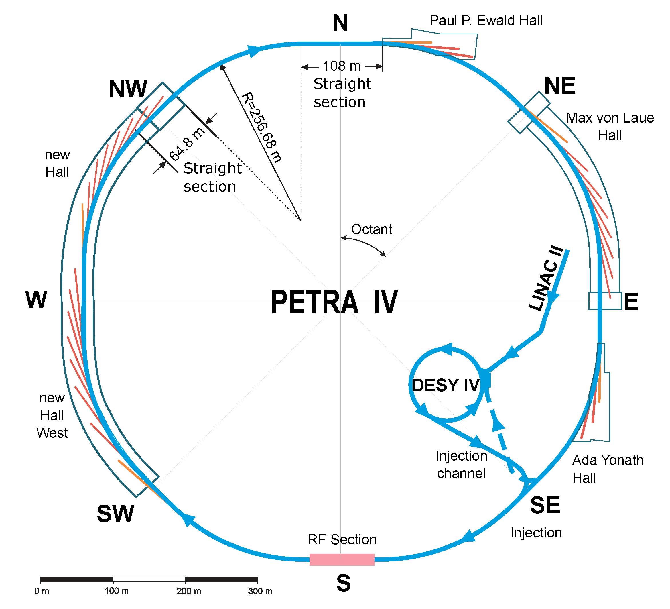
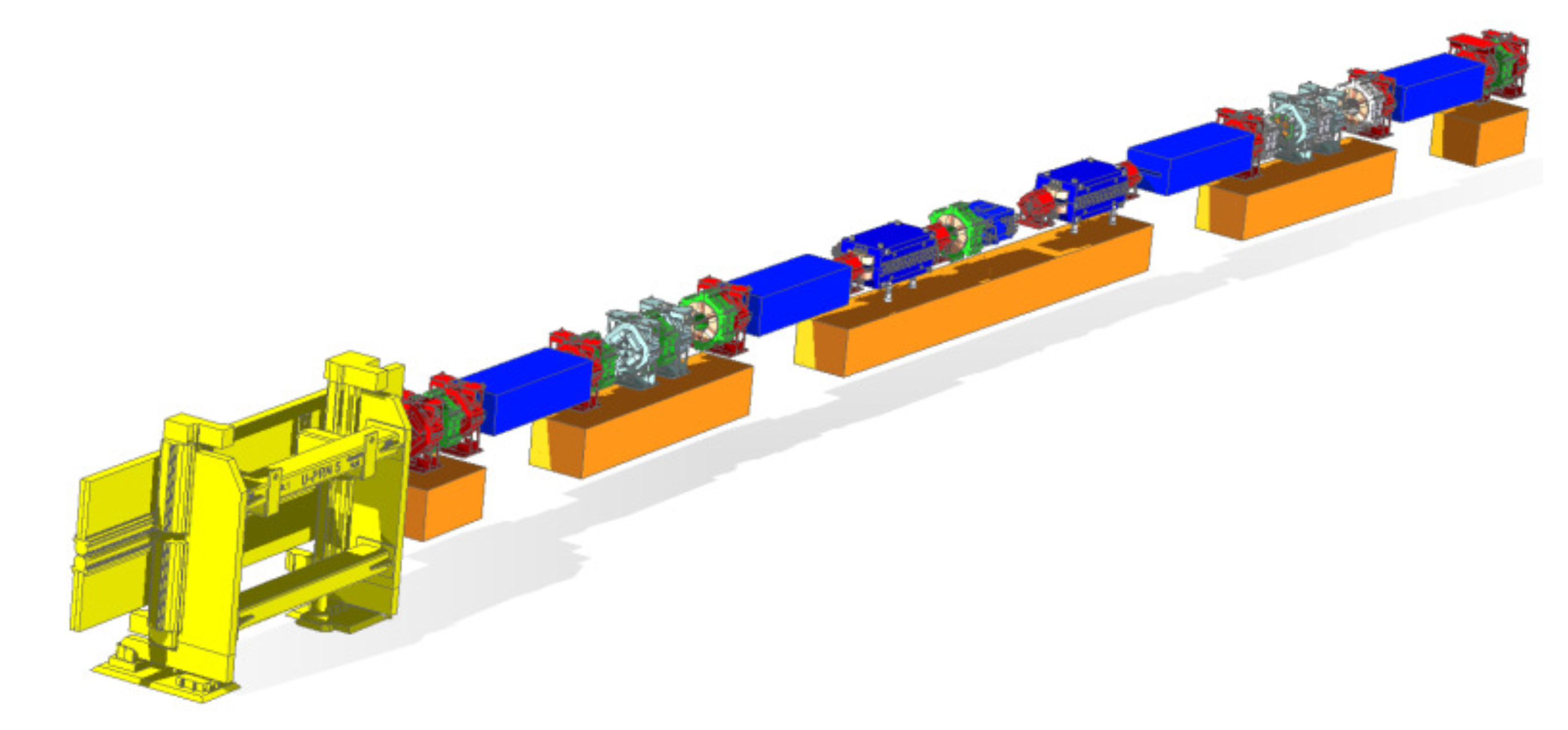
11]. This tunnel will also be used for the upgraded machine, which is why the dimensions of the girder structures studied here followed the PETRA III girder geometry. The layout of PETRA IV consists of eight arcs of 201.6 m length each and eight long sections, of which four are 108 m long and the remaining four 64.5 m (Figure 1). One arc is composed of eight identical cells, each of 26.2 m length. In each cell, five girders of 1 m, 3 m, and 6 m length are planned to support the magnets (Figure 2) [11]. The present study exemplarily focussed on the 3 m girder.
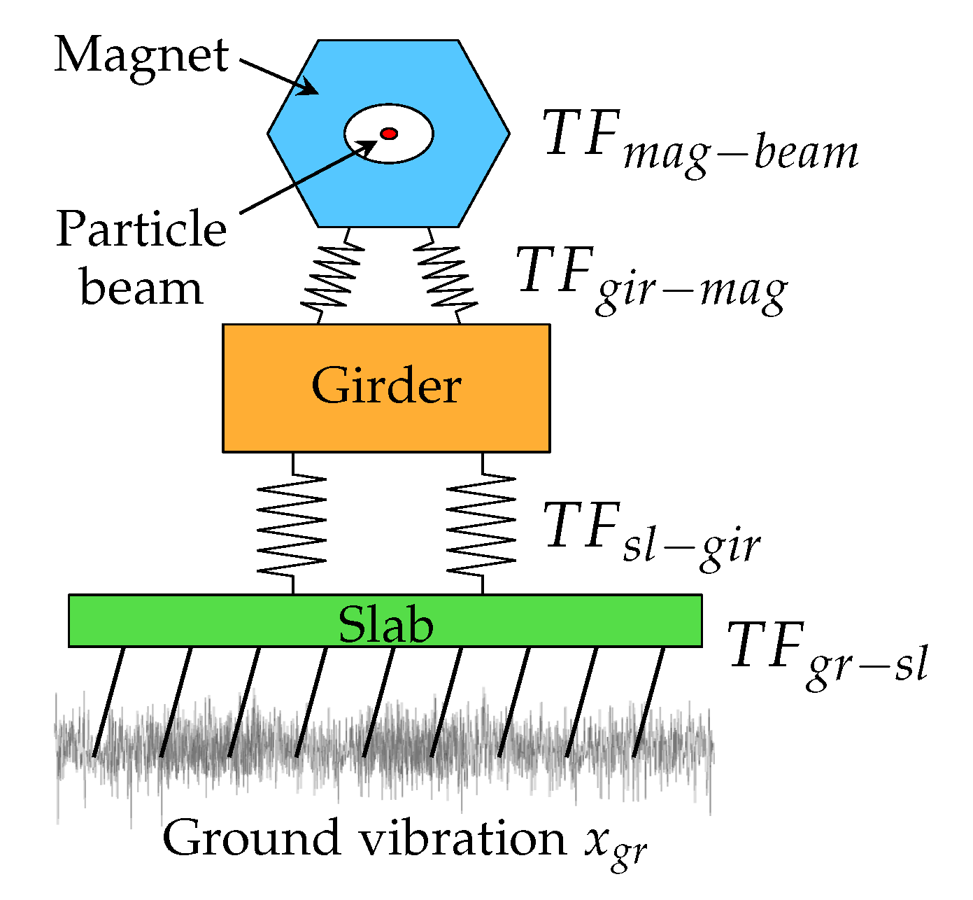
A high particle beam stability is essential to obtain a low-emittance and diffraction limited storage ring [14]. It depends, aside from the thermal issues, on the transfer function of the ground vibration to the particle beam, in which the girder plays a key role. This vibration transmission path is illustrated in Figure 3. Ground motions are inevitable. However, the vibrations reaching the particle beam Δ x b e a m should be less than 10% of the particle beam size σ x , b e a m to obtain the required particle beam stability and can be calculated as follows [14]:
Δ x b e a m = x g r · T F g r s l · T F s l g i r · T F g i r m a g · q d · T F m a g b e a m · q f o f b < 0.1 σ x , b e a m
Thus, Δ x b e a m depends on the ground vibrations x g r and on the transfer functions from the ground to the slab T F g r s l , from the slab to the girder T F s l g i r , from the girder to the magnet T F g i r m a g , and on the transfer function amplification due to the attice design T F m a g b e a m . The latter can be positively influenced by a fast orbit feedback factor q f o f b . In addition, in the case of low magnet–girder assembly eigenfrequencies, passive damping mechanisms (damping pads or materials) can reduce high vibration amplifications by a factor q d as applied to the APS (Argonne National Laboratory, Lemont, IL, USA) [15] or to the ESRF (Grenoble, France) [16].
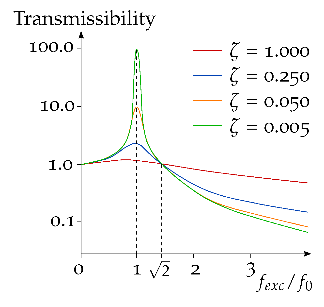
With regard to damping, Figure 4 shows the vibration transmissibility of a sinusoidal excitation depending on the ratio of the exciting frequency f e x c to the eigenfrequency f 0 for different damping ratios ζ [17]. Very soft supports lead to a f e x c / f 0 value larger than 2 , where the transmissibility is very low and the structure is isolated from the ground motion. Nevertheless, soft supports cannot be implemented in the accelerator machine because of the low tolerances between neighbouring girders. Damping mechanisms can be effectively applied to intermediate-stiffness supports that show f e x c / f 0 values around 1. However, if the structural eigenfrequency is significantly larger than the excitation frequency ( f e x c / f 0   < < 1), a high structural stiffness is present and damping mechanisms are not necessary because of the already low transmissibility [17]. Therefore, stiff magnet–girder assemblies with a high 1st eigenfrequency are inevitable to reach a high particle beam stability.
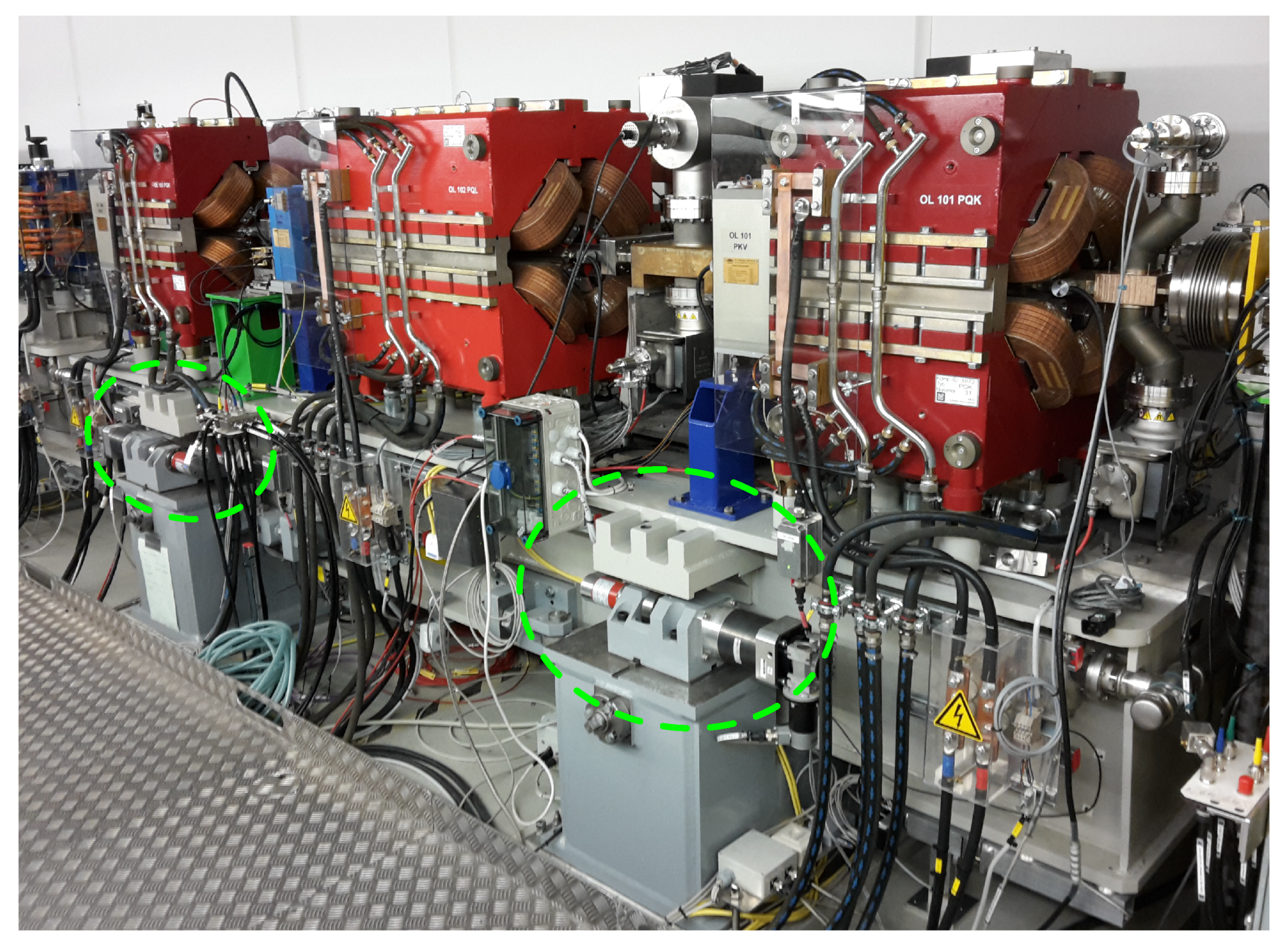
A published overview on magnet–girder assemblies of different accelerator machines worldwide showed that the 1st eigenfrequencies of the magnet–girder assemblies vary from about 10 Hz of the 3rd generation machines (ESRF, APS) and about 20 Hz for SPring-8 or SSRF (Shanghai, People’s Republic of China) to above 40 Hz for the new-generation light sources (SOLEIL, ESRF-EBS) [14]. Measurements of the currently installed PETRA III magnet–girder assembly revealed a 1st eigenfrequency of about 35 Hz and a 1st magnet mode at 25 Hz [18]. An equipped PETRA III girder installed in the PETRA tunnel is displayed in Figure 5.
Regarding the girder design and its boundary conditions, a compromise between stability (vibration, temperature) and adjustability (alignment) has to be made. On the one hand, a large number of girder support points increases the stiffness and thus the 1st eigenfrequency [19]. On the other hand, an over-determined system of more than three support points (assuming that at each support point, all six degrees of freedom are fixed) is difficult to align, especially considering the small tolerances. In addition, the thermal deformation of the girder tends to increase with a rising support point number [14]. While the vertical position of the girder is well defined by three points, more than three support points lead to an over-defined system and may hinder a symmetrical horizontal expansion. However, thermal issues are not addressed within this study. Regarding the girder alignment systems, motorised jacks and cam movers (e.g., applied to the PETRA III girder) have been used. In the latest magnet–girder assemblies, manual adjustments are more present, e.g., wedge jacks (APS, SSRF [14]) or precision levellers made by AirLoc AG (www.airloc.com, accessed on 31 August 2021) (e.g., SOLEIL [20] or ESRF-EBS [21]). Nevertheless, a support system allowing a girder adjustment at any time generally shows a lower stiffness than a non-adjustable support.
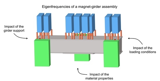
Summing up, there are many different specifications and demands that have to be taken into account to develop a new girder design. However, it is often not clearly understood how strongly the different specifications affect the stability of the magnet–girder assemblies. Therefore, different structural components and boundary conditions of a magnet–girder assembly were investigated in the present parametric study. The objective was to understand and quantify the impact of the varied parameters on the magnet–girder eigenfrequencies, before initiating the actual girder design process. Two different girder designs were taken into account. It was focused on the following parameters: the positioning and the mass of the magnets, the connection stiffness between the magnets and the girder and between the girder and the bases, the support point position of the girder, and the material properties of the girder and the bases. Based on the findings, the definition of the studied parameters can be improved to efficiently design magnet–girder assemblies with high eigenfrequencies required for a high particle beam stability.
The girder design and the boundary conditions followed the specifications defined for PETRA IV. It has to be noted, though, that the specifications considered here have been changed due to new insights of the PETRA IV project. Nevertheless, the findings of the parametric study are still relevant for future girder design processes in different synchrotron radiation facilities.

2. Materials and Methods

In the following, the finite element method (FEM) model of the studied magnet–girder assembly considering the specifications of the 3 m long PETRA IV girder is described. The parametric models were generated using the software Rhinoceros (version 6 SR10, Robert McNeel & Associates, Seattle, WA, USA) with its Plug-In Grasshopper (version 1.0.0007, Robert McNeel & Associates). All numerical models were solved using the solver OptiStruct (Altair Engineering Inc., Troy, MI, USA).
As the PETRA IV machine will be installed in the already available PETRA tunnel, the design space for the girders followed the dimensions of the currently installed PETRA III girders (cf.,
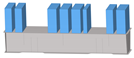
 Figure 5). 
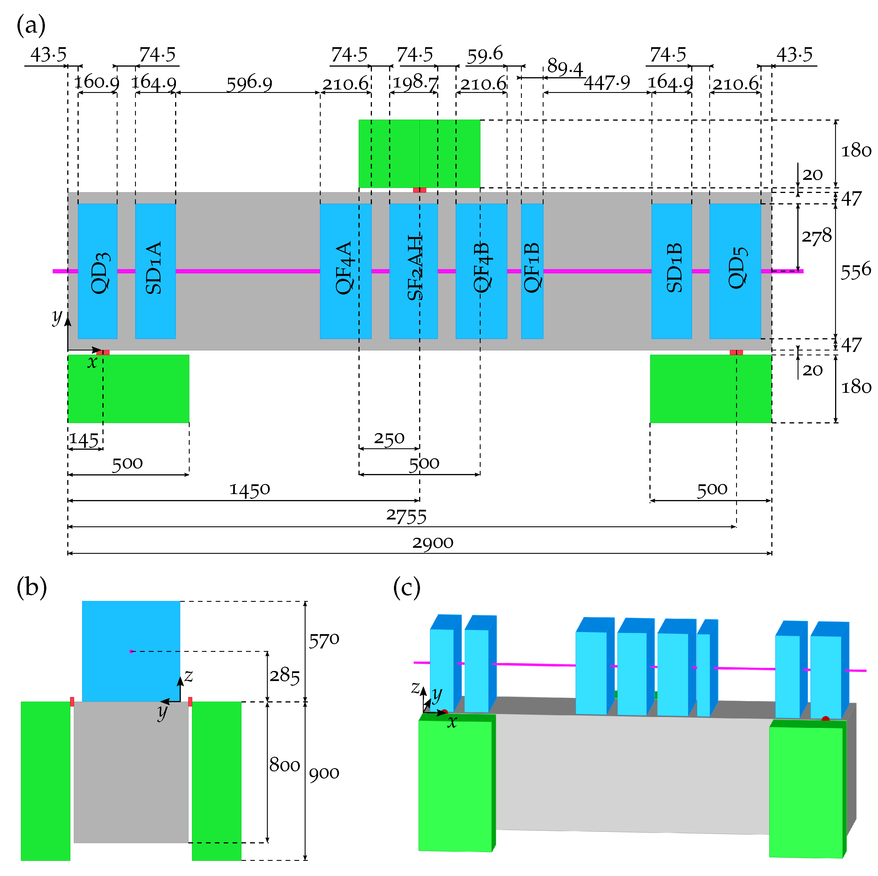
Figure 6 shows the girder design space, which was equipped with eight magnets and connected to three bases at three points with the x coordinates 0.05 l G , 0.50 l G , and 0.95 l G ( l G = 2900 mm, the girder length). The connection was realised using beam elements (CBEAM) with a diameter of 50 mm and a length of 20 mm, which were connected to the girder and the bases via rigid body elements (RBE3). The lower surface of the bases was considered as mounted.
For the girder, the bases, and the three connection beams, S235 was specified as a material characterised by a Young’s modulus E of 210,000 N mm 2 , a density ρ of 7.83 × 10 9 t mm 3 , and a Poisson’s ratio ν of 0.3.
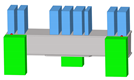
The girder was equipped with eight magnets varying in width (cf., Figure 6) and mass (Table 1), which were fixed to the upper girder surface. As the volume of each magnet V m a g was fixed, its targeted mass m m a g was obtained by defining an artificial density ρ m a g for each magnet. In addition, a mass factor q was defined as:
ρ m a g = q m m a g V m a g
Since the magnet masses listed in Table 1 were only first estimations, it was decided to set the factor q equal to 1.15 in order to conservatively assume a slightly higher magnet mass, as the heavy magnets have a strong impact on the overall eigenfrequencies. However, in the present studies, the factor q was varied to quantify the impact of the magnet mass on the magnet–girder eigenfrequencies.
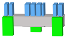
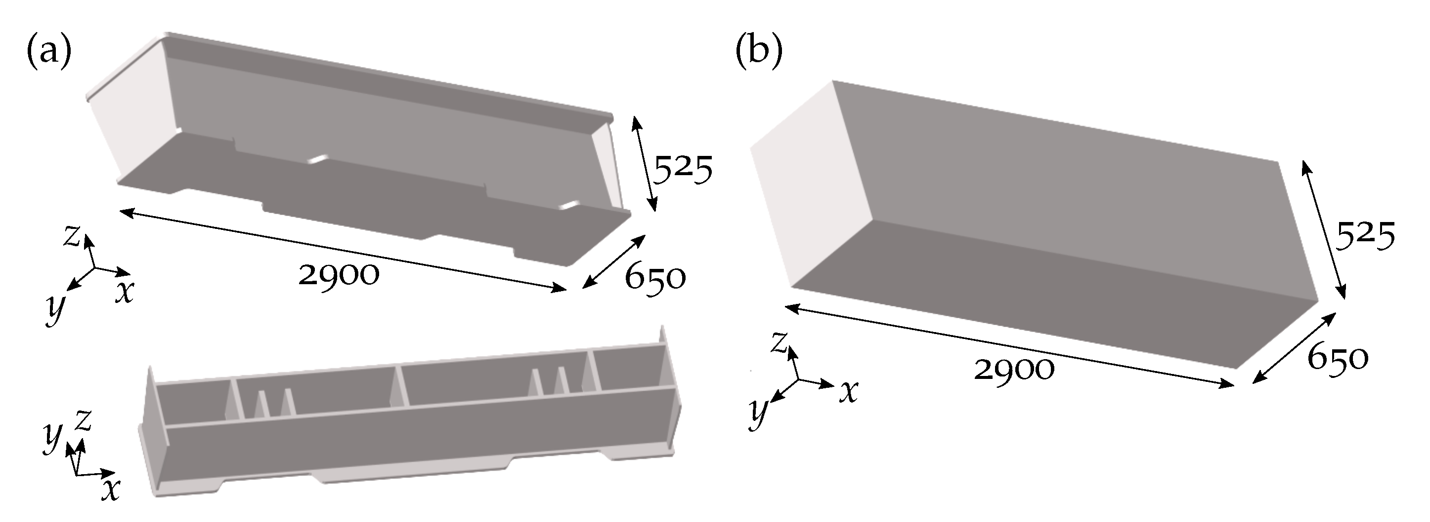
Hereinafter, the impact of different components and boundary conditions of the magnet–girder assembly on the eigenfrequencies was analysed. Two different girder geometries were taken into account to assess the influence of the girder design on the analysed parameters (Figure 7): (1) a hollow box girder that corresponded to the defined girder design space and possessed a wall thickness of 50 mm and (2) the PETRA III girder currently installed in the PETRA III machine, which has seven inner vertical ribs. The geometry of the 4200 mm long PETRA III girder was adapted to obtain a girder length of 2900 mm equal to the box girder length.
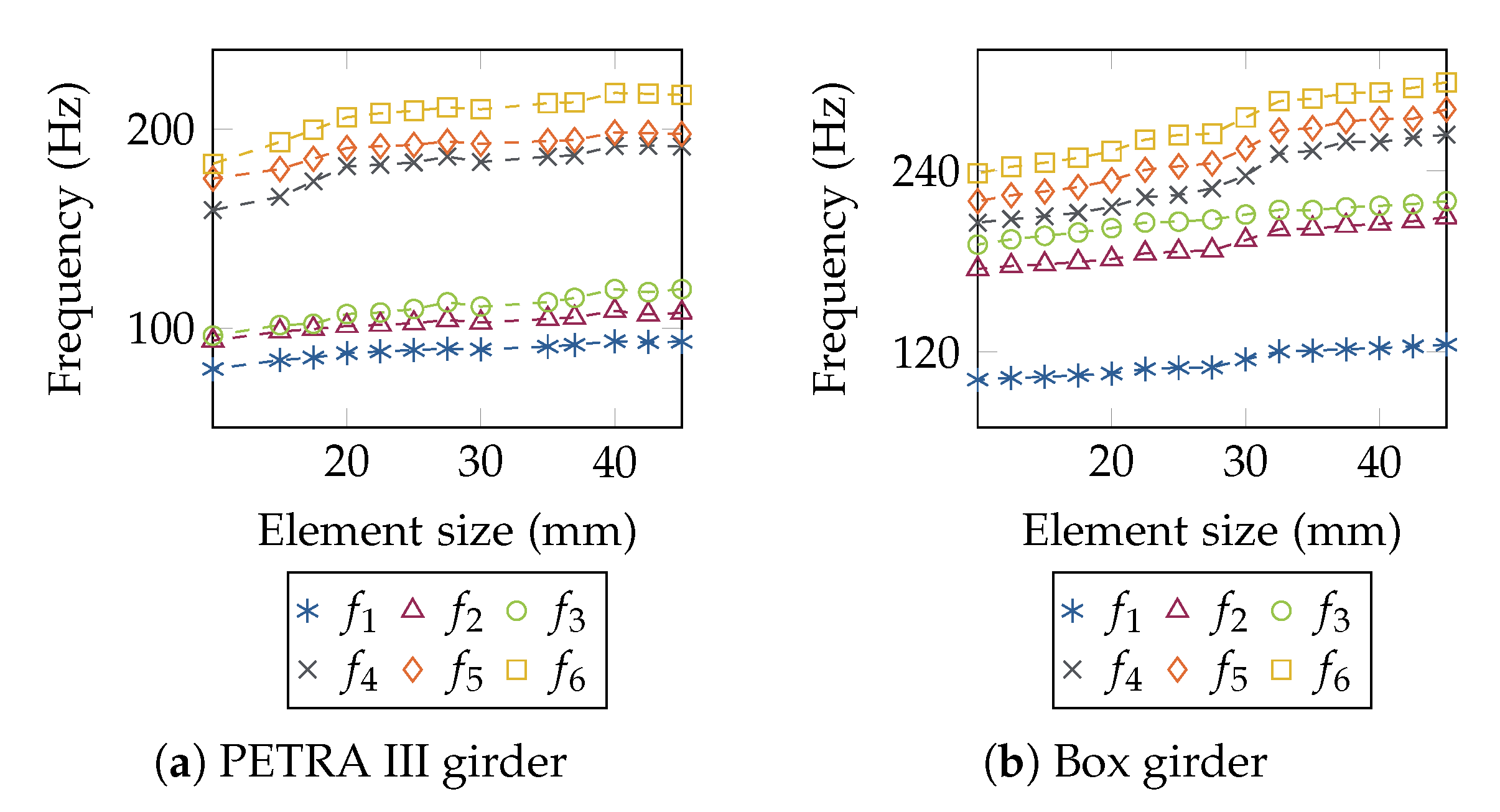
A mesh study of the FEM model varying the volume element (CTETRA) size from 10 mm to 45 mm in step sizes of 2.5 mm identified a sufficient element size applied to both the girder structures and the magnets. In this mesh study, only the girder structure equipped with magnets was considered. Thus, as the bases were neglected, a fixed support was defined at the three support point locations, i.e., all translations and rotations were inhibited. The element size, which showed result differences compared to the three previous element size steps of maximum 5%, was declared as sufficient.
During the parametric study, the following components and boundary conditions were altered and their impact on the first six eigenfrequencies of the magnet–girder assembly was investigated:
  • Magnet position height and connection;
  • Stiffness of the magnet–girder connection;
  • Magnet mass;
  • Girder support point position;
  • Stiffness of the girder support;
  • Material properties of the girder and the bases.
Table 2 lists the model components that were considered for each modal analysis, which required the definition of a modal load case.

2.1. Magnets

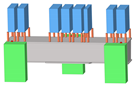
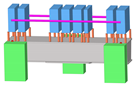
2.1.1. Magnet Position Height and Connection

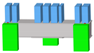
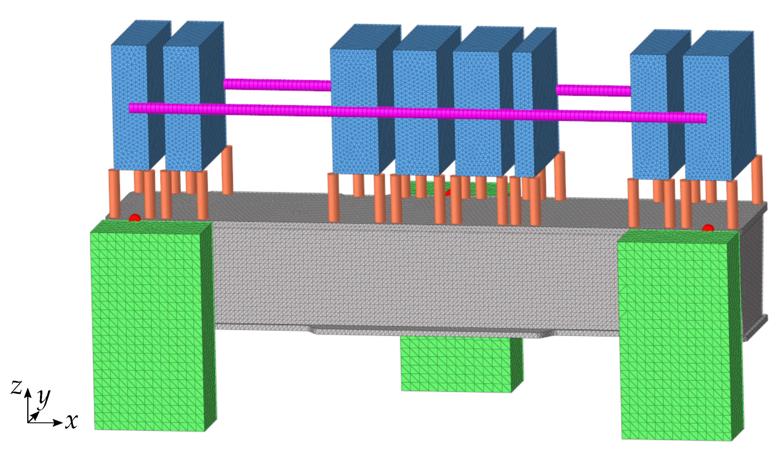
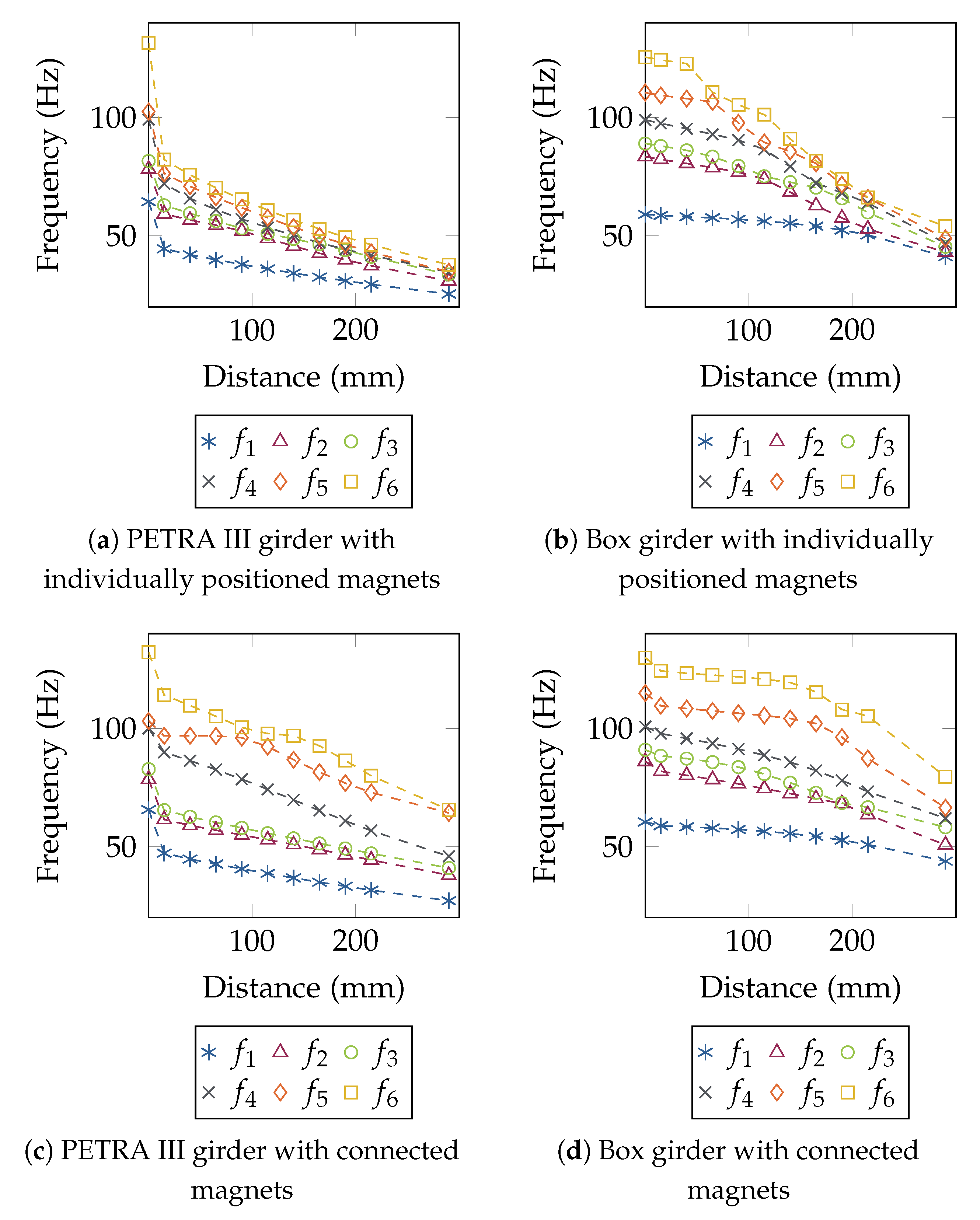
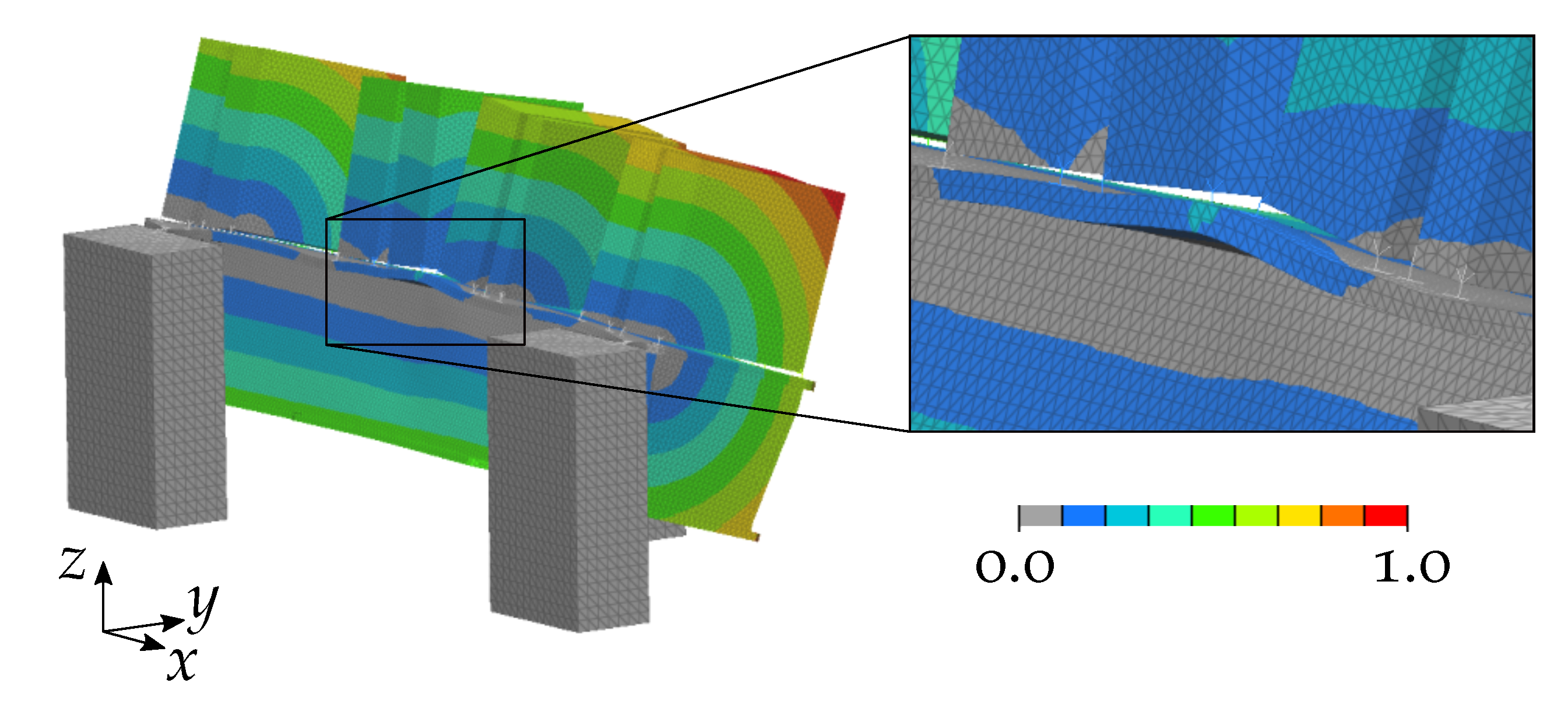
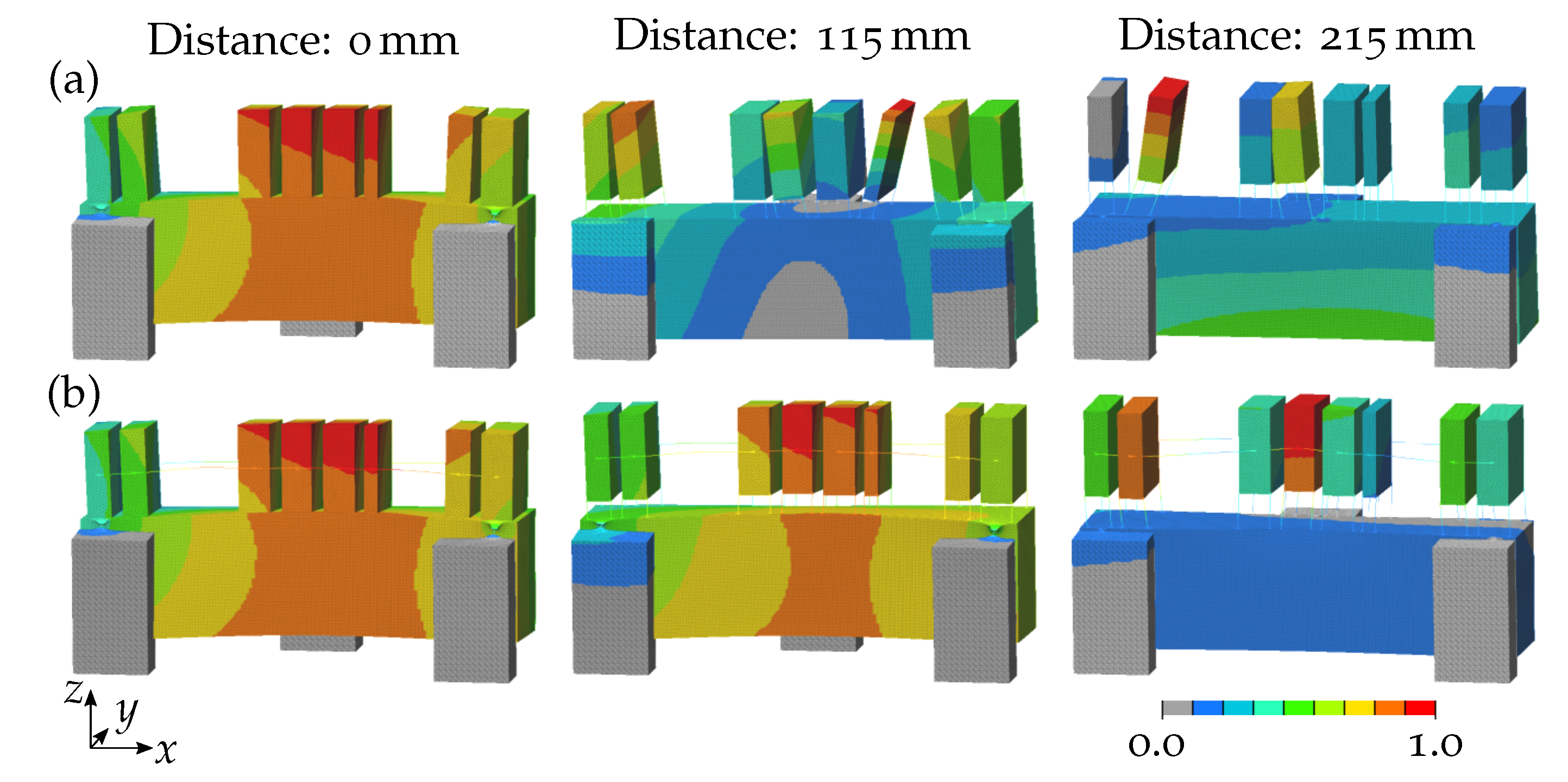
The distance between the lower magnet surface and the girder was altered from 15 mm to 215 mm with a step size of 25 mm. In addition, the distances 0 mm—magnets fixed to the girder—and 290 mm were analysed. Similar to the magnet–girder assembly currently installed in the PETRA III accelerator (cf., Figure 5), in which each magnet is connected to the girder via four screws embedded in resin, the magnets were positioned on the girder using four beams of 50 mm diameter each. The analyses were conducted for both the magnets positioned individually and the magnets connected to each other. The latter was realised using beams of 50 mm diameter that were fixed to the middle node of the front and back side of each magnet. All beams were connected to the magnets and the girder via RBE3. Figure 8 shows exemplarily the model assembly for the position height study of the connected magnets.

2.1.2. Stiffness of the Connection between Girder and Magnet

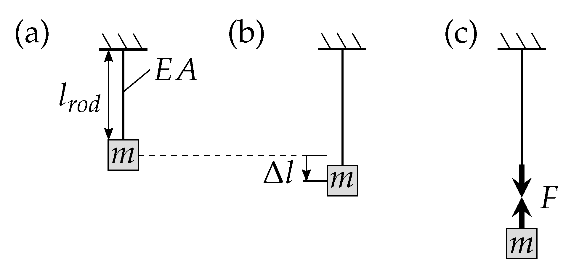
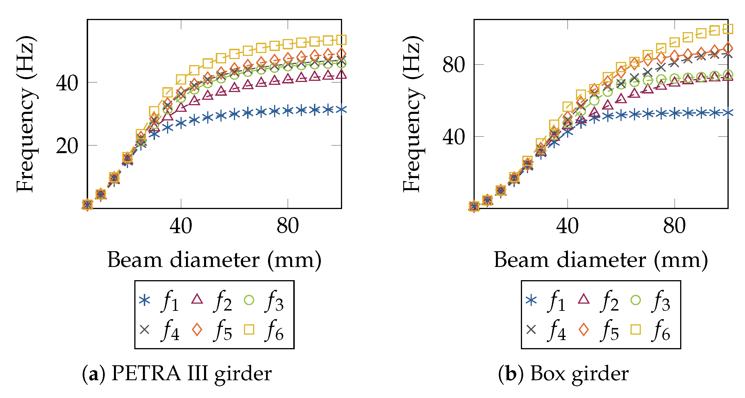
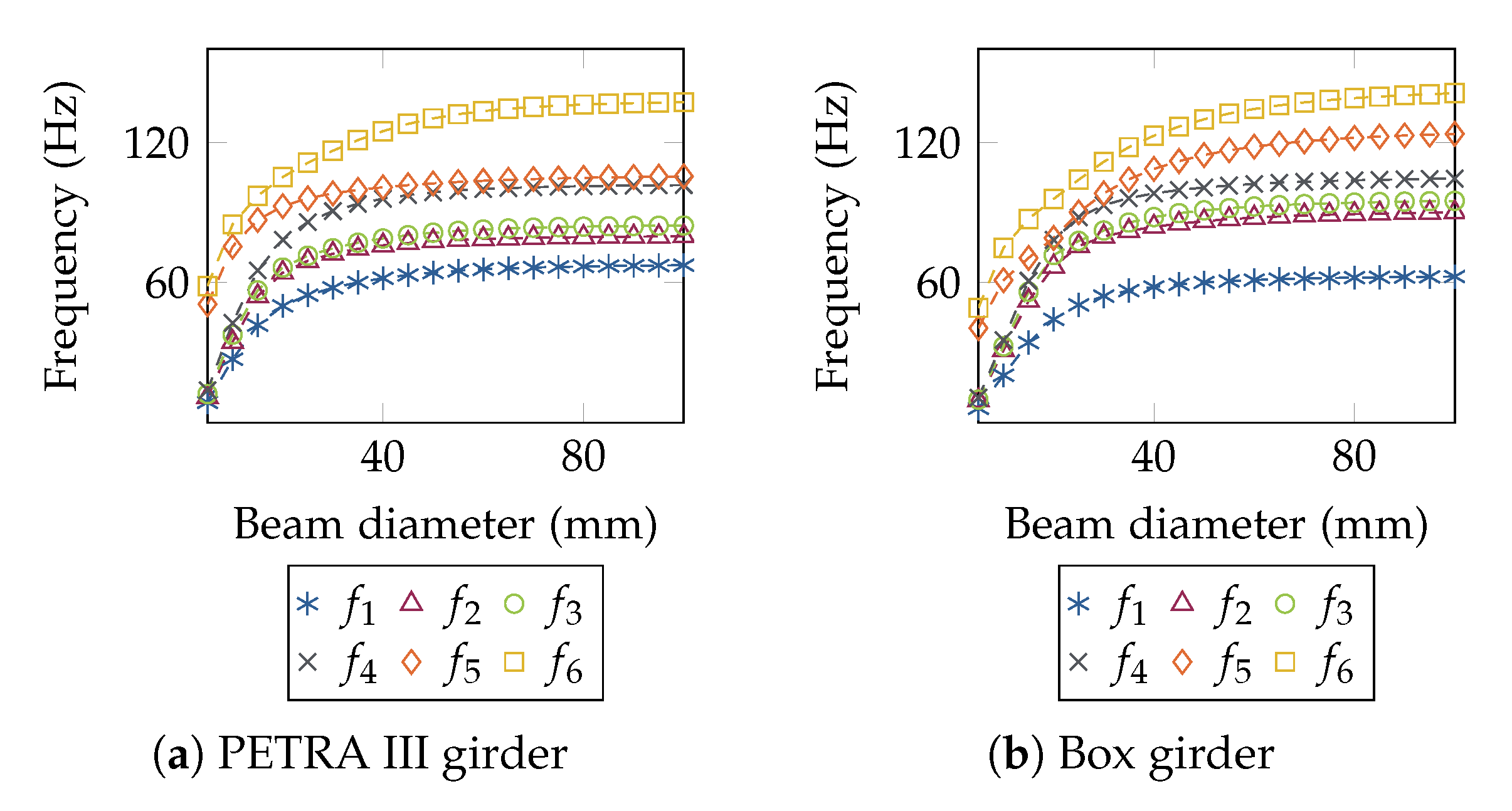
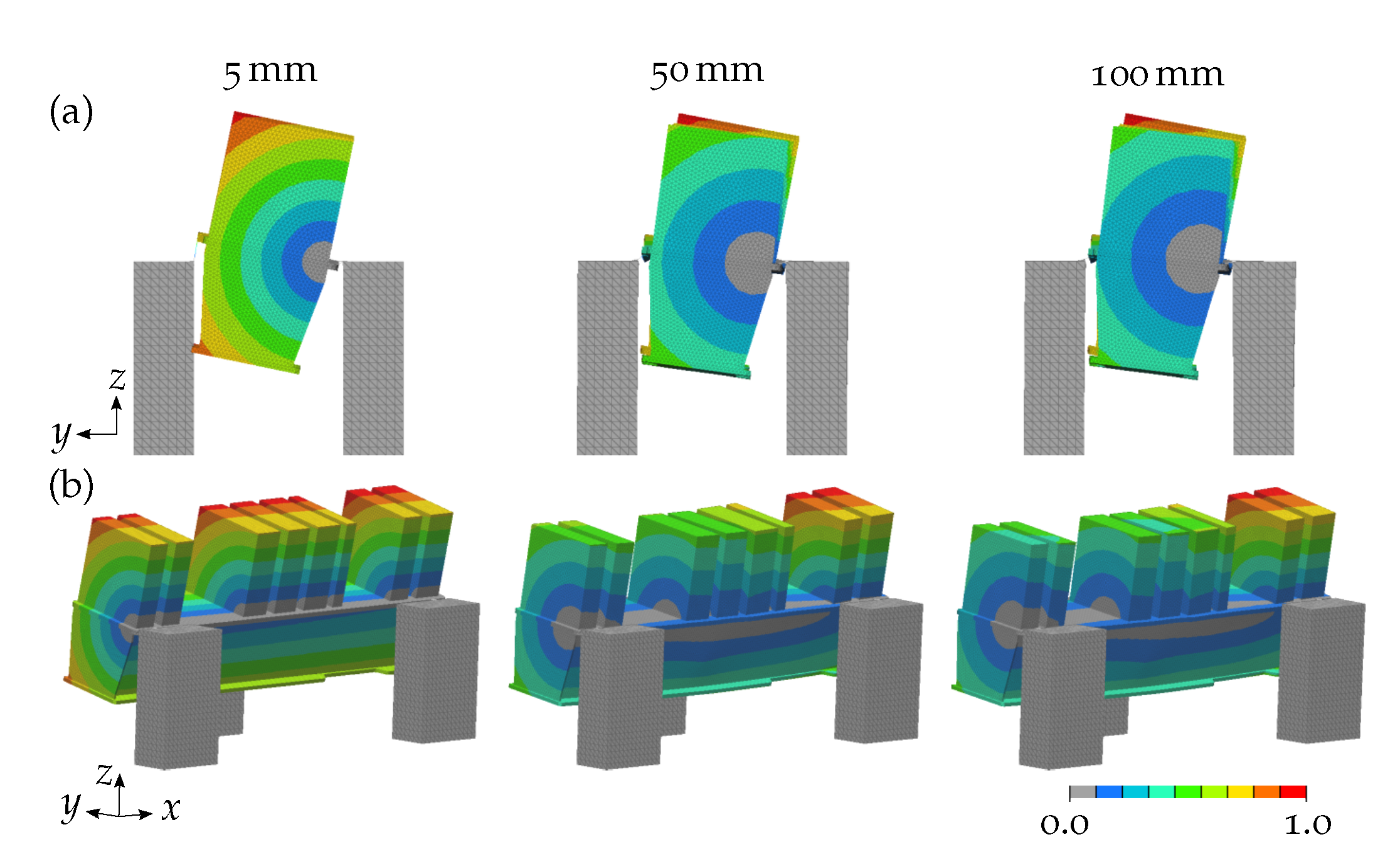
The diameter of the beams connecting the magnets to the girder was varied from 5 mm to 100 mm with a step size of 5 mm to investigate the impact of the connection stiffness on the magnet–girder assembly eigenfrequencies. A distance between magnets and girder of 215 mm was assumed following the magnet position height of the PETRA III girder.
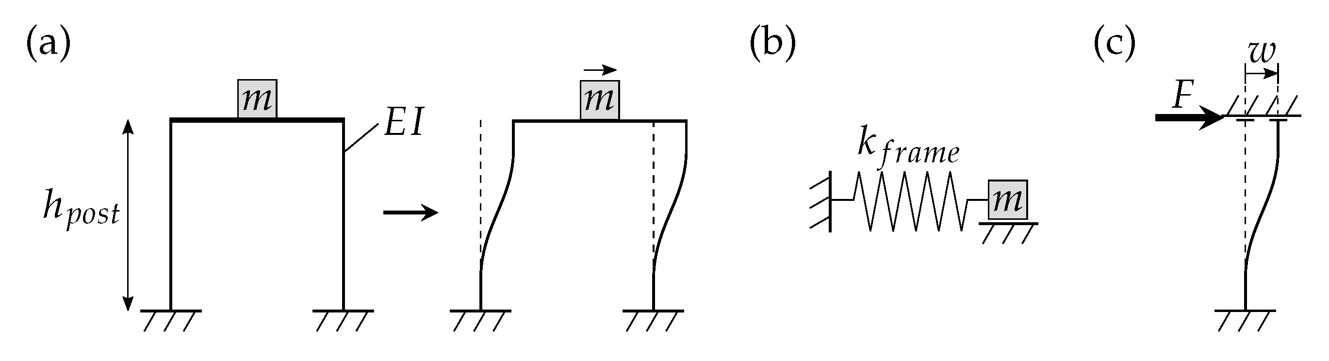
The fixation of a magnet on the girder can be abstracted as a frame composed of four elastic posts (height h p o s t , bending stiffness E I , with I denoting the second moment of inertia) and a rigid bar, on which a mass m is fixed that can only move horizontally (Figure 9). The stiffness k p o s t of one post depends on the applied force F and the deflection w [22]:
k p o s t = F w = 12 E I h p o s t 3 ; with : w = F h p o s t 3 12 E I
As the four posts are connected side-by-side (i.e., parallel), the resulting stiffness of the frame k f r a m e is the sum of the four single stiffnesses:
k f r a m e = 4 k p o s t
Thus, the 1st eigenfrequency of the frame f 1 , f r a m e is
f 1 , f r a m e = 1 2 π k f r a m e m = 1 2 π 48 E I m h p o s t 3
Based on these equations, the horizontal stiffness of the connection between girder and magnet was estimated using Equation (4), in which the stiffness is multiplied by 4, since one magnet is supported by four parallel beams. The lowest frequency of a horizontal rigid magnet mode was estimated using Equation (5) considering the mass of the heaviest magnet SF2AH (cf., Table 1). Regarding both equations, the magnets were abstracted as point masses on top of the beam neglecting the beam masses and the connection stiffness of the beam to the girder was assumed as infinitely stiff.
To estimate the vertical stiffness of the magnet support, the support was abstracted as four parallel massless rods, each of a length l r o d and an extensional stiffness E A provided with a mass m at its end. A is the cross section area of the rod. Figure 10 shows one of these rods. A movement of the mass leads to an equal extension Δ l of the rods. Thus, a restoring force acts on the mass. The total stiffness of the four rods is four times the rod stiffness k r o d defined as [22]:
k r o d = E A l r o d

2.1.3. Magnet Mass

To investigate the impact of the magnet mass on the magnet–girder assembly, the factor q (cf., Equation (2)) was varied from 0.10 to 2.05 with a step size of 0.15. The magnets were considered as fixed to the upper girder surface.

2.2. Girder Support

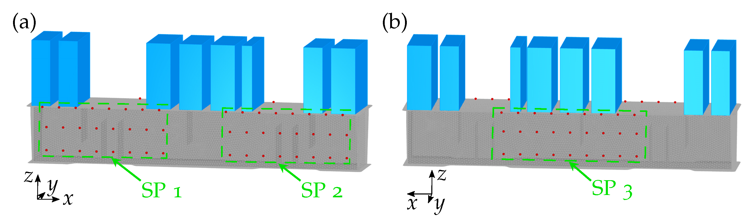
2.2.1. Support Point Position

In first published studies, the impact of the number and location of the girder support points on the eigenfrequencies were investigated [23]. The results showed a significant 1st eigenfrequency increase with a rising support point number. At each support point, all six degrees of freedom were fixed. Consequently, installing more than three support points would result in an over-determined system, which makes an accurate adjustment of the equipped girder in the tunnel difficult or even impossible. Thus, different positions of only three support points were analysed here.
Since both investigated girder geometries showed a thin wall compared to the girder length, a consideration of the girder as a shell body with the same element size that was obtained in the mesh study was possible. Due to the high number of analysed combinations of support point positions, a solid girder would have involved very time-consuming computational effort. In contrast, the magnets were still considered as solids to consider not only their masses, but also their moments of inertia.
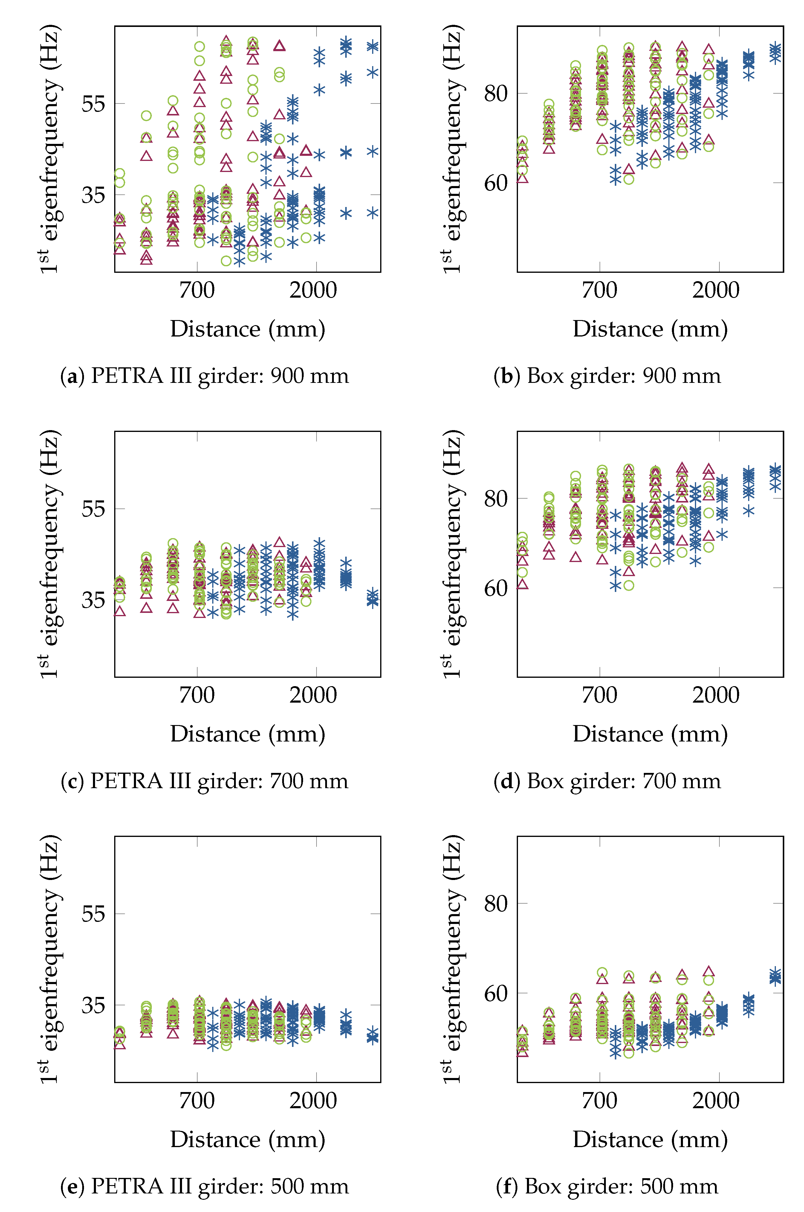
The x values of the support points were varied during the parametric study from 0.05 l G to 0.35 l G for point 1, from 0.65 l G to 0.95 l G for point 2, and from 0.3 l G to 0.7 l G for point 3 in step sizes of 0.1 l G , whereby l G symbolises the girder length. In addition, the study was conducted three times with different z values of the support points considering 900 mm, 700 mm, and 500 mm, which resulted in a total of 243 analysed support point position combinations.
Figure 11 shows all support points that were considered. The front and back wall of the PETRA III girder were positioned at y = 185.5 mm and y = 462.5 mm, i.e., closer to the girder centre (cf., Figure 7a). Consequently, the support points at heights of 500 mm and 700 mm were moved by 185.5 mm in the y direction (support points 1 and 2) and in the negative y direction (support point 3) to be defined on the girder wall.
The support point combination which led to the highest 1st eigenfrequency was chosen. Subsequently, the model was calculated with the girder considered as a solid body to estimate the deviation of the shell model from the volume model.

2.2.2. Stiffness of the Girder Support

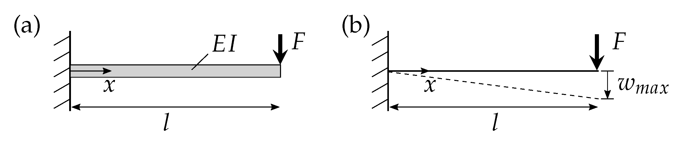
To study how the girder support stiffness affects the overall magnet–girder assembly eigenfrequencies, the diameter of the beams connecting girder and bases was varied from 5 mm to 100 mm in 5 mm steps.
Since only shear forces were relevant owing to the shortness of the beams, the shear stiffness k s h e a r of the connection between girder and bases was estimated based on a cantilever beam with a point load F (Figure 12). The maximum deflection w m a x at x = l is [24]:
w m a x = F l G A κ
As the stiffness depends on the force and the deflection (cf., Equation (3)), it is defined as:
k s h e a r = G A κ l
where G symbolises the shear modulus and κ is defined as 3/4 for the circular cross section presented here with the area A [25].

2.3. Material Properties

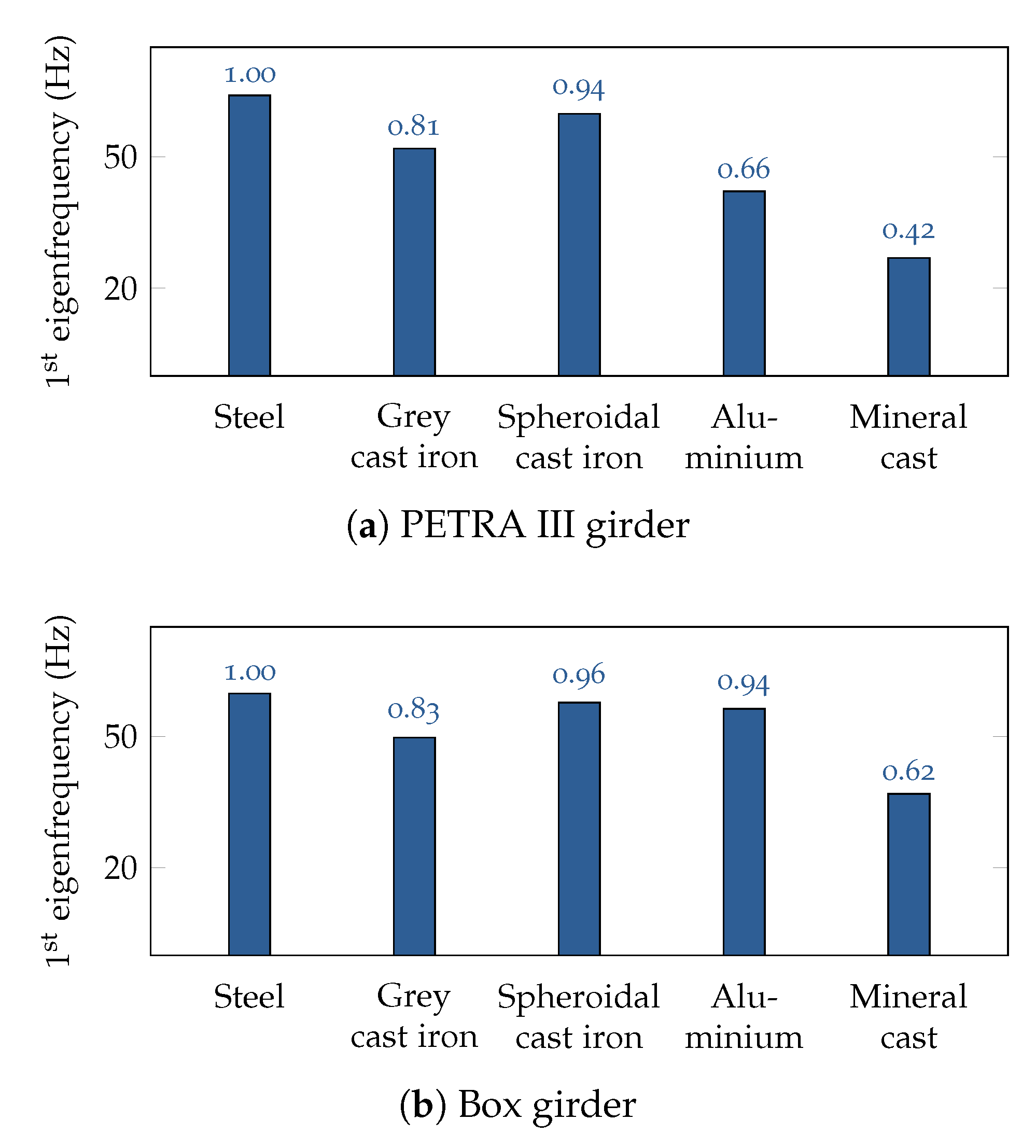
In the previous studies, S235 was considered as a material for the girder and the bases. Here, the impact of the material properties on the eigenfrequencies was analysed by considering the materials aluminium, grey cast iron, spheroidal cast iron, and mineral cast for the girder and the bases (Table 3). The results were compared to those obtained for the girder and bases made out of S235. Additionally, the ratio η defined as:
η = E / ρ
was considered as it can be seen as a parameter of how the Young’s modulus and the density, which are significant material properties, affect the eigenfrequency.

3. Results

This sub-chapter contains the parametric study results. The mesh study revealed a sufficient element size of 20 mm for both girder geometries considering the first six eigenfrequencies (Figure 13). The total number of elements was 76,600 for the PETRA III girder and 67,799 for the box girder.

3.1. Magnets

3.1.1. Magnet Position Height and Connection

Eigenfrequency decreases with increasing distance between the magnets and the girder were obtained for both girder geometries (Figure 14). Regarding the PETRA III girder with individually positioned magnets, a strong eigenfrequency decrease from 0 mm to 15 mm distance was followed by a slight continuous decrease of all eigenfrequencies with further increasing distance. Figure 15 shows the 1st mode shape for 15 mm distance between the magnets and the girder. Girder deformations at the connection to the magnet-beams occurred and indicated a lower connection stiffness, which did not appear at a distance of 0 mm, i.e., for the magnets fixed to the upper girder surface.
Apparently, including a magnet connection does not prevent the general trend of decreasing eigenfrequencies with increasing distance between girder and magnets. However, the eigenfrequencies decrease less strongly. The strongest impact of the magnet connection on the eigenfrequencies was obtained for large distances between girder and magnets and for the higher-order eigenfrequencies. In addition, the magnet connection led to higher eigenfrequency increases for the PETRA III girder than for the girder box.
Comparing exemplarily the 5th mode shape for the distances 0 mm, 115 mm, and 215 mm between the magnets and the box girder shows the impact of the magnet connection (Figure 16). With regard to the magnets fixed to the girder, the magnet connection did not alter the eigenfrequencies nor the mode shape. At a distance of 115 mm, the magnet connection prevented the local magnet modes and the overall mode shape was still similar to the 5th mode shape for the magnets fixed to the girder. However, at a high distance of 215 mm, the local magnet modes appeared despite the magnet connection that was also oscillating. Thus, the corresponding frequency decreased strongly.

3.1.2. Stiffness of the Connection between Girder and Magnet

For both girder geometries, all analysed eigenfrequencies rose with increasing connection stiffness between girder and magnets up to a certain stiffness value, after which the frequencies almost remained constant (Figure 17). Although the box girder eigenfrequencies showed higher values than the PETRA III girder and the trends of the curves also varied, the 1st eigenfrequency of both girder geometries remained almost constant from a beam cross section diameter of about 50 mm on. Higher-order eigenfrequencies reached constant values at higher beam diameters. Regarding the mode shapes, the 1st mode shape was characterised by local magnet modes for small beam diameters (Figure 18). As soon as the mode shape changed into a global tilting mode (beam cross section diameter of 30 mm for the PETRA III girder and 50 mm for the box girder), the corresponding 1st eigenfrequency remained almost constant. For a beam cross section diameter of 50 mm, the horizontal stiffness can be estimated as 311 N μ m 1 (Equation (4)) and the vertical stiffness as 7.7 × 10 3 N μ m 1 (Equation (6)).
Regarding the model based on a beam cross section diameter of 5 mm, the frequency of this mode shape characterised by a horizontal movement of the heaviest magnet SF2AH (cf., Table 1) can be compared to an analytically calculated eigenfrequency. Applying Equation (5) to the PETRA III girder model, the analytically obtained 1st eigenfrequency value of 5.7 Hz was higher than the numerical value of 1.1 Hz.

3.1.3. Magnet Mass

Figure 19 shows the impact of the mass factor q on the eigenfrequencies of both studied girder geometries. Additionally, the total magnet mass, which resulted from the factor q, is displayed on the upper horizontal axis of each plot. Almost all eigenfrequencies decreased with increasing magnet mass for both girder geometries. However, the 1st eigenfrequency of the box girder remained unaffected by the changing magnet mass. The corresponding mode shape showed a global rotation around an axis parallel and almost equal to the magnet axis (Figure 20). The rotation axis of the 1st mode shape of the PETRA III girder was farther away from the magnet axis, thus, the 1st eigenfrequency decreased with the rising magnet mass.

3.2. Girder Support

3.2.1. Support Point Position

The support point position strongly affected the 1st magnet–girder assembly eigenfrequency for both girder geometries (Figure 21). The higher the support points were located, the higher was the obtained 1st eigenfrequency. As exemplarily shown for the PETRA III girder in Figure 22, lowering the support points led to a lower rotation axis of the 1st rotational mode shape, which caused a 1st eigenfrequency decrease and larger vibration amplitudes of the magnets.
In addition, the 1st eigenfrequency generally increased with rising distance in x direction between the support points. Regarding the box girder, the 1st eigenfrequency reached its highest value for a maximum distance between the support points 1 and 2 and an equal distance of about 1300 mm between the support points 2 and 3 and the support points 1 and 3 (Table 4). For the PETRA III girder, the support point 1 position slightly differed to reach the maximum 1st eigenfrequency. Nevertheless, for both girder geometries, the highest eigenfrequencies were obtained defining the three support points to form a large (isosceles) triangle in the x y plane.
The obtained results based on a shell model were finally compared to those of a volume model. While the shell model resulted in a 1st eigenfrequency of 90 Hz for the box girder and 69 Hz for the PETRA III girder, the volume model revealed 1st eigenfrequencies of 98 Hz for the box girder and 76 Hz for the PETRA III girder. Thus, the results of both models coincided by 91% for the box girder and by 90% for the PETRA III girder.

3.2.2. Stiffness of the Girder Support

Similar to the results for the varying stiffness of the magnet–girder connection, an increasing girder support stiffness resulted in an eigenfrequency raise for both girder geometries until an almost constant value was reached for a specific beam cross section diameter of about 50 mm for the 1st eigenfrequency (Figure 23). For small beam diameters, the 1st mode shape was characterised by a tilting rigid body mode of the girder as shown exemplarily for the PETRA III girder in Figure 24. With increasing beam cross section diameter, the rigid body mode transformed into a girder twist mode. A similar behaviour of a rigid body mode being transformed into a girder deflection mode with increasing beam cross section diameter was also observed for the higher-order mode shapes.
For the analysed girder mode shapes, primarily shear forces were acting on the short support beams. Regarding a beam cross section diameter of 50 mm, the support stiffness for each support point can be estimated as 5.95 × 10 3 N μ m 1 considering Equation (8).

3.3. Material Properties

The eigenfrequency strongly depended on the material properties. Regarding the box girder, the 1st eigenfrequency differences compared to the S235 girder coincided well with the ratio η (cf., Table 3) indicating that a high η value led to a high 1st eigenfrequency (Figure 25). However, for the PETRA III girder, this relation only partly applied, as the normalised 1st eigenfrequency values of the aluminium and the mineral cast girder were lower than those of the box girder.

4. Discussion

The parametric study revealed a strong impact of all analysed components and boundary conditions on the eigenfrequencies of the magnet–girder assembly. Generally, the majority of the analysed relationships between the components and boundary conditions and the overall eigenfrequencies were independent of the studied girder geometries. In the following, the obtained results are discussed.

4.1. Magnets

The impact of the magnet position height and connection, the magnet connection stiffness, and the magnet mass on the magnet–girder assembly eigenfrequencies was studied. In the following, some comments on the obtained results are given.
Concerning the magnet position height and connection study, the strong eigenfrequency decrease from 0 mm to 15 mm height for the PETRA III girder resulted from the girder geometry. The beams connecting the magnets to the girder were fixed to the girder at the outer part of the upper surface that was not directly supported by the vertical girder walls, since those were slightly moved towards the girder centre (cf., Figure 7a). Consequently, already a slight ift of the magnets above the girder surface resulted in high stresses—and thus high deformations—in these areas. The connection stiffness of the magnets was reduced and so were the eigenfrequencies. This was not the case for the box girder, because the vertical girder walls were at the very ends of the upper girder surface, which is why the connection area to the beams was directly supported.
Regarding the study on the magnet connection stiffness, the analytical calculation of the magnet mode shape frequency was in the same order of the numerically obtained value, but still differed (5.7 Hz vs. 1.1 Hz). The differences can be explained by the simplification of the analytical model, in which the magnet volume was not considered. Consequently, the centre of mass was assumed to be lower than that in the numerical model and the magnet mass inertia was also neglected. In addition, the girder had a certain stiffness, which was abstracted to be infinite in the analytical model. However, since both obtained frequency values were still in the same order, the numerical value can be seen as plausible.
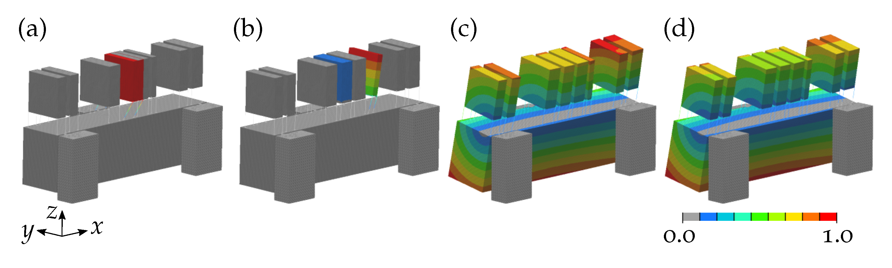
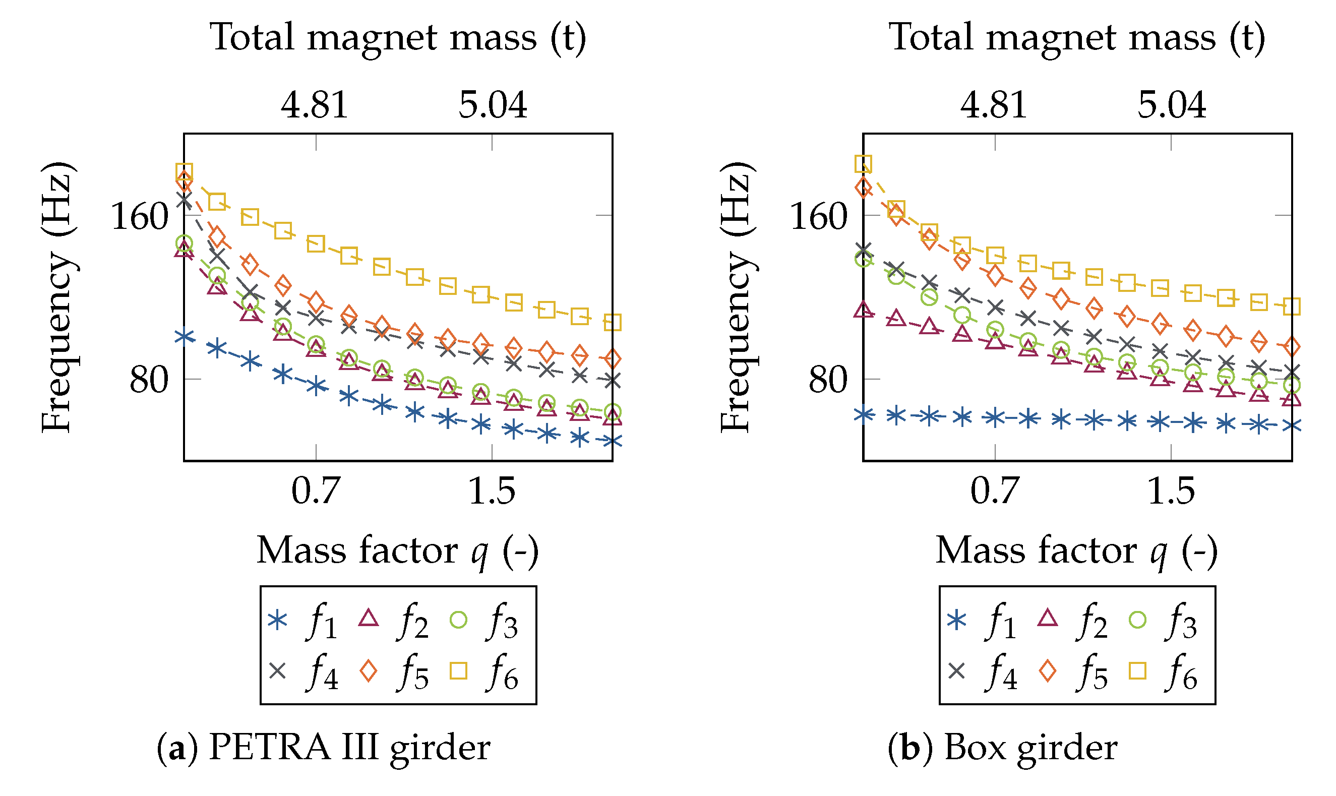
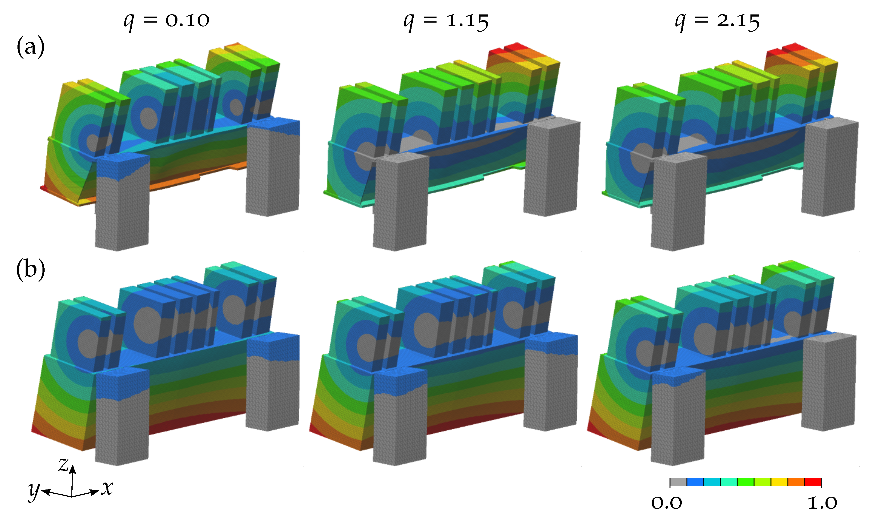
The analyses of the magnet mass impact on the eigenfrequencies showed that the 1st box girder eigenfrequency did not vary with increasing magnet mass. This highlights that the girder eigenfrequency can be independent of the magnet mass, if the corresponding mode shape is characterised by a global rotation around an axis as close as possible to the magnet axis (i.e., to the particle beam).
In summary, the study indicated that the following aspects positively influence (i.e., increase) the magnet–girder assembly eigenfrequencies:
  • A low position of the magnets (i.e., as close as possible to the upper girder surface);
  • Connecting the magnets to each other;
  • A high stiffness of the connection between girder and magnets (i.e., a high stiffness of the magnet alignment system);
  • A low magnet mass;
  • Mode shapes that show a global rotation around an axis close to the particle beam.
The currently installed PETRA III girder is equipped with magnets positioned high above the upper girder surface using an alignment system for each magnet (cf., Figure 5), which leads to a decrease of the overall eigenfrequencies as shown in the parametric study. For PETRA IV, a different magnet alignment system is planned to increase the magnet support stiffness and to avoid low frequency magnet eigenmodes.
Recently, the alignment system EASy has been invented at DESY [26]. The EASy type A3 is discussed to be placed between the PETRA IV magnets and the girder. The alignment component is 234 mm high [26], which implies a distance between magnets and girder similar to the maximum value of 215 mm that was analysed in the present parametric study. First experiments on the EASy A3 revealed a minimum horizontal stiffness of 50 N μ m 1 and a vertical stiffness of slightly more than 1.0 × 10 3 N μ m 1 [27]. In contrast, the parametric study model, in which each magnet was connected to the girder using four beams with a cross section diameter of 50 mm, showed a magnet support stiffness of 311 N μ m 1 horizontally and 7.7 × 10 3 N μ m 1 vertically. These values are significantly higher than the measured stiffness for the EASy A3. Moreover, considering the analytical calculations based on Equation (6), a vertical stiffness of 1000 N μ m 1 would correspond to a beam diameter of about 18.1 mm. Following the relation between the beam cross section diameter and the 1st eigenfrequency displayed in Figure 17, a cross section diameter of 18.1 mm would result in a 1st eigenfrequency of the magnet–girder assembly of about 13 Hz. However, it shall be noted again that this calculation is based on a simplified analytical model, which is why the estimated eigenfrequency value, as well as the calculated stiffness value of the magnet support have to be interpreted with caution. In further studies, the connection stiffness of the magnets positioned on the girder should be measured to ensure that reliable values are discussed.
At the MAX IV synchrotron radiation facility aboratory, all magnets positioned on one girder are linked in one large box to avoid low frequency magnet bending modes [28]. The parametric study results also indicated that connecting the magnets raises the overall eigefrequencies, because rigid magnet modes at low frequencies are prevented. However, the implementation of a magnet connection is probably not possible for PETRA IV, because an easy and individual adjustment of all magnet installed in the tunnel is required. Consequently, the low frequency magnet bending modes have to be avoided by a very high stiffness of the alignment system.

4.2. Girder Support

The study of the girder support position and stiffness indicated that the following aspects increase the eigenfrequencies:
  • A high position of the support points;
  • A horizontal support point positioning in form of a large (isosceles) triangle;
  • A high girder support stiffness.
In different synchrotron machines worldwide, girders are fixed by using more than three support points (e.g., SOLEIL [20] or NSLS-II [29]). However, as already mentioned in Section 2.2.1, more than three support points result in an over-determined system, which makes the girder alignment in the tunnel almost impossible. In addition, due to a possible ground settlement during the accelerator operation for many years, a girder alignment might be necessary. Therefore, only three support points were considered here.
Based on the results, the support points should be positioned in a large triangle involving an increased support span to obtain a higher stability and thus higher eigenfrequencies, which was also mentioned in a study on the APS-U girder design [30]. Moreover, the support points should be placed as high as possible, which was also obtained in previous studies [19,23]. low support point locations would decrease the eigenfrequencies and increase the vibration amplitudes of the magnets in the case of resonance, which should be avoided to guarantee a high functionality of the particle accelerator.
In addition to the support point position, a high stiffness of the girder support system is essential, which is why an appropriate girder alignment system should be chosen. Apparently, wedge jacks and AirLoc AG’s precision levellers allow a high girder support stiffness, because they have been used in the latest magnet–girder assemblies (cf., Section 1). Regarding the APS-U girder, the implementation of stiff lateral pushers also rose the eigenfrequencies significantly [31]. Once a girder is aligned, an additional clamping system can further increase the support stiffness and the magnet–girder assembly eigenfrequencies, as applied to the SOLEIL girder [20,32].
It is also important to note that a high stiffness of the bases, on which the girder is positioned, is necessary to obtain high eigenfrequencies. As shown in previous studies, a low base stiffness can strongly reduce eigenfrequencies [23]. For this reason, the here considered bases were heavy and stable solid blocks, which can also be utilised for PETRA IV.

4.3. Material Properties

The material properties strongly influence the eigenfrequencies of the magnet–girder assembly. As eigenfrequencies are known to be proportional to the Young’s modulus and anti-proportional to the mass [22], the observed high dependency of the 1st eigenfrequency on the ratio η was expectable. However, this effect seems to only fully apply to the simple box girder. The PETRA IV girder shows a more complex geometry involving an irregular material (mass) distribution. Consequently, not only the ratio η , but also the irregular mass distribution has a significant effect on the eigenfrequencies. Thus, it can be concluded that the consideration of the ratio η is very useful as a first approach to evaluate the effectiveness of a girder (bases) material, especially for simple girder structures, before further detailed analyses shall be carried out.
Aside from the ratio η , further material properties have to be taken into account for the decision on the girder/bases material: Girders placed next to an undulator should have a very low magnetisability to avoid an undesired impact on the undulator magnetic field. Furthermore, the temperature stability and corrodibility of a girder and bases material are important characteristics, because variations in the tunnel air temperature and humidity can cause corrosion and structural deformations. Although the PETRA IV tunnel temperature will be stabilised to ±1 K [11], an outage is always possible, which is why the girder (and bases) material should show a high temperature stability. However, the temperature stability will not be analysed in this work.
Girders of different synchrotron facilities are made of materials such as carbon steel (ESRF-EBS [21]) or ductile cast iron (APS-U [31]). As the PETRA IV girder or bases might be made of grey or spheroidal cast iron, both materials were studied here. They showed a ratio η similar to S235 (cf., Table 3) and the small deviations in the ratio correlate with the 1st eigenfrequency deviations. Consequently, based on the eigenfrequency results using a steel girder, the eigenfrequency values for a cast iron girder can be estimated.

4.4. Outlook

In the following, different issues that should be investigated in further studies are mentioned.
As ground vibrations decrease with increasing frequency [33], one of the common girder design objectives is to maximise the 1st eigenfrequency, which is why this study focused on this issue. However, in some cases, specific frequency values are precarious, e.g., due to the vibration of other components of the synchrotron radiation facility. Thus, the magnet–girder eigenfrequencies have to be shifted out of the range of these exciting frequencies in order to avoid resonance phenomena. In continuative studies, this issue could be addressed, e.g., by more explicitly investigating the sensitivity of the 1st magnet–girder eigenfrequency to varying boundary conditions or components.
In the majority of the modern synchrotron radiation facilities, the girders are not fixed at each support point. Instead, there are different girder support (alignment) systems that have more than three support points, but do not imply an over-constrained system, e.g., by using cam movers [34]. Thus, an easy alignment is still possible. As there are different girder support systems utilised in synchrotron radiation facilities worldwide, a detailed investigation of the impact of the different support systems on the magnet–girder eigenfrequencies would perfectly complement the present study.
Another issue that could be analysed in further studies is the impact of horizontal movements (parallel to the particle beam) of the magnets on the magnet–girder eigenfrequencies. Oftentimes, the girder design process starts, although the magnet attice is not yet fully defined. Therefore, studying the sensitivity of the eigenfrequencies to lateral magnet movements might be interesting for many engineers working on girder designs.

5. Conclusions

The impact of different boundary conditions and material properties on a magnet–girder assembly was investigated exemplarily focussing on two 3 m long PETRA IV girders. The loading conditions (magnet position height and stiffness, and the magnet mass), the girder support (location of the support points and the support stiffness), and the material properties of the girder and bases strongly influence the eigenfrequencies of the magnet–girder assembly.
Based on the findings, the following suggestions can be stated to generally raise the eigenfrequencies of a magnet–girder assembly necessary for a high particle beam stability:
  • Loading condition: The magnets should be as light as possible and positioned closely to the upper girder surface. In the case of a high magnet position, a high connection stiffness between the magnets and the girder, a stiff connection of the magnets among each other, and a 1st mode shape showing a global rotation around an axis close to the particle beam favour the raise of the magnet–girder eigenfrequencies.
  • Girder support: locating the support points as high as possible (i.e., close to the upper girder surface) and in the shape of a large (isosceles) triangle as well as a high girder support stiffness lead to high magnet–girder eigenfrequencies.
  • Material properties: While the ratio η scales with the 1st eigenfrequency for simple girder geometries, it is not necesarily the case for more complex girder structures. Nevertheless, considering the ratio η is very useful as a first approach to compare the effectiveness of different girder materials.

Funding

This research is part of the project ‘Good Vibrations’ funded in equal parts by the Alfred Wegener Institute Helmholtz Centre of Polar and Marine Research (AWI) and the German Electron Synchrotron, a Research Centre of the Helmholtz Association (DESY).

Institutional Review Board Statement

Not applicable.

Informed Consent Statement

Not applicable.

Data Availability Statement

Not applicable.

Conflicts of Interest

The author declares no conflict of interest.

References

  1. Schroer, C.G.; Agapov, I.; Brefeld, W.; Brinkmann, R.; Chae, Y.-C.; Chao, H.-C.; Eriksson, M.; Keil, J.; Nuel Gavaldà, X.; Röhlsberger, R.; et al. PETRA IV: The ultralow-emittance source project at DESY. J. Synchrotron Radiat. 2018, 25, 1277–1290. [Google Scholar] [CrossRef] [PubMed] [Green Version]
  2. Gisriel, C.; Coe, J.; Letrun, R.; Yefanov, O.M.; Luna-Chavez, C.; Stander, N.E.; Lisova, S.; Mariani, V.; Kuhn, M.; Aplin, S.; et al. Membrane protein megahertz crystallography at the European XFEL. Nat. Commun. 2019, 10, 1–11. [Google Scholar] [CrossRef] [PubMed] [Green Version]
  3. Douangamath, A.; Fearon, D.; Gehrtz, P.; Krojer, T.; Lukacik, P.; Owen, C.D.; Resnick, E.; Strain-Damerell, C.; Aimon, A.; Ábrányi-Balogh, P.; et al. Crystallographic and electrophilic fragment screening of the SARS-CoV-2 main protease. Nat. Commun. 2020, 11, 1277–1290. [Google Scholar] [CrossRef] [PubMed]
  4. Van Veelen, A.; Koebernick, N.; Scotson, C.S.; McKay-Fletcher, D.; Huthwelker, T.; Borca, C.N.; Mosselmans, J.F.W.; Roose, T. Root-induced soil deformation influences Fe, S and P: Rhizosphere chemistry investigated using synchrotron XRF and XANES. New Phytol. 2020, 225, 1476–1490. [Google Scholar] [CrossRef] [PubMed]
  5. Wang, Y.; Jia, S.; Wei, M.; Peng, L.; Wu, Y.; Liu, X. Research progress on solidification structure of alloys by synchrotron X-ray radiography: A review. J. Magnes. Alloys 2020, 8, 396–413. [Google Scholar] [CrossRef]
  6. Sun, T.; Tan, W.; Chen, L.; Rollett, A. In situ/operando synchrotron x-ray studies of metal additive manufacturing. MRS Bull. 2020, 45, 927–933. [Google Scholar] [CrossRef]
  7. Willmott, P. An Introduction to Synchrotron Radiation. Techniques and Applications, 2nd ed.; John Wiley & Sons, Inc.: Hoboken, NJ, USA, 2019. [Google Scholar] [CrossRef]
  8. Hastings, J.B.; Rivkin, L.; Aeppli, G. Present and Future Accelerator-Based X-ray Sources: A Perspective. Rev. Accel. Sci. Technol. 2019, 10, 33–48. [Google Scholar] [CrossRef]
  9. Agapov, I.; Bacher, R.; Bieler, M.; Bospflug, R.; Brinkmann, R.; Chae, Y.-C.; Chao, H.-C.; Duhme, H.T.; Ebert, M.; Eckoldt, H.-J.; et al. Status of the PETRA IV project. 10th International Particle Accelerator Conference (IPAC’19), Melbourne, Australia; Zimmermann, F., Bogacz, A., Assmann, R., Bai, M., Bambade, P., Byrd, J., Garnet, R., Fischer, W., Hsu, K., Kang, H., Eds.; JACoW Publishing: Geneva, Switzerland, 2019. [Google Scholar] [CrossRef]
  10. Röhlsberger, R.; Schroer, C.G.; Wanzenberg, R.; Klumpp, S.; Wurth, W. Light source upgrades at DESY: PETRA IV and FLASH2020+. Synchrotron Radiat. News 2019, 32, 27–31. [Google Scholar] [CrossRef]
  11. Schroer, C.G.; Röhlsberger, R.; Weckert, E.; Wanzenberg, R.; Agapov, I.; Brinkmann, R.; Leemans, W. PETRA IV. Upgrade of PETRA III to the Ultimate 3D X-ray Microscope, Conceptual Design Resport, German Electron Synchrotron (DESY). 2019. Available online: https://bib-pubdb1.desy.de/record/426140/files/DESY-PETRAIV-Conceptual-Design-Report.pdf (accessed on 31 August 2021).
  12. Wanzenberg, R.; Agapov, I.; Brefeld, W.; Brinkmann, R.; Chae, Y.-C.; Chao, H.-C.; Keil, J.; Gavaldà, X.N.; Röhlsberger, R.; Schroer, C.G.; et al. Design status of the ultra-low emittance synchrotron facility PETRA IV. AIP Conf. Proc. 2019, 2054, 030002. [Google Scholar] [CrossRef] [Green Version]
  13. Andresen, S.; Körfer, M.; Krause, B.; Meyners, N.; Petrov, A.; Thede, M. Research and Developement PETRA IV. Magnets, Girders and Vibrations, Poster at the 6th International Diffraction Limited Storage Ring (DLSR) Workshop. 2018. Available online: https://epic.awi.de/id/eprint/48567/1/DLSR_Workshop_2018_AndresenEtAl.pdf (accessed on 31 August 2021).
  14. Zhang, L. Beam stability consideration for low emittance storage ring. In Proceedings of the Presentation at the Workshop on Ambient Ground Motion and Vibration Suppression for low Emittance Storage Rings (GM 2017), Beijing, China, 11–13 December 2017. [Google Scholar]
  15. Mangra, D.; Sharma, S.; Doose, C. Performance of the Vibration Damping Pads in the APS Storage Ring, Proceedings of the 1st International Workshop on Mechanical Engineering Design of Synchrotron Radiation Equipment and Instrumentation, Wurenlingen/Villigen, Switzerland. 2000. Available online: https://www.osti.gov/biblio/791142-RT6xyU/native/ (accessed on 31 August 2021).
  16. Zhang, L.; Lesourd, M.; Lewis, T. Vibration damping systems for magnet girder assembly at the ESRF. In Proceedings of the PACS2001, 2001 Particle Accelerator Conference, Chicago, IL, USA, 18–22 June 2001. [Google Scholar] [CrossRef] [Green Version]
  17. Sharma, S.; Rusthoven, B.; Ravindranath, V.; Doose, C. Design of Accelerator Girder System for Vibration Suppression, Presentation at the Workshop on Ambient Ground Motion and Civil Engineering for low Emittance Electron Storage Ring, Hsinchu, Taiwan. 2005. Available online: https://www.yumpu.com/s/VjBOr4qhxEFPpWCg (accessed on 31 August 2021).
  18. Meyners, N. Vibration: PETRA III Water on/off. In Presentation at the PETRA IV Tech; Forum, German Electron Synchrotron (DESY): Hamburg, Germany, 2019. [Google Scholar]
  19. Amirikas, R.; Bertolini, A.; Bialowons, W. Measurement of Vibration Characteristics of a Magnet Prototype Girder for ALBA, EUROTeV-Report-2007-057, German Electron Synchrotron (DESY). 2007. Available online: http://vibration.desy.de/sites2009/site_ground-vibrations/content/e1454/e3974/e3979/infoboxContent4512/EuroTeV-Report-2007-057.pdf (accessed on 31 August 2021).
  20. Marlats, J.R.; Giorgetta, J.L.; Daguerre, J.P. SOLEIL Strategy for Beam Position Stability. Study of the Overall Stability: From Ground to Magnets, Presentation at the Mechanical Engineering Design of Synchrotron Radiation Equipment and Instrumentation Conference. 2008. Available online: https://medsi.lbl.gov/files/page_137/Presentations_Papers/Beam_Stability_Vibration_and_Thermal_Effects/SOLEII_Strategy_for_Beam_Stability_-_JL._Giorgetta_-_PPT.pdf (accessed on 31 August 2021).
  21. Cianciosi, F.; Brochard, T.; Marion, P.; Goirand, L.; Dabin, Y.; Lesourd, M.; Zhang, L. The Girders System for the new ESRF storage ring. In Proceedings of the 9th Mechanical Engineering Design of Synchrotron Radiation Equipment and Instrumentation Conference; Costa; Costa, I., López, D., Prieto, M., Schaa, V.R.W., Eds.; JACoW Publishing: Geneva, Switzerland, 2016. [Google Scholar] [CrossRef]
  22. Gross, D.; Hauger, W.; Schröder, J.; Wall, W.A.; Govindjee, S. Engineering Mechanics 3. Dynamics; Springer: Berlin/Heidelberg, Germany, 2011. [Google Scholar] [CrossRef]
  23. Andresen, S. Optimizing the PETRA IV Girder by Using Bio-Inspired Structures. In Proceedings of the 10th Mechanical Engineering Design of Synchrotron Radiation Equipment and Instrumentation Conference; Schaa, V.R.W., Tavakoli, K., Tilmont, M., Eds.; JACoW Publishing: Geneva, Switzerland, 2018. [Google Scholar] [CrossRef]
  24. Gross, D.; Hauger, W.; Schröder, J.; Wall, W.A.; Bonet, J. Engineering Mechanics 2. Mechanics of Materials; Springer: Berlin/Heidelberg, Germany, 2011. [Google Scholar] [CrossRef]
  25. Spura, C. Technische Mechanik 2. Elastostatik. Nach Fest Kommt Ab, 13th ed.; Springer: Berlin/Heidelberg, Germany, 2019. [Google Scholar] [CrossRef]
  26. Platzer, R. EASy (Easy Alignment System). 6-Achs-Präzisionspositionierung; Presentation, German Electron Synchrotron (DESY): Hamburg, Germany, 2020. [Google Scholar]
  27. Saemann, E.-O.; Platzer, R. Vermessungsprotokoll. Vermessung Steifigkeit EASy A2 (200_300); German Electron Synchrotron (DESY): Hamburg, Germany, 2020; Technical Report. [Google Scholar]
  28. Jensen, B.N. MAX IV Stability, Presentation at the PETRA IV Meeting; German Electron Synchrotron (DESY): Hamburg, Germany, 2017. [Google Scholar]
  29. Ravindranath, V.; Sharma, S.; Doom, L.; Channing, C.; Lincoln, F.; Jain, A.; Joshi, P. Stability of NSLS-II girder-magnet assembly. In Diamond Light Source Proceedings; Cambridge University Press: Cambridge, UK, 2010. [Google Scholar] [CrossRef]
  30. Liu, Z.; Nudell, J.; Preissner, C.; Collins, J.; Cease, H. Optimization for the APS-U magnet support structure. In Proceedings of the 9th Mechanical Engineering Design of Synchrotron Radiation Equipment and Instrumentation Conference; Costa, I., López, D., Prieto, M., Schaa, V.R.W., Eds.; JACoW Publishing: Geneva, Switzerland, 2016. [Google Scholar] [CrossRef]
  31. Nudell, J.; Liu, Z.; Preissner, J.; Collins, J.; Cease, H. Preliminary design and analysis of the FODO module support system for the APS-U storage ring. In Proceedings of the 9th Mechanical Engineering Design of Synchrotron Radiation Equipment and Instrumentation Conference; Costa, I., López, D., Prieto, M., Schaa, V.R.W., Eds.; JACoW Publishing: Geneva, Switzerland, 2016. [Google Scholar] [CrossRef]
  32. Giorgetta, J.-L. Measurements on S. In R Girder Prototype. In Proceedings of the 8th Machine Advisory Committee MAC Meeting, Darmstadt, Germany, 26–27 May 2004. [Google Scholar]
  33. Bialowons, W.; Amirikas, R.; Bertolini, A.; Kruecker, D. Measurement of ground motion in various sites. In Proceedings of the European Particle Accelerator Conference; Biscari, C., Owen, H., Petit-Jean-Genaz, C.H., Poole, J., Thomason, J., Eds.; JACoW Publishing: Geneva, Switzerland, 2006. Available online: http://accelconf.web.cern.ch/e06/PAPERS/MOPLS064.PDF (accessed on 31 August 2021).
  34. Tseng, T.C. Alignment and stability of the TPS storage ring auto-tuning girder system. In Proceedings of the 14th International Workshop on Accelerator Alignment; 2016. Available online: https://indico.cern.ch/event/489498/contributions/2217458/ (accessed on 31 August 2021).
Figure 1. PETRA IV layout including the inear accelerator INAC II, the booster ring DESY IV, and different experimental halls (reprinted from [11] with permission from DESY).
Instruments 05 00029 g001
Figure 2. Planned support using girders for the magnets and other components in a 26.2 m attice cell of PETRA IV. The girders (orange) are 1 m, 3 m, and 6 m long. The displayed magnet models are artificial (modified according to [13], printed with permission from DESY).
Instruments 05 00029 g002
Figure 3. Vibration transmission path from the ground vibration to the particle beam including the differen transfer functions T F (based on [14]).
Instruments 05 00029 g003
Figure 4. Vibration transmissibility depending on the ratio of the exciting frequency f e x c and the eigenfrequency f 0 for different damping ratios ζ (based on [17]).
Instruments 05 00029 g004
Figure 5. 4.2 m long PETRA III girder (light grey) inside the PETRA tunnel that is positioned on bases (dark grey) and equipped with several components including three large magnets (red). The girder alignment system (cam movers) placed between the girder and the bases is circled in a dashed light green ine.
Instruments 05 00029 g005
Figure 6. Top view (a), side view (b), and 3D view (c) of the general model of the 3 m PETRA IV magnet–girder assembly including the girder design space (grey), the three bases (green), the eight magnets (blue), and the three beams connecting the girder to the bases (red). The location of the particle beam is shown in magenta. All given dimensions are in mm.
Instruments 05 00029 g006
Figure 7. The PETRA III girder scaled in y-direction to 2900 mm length (a) and a box girder (b) that were both analysed in a parametric study. In (a), the lower figure shows the adapted PETRA III girder with hidden top surface to visualise the inner rib structure. All given dimensions are in mm.
Instruments 05 00029 g007
Figure 8. Parametric study model for the magnet position height study with connected magnets exemplarily displayed for the PETRA III girder. The model includes the girder (grey), the magnets (blue), and the bases (green) as well as the beams connecting the girder to the bases (red), the magnets to the girder (orange), and the magnets among each other (magenta).
Instruments 05 00029 g008
Figure 9. A frame composed of four elastic posts with the height h p o s t and the bending stiffness E I and a rigid bar with a mass m that can only move horizontally is displayed in (a). It is abstracted as a SDOF spring-mass system with the spring k f r a m e (b). The applied force F leads to the deflection w (c). The sketches are based on [22].
Instruments 05 00029 g009
Figure 10. A massless rod of an extensional stiffness E A that is provided with a mass m at its end (a) is extended by Δ owing to a movement of the mass (b). A restoring force acts on the mass (c). The sketches are based on [22].
Instruments 05 00029 g010
Figure 11. All positions of the three support points (SP, small red dots) that were considered in the parametric study are displayed exemplarily for the PETRA III girder in a 3D front view (a) and back view (b). The girder (grey) is slighly transparent making the inner ribs visible. All positions that the support points 1, 2, and 3 are assigned to during the parametric study are framed in light green. The magnets supported by the girder are shown in blue.
Instruments 05 00029 g011
Figure 12. A point load F is applied to a cantilever beam of a length l and a bending stiffness E I (a). The beam deflects as shown with a dashed ine in (b) leading to a maximum deflection w m a x . The sketches are based on [24].
Instruments 05 00029 g012
Figure 13. First six eigenfrequencies depending on the element size for the PETRA III girder (a) and the box girder (b). An element size of 20 mm was chosen.
Instruments 05 00029 g013
Figure 14. First six eigenfrequencies depending on the distance between girder and magnets for the PETRA III girder (a) and the box girder (b) with individually positioned magnets as well as for the PETRA III girder (c) and the box girder (d) with connected magnets.
Instruments 05 00029 g014
Figure 15. First mode shape of the PETRA III girder with magnets positioned individually 15 mm above the upper girder surface. The detailed view shows local deformations of the upper girder surface. The colors represent the normalised vibration amplitude.
Instruments 05 00029 g015
Figure 16. 5th mode shape of the box girder for individually positioned (a) and connected (b) magnets for distances between the magnets and the girder of 0 mm (magnets fixed to the upper girder surface), 115 mm, and 215 mm. The colours represent the normalised vibration amplitude.
Instruments 05 00029 g016
Figure 17. First six eigenfrequencies depending on the cross section diameter of the beams connecting the magnets to the PETRA III girder (a) and the box girder (b).
Instruments 05 00029 g017
Figure 18. First mode shape of the magnet–girder assembly with the box girder depending on the connection stiffness between the magnets and the girder, i.e., different cross section diameters of the beams connecting the magnets to the girder involving 5 mm (a), 30 mm (b), 60 mm (c), and 100 mm (d). The colours represent the normalised vibration amplitude.
Instruments 05 00029 g018
Figure 19. First six eigenfrequencies of the magnet–girder assembly with the PETRA III girder (a) and the box girder (b) depending on the magnet mass factor q, which was multiplied with the given magnet masses. In addition, the upper (second) horizontal axis of each plot shows the total mass of all eight magnets that altered with the varying factor q.
Instruments 05 00029 g019
Figure 20. First mode shape of the magnet–girder assembly with the PETRA III girder (a) and the box girder (b) depending on different magnet masses that were generated by multiplying the mass of each magnet with the factor q. The colours represent the normalised vibration amplitude.
Instruments 05 00029 g020
Figure 21. First eigenfrequency of the magnet–girder assembly depending on the position height and the distance between the three support points located at the front eft (SP 1), the front right (SP 2), and the back (SP 3) of the girder. The support points are positioned at different heights (i.e., z values) of 900 mm (a), 700 mm (c), and 500 mm (e) for the PETRA III girder and of 900 mm (b), 700 mm (d), and 500 mm (f) for the box girder. The distances in x direction between SP 1 and SP 2, between SP 1 and SP 3, and between SP 2 and SP 3 are symbolised by blue asteriks, red triangles, and green circles, respectively.
Instruments 05 00029 g021
Figure 22. First mode shape of the loaded PETRA III girder considering the support point positions at x = 1645 mm (SP 1), x = 4255 mm (SP 2), and x = 2950 mm (SP 3, at the rear side of the girder) leading to the highest 1st eigenfrequency. The support points were located at heights of 900 mm (a), 700 mm (b), and 500 mm (c). The colours represent the normalised vibration amplitude and the undeformed loaded girder structures are sketched with grey ines.
Instruments 05 00029 g022
Figure 23. First six eigenfrequencies of the magnet–girder assembly depending on the cross section diameter of the three beams connecting the PETRA III girder (a) and the box girder (b) to the three bases.
Instruments 05 00029 g023
Figure 24. Side view (a) and 3D view (b) of the 1st mode shape of the magnet–girder assembly based on the PETRA III girder. The three different cross section diameters 5 mm, 50 mm, and 100 mm of the beams connecting the girder to the bases are considered. The colours represent the normalised vibration amplitude.
Instruments 05 00029 g024
Figure 25. First eigenfrequency of the magnet–girder assembly depending on the material properties of the bases and the PETRA III girder (a) and the box girder (b). In order to easily see the 1st eigenfrequency deviation compared to steel, the 1st eigenfrequency values were normalised with the corresponding value for S235. The resulting normalised eigenfrequency value is given above each bar.
Instruments 05 00029 g025
Table 1. Magnet properties including the mass  m m a g , the volume  V m a g , and the artificial density  ρ m a g .
MagnetMassVolumeArtificial Density
QD30.155 t5.099  × 10 7 mm 3 3.496  × 10 9 t mm 3
SD1A0.540 t5.226  × 10 7 mm 3 1.188  × 10 8 t mm 3
QF4A0.280 t6.674  × 10 7 mm 3 4.825  × 10 9 t mm 3
SF2AH0.650 t6.297  × 10 7 mm 3 1.187  × 10 8 t mm 3
QF4B0.280 t6.674  × 10 7 mm 3 4.825  × 10 9 t mm 3
QF1B0.385 t2.833  × 10 7 mm 3 1.563  × 10 8 t mm 3
SD1B0.540 t5.226  × 10 7 mm 3 1.188  × 10 8 t mm 3
QD50.385 t6.674  × 10 7 mm 3 6.634  × 10 9 t mm 3
Table 2. Parametric study components and properties defined for the models 1a: Magnet position height, 1b: Magnet position height and connection, 2: Stiffness of the magnet–girder connection, 3: Magnet mass, 4: Girder support point (SP) position, 5: Stiffness of the girder support, and 6: Material properties. Different components or properties are part of the corresponding models (check mark) or not part of them (minus sign). ‘var’ means that the corresponding component or property was varied within the model.
MagnetsGirder SupportMaterial
1a1b2 3 4 5 6
Magnets
Girder
Bases
Beams girder-magnets incl. RBEs
Beams girder-bases incl. RBE3
Beams connecting magnets incl. RBE3
x value of the three SPs1645; 4255; 2950 mm1645; 4255; 2950 mm1645; 4255; 2950 mm1645; 4255; 2950 mmvar1645; 4255; 2950 mm1645; 4255; 2950 mm
Distance girder-magnetsvarvar215 mm0 mm0 mm0 mm0 mm
Beam diameter girder-magnets50 mm50 mmvar
Beam diameter girder-bases50 mm50 mm50 mm50 mmvar50 mm
Beam diameter connecting magnets50 mm
Girder materialS235S235S235S235S235S235var
Bases materialS235S235S235S235S235S235var
Model view
Instruments 05 00029 i001 Instruments 05 00029 i002 Instruments 05 00029 i003 Instruments 05 00029 i004 Instruments 05 00029 i005 Instruments 05 00029 i006 Instruments 05 00029 i007
Table 3. Material properties of aluminium AlSi10Mg, grey cast iron (EN-GJL-350), spheroidal cast iron (EN-GJS-700-2), and mineral cast (EPUMENT ®  140/5, RAMPF Machine Systems GmbH & Co. KG, Wangen, Germany) considered for the girder and the bases involving the Young’s modulus E, the material density  ρ , and the Poisson’s ratio ν . In addition, the ratio η = E / ρ is listed. In the last row, the ratio is normalised to η * with the corresponding value for S235 of 5.2 × 10 6 .
AluminiumGrey Cast IronSpheroidal Cast IronMineral Cast
E ( N mm 2 )75,000130,000176,00030,000
ρ ( t mm 3 )2.7  × 10 9 7.3  × 10 9 7.2  × 10 9 2.3  × 10 9
ν (-)0.330.260.280.30
η ( N mm 1 )5.3  × 10 6 4.2  × 10 6 4.9  × 10 6 3.6  × 10 6
η * (-)1.020.810.950.70
Table 4. Position of the three support points (SPs) at a height of 900 mm that led to the highest 1st eigenfrequency of the magnet–girder assembly.
x Value of the SP (mm)Distance x of SPs (mm)
SP 1SP 2SP 3SP 1-2SP 1-3SP 3-2
Box girder164542552950261013051305
PETRA III girder193542552950232010151305
Publisher’s Note: MDPI stays neutral with regard to jurisdictional claims in published maps and institutional affiliations.

