Article

Multidirectional Pin-on-Disk Testing Device to Evaluate the Cross-shear Effect on the Wear of Biocompatible Materials

by
Vicente Cortes
1,
Carlos A. Rodriguez Betancourth
2,
Javier A. Ortega
1,* and
Hasina Huq
2
1
Department of Mechanical Engineering, The University of Texas Rio Grande Valley, 1201 West University Drive, Edinburg, TX 78539, USA
2
Department of Electrical Engineering, The University of Texas Rio Grande Valley, 1201 West University Drive, Edinburg, TX 78539, USA
*
Author to whom correspondence should be addressed.
Instruments 2019, 3(3), 35; https://doi.org/10.3390/instruments3030035
Submission received: 24 May 2019 / Revised: 13 July 2019 / Accepted: 19 July 2019 / Published: 22 July 2019

Abstract

:
One of the main causes of hip prostheses failure is the premature wear of their components. Multi-directional motion or “cross-shear” motion has been identified as one of the most significant factors affecting the wear rate of UHMWPE in total hip joint replacement prostheses. To better evaluate the effect of this cross-shear motion on the tribological behavior of different biomaterials, a new wear testing device has been designed and developed. This new instrument is capable to reproduce the “cross-shear” effect with bidirectional motion on bearing materials and to determine coefficient of friction (COF) between surfaces during testing. To validate the functionality of this new testing platform, alumina balls were articulated against Ti-6Al-4V ELI alloy disks in Ringer’s solution. Four different articulation patterns, all with identical path lengths per cycle, were tested. Gravimetric weight loss was converted to volumetric wear data in order to determine the effects of motion patterns on the wear. Worn surfaces were analyzed by scanning electron microscopy. This scientific approach to quantifying the tribological effects of cross-shear provides fundamental data that are crucial in evaluating potential biomaterials for use in knee and hip joint replacements.

1. Introduction

Hip replacement surgery includes replacing a damaged hip joint with an artificial one to diminish pain and enhance mobility. Ti6Al4V alloy is one of the most used materials in biomedical applications, namely, artificial hip and knee joints, due to its outstanding biocompatibility, superior mechanical properties and corrosion resistance [1]. Usually, orthopedic bearings are produced from highly polished metallic alloys (CoCrMo, stainless steel, or titanium alloys) with extreme precision that articulate against a metallic, ceramic or a polymeric material, mainly ultra-high molecular weight polyethylene (UHMWPE).
Notwithstanding the excellent properties of titanium alloys, the main concern for further developments for biomedical applications is its low wear resistance, while, during their service life inside the human body, they are exposed to the action of sliding between the articulating surfaces [2,3]. Consequently, it is required to further improve the wear resistance of medical Ti6Al4V alloy in corrosive body fluids to prolong its service life.
Several researchers have investigated the tribological behavior of surface modified titanium alloys. Some of these investigations included pin-on-disk [4,5] or ball-on-disk [6,7,8] experiments under dry conditions. Recently, the tribological properties of surface modified medical grade titanium alloys intended for biomedical applications have been investigated through unidirectional ball-on-disc or pin-on-disc wear testing lubricated with simulated body fluid [9,10] and fetal bovine serum [11].
On the other hand, UHMWPE has been utilized in the manufacture of components for total joint replacements since 1962 [12]. The most critical tribological issue of UHMWPE in artificial hip joint components is the small size of wear debris dropped from the polyethylene, producing an adverse response to the surrounding tissue and resulting in aseptic loosening of prostheses component [12]. Several approaches have been implemented by researchers to improve the wear resistance of UHMWPE, and therefore to increase implant durability [12]. The introduction of new designs and improved materials brought the need to assess different bearing couples to identify the most promising candidates for expensive joint simulator testing [13,14,15].
The first wear testers relied on Archard’s law, where the wear rate only depends on load and sliding distance [16]. From different studies [17,18], wear rates obtained from reciprocating and unidirectional motion were lower, by two to three orders of magnitude compared to in vivo wear rates of UHMWPE. Since very early, it was stated that multidirectional motion was a large accelerator of UHMWPE wear, and there was a necessity for multidirectional pin-on-disk testing to obtain physiologically realistic levels of wear in artificial joints with UHMWPE bearings [15,19,20].
The present research project realizes two objectives: (1) to design and develop a new wear testing device capable of reproduce unidirectional and multidirectional motion, and (2) to validate the functionality of the new wear testing device by evaluating the influence of the multidirectional motion on the wear rate of biocompatible metallic alloys. The new instrument was designated CNC-POD (Computer-Numerical-Control Pin-On-Disk), and it can be implemented as a universal testing device to perform tribological tests following the specifications included in different standards such as ASTM F732 [21], ASTM G133 [22], and ASTM G99 [23]. LabVIEW supported the design of this new instrument as a virtual instrument for control and data acquisition. The influence of the multidirectional motion on the wear rate of biocompatible metallic alloys was evaluated through an experimental comparison of surface damage resulting from linear versus multidirectional motion on biocompatible titanium alloy specimens using ball-on-disc configuration and lubricated with simulated body fluid.

2. Materials and Methods

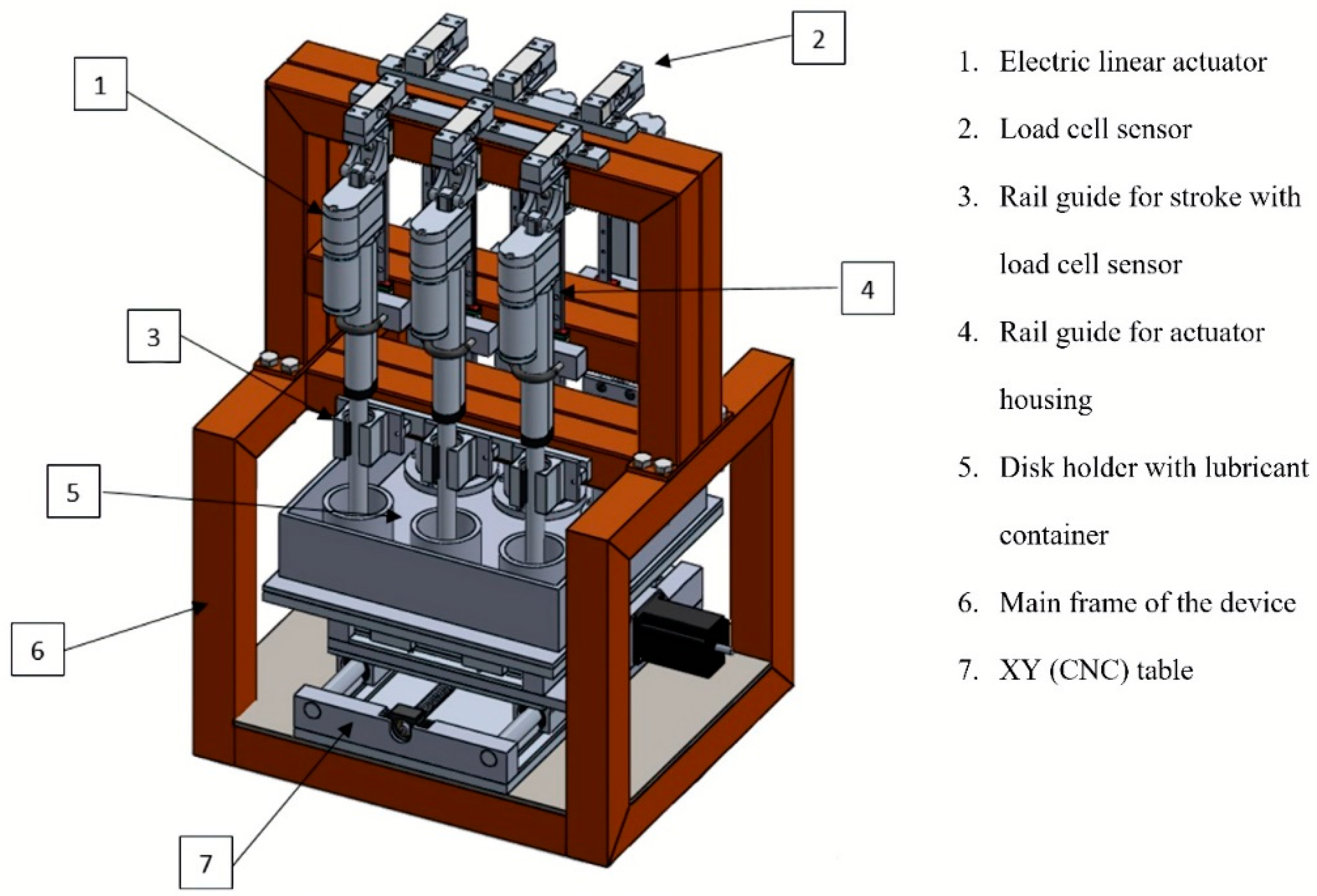
2.1. The Computer-Numerical-Control Pin-On-Disk (CNC-POD) Wear Testing Device

The Computer-Numerical-Control Pin-On-Disk (CNC-POD) wear testing device, is modeled on the original design concepts of a basic pin-on-disk wear testing platform. Each of the six stations of this new testing device incorporates an upper bearing material (ball or pin) that is attached to a pin holder, and a lower bearing material or disk that is attached to a disk holder. The primary advantage of this classic arrangement is that any combination of candidate bearing materials can be evaluated on this testing setup. A schematic diagram of the CNC-POD with its main components is shown in Figure 1. In order to operate, the CNC-POD includes different components which are described in detail in the following sections.

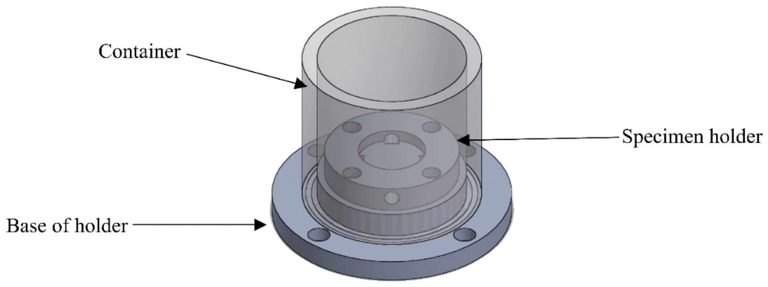
2.1.1. Specimen Holders

The CNC-POD has six testing stations. This allows us to perform six experiments simultaneously, reducing the testing time. Each chamber is composed of three parts: the specimen holder, the base of the specimen holder, and the container. Figure 2 shows the composition of a specimen chamber.

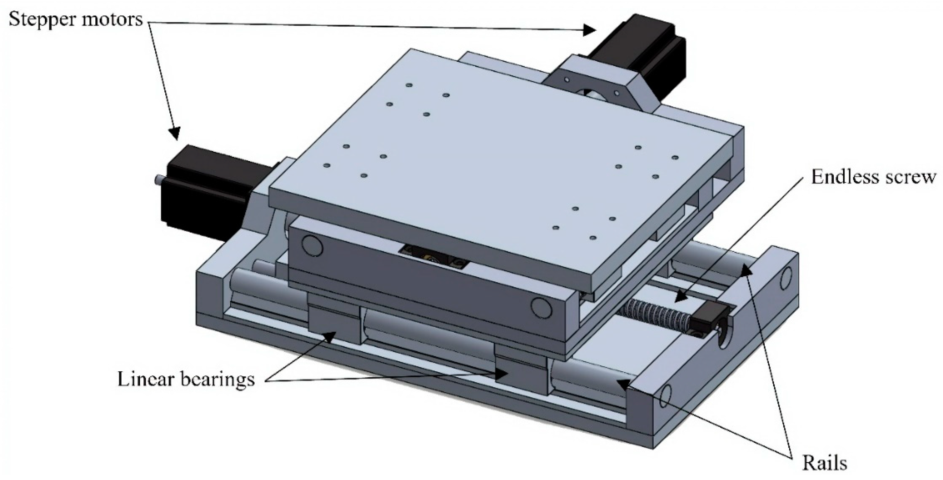
2.1.2. Motion System
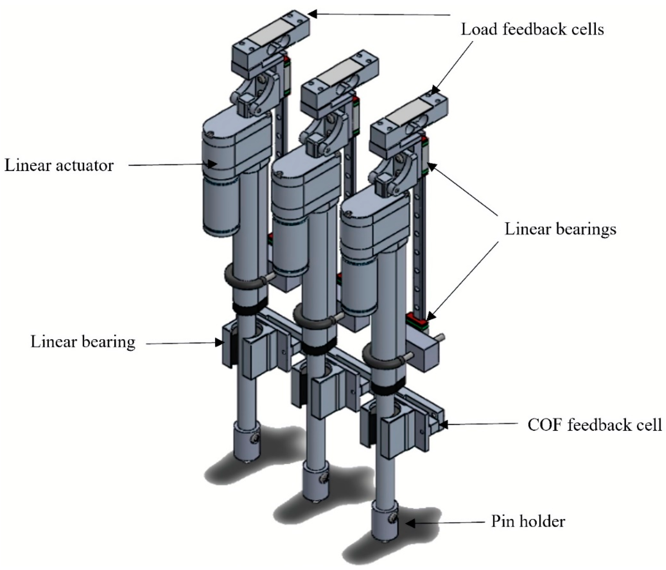
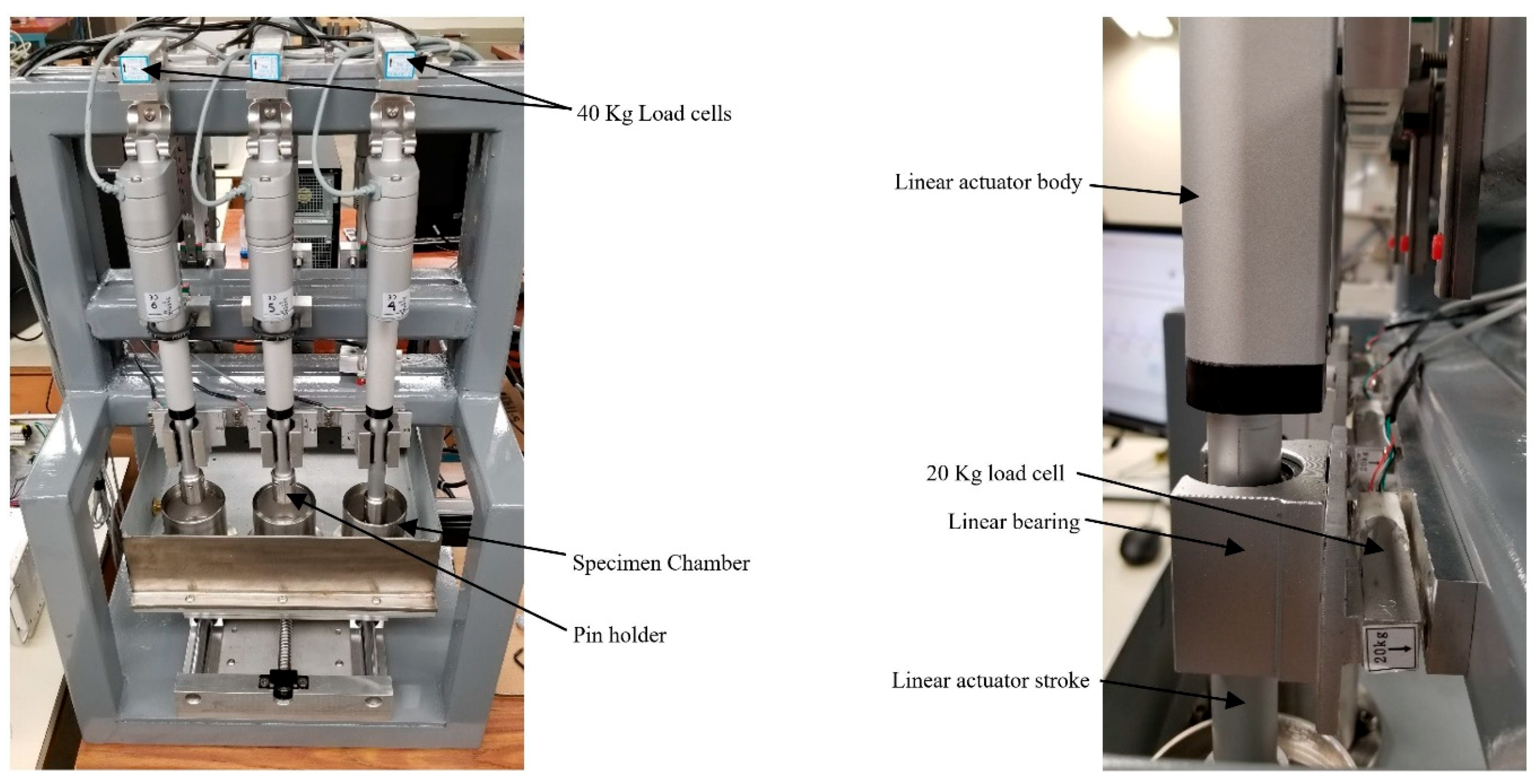
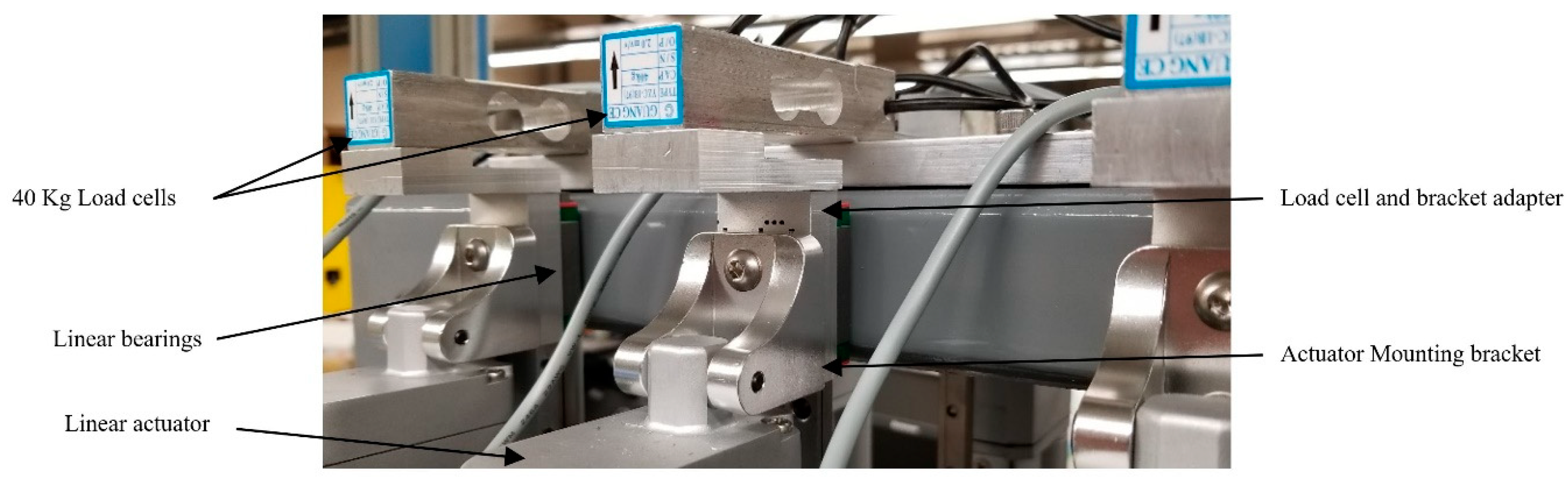
The CNC-POD can produce either unidirectional reciprocating or rectangular motion using a custom-made precision x-y traveling stage fitted with two stepper motors NEMA 24 rated for 2.8 N-m with unipolar connection and 4.0 N-m with bipolar connection. The two motors are controlled independently by means of a custom designed motion control software (LabVIEW, National Instruments, Austin, TX, USA) with two signal generator cards Microstep driver M542T (OMC Corporation Limited, Nanjing, China). Each axis of the x–y traveling stage has an endless screw which converts the motor rotation to linear motion. The endless screw drives the motion while the rest of the table is supported by four linear bearings that slide on two rails in each axis. The endless screw has a resolution of 5 mm per revolution while the stepper motor resolution is up to 0.072°, which means that the minimum displacement is about 0.001 mm per step. A schematic diagram of the motion system is shown in Figure 3.

2.1.3. Load System

In the CNC-POD design, the load is applied independently to each testing station by means of electric linear actuators. Each linear actuator is mounted on an adapter that connects the mounting bracket of the actuator to a linear bearing. The adapter holds a feedback load cell with a maximum capacity of 40 kg. This load cell allows us to monitor the load applied to the specimens. The body of the linear actuator is held by a U-bolt which is directly connected to another linear bearing. Additionally, to each linear actuator, there is a rail configuration that serves a stroke guide in order to prevent undesired motion when the load is applied. Each linear actuator is controlled independently by means of a DC motor driver VNH5019 (Pololu Corporation, Las Vegas, NV, USA). To determine the friction force during testing, a load cell (20 kg maximum capacity) was included in the design for each testing station. Each load cell is connected to a signal amplifier and then to a data acquisition card. Figure 4 shows a 3D model of the load system.

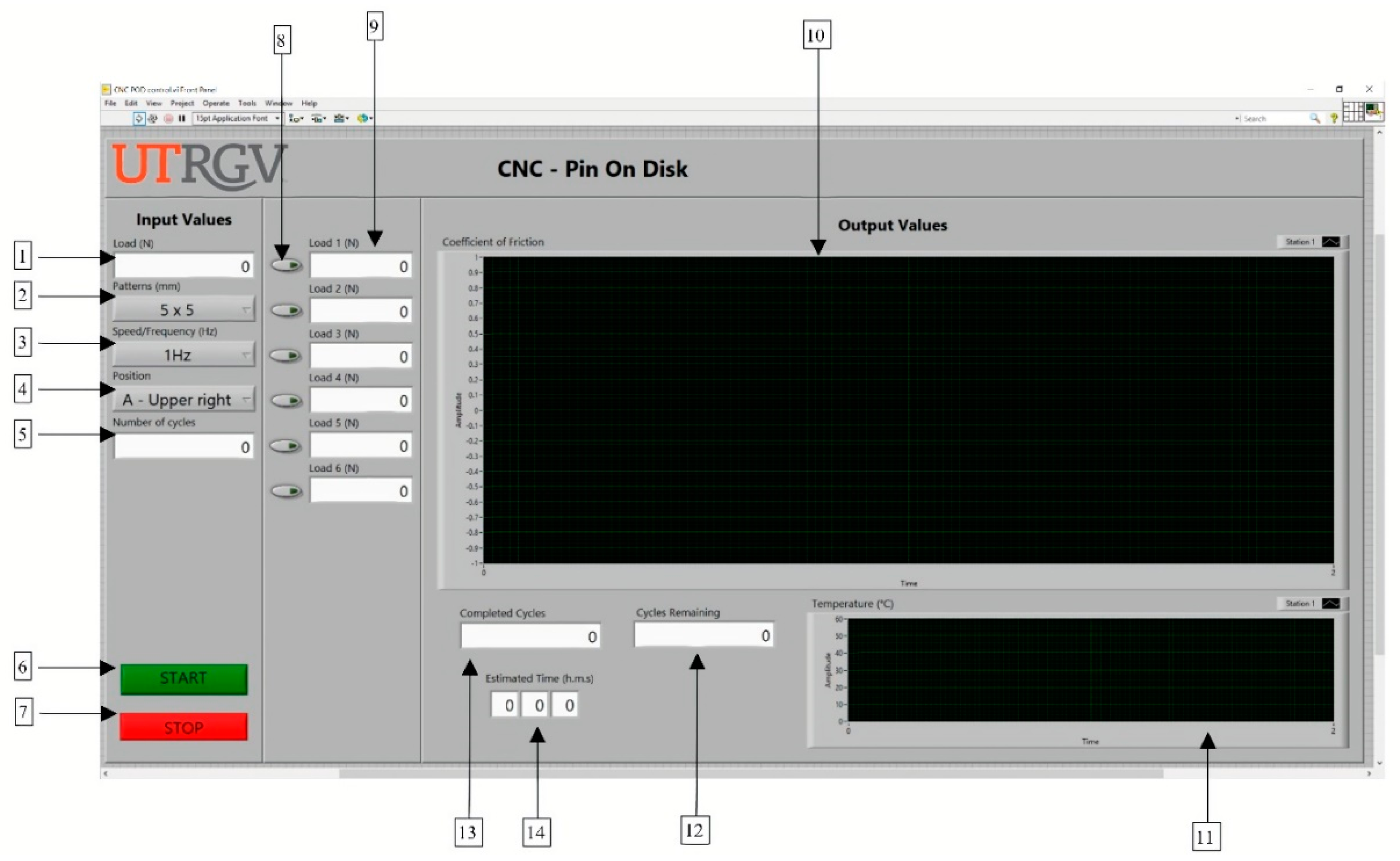
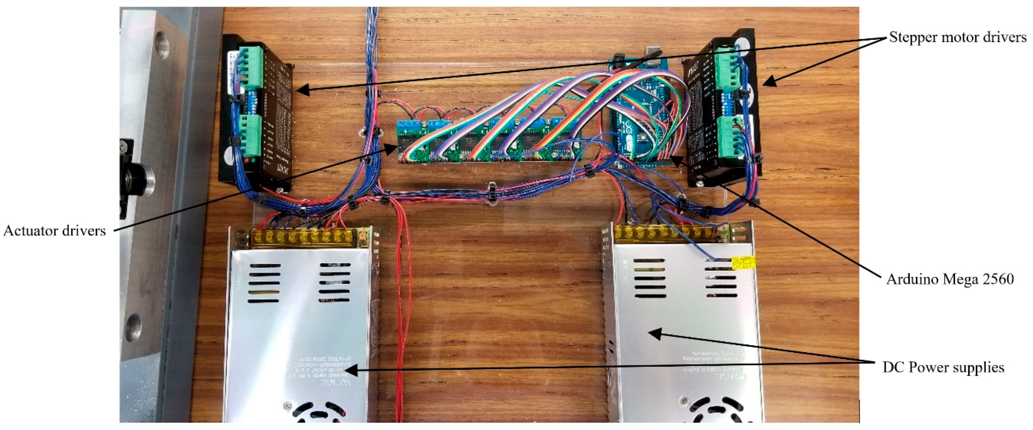
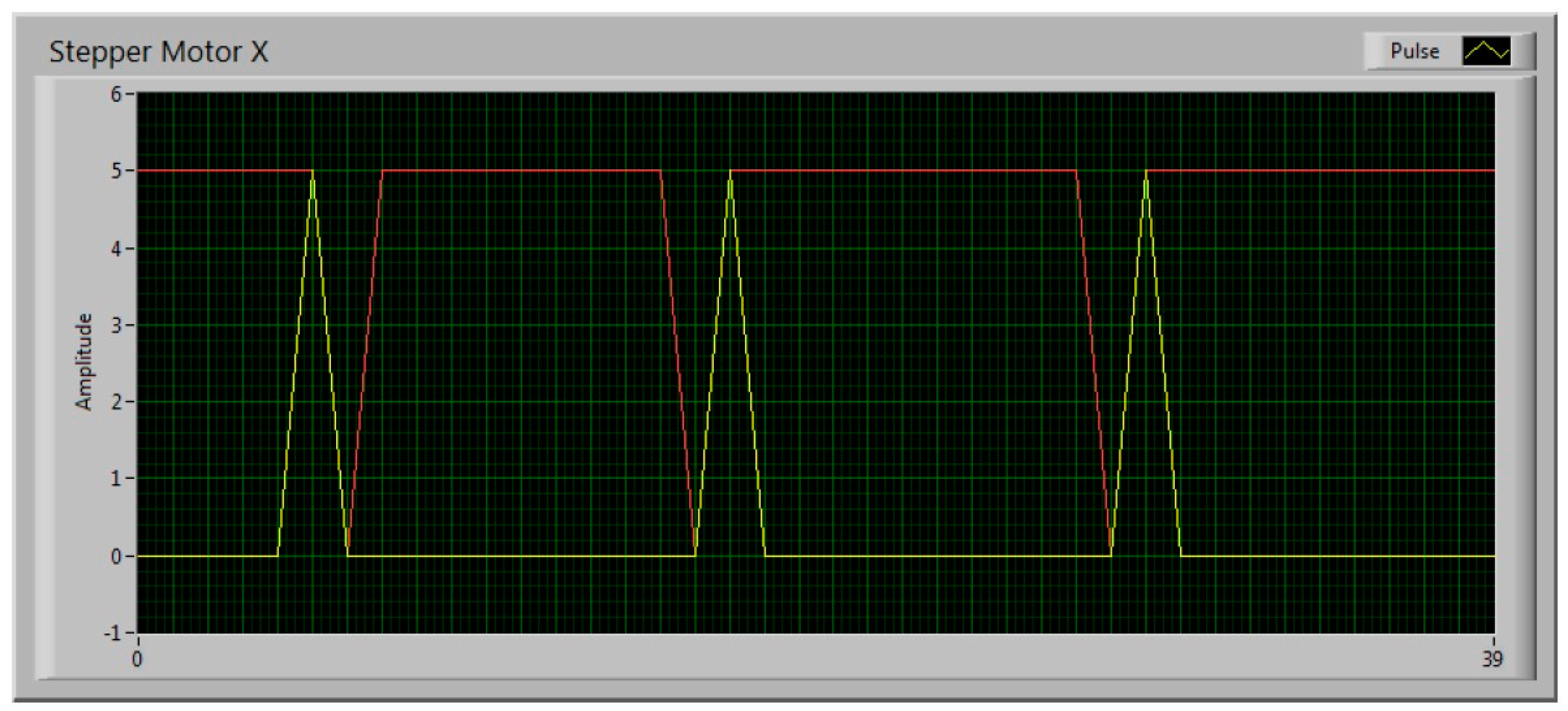
2.1.4. Control System

The control system regulates the operation of all the components in the CNC-POD; it is responsible for reproducing desired 2D patterns on the x-y stage, applying the specific load through the linear actuators, and measuring different variables during the testing. It consists of a group of drivers: Microstep driver M542T (OMC Corporation Limited, Nanjing, China), and DC motor driver VNH5019 (Pololu Corporation, Las Vegas, NV, USA) to control the stepper motors and linear actuators, respectively and sensors that communicate with a custom control software (LabView, National Instruments, Austin, TX, USA) through an Arduino Mega 2560 microcontroller. An interface or Virtual Instrument, see Figure 5, was designed to control and monitor the system. With this interface, Figure 5, the user is able to introduce input values such as: (1) load, (2) pattern dimensions, (3) frequency, (4) location of the test on the specimen, (5) number of cycles, (6) start button, (7) stop button. Output values can be monitored during testing, such as: (8) enable station button, (9) load feedback of each station, (10) in vivo COF graph, (11) remaining cycles, (12) completed cycles, (13) estimated time.

2.2. Tribological Tests

Tribological tests were performed on the CNC-POD in order to validate its design and functionality. Friction and wear tests were carried out using a ball-on-disk configuration under lubricated conditions [9,11]. The disk used during the tests was a Ti-6Al-4V ELI alloy disk (ASTM F136-13) with 28.575 mm in diameter and 6.35 mm in thickness. The disk was polished to implant grade surface smoothness, with a centerline roughness of 0.010 μm [21]. In order to concentrate all the wear on the disk, an alumina ball with 9.525 mm in diameter was used as a stationary counter body [11]. The measured hardness was 32 and 60 HRC for the disk and the alumina ball, respectively. Four different articulation patterns including a 1 mm × 9 mm, 3 mm × 7 mm, and 5 mm × 5 mm rectangles, and a 0 mm × 10 mm linear tracking pattern were digitalized into the CNC-POD [24,25]. Four wear tests were performed on the CNC-POD using the four different patterns. Each wear test was carried out using one of the four patterns at a frequency of 1 Hz [21], and a sliding distance of 20 mm/cycle [21] during 5000 cycles with a constant applied load of 30 N or an applied stress of 1.48 GPa [17,21,26]. The lubricant used during the wear tests was Ringer’s solution (8.6 g/L NaCl, 0.3 g/L KCl and 0.33 g/L CaCl2, using deionized water). The temperature of the lubricant was maintained at 37.0 °C throughout the testing procedure [21]. Wear was determined gravimetrically using an electronic balance Mettler Toledo XS205DU (Mettler-Toledo LLC, Columbus OH, USA) to an accuracy of 0.01 mg. Prior to the gravimetric measurement of wear, components were washed in soapy water, thoroughly rinsed in water, cleaned ultrasonically in ethanol for 20 min and then left in an atmosphere- controlled room for 24 h to dry and thermally stabilize. Weight loss was converted into volume loss using the specific density of 4.43 g/cm3 for Ti-6Al-4V ELI alloy disk. The wear tracks on the worn specimens were analyzed using a field emission scanning electron microscope (FE-SEM) ZEISS SIGMA VP (Carl Zeiss SBE, Thornwood, NY, USA). The friction force was continuously recorded during each test. The sliding tests were repeated three times for reliability and reproducibility [27,28].

3. Results

3.1. Design

The objective of the design and development of a new wear testing device capable to reproduce the “cross-shear” effect on bearing materials and to measure the COF between surfaces during testing was to expand the understanding of the impact of multidirectional motion on the wear rate of different materials. The new testing device CNC-POD designed and developed in the present research project is shown in Figure 6.
Figure 7 shows the physical assembly of the linear actuators with the feedback load cell (40 kg maximum capacity). To connect the linear actuator with the load cell, an actuator mounting bracket is required. This mounting bracket is connected to a load cell bracket adapter, which is assembled to the load cell and to a linear bearing. The linear bearing allows displacement when the linear actuator expands.
Preliminary assembly of the control hardware including two stepper motor drivers (Microstep driver M542T), six actuator divers (VNH5019), an Arduino Mega 2560 microcontroller, and two DC power supplies (12 and 24 volts) are shown in Figure 8.
As described in the previous section, the motion system includes two stepper motors that drive motion in two perpendicular linear stages. In order to obtain a specific displacement on each linear stage, a certain number of pulses must be sent to each stepper motor. Figure 9 shows the control signals versus time for the stepper motors on the x axis to generate the 5 mm × 5 mm motion pattern.

3.2. Tribological Results

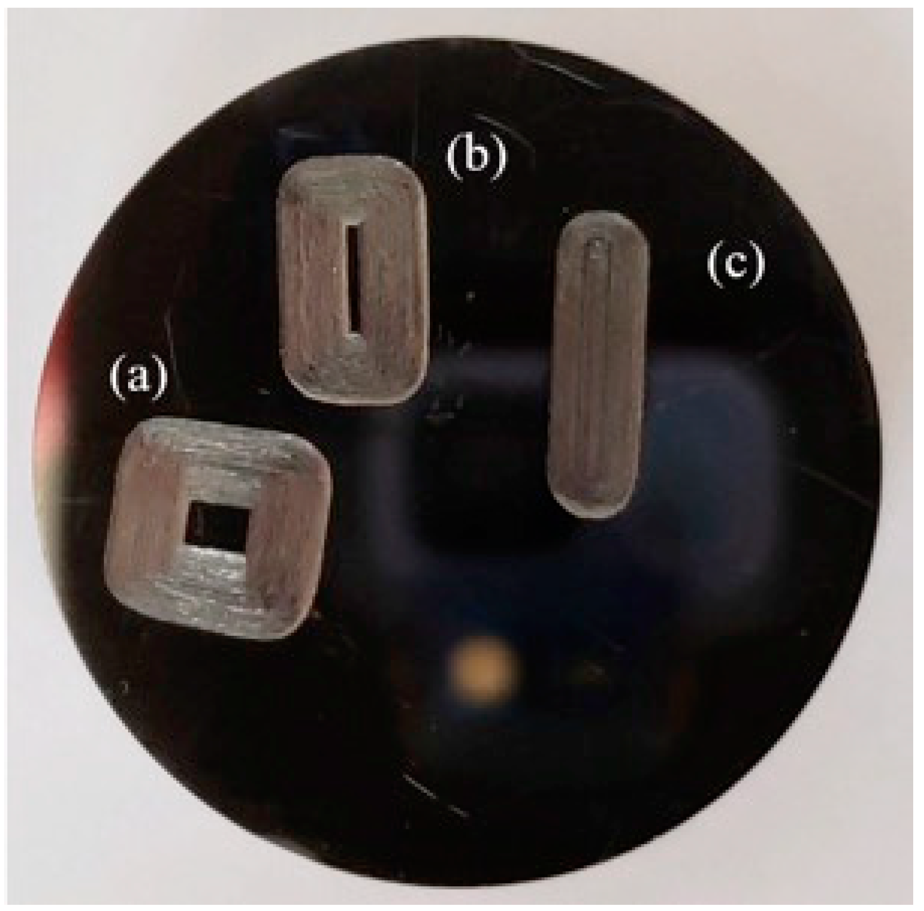
3.2.1. Gross Observation

The wear tests performed on the CNC-POD testing device created linear and rectangular wear tracks on the surface of the Ti-6Al-4V ELI alloy disks. Figure 10 shows a Ti-6Al-4V ELI alloy disk after different wear tests. The wear track corresponding to three different patterns (5 mm × 5 mm, 3 mm × 7 mm, and 1 mm × 9 mm) can be observed on the disk surface after the wear tests. Also, it can be seen that a single specimen or disk can be used to perform multiples tests. From gross observation, the linear and cross-shear portions of the wear track showed clear evidence of removed or deformed material, see Figure 10.

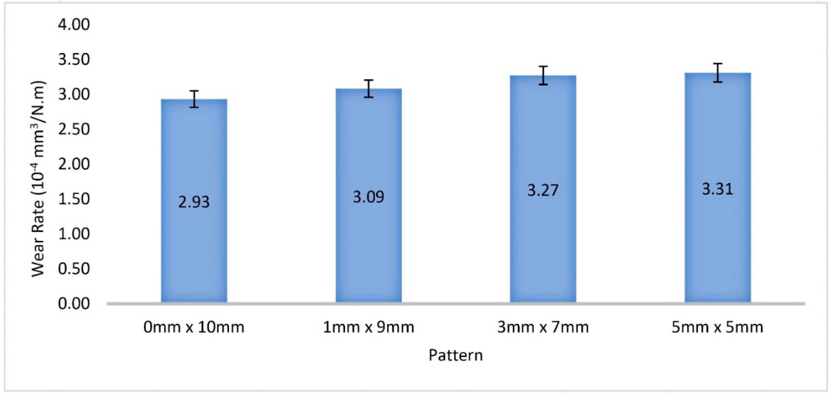
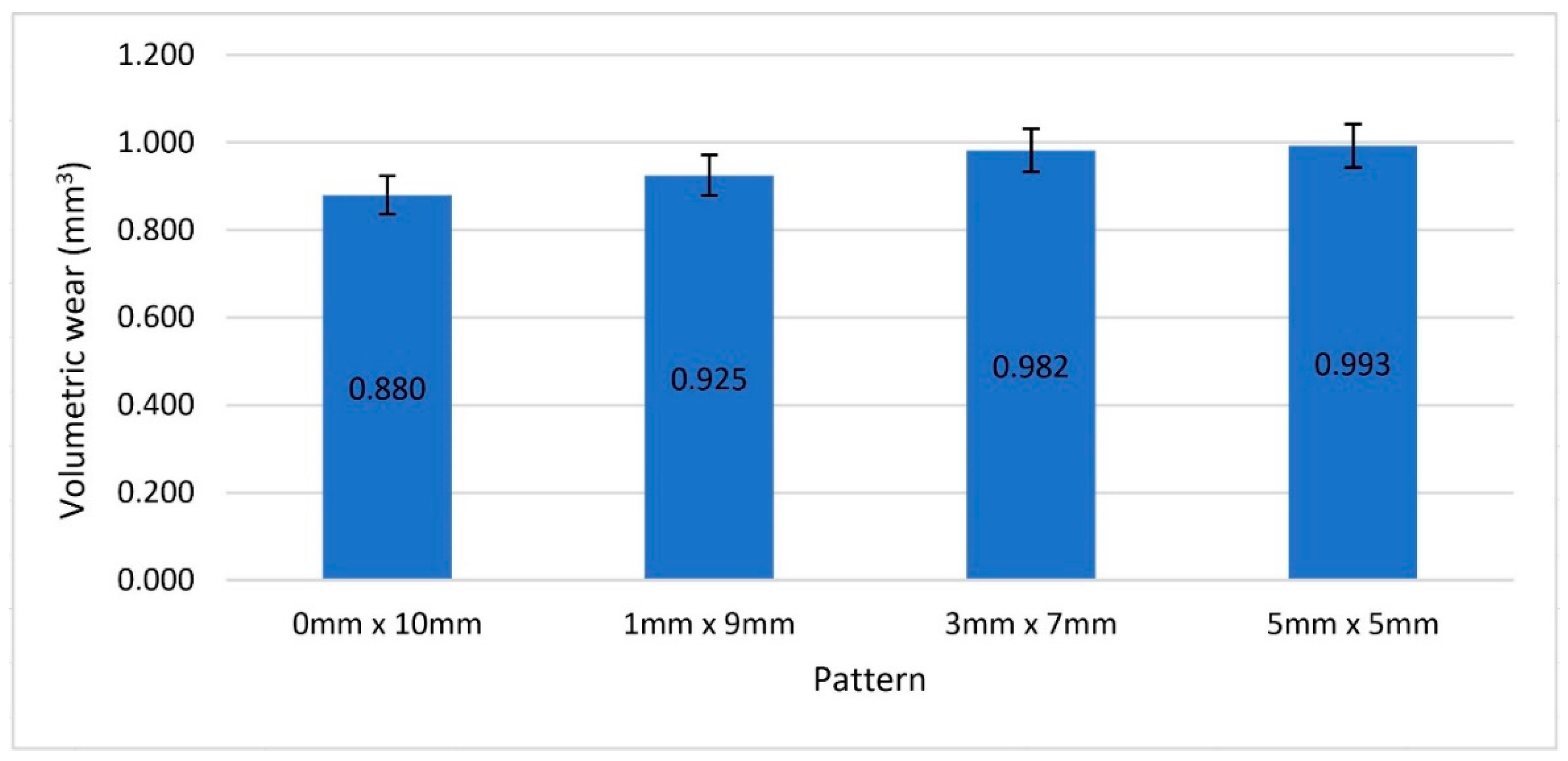
3.2.2. Volumetric Wear

Figure 11 shows the mean volumetric wear of Ti-6Al-4V ELI alloy disks tested over 5000 cycles against alumina balls using Ringer’s solution as lubricant. Wear tests results showed that the motion path pattern had an impact on the wear rate of Ti-6Al-4V ELI alloy disks. In a comparison between the more square motion path, 5 mm × 5 mm, and the more elongated (higher aspect ratio) rectangular 1 mm × 9 mm, 3 mm × 7 mm, and 0 mm × 10 mm (linear tracking) wear path, the volumetric wear rate was found to increase as the aspect ratio increased.

3.2.3. Wear Rate Calculation

In order to compare our results with the literature, the wear rate was calculated for the different patterns tested. The wear rate calculation was based on the following equation [27]:
K = V L F n d
where K is wear rate (mm3/N·m), VL is volumetric wear (mm3), Fn is applied load (N), and d is sliding distance (m). The wear rates for the different patterns are shown in Figure 12.
For the different patterns (shown in Figure 12), as the aspect ratio decreases, the wear rate increases. This is understandable, since the wear rate is dependent of the volumetric wear. The results obtained from the different experiments show wear rate values in the order of 10−4 N·m. Kang and co-workers [6] used a combined method of magnetron sputtering and plasma electrolytic oxidation (PEO) to improve the wear resistance of Ti6Al4V alloy. To evaluate the wear performance, they conducted ball-on-disc tribological tests with an applied load of 10 N against a Cr steel ball without lubrication. For Ti6Al4V alloy without modification, they reported a wear rate of 6.4 × 10⁻⁴ mm3/N·m. Yerokhin and co-workers [4] studied the tribological properties of Ti6Al4V alloy modified by AC plasma electrolytic oxidation (PEO). The tribological performance was evaluated by means of pin-on-disc tests under a 10 N load and up to 1000 m sliding distance without lubrication, using a ball of bearing steel SAE 52100 as a counterface. For Ti6Al4V alloy without modification, they reported a wear rate of 4.5 × 10⁻⁴ mm3/N·m. These wear rate values, determined under dry conditions, are greater than the wear rate found for the 5 mm × 5 mm pattern in our experiments (3.31 × 10⁻⁴ mm3/N·m) lubricated with Ringer’s solution. However, they have the same order of magnitude. On the other hand, Simsek and Ozyurek [10] studied the tribological performance of Ti6Al4V alloy by means of pin-on-disc wear experiments at a temperature of 37° in simulated body fluid environment using different loads and sliding distances, and they reported wear rates in the range of 1.5 to 2.5 × 10⁻⁴ mm3/N·m. These wear rate values are in agreement with the wear rate found in our experiments for the 0 mm × 10 mm linear pattern (2.93 × 10⁻⁴ mm3/N·m) under similar lubrication conditions. However, in our experiments, as the aspect ratio decreases in the patterns from 0 mm × 10 mm up to 5 mm × 5 mm, the wear rate increases. With these results we can confirm that our proposed device, under similar conditions, is capable of obtaining similar wear rates to the ones reported in the literature. Also, we can confirm that multidirectional motion has an influence in the wear rate, as shown in Figure 12.

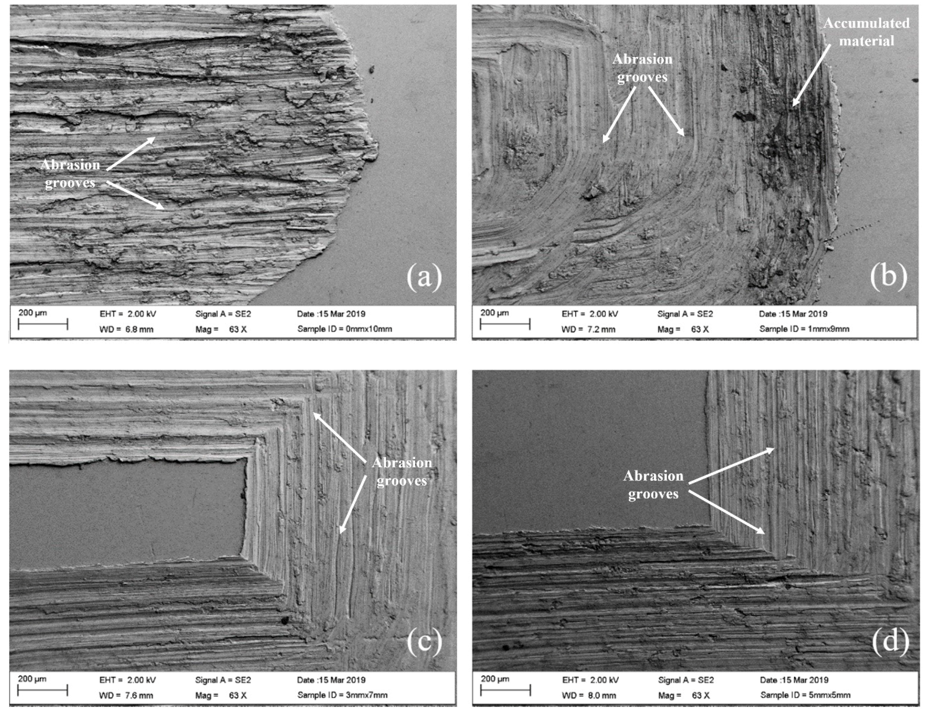
3.2.4. Scanning Electron Microscopy Analysis

SEM micrographs of wear tracks after 5000 cycles testing with different patterns are shown in Figure 13. Figure 13a shows the wear track of the 0 mm × 10 mm pattern. It can be seen that abrasion grooves and deformed material are accumulated along the wear track. The wear track of the 1 mm × 9 mm pattern is shown in Figure 13b. Unlike the 0 mm × 10 mm pattern, this image shows material removed by abrasion and detached from the surface; this may be caused due to the change of direction in the pattern. However, some of the material removed by abrasion accumulated on the edge of the shorter side of the wear scar. In Figure 13c, the wear track corresponding to 3 mm × 7 mm pattern is shown. In this image, the rectangular shape of the wear track is clearly observed, showing three sides of the rectangular path and the undamaged surface in the central part. In this wear track, abrasion grooves can be observed in some areas and it seems that part of the material removed by abrasion was smeared on the wear track. However, unlike the wear tracks analyzed before, accumulated material is not observed on the edge of the shortest side. This phenomenon could help to explain the volumetric wear results. The wear track of the 5 mm × 5 mm pattern is shown in Figure 13d. In this figure, there is a perfect corner on the wear track with a squared surface in the center without any damage. In this image, the abrasion grooves prevail in the wear track and accumulation of material on the edges is not detected, which could indicate that the material removed by abrasion was completely detached from the surface.

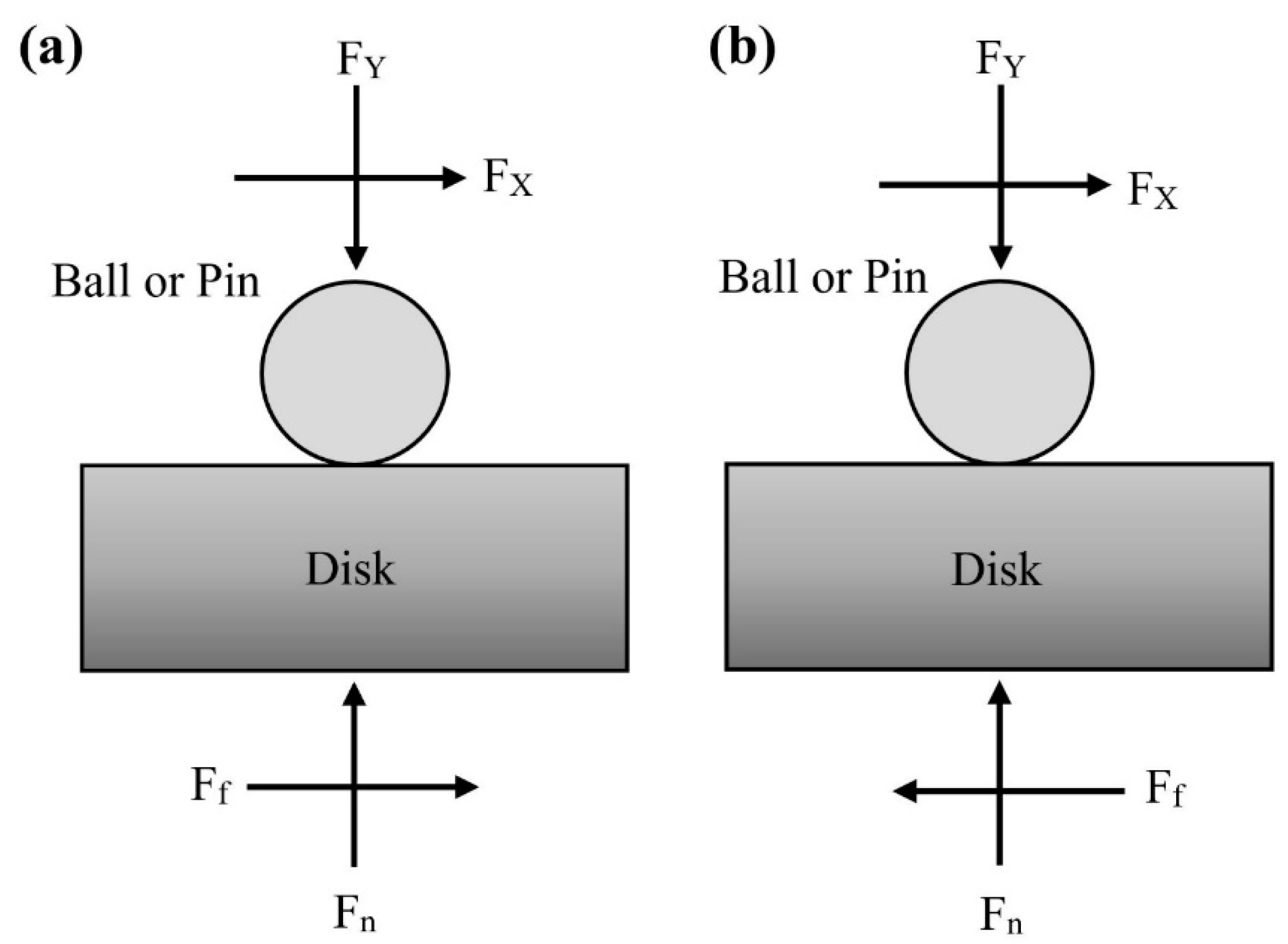
3.2.5. Coefficient of Friction

The coefficient of friction (COF) was determined by using the reversal technique proposed by Burris and Sawyer [27]. The coefficient of friction is defined as the ratio of the force resisting the motion (friction force, Ff) to the applied normal force (Fn) [27].
μ = F f F n
COF calculation requires friction force and normal force measurements. An experimental configuration is illustrated in Figure 14, where the friction and normal forces are measured by load cells. With this configuration, the disk surface defines the orientation of the load cells, and the reaction forces are equal to the interfacial forces between the ball and the disk. For the present study, the authors assumed that the disk surface and the load cell used to measure the normal force are in perfect alignment.
The measured coefficient of friction, µ′, is defined by the ratio of the load cell forces; µ′ = FX/FY. The load cell forces and the measured friction coefficient, µ′, are given by Equations (3)–(5) using a condition of static equilibrium and the definition of the interfacial friction coefficient, µ = Ff/Fn.
FX = Ff
FY = Fn
µ′ = FX/ FY
In reciprocating experiments, the sliding direction is reversed, then the friction force is also reversed as shown in Figure 14b. The measured forces and friction coefficient in the reverse direction are given by Equations (6)–(8).
FXr = −Ff
FYr = Fn
µ′ = FXr/FYr = −Ff/Fn
where, f denotes forward and r denotes reverse directions. Figure 15 shows the forward and reverse directions for the different patterns considered in the present study.
The interfacial coefficient of friction can be calculated by averaging the forward and reverse forces and dividing appropriately.
μ ¯ = 1 2 ( F X f F X r ) F Y ( A v e r a g e ) = μ
For each experiment with the different patterns, the forward and reverse FY and FX forces were continuously measured and used to calculate forward and reverse coefficients of friction. The force data from each experiment were analyzed to obtain the interfacial coefficients of friction as functions of time. The means and standard deviations of the forward, reverse, and averaged coefficients of friction are given in Table 1.
The force measurements were collected at a sample rate of 10 Hz for 5000 s. As shown in Table 1, the averaged coefficient of friction for the different patterns ranged between 0.2833 and 0.2997. These coefficient of friction values are in agreement with the values reported by Simsek and Ozyurek [10]. In their study, they reported coefficient of friction values ranging between 0.2 and 0.25 when the tribological performance of Ti6Al4V alloy was evaluated in a simulated body fluid environment.

4. Conclusions

In the present research project, a new wear testing device capable to reproduce the “cross-shear” effect with bidirectional motion on bearing materials and to measure COF between surfaces during testing was designed and built. In order to validate its functionality, tribological tests were carried out using a ball-on-disk configuration under lubricated conditions using a Ti-6Al-4V ELI alloy disk and an alumina ball. Four different articulation patterns including a 0 mm × 10 mm, 1 mm × 9 mm, 3 mm × 7 mm, and 5 mm × 5 mm were tested.
Based on the experimental results, the following main conclusions can be drawn:
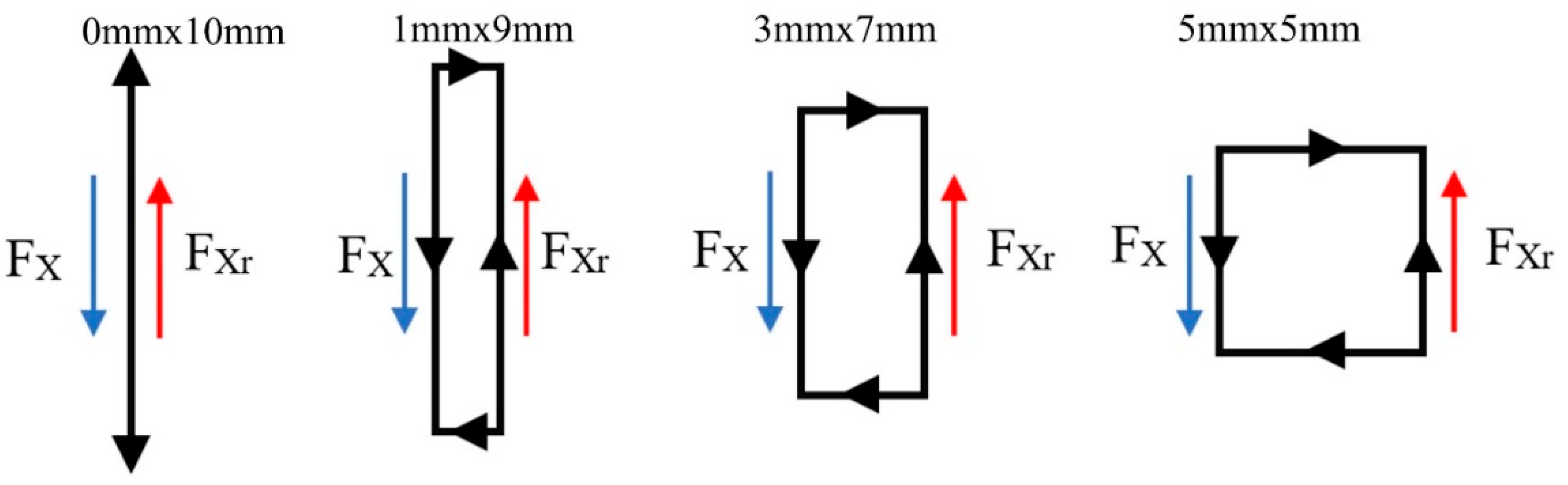
  • The x-y stage included in the motion system allows the device to reproduce a wide range of two-dimensional patterns in the millimeter scale under a specific load.
  • A maximum load of 500 Newtons (112 pounds) can be applied to each testing station through linear actuators, which can be programmed individually.
  • The CNC-POD is capable of measuring friction force during testing, and the coefficient of friction can be calculated on each testing station.
  • Motions and loads are fully programmable through LabView.
  • Six testing stations were included in the design of the CNC-POD in order to perform up to six wear tests simultaneously.
  • Multidirectional motion seems to have an impact on the wear rate of the biocompatible alloy Ti-6Al-4V ELI. However, more extensive experimentation is required to confirm these results in metals.
With the development of this system, it is possible to simulate both unidirectional and bidirectional sliding motions between the contact surfaces and measure the combined effect of multidirectional motion and different loads in lubricated environments, allowing a more accurate replication of “in vivo” conditions for biomaterials. Also, with the characteristics of the CNC-POD, it is possible to perform wear tests following the specifications included in different standards such as ASTM F732 [21], ASTM G133 [22], and ASTM G99 [23].

Author Contributions

Investigation, C.A.R.B.; Methodology, C.A.R.B.; Project administration, J.A.O.; Resources, J.A.O.; Software, C.A.R.B.; Supervision, J.A.O.; Validation, V.C. and J.A.O.; Visualization, J.A.O.; Writing—original draft, V.C., C.A.R.B. and J.A.O.; Writing—review & editing, V.C., J.A.O. and H.H.

Funding

This research received no external funding.

Conflicts of Interest

The authors declare no conflict of interest.

References

  1. Bai, W.Q.; Li, L.L.; Xie, Y.J.; Liu, D.G.; Wang, X.L.; Jin, G.; Tu, J.P. Corrosion and Tribocorrosion Performance of M (MTa, Ti) Doped Amorphous Carbon Multilayers in Hank’s Solution. Surf. Coat. Technol. 2016, 305, 11–22. [Google Scholar] [CrossRef]
  2. Souza, J.C.M.; Henriques, M.; Teughels, W.; Ponthiaux, P.; Celis, J.-P.; Rocha, L.A. Wear and Corrosion Interactions on Titanium in Oral Environment: Literature Review. J. Bio Tribo Corros. 2015, 1, 13. [Google Scholar] [CrossRef] [Green Version]
  3. Balla, V.K.; Soderlind, J.; Bose, S.; Bandyopadhyay, A. Microstructure, Mechanical and Wear Properties of Laser Surface Melted Ti6Al4V Alloy. J. Mech. Behav. Biomed. Mater. 2014, 32, 335–344. [Google Scholar] [CrossRef] [PubMed]
  4. Yerokhin, A.L.; Nie, X.; Leyland, A.; Matthews, A. Characterisation of Oxide Films Produced by Plasma Electrolytic Oxidation of a Ti–6Al–4V Alloy. Surf. Coat. Technol. 2000, 130, 195–206. [Google Scholar] [CrossRef]
  5. Khorasanian, M.; Dehghan, A.; Shariat, M.H.; Bahrololoom, M.E.; Javadpour, S. Microstructure and Wear Resistance of Oxide Coatings on Ti–6Al–4V Produced by Plasma Electrolytic Oxidation in an Inexpensive Electrolyte. Surf. Coat. Technol. 2011, 206, 1495–1502. [Google Scholar] [CrossRef]
  6. Kang, S.; Tu, W.; Han, J.; Li, Z.; Cheng, Y. A Significant Improvement of the Wear Resistance of Ti6Al4V Alloy by a Combined Method of Magnetron Sputtering and Plasma Electrolytic Oxidation (PEO). Surf. Coat. Technol. 2019, 358, 879–890. [Google Scholar] [CrossRef]
  7. Tsunekawa, S.; Aoki, Y.; Habazaki, H. Two-Step Plasma Electrolytic Oxidation of Ti–15V–3Al–3Cr–3Sn for Wear-Resistant and Adhesive Coating. Surf. Coat. Technol. 2011, 205, 4732–4740. [Google Scholar] [CrossRef]
  8. Mu, M.; Liang, J.; Zhou, X.; Xiao, Q. One-Step Preparation of TiO2/MoS2 Composite Coating on Ti6Al4V Alloy by Plasma Electrolytic Oxidation and Its Tribological Properties. Surf. Coat. Technol. 2013, 214, 124–130. [Google Scholar] [CrossRef]
  9. Zhou, J.; Sun, Y.; Huang, S.; Sheng, J.; Li, J.; Agyenim-Boateng, E. Effect of Laser Peening on Friction and Wear Behavior of Medical Ti6Al4V Alloy. Opt. Laser Technol. 2019, 109, 263–269. [Google Scholar] [CrossRef]
  10. Simsek, I.; Ozyurek, D. Investigation of the Wear and Corrosion Behaviors of Ti5Al2.5Fe and Ti6Al4V Alloys Produced by Mechanical Alloying Method in Simulated Body Fluid Environment. Mater. Sci. Eng. C 2019, 94, 357–363. [Google Scholar] [CrossRef]
  11. Sáenz de Viteri, V.S.; Barandika, M.G.; de Gopegui, U.R.; Bayón, R.; Zubizarreta, C.; Fernández, X.; Igartua, A.; Agullo-Rueda, F. Characterization of Ti-C-N Coatings Deposited on Ti6Al4V for Biomedical Applications. J. Inorg. Biochem. 2012, 117, 359–366. [Google Scholar] [CrossRef] [PubMed]
  12. UHMWPE. Biomaterials Handbook: Ultra-High Molecular Weight Polyethylene in Total Joint Replacement and Medical Devices, 2nd ed.; Kurtz, S.M., Ed.; Elsevier Academic Press Inc: San Diego, CA, USA, 2009. [Google Scholar]
  13. Dumbleton, J.H.; Shen, C.; Miller, E.H. A Study of the Wear of Some Materials in Connection with Total Hip Replacement. Wear 1974, 29, 163–171. [Google Scholar] [CrossRef]
  14. Dumbleton, J.H. Wear and Its Measurement for Joint Prosthesis Materials. Wear 1978, 49, 297–326. [Google Scholar] [CrossRef]
  15. Wright, K.W.J.; Dobbs, H.S.; Scales, J.T. Wear Studies on Prosthetic Materials Using the Pin-on-Disc Machine. Biomaterials 1982, 3, 41–48. [Google Scholar] [CrossRef]
  16. Archard, J.F. Contact and Rubbing of Flat Surfaces. J. Appl. Phys. 1953, 24, 981–988. [Google Scholar] [CrossRef]
  17. Saikko, V.; Ahlroos, T. Type of Motion and Lubricant in Wear Simulation of Polyethylene Acetabular Cup. Proc. Inst. Mech. Eng. 1999, 213, 301–310. [Google Scholar] [CrossRef]
  18. Wang, A.; Polineni, V.K.; Essner, A.; Sokol, M.; Sun, D.C.; Stark, C.; Dumbleton, J.H. The Significance of Nonlinear Motion in the Wear Screening of Orthopaedic Implant Materials. J. Test. Eval. 1997, 25, 239–245. [Google Scholar] [CrossRef]
  19. Charnley, J. The Wear of Plastics Materials in the Hip-Joint. Plast. Rubber 1976, 1, 59–63. [Google Scholar]
  20. Walker, P.S.; Blunn, G.W.; Lilley, P.A. Wear Testing of Materials and Surfaces for Total Knee Replacement. J. Biomed. Mater. Res. 1996, 33, 159–175. [Google Scholar] [CrossRef]
  21. F04 Committee. Test Method for Wear Testing of Polymeric Materials Used in Total Joint Prostheses; ASTM International: West Conshohocken, PA, USA, 2017. [Google Scholar] [CrossRef]
  22. G02 Committee. Test Method for Linearly Reciprocating Ball-on-Flat Sliding Wear; ASTM International: West Conshohocken, PA, USA, 2016. [Google Scholar] [CrossRef]
  23. G02 Committee. Test Method for Wear Testing with a Pin-on-Disk Apparatus; ASTM International: West Conshohocken, PA, USA, 2017. [Google Scholar] [CrossRef]
  24. Turell, M.; Wang, A.G.; Bellare, A. Quantification of the Effect of Cross-Path Motion on the Wear Rate of Ultra-High Molecular Weight Polyethylene. Wear 2003, 255, 1034–1039. [Google Scholar] [CrossRef]
  25. Turell, M.E.; Friedlaender, G.E.; Wang, A.; Thornhill, T.S.; Bellare, A. The Effect of Counterface Roughness on the Wear of UHMWPE for Rectangular Wear Paths. Wear 2005, 259, 984–991. [Google Scholar] [CrossRef]
  26. Baykal, D.; Siskey, R.S.; Haider, H.; Saikko, V.; Ahlroos, T.; Kurtz, S.M. Advances in Tribological Testing of Artificial Joint Biomaterials Using Multidirectional Pin-on-Disk Testers. J. Mech. Behav. Biomed. Mater. 2014, 31, 117–134. [Google Scholar] [CrossRef] [PubMed]
  27. Schmitz, T.L.; Action, J.E.; Burris, D.L.; Ziegert, J.C.; Sawyer, W.G. Wear-Rate Uncertainty Analysis. J. Tribol. 2004, 126, 802–808. [Google Scholar] [CrossRef]
  28. Burris, D.L.; Sawyer, W.G. Addressing Practical Challenges of Low Friction Coefficient Measurements. Tribol. Lett. 2009, 35, 17–23. [Google Scholar] [CrossRef]
Figure 1. Schematic diagram showing a 3D model of the CNC-POD.
Instruments 03 00035 g001
Figure 2. Specimen chamber schematic diagram.
Instruments 03 00035 g002
Figure 3. Schematic diagram of the motion system.
Instruments 03 00035 g003
Figure 4. 3D model showing the load system and its main components.
Instruments 03 00035 g004
Figure 5. LabVIEW Interface (Virtual Instrument).
Instruments 03 00035 g005
Figure 6. CNC-POD showing three testing stations.
Instruments 03 00035 g006
Figure 7. Linear actuator assembly.
Instruments 03 00035 g007
Figure 8. Control hardware preliminary assembly.
Instruments 03 00035 g008
Figure 9. Control signal versus time for stepper motor on the x axis to generate the 5 mm × 5 mm motion pattern.
Instruments 03 00035 g009
Figure 10. Wear tracks after 5000 testing cycles: (a) 5 mm × 5 mm, (b) 3 mm × 7 mm, (c) 1 mm × 9 mm patterns.
Instruments 03 00035 g010
Figure 11. Mean volumetric wear of Ti-6Al-4V ELI alloy discs tested over 5000 cycles against alumina balls using Ringer’s solution as lubricant.
Instruments 03 00035 g011
Figure 12. Wear rates of Ti-6Al-4V ELI alloy discs tested over 5000 cycles against alumina balls using Ringer’s solution as lubricant.
Instruments 03 00035 g012
Figure 13. SEM micrographs of wear tracks after 5000 cycles testing with different patterns: (a) 0 mm × 10 mm, (b) 1 mm × 9 mm, (c) 3 mm × 7 mm, and (d) 5 mm × 5 mm.
Instruments 03 00035 g013
Figure 14. Schematic representation of a common friction coefficient measurement: (a) forward sliding, and (b) reverse sliding.
Instruments 03 00035 g014
Figure 15. Force directions considered for the different patterns. Black arrows represent the sliding direction.
Instruments 03 00035 g015
Table 1. Means and standard deviations of forward, reverse and averaged coefficients of friction for the different patterns.
Patternµ′fσ (µ′f)µ′rσ (µ′r)µσ (µ)
0 mm × 10 mm0.26660.14700.30010.03500.28330.1075
1 mm × 9 mm0.29960.03450.29980.12460.29970.0975
3 mm × 7 mm0.29210.03500.29030.03260.29120.0351
5 mm × 5 mm0.30680.11020.27840.03830.29260.1088

