Article

X-ray Micro-Tomography as a Method to Distinguish and Characterize Natural and Cultivated Pearls

1
Department of Electronics and Telecommunications, Polytechnic of Turin, Corso Duca degli Abruzzi 24, 10129 Turin, Italy
2
Department of Physics, University of Turin, Via Pietro Giuria 1, 10125 Turin, Italy
3
INFN, Turin Section, Via Pietro Giuria 1, 10125 Turin, Italy
4
TecnArt S.r.l., Via Modena 58, 10153 Turin, Italy
5
RAG Gemological Analysis and Consultancy Laboratory, Corso San Maurizio 52, 10124 Turin, Italy
6
Department of Applied Science and Technology, Polytechnic of Turin, Corso Duca degli Abruzzi 24, 10129 Turin, Italy
*
Author to whom correspondence should be addressed.
Condens. Matter 2021, 6(4), 51; https://doi.org/10.3390/condmat6040051
Submission received: 15 October 2021 / Revised: 1 December 2021 / Accepted: 7 December 2021 / Published: 13 December 2021
(This article belongs to the Special Issue High Precision X-ray Measurements 2021)

Abstract

:
Digital radiography and computed tomography are two fundamental diagnostic techniques in different fields of research, including cultural heritage studies and gemmology. The application of these physical methods of investigation has gained considerable importance as they are non-invasive techniques. The presented work has been mainly focused on micro-tomographic analysis. The project is concerned with the study of natural and cultivated pearls in order to develop an investigation methodology for the analysis, distinction and characterization of different types of pearls, some of them belonging to different precious jewels from private collections. The investigations, carried out on a total of 22 heterogeneous types of pearls, allowed us to establish their origin (natural or cultivated) or to confirm/deny if a hypothesis was already expressed, and as well to highlight the cultivation methodology used case by case. Furthermore, it was possible to ascertain how large and varied the market for cultured pearls is nowadays and how difficult is, in some particular cases, to ascertain their attribution to a certain origin.

1. Introduction

The study and development of different types of instruments based on X-ray emission gained increasing importance during the last years. In particular, imaging techniques, both digital radiography (DR) and computed tomography (CT), born at first mainly for medical aims, are now widespread in many other fields of application, including cultural heritage, thanks to the strong penetrating power of X-rays, imaging analysis applied to objects of artistic and cultural interest are widely used as non-invasive methods, i.e., they do not require a sample [1,2,3,4]. These techniques allow the visualization and study of the internal structure (thanks to the different attenuation coefficient of the materials), obtaining valuable information about the nature of constituent materials, constructive techniques and the state of preservation. In the cultural heritage field, objects are very different in shapes, sizes and composition. To carry out tomography in all the cases a single set-up is not sufficient because it can be optimized in terms of resolution, field of view and crossing thickness only for an object category. Therefore, there are different experimental set-ups: a few of them have been developed over time, starting within the framework of the “neu_ART” project, born from the collaboration between the University of Torino, the National Institute of Nuclear Physics (INFN) and the Centro Conservazione e Restauro La Venaria Reale (CCR) funded by Regione Piemonte (Italy) [5,6]. During and after the end of this project, artifacts of different nature, age and size were analyzed [7,8,9,10] and, recently, some instrumental upgrades of the systems were performed, allowing improvement of the results on small objects, increasing the resolution and reducing the acquisition time [11,12].
This work concerned the application of X-ray imaging techniques in the gemological field, in particular the study of natural and cultured pearls, for which the collaboration with the spin-off TecnArt S.r.l. and the gemological laboratory R.A.G. of Torino was fundamental: the main objective was to develop a methodology, and then a protocol, for the X-ray imaging analysis of pearl samples.
The distinction between natural (naturally produced by marine or freshwater pearl mollusks) and cultured pearls (produced as a result of human intervention) has never been simple and has become even more difficult recently with the large number of cultured pearls sold today [13]. Generally, the differences are highlighted by means of radiographic analysis or microscopic observations [14,15,16,17]. The former is a very effective method because it shows the internal structures by observing the variation of the X-rays absorption coefficient of the different elements, represented through a grey levels scale of the image. This allows the discrimination between different materials and reveals the presence of voids. In conventional radiographic and tomographic images, empty spaces and low-density materials will in fact be displayed as darker areas (corresponding to a low attenuation of X-ray photons and so a greater intensity of the transmitted radiation), while the parts with a higher atomic number will result as brighter regions due to the higher absorption and consequently low transmittance of X-rays. However, in some cases, radiographs are not sufficient for a certain identification. For this reason, the tomographic technique has recently been applied to gems and pearls [18,19,20,21], providing valuable information on the origin of the pearls through the visualization of their internal structure and the study of the X-ray absorption coefficient variation of the images in a non-invasive and non-destructive way (taking into account the preciousness of some of these objects).
In this study, micro-tomographic analysis was used in the investigation and characterization of pearl samples as a valid tool for the discrimination of their origin, while also considering the market value that these objects can reach (e.g., antique and modern jewelry). The qualitative data analysis approach adopted allowed the correct interpretation of the results obtained, thanks also to the multidisciplinary aspect of the work itself.

2. Materials and Methods

2.1. The Pearls

Pearls are an example of gems formed directly through biological processes [22,23,24]. Although both natural and cultured ones can be easily distinguished from imitations, one of the most difficult tasks for gemologists and jewelers is the distinction between natural pearl and cultured products. Pearls are gemstones that can be defined as nacreous concretions, generally globular or spheroidal shaped, produced by some species of marine or freshwater mollusks, with the same substances of their shell [25]. From the biological point of view, in fact, pearls have the same origin and the same chemical composition of the inner coating of the shell valves (the mother of pearl that the mollusk secretes). Both shells and pearls consist mainly of calcium carbonate in the form of aragonite and/or calcite crystals held together by an organic substance, a scleroprotein called conchiolin, with the presence of a small amount of water and residual substances (trace elements reflect the composition of the water of the place where the pearl is formed) [23]. By examining the section of a pearl, it can be observed that the inner structure is made up of thin concentric layers deposited by the mollusk in subsequent times [26]. The formation of the pearl occurs by the epithelial cells of the mantle, which first produce a thin organic layer of conchiolin and immediately afterwards calcium carbonate, firstly calcite in columnar form (dark brown color), and subsequently, tablets of aragonite (silvery color).

2.1.1. Natural Pearls

The formation process of a natural pearl is the result of an accidental circumstance during the life cycle of a mollusk [25]. This can begin when some mantle epithelial cells are transferred into the connective tissue, where the so-called “pearl bag” is formed. Generally, this cell transfer can occur when a damage is undergone, e.g., the introduction of a foreign body (a parasite, a small shell fragment or, more generally, an irritant) that cannot be expelled.
The irritation leads, for defensive purposes, to the isolation of the foreign body and the subsequent deposition of thin concentric layers of conchiolin and calcium carbonate on it. Recent studies have suggested that the presence of a foreign body is not so necessary for their formation and even a damage in the tissue is enough [26]. Generally, a pearl takes some years (from 5 to 10 years and beyond) to reach its final maximum size.
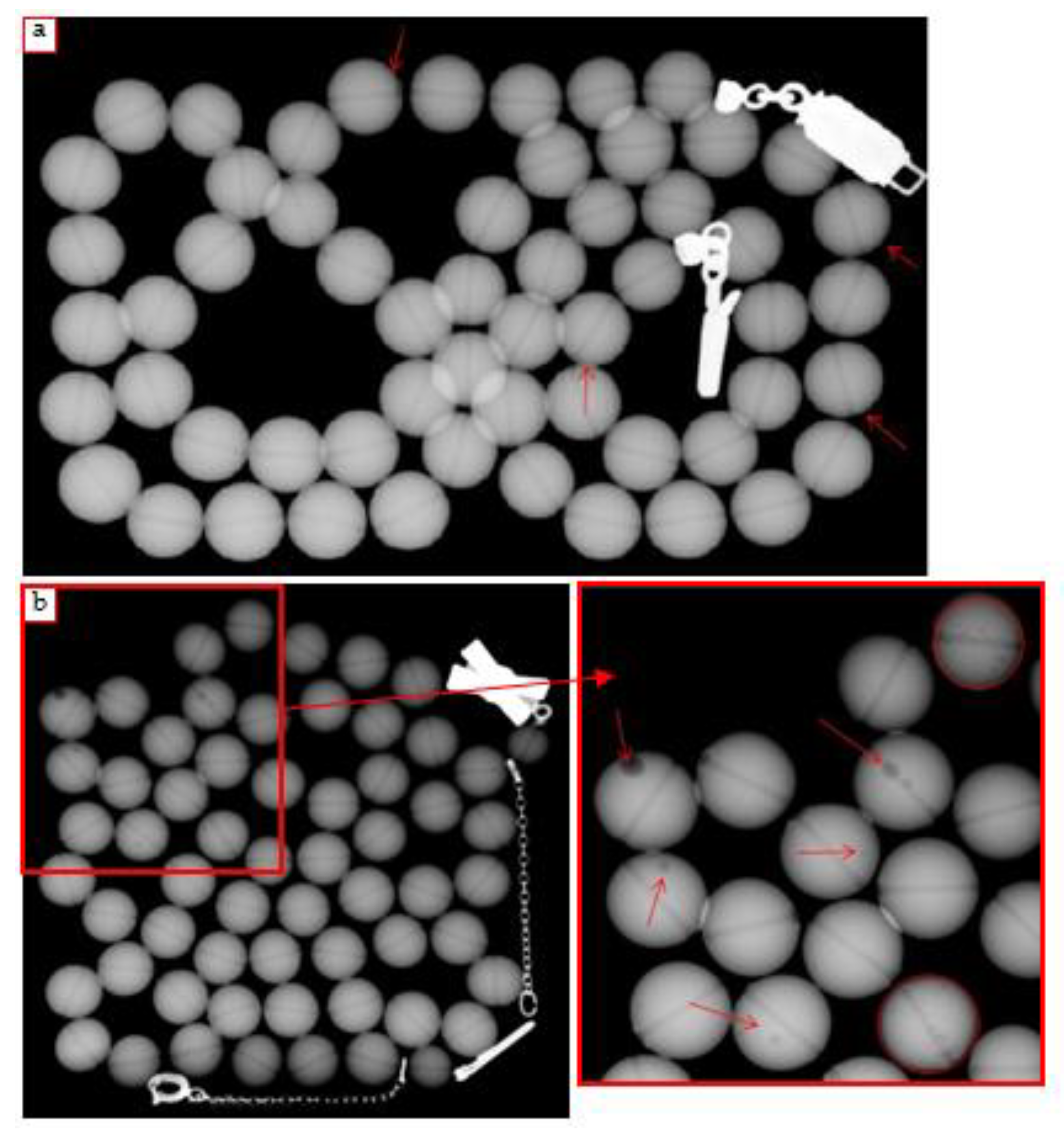
Natural pearls are thus mainly characterized by an internal “onion” structure, with aragonite and conchiolin circular layers. The images obtained using the micro-CT technique on natural pearls show the described growth structures and, since the internal region generally contains a greater amount of organic material, it will appear darker in CT images (less X-ray absorption, Figure 1a). In addition, other details such as cracks and drying due to aging that generally partially follow the growth rings could be observed. For this reason, it is necessary to pay attention in order to avoid erroneous interpretation of the pearl origin [18].

2.1.2. Cultured Pearls

Cultured pearls are formed by the insertion of a rigid core (small mother-of-pearl sphere or other materials) into the mollusk together with a mantle portion, typically in saltwater species, or an organic core (epithelium fragment), typically in freshwater ones. There are essentially three types of cultured pearls: (i) beaded (with a rigid core), (ii) non beaded (with an organic core) and (iii) composite (commonly called Mabé) [13,27,28].
Beaded cultured pearls are produced thanks to the implantation of a rigid core in the mollusk, typically a mother-of-pearl sphere, to artificially stimulate the formation of the pearl. In some cases, alternative materials are used such as calcium carbonate-based spheres or small natural pearls [23], together with other types of innovative cores [29,30].
For non-beaded cultured pearls, on the other hand, the cultivation technique involves the grafting, inside the mollusk, of an organic core (section of mantle tissue), in a direct (intentional) or indirect (due to some events linked to the cultivation process) way. A particular type of this gem is called Keshi, non-beaded saltwater pearls, with an irregular shape, which are formed due to an accident during the cultivation phase, growing when the implanted nucleus is rejected by the mollusk itself or when the epithelium fragments giving rise to other secondary pearl bags [31,32].
The third category is the Mabé typology, composite pearls cultivated by fixing a hemispherical core of steatite covered with plastic on the inner shell of the mollusk; after the extraction of the pearls, the artificial core is replaced with a resin and the base of the bubble is capped with a layer of mother of pearl [33].
Generally, beaded pearls are easy to distinguish from natural ones using digital radiography (Figure 1a,b) [34]; however, micro-tomography can provide a more detailed view of their internal structure. As for cultured non-beaded pearls, if they are formed directly from an intentionally grafted piece of living tissue, then typically the tomographic section has a small curved empty structure in the center (visible as a small dark “mustache” in the slice), which represents the grafted epithelium that could create more or less long and complex marks [18].

2.2. Instrumentation and Experimental Procedures

2.2.1. Experimental Setup

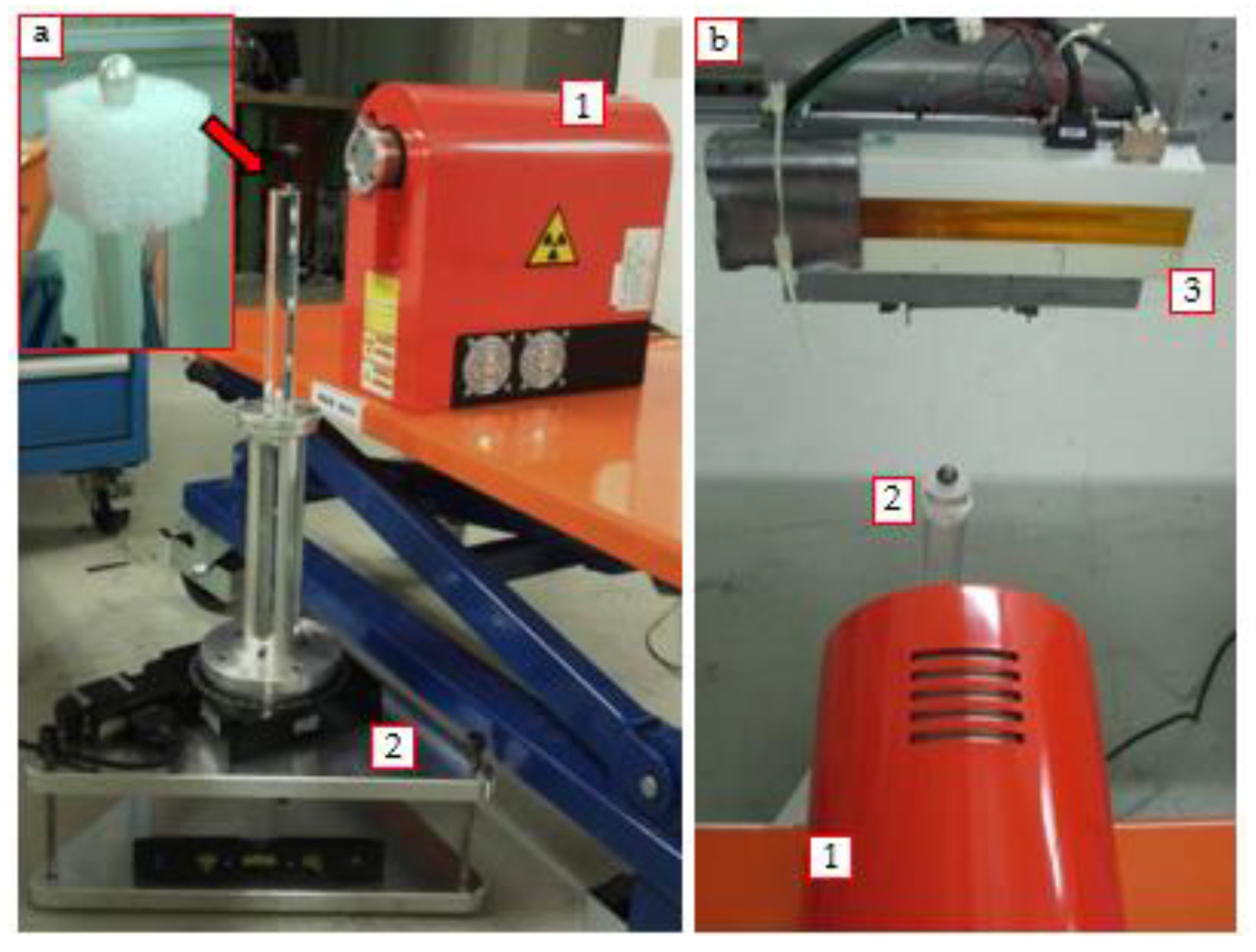
The analysis was carried out at the Physics Department of the University of Torino, where the set-up for DR and CT analysis is installed in a shielded laboratory (Figure 2). The instrumentation used consists of a Hamamatsu Microfocus L8121-03 X-ray source, associated with a digital control unit for setting and checking the operating parameters. It has a tungsten anode and the possibility to change the focal spot size up to the minimum of 7 µm (5 µm if the power is lowered to 4 W). The maximum voltage of the tube is 150 kV, with a current range from 10 µA to 500 µA and a maximum power of 75 W. The detector is a Hamamatsu C10650-321, a “linear” TDI (time delay integration) CCD detector, coupled with a fiber optic plate and a scintillator, that usually scans at 0.2–6.5 m/min. It features a 22 cm long CCD with a pixel size of 48 μm for a total pixel number of 4608×128 and it is designed for operations with X-ray energies lower than to 95 keV. The detector is installed on an automated mechanical movement system that allows horizontal and vertical precise translations, useful in the case of the DR and CT of large objects [35]. To complete the tomographic set-up, a system for a 360° rotation of the object is also essential: the rotating platform used in this case (Newport URS150BPP) together with a sample holder adapted for small objects (Figure 2a), allows small displacements (hundredths of a degree). This type of set-up allows micro-tomographic analysis and thus obtains images with a high spatial resolution (in the order of few microns). Preliminary measurements aimed to optimize the acquisition geometry and the experimental parameters for the CT analysis were performed and will be illustrated in the following section. The study involved a total of 28 pearls analyzed with DR and micro-CT, both single gems and elements of jewelry. For radiography, the detector was used in a vertical position and in TDI mode, moving it horizontally (scan speed and integration time for each pixel were of around 0.8 m/min and 460 ms, respectively); in this way, and taking into account mechanical dead time due to the movements, images of the entire objects were obtained in less than 30 s. During the CT acquisition instead, the detector was held in a fixed horizontal position (Figure 2b), using it as an “area detector” of around 220 × 6 mm2. Taking into account the magnification factor due to the geometry used, it means that an area of around 30.2 × 0.8 mm2 was investigated at the sample’s position. For each sample, the significant volume to be analyzed by means of CT, and sufficient for the aim of this work, was chosen by observing the radiographs. Moreover, the fixed position permitted an increase in the integration time for each pixel, i.e., the signal/noise ratio, and a reduction in the total acquisition time. The reconstruction of the tomographic sections was made using the approximation of fan beam geometry and the filtered back-projection algorithm [36,37] by means of two non-commercial software, one developed within the Physics Department of the University of Bologna and the other developed by Dan Schneberk of the Lawrence Livermore National Laboratory (LLNL, USA) [38], while the 3D rendering was processed using VGStudio MAX from Volume Graphics.

2.2.2. Optimization and Development of the Final Acquisition Procedure

Evaluations to determine the geometry (source–object–detector relative distances), the optimal X-ray beam energy and the angular step to be used were made and the final values selected for measurements are reported in Table 1.
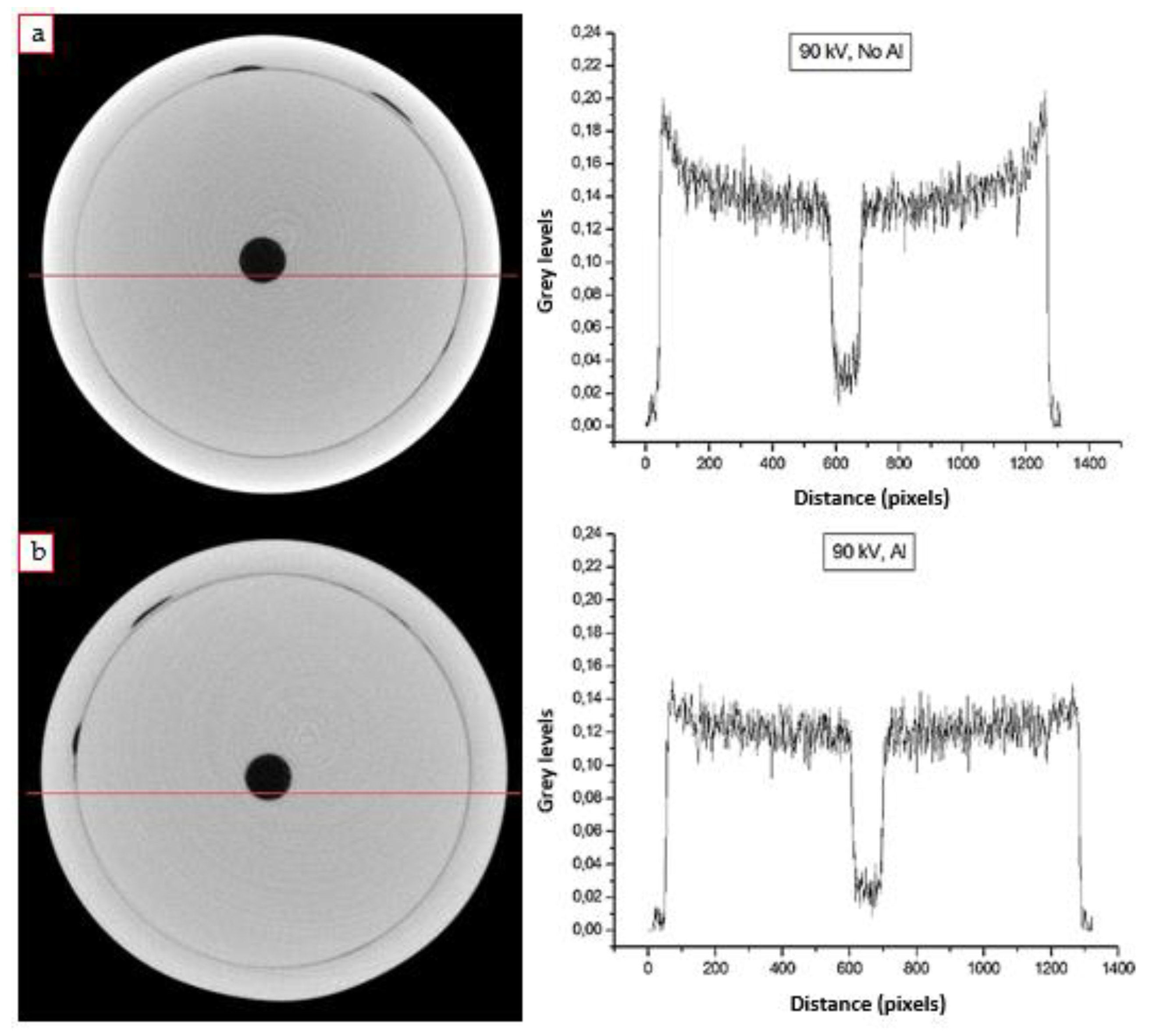
Moreover, some considerations for the reduction of artifacts that can be found in tomographic analysis were weighed, specifically for the “beam hardening” and ring artifacts [39]. The “beam hardening” effect (the progressive increase in the mean energy when using a polychromatic X-ray beam, due to a larger absorption of low-energy photons than of high-energy photons) can be identified in tomographic images as the so-called “cupping artifacts”, due to the fact that the X-ray passes a shorter distance from the edges than in the middle, resulting in an image where the edges of the sample seem more radiopaque than the central portion [39]. To limit this problem, there are different approaches, such as the use of special filters, calibration corrections and software correction [40,41]. In this work, CT scans on one of the pearl samples were performed, with and without a 2 mm thick aluminum filter, placed in front of the source window during the acquisition, in order to cut the less energetic portion of radiation. The beam hardening effect is clearly visible in the tomographic images acquired without the use of the filter (Figure 3a), where the edge of the pearl is brighter than the internal part. This is confirmed observing the X-ray absorption coefficient profile: the “cupping” artifact is evident, where the values decrease gradually moving towards the central area of the sample. In the analysis with the aluminum filter instead, the “cup” trend is no longer visible, and the values are approximately constant for the entire profile (Figure 3b). It was thus decided to use the filter for all the CT analyses, in order to limit the beam hardening effect, a non-negligible problem for the correct interpretation of the tomographic images.
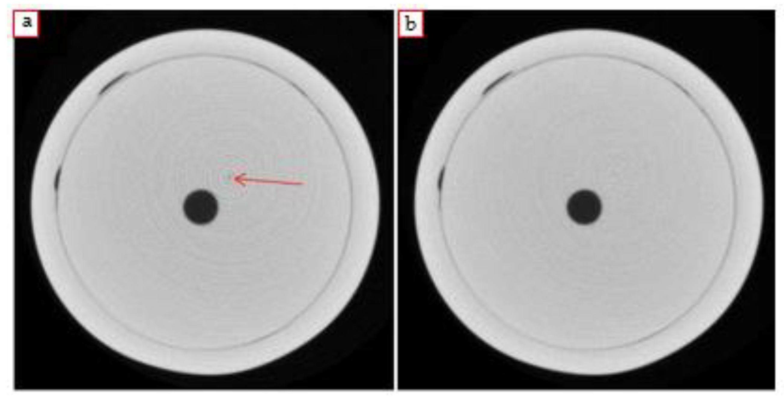
The second correction is related to “ring” artifacts: they usually are due to the detector [6] and in the tomographic sections they look like light or dark concentric rings around the rotation center (Figure 4a). In the case of micro-CT of pearls, the presence of these artifacts can lead to a partial loss of information or to a misinterpretation, because of the natural concentric internal structures of pearls. Although these artifacts can be reduced and even deleted with appropriate filters applied to the sinograms, a too strong correction can blur the image to a level that also other features are lost. For this reason, an intermediate filter has been applied by means of the LLNL software [42], that in some cases does not completely delete the artifacts, but always preserves the natural features of the pearl. A useful trick adopted in this case was not to make the center of rotation coincide with the center of the sample, in order to be able to discriminate the artifacts, if any, from the real pearl structure.
At the end of all the preliminary measurements and the consequent evaluations, it was possible to develop an operating protocol for the realization of the tomographic analysis on the pearl samples. The set conditions and parameters (summarized in Table 1) allowed an optimization of both the final results and the data interpretation to correctly classify the analyzed pearls.

3. Results and Discussion on Natural Pearls

A total of three natural pearls were analyzed: one belonging to a brooch and a pair of earrings. The results obtained from radiographic and tomographic investigations confirmed the origin of the pearls, initially supposed to be natural.

3.1. Earrings

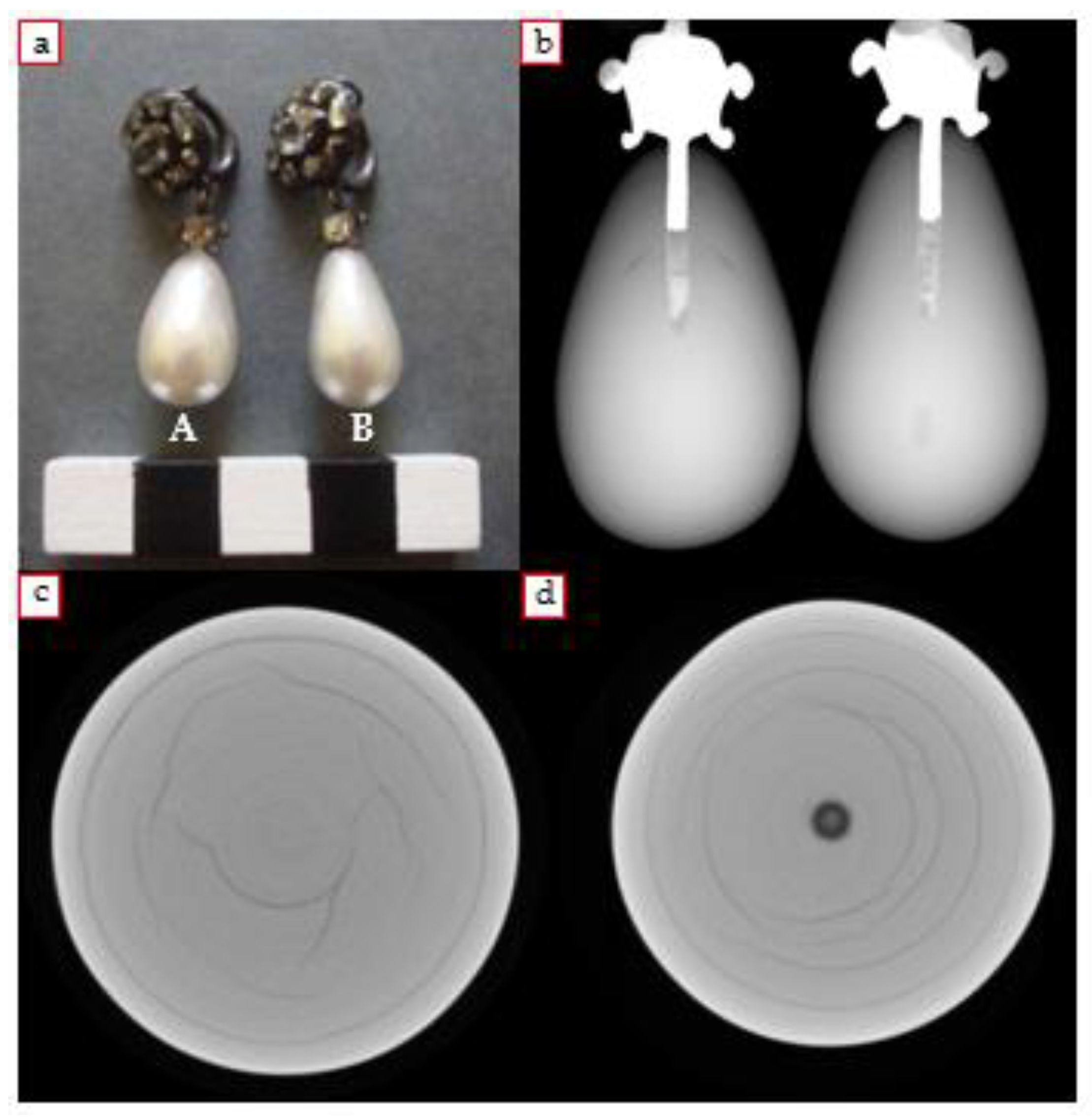
The pair of earrings, from a private collection, consisted of two natural drop-shaped saltwater pearls and diamonds set in a silver setting (2 × 1.1/1.3 cm; Figure 5a). The radiographic and tomographic analyses of the pearls were carried out also with the aim to include them into an auction and, therefore, to confirm their market value. The samples were first of all subjected to a preliminary radiographic investigation, both to allow an overall observation of the internal structures of the samples, and subsequently, to perform a more conscious tomographic analysis. The origin of the two pearls was already confirmed starting from the DR: they are clearly two natural pearls, based on the observation of the internal structures (Figure 5b). The classic onion-like conformation of circular layers, consisting of small aragonite crystals and conchiolin, is perceived in both earrings; furthermore, in earring B, a darker internal region, corresponding to an area rich in organic material, is present. Regarding the tomographic measures, the earrings were analyzed separately. Specifically, the investigation was performed making sure that the metal frame did not interfere during the acquisition. Observing the reconstructed sections (Figure 5c,d), thanks also to the good resolution obtained, the natural origin of the two pearls has been confirmed. The growth structures with a circular pattern are clearly visible and some crack can also be seen, probably due to the aging or drying of the pearl, which partly follow the growth structures; furthermore, in earring B, the darker spot in the center (Figure 5d) is referable to the nucleus consisting of calcite and a significant percentage of organic material. This structure is not always present and depends on the stage of the mantle epithelium at the moment of the pearl formation [24].

3.2. Brooch

The other sample is a beautiful brooch with a pearl (1.1 cm) and diamonds mounted on it (Figure 6a). From the DR images an extremely unique internal conformation emerged, different from the typical structure observed in natural pearl samples. In this case, in fact, a separate internal “globular” structure could be observed, less radiopaque and probably made up of conchiolin (Figure 6b). The subsequent tomographic investigation focused on a section belonging to the upper part of the sample, trying to avoid the metallic part. From the reconstructed CT slices, the inner structure of the pearl can be clearly seen and, as expected, it appears different from the more usual cases of natural pearls (Figure 6c,d). The central core had an abundant amount of organic material unevenly distributed, interspersed with lighter portions corresponding to the calcium carbonate deposit; deep fractures referable to the core of the pearl could be observed and a clear darker outline that delimits the “core” can be highlighted. One of the advanced hypotheses, after some research, concerned the attribution of the pearl to a particular category: cultured pearls with a natural pearl used as nucleus. However, after a discussion with Dr. Nicholas Sturman, a world expert in pearl identification and a supervisor at the GIA Laboratory in Bangkok [43], the natural origin of our sample was confirmed, as in some cases this kind of pearl could be formed by some particular mollusk species. These dark conchiolin-rich structures are quite common especially in Pinctada Radiata pearls. The more radiopaque areas observed in the center was referred to the points where the aragonite and organic components were mixed.

4. Results and Discussion on Cultured Pearls

4.1. Beaded Pearls

4.1.1. South Sea Pearl

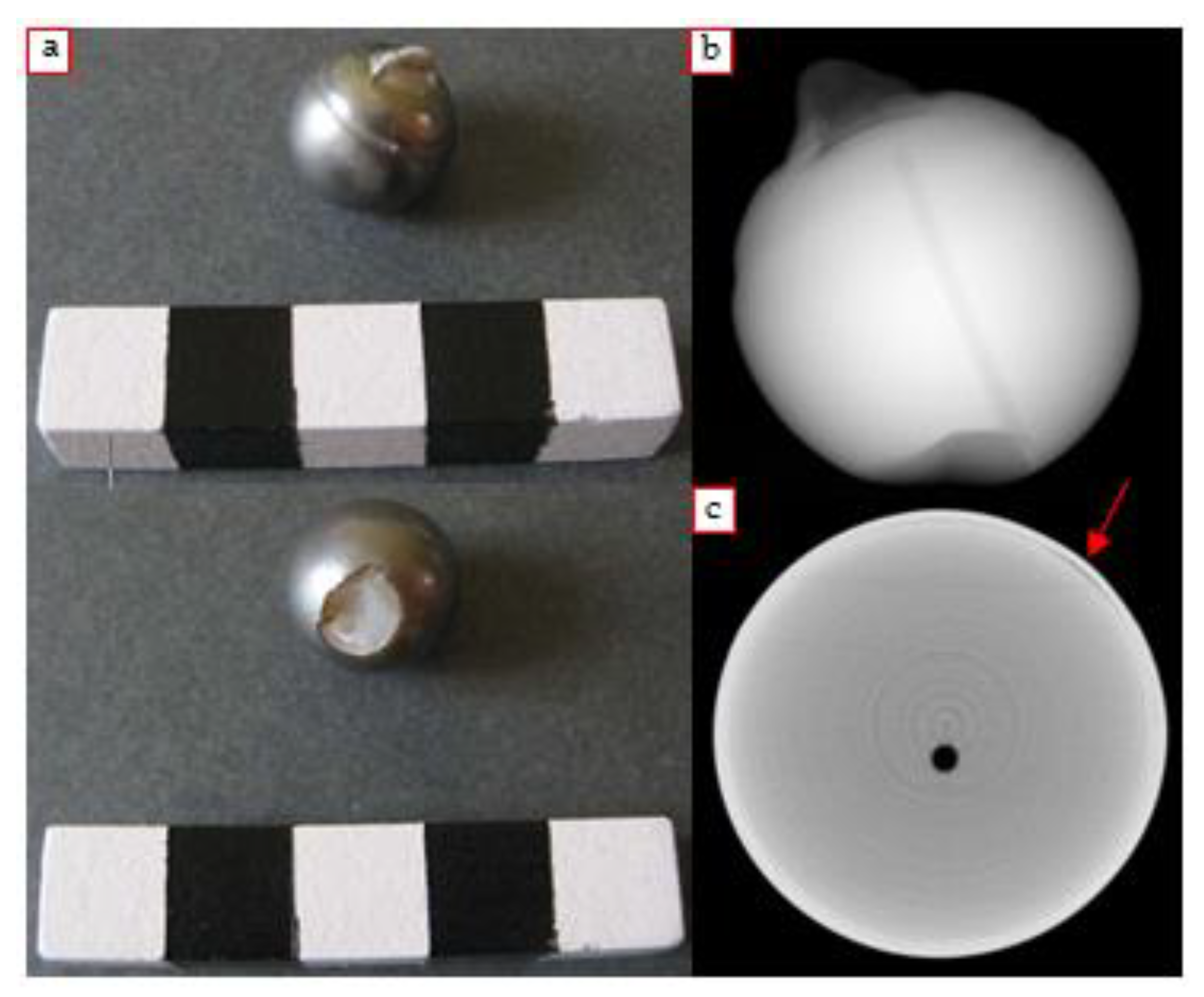
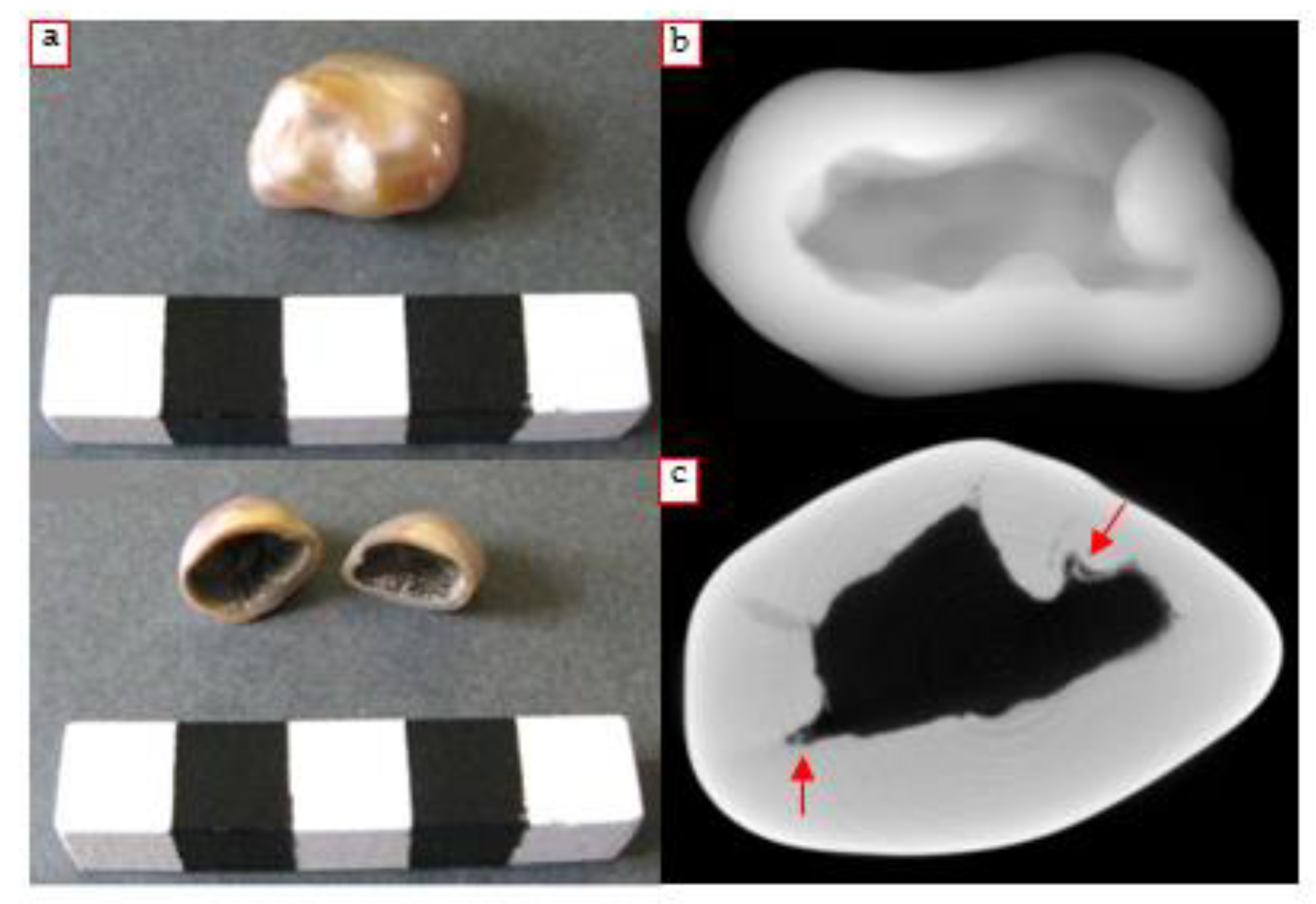
It is a type of pearl that generally has a natural color ranging from black to gray or silver, and it is produced by the black-lipped oyster Pinctada Margaritifera (Figure 7a). The commercial name derives from the fact that this category of pearls is produced mainly in Polynesia [44]. It is a particularly valuable type of pearls worldwide as they are the only cultured pearls to be naturally dark. The radiograph clearly shows the presence of a spherical core clearly visible thanks to the dark outline, consisting of the organic material secreted by the epithelium during the formation process (Figure 7b). Starting from the radiographic image, some considerations regarding the thickness of the external layer could be made, irregular with respect to the various directions (minimum and maximum thicknesses were approximately 0.3 mm and 1.3 mm). The CT sections allowed to observe in detail the internal structure of the pearl: the cultivation nucleus, perfectly spherical, is clearly visible thanks to the presence of the conchiolin layer around it (Figure 7c). The obtained results thus confirmed the nature of the pearl.

4.1.2. Irradiated Pearl with γ-rays

It is a pearl artificially treated by γ-rays irradiation, which gives a dark gray and iridescent color to the gem (0.9 cm, Figure 8a). This procedure involves the exposure of freshwater or saltwater cultured pearls, generally of poor quality to γ-rays, emitted by 60Co, trying to imitate the color of black pearls and to increase their shininess [45]. The color change of treated samples derives from both the oxidation of MnCO3 and the conchiolin denaturation. The use of gamma radiation in the color variation process can have different effects on cultured freshwater than on saltwater pearls [44]. The radiographic analysis confirmed the presence of the spherical core inside the pearl, surrounded by the characteristic dark layer of organic material, which is more abundant in the lower portion of the pearl (Figure 8b). The CT scan of the pearl revealed in a well-defined way the cultivation core and the uneven distribution of the organic material (Figure 8c).

4.1.3. Pink Pearl

It is a cultured pearl with a characteristic pink color given by chemical treatments with particular dyes (0.75 × 0.8 cm, Figure 9a). As can be seen from DR, the spherical cultivation core and the hole made in the center of the pearl are immediately evident (Figure 9b). A clearly visible feature is the X-ray transparent region in the lower portion of the sample; starting from the simple macroscopic observation, by turning the pearl upside down, the presence of an empty area that contains some irregular residues of organic substance with a strong pink color could be noticed. This corresponds to the darkest area mentioned before, attributable to a more abundant deposition of organic material in that portion. Following the protocol developed for the micro-tomographic analysis, the horizontal sections of the sample were obtained. Additionally, in this case, the CT scan, referable to the upper portion of the pearl, highlighted the clear spherical cultivation nucleus boundary and the conchiolin concentric layers deposition (Figure 9c).

4.1.4. Black Pearl

It is a waste pearl that has a dark gray color, larger than the others (1.55 × 1.8 cm). The fracture on one side of the sample allows to easily deduce that it is a cultured pearl with a mother-of-pearl core; the cultivation core, of light color, fill almost the entire volume, with an extremely thin external inorganic layer (Figure 10a).
However, in the radiographic image, the cultivation nucleus was not clearly visible (Figure 10b), while in the tomographic sections could be observed only in the upper portion of the slices; it is thus a case of cultured pearl with a core and a barely appreciable thin external layer (Figure 10c).

4.1.5. Akoya Japanese Pearl

The name “Akoya” indicates a category of cultured beaded pearls produced by Pinctada Fucata Martensii and Pinctada Fucata Chemnitzii, mainly in Japan, China, Vietnam, South Korea and Australia [46]. This species are the smallest among those that generate cultured pearls today and the resulting products are themselves generally small in diameter and perfectly (or almost) spherical. As regards the case analyzed in this work, it is a small (9 mm) Japanese pearl with a glossy white color (Figure 11a). Additionally, in this case, from the radiography, it was difficult to see the rigid nucleus because of the small amount of conchiolin deposited on it (Figure 11b). In this case, the microtomographic results, as can be seen from the slice shown in Figure 11c, proved the presence of the nucleus and confirmed the existence of an extremely thin layer of secreted conchiolin.

4.2. Non-Beaded Pearls

4.2.1. Freshwater Pearls

In all the cases studied in this work, radiographic and tomographic analysis allowed a certain attribution of the samples to this category, thanks to the identification of particular internal structures characteristic of this type of pearl (Section 2.1.2).
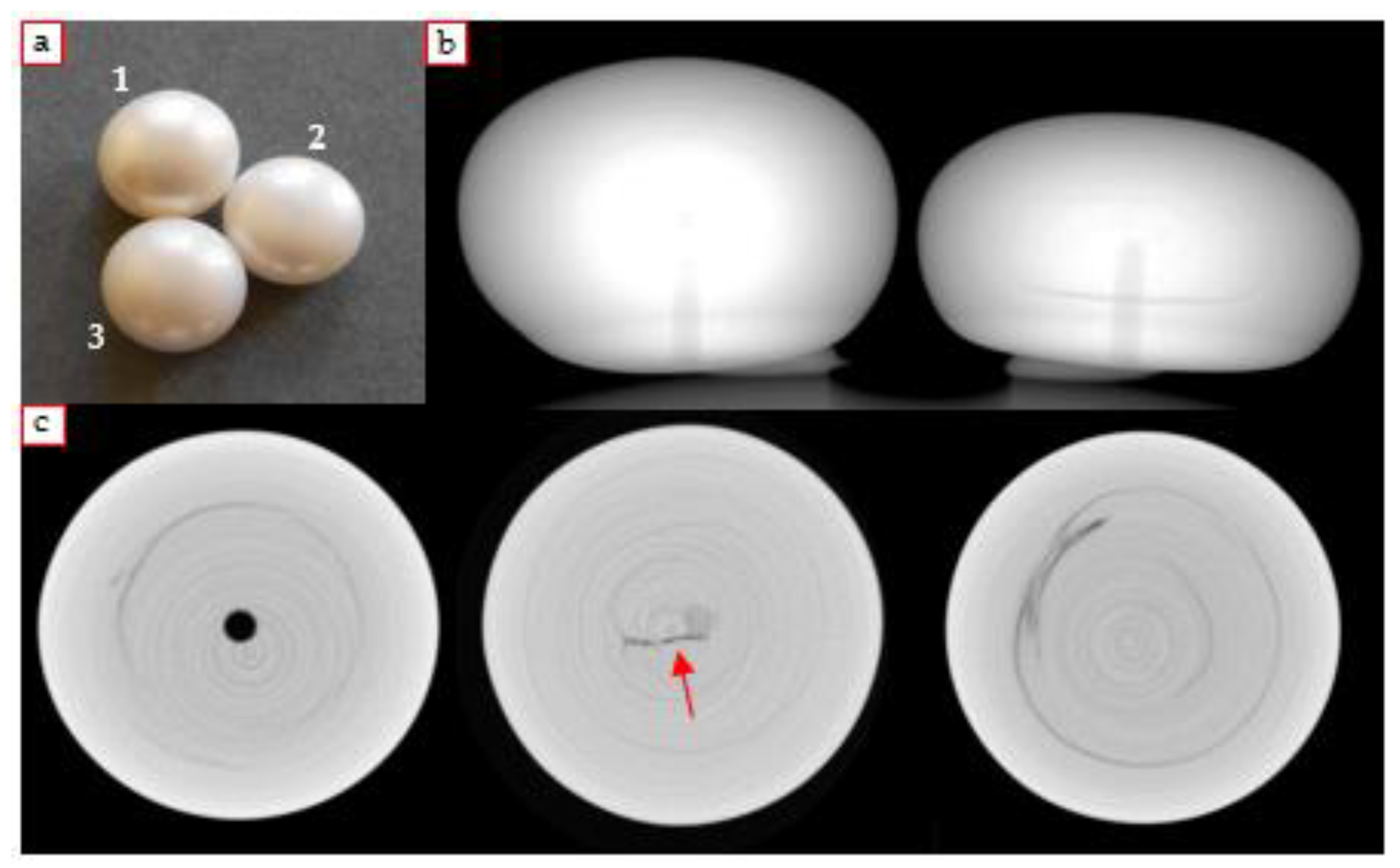
The first three samples are pearls very similar to each other, with a characteristic button shape and white color (1–1.3 cm, Figure 12a).
Radiographic analysis showed the presence of a characteristic organic structure and some concentric growth structures (Figure 12b). The micro-tomographic analysis allowed observation of the latter in more detail, which are very similar to those of a natural pearl; furthermore, in some slices also a darker area referable to the organic material could be visible (Figure 12c). In particular, from the CT images of pearl 2, the characteristic mustache typical of freshwater pearls is observed; the presence of this structure is generally a clear indicator for the attribution to the non-beaded category. Concentric growth structures can also be observed in the third sample. Furthermore, a more marked dark area and another small spot appear at different heights (observable in the lower part of the tomographic image).
Since the analyzed portion of the pearls corresponds to about 1.2 mm in height, the information obtained is referred only to a small area of the sample. The possibility to carry out other tomographic analysis of a different portion of the pearls would allow the better observation of the present epithelial tissue.
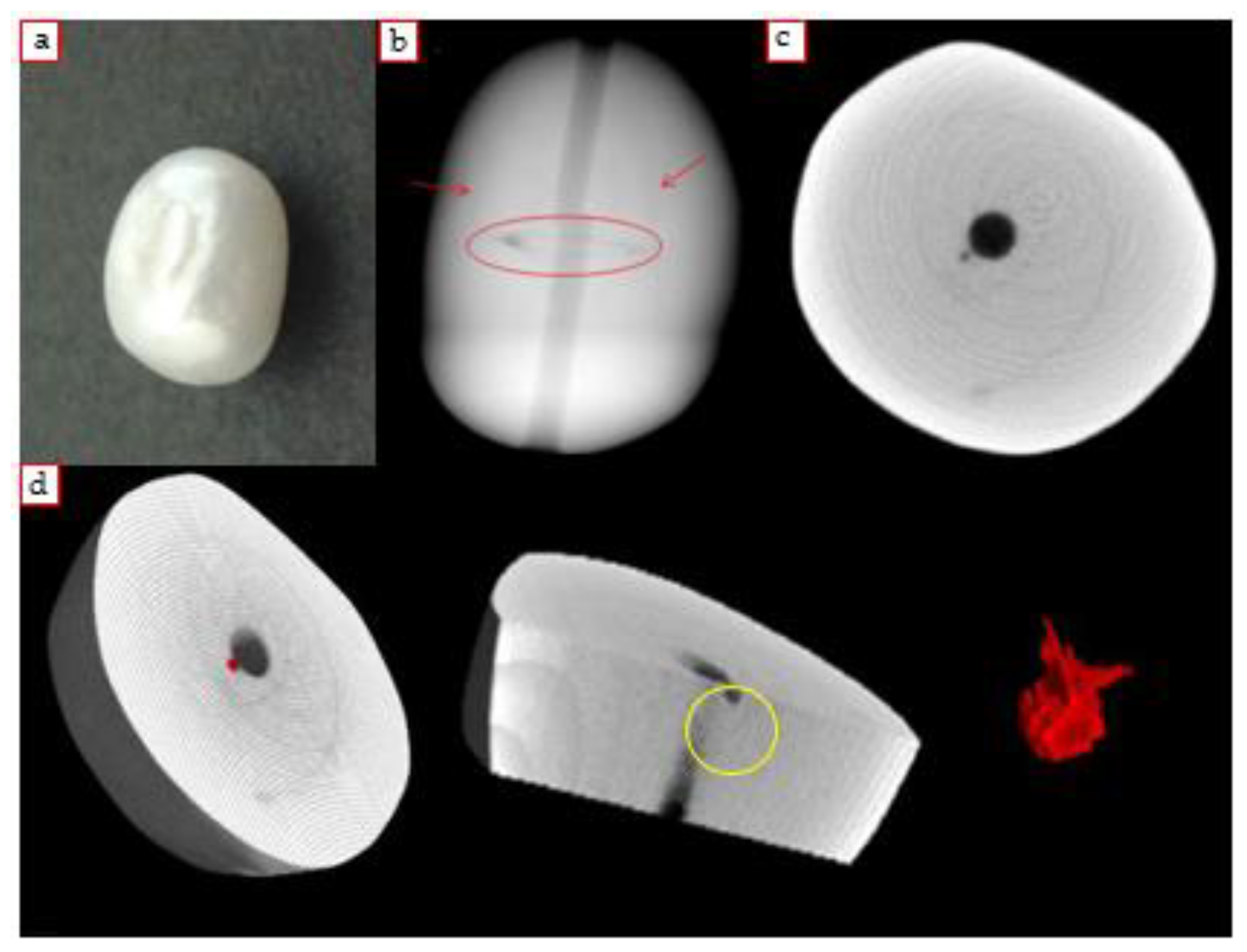
The fourth sample analyzed in this category is a Chinese freshwater pearl [47], considered at first an imitation, and subsequently to the diagnostic investigations, a non-beaded cultured pearl (1 × 0.8 × 0.7 cm, Figure 13a). It is an ivory white sample with a characteristic oval shape. From the DR, thanks to the well-defined structure that represents the original implanted tissue [30], the nature of the samples was disclosed (Figure 13b). In the micro-tomographic images, the growth structures and a small dark central spot corresponding to the cultivation tissue are observed (Figure 13c). The three-dimensional model of the analyzed portion of the pearl was also created and, thanks to the segmentation operation, an attempt to isolate the small amount of organic material identified inside was performed, in order to evaluate its shape and size (Figure 13d).

4.2.2. Saltwater Pearls (Keshi)

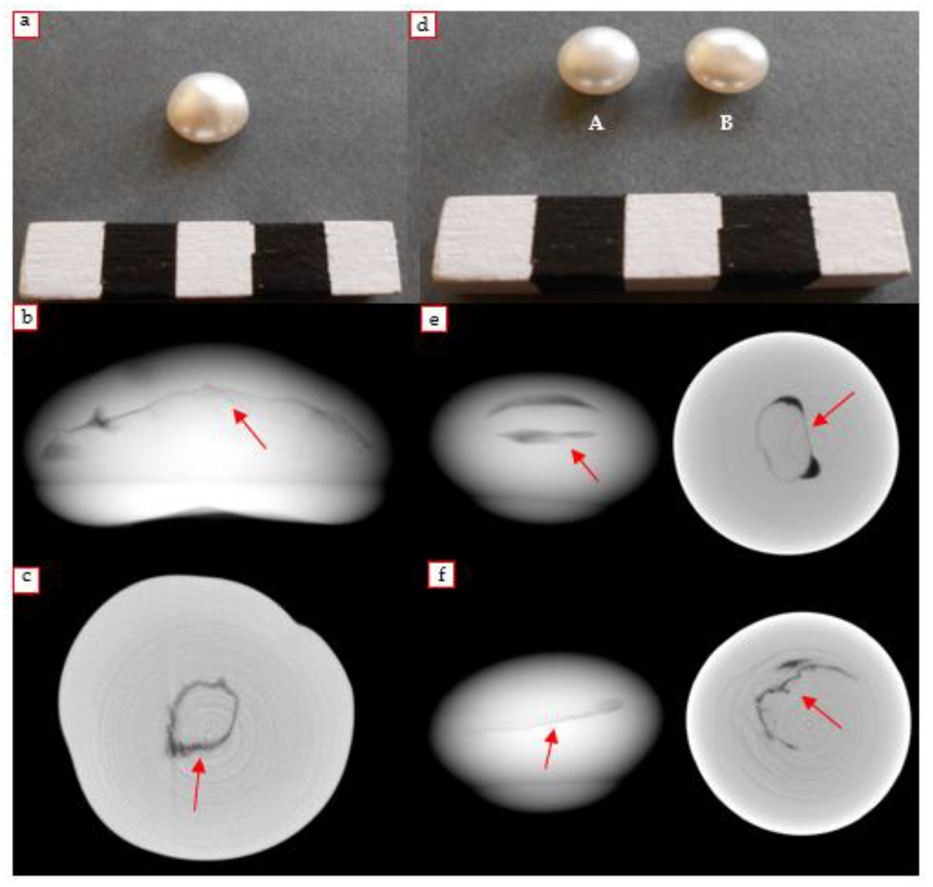
The analyzed Keshi samples in this work are three white colored pearls (1.1–1.3 cm, Figure 14a). One of these was immediately attributed to the Keshi type for sure, while the other two were classified as such only after the analysis was carried out in the laboratory. For the first pearl, the one of certain attribution, the DR revealed the typical internal structure, probably due to a collapsed pearl sack, characteristic of a Keshi pearl (Figure 14c, left). As regards the tomographic analysis, the presence of a small darker spot that widens towards the final sections can be observed (Figure 14c, right).
By examining the tomographic reconstruction, it can be hypothesized that the pearl could have been formed after the nucleus rejection during the second cultivation period, when a pre-existing pearl-producing bag is refilled with a nucleus which is then rejected shortly after [19].
The other two samples come from a jewelry store of Turin, which were received by the R.A.G. gemological laboratory accompanied by an old document from the Milan Chamber of Commerce from the 1970s in which they were defined as natural. Thanks to the potential of radiographic and tomographic techniques it was possible to undoubtedly assess that these are cultured pearls without a nucleus.
From the observation of the radiographic images (Figure 14e,f) it emerged that the Keshi A pearl seems to have a greater quantity of organic material inside than the Keshi B, regarding the analyzed portion. The tomographic images highlight the presence of abundant internal epithelial tissue in the two samples, which can be appreciated thanks to the appearance of the so-called mustache (Figure 14c,e,f).

4.3. Particular Cases

4.3.1. Soufflè Pearl

The so-called Soufflé pearls have recently appeared on the international market: they are a type of freshwater hollow pearl, very appreciated for their extreme lightness and brightness, generally with baroque shapes, considerable dimensions (up to 2 cm), different colors and extreme iridescence. The culture of these pearls involves the intentional insertion of a dried mud sphere as a nucleus, inside the pearl-bag already existing. The penetration of water causes the swelling of the mud inside the pearl-bag itself, which continues to deposit calcium carbonate on this sort of enlarged core; in this way the internal cavity typical of Soufflé pearls originates. The filtered water also causes the mud ball dissolution over time [48]. The analyzed sample has considerable dimensions and a yellow-pink color (Figure 15a). The observation of the radiographic images made it possible to investigate the structure of the Soufflé pearl and to observe the presence of a darker area attributable to the internal cavity (Figure 15b).
The latter is clearly observable in the tomographic sections, together with the thick external inorganic layer (Figure 15c). Some of Nicholas Sturman’s studies (GIA Laboratory of Bangkok) have shown the great variability of this type of pearl [48] and opened the issue on the differences among samples associated with the same category. However, the samples studied in the present work, which was from external observation absolutely compatible with a Soufflé pearl (in terms of shape, size and colors), has a less common internal conformation. Returning to the subject of variability, it could be confirmed that the identification of a pearl’s nature, which requires a lot of experience, can often be difficult and not immediately evident.

4.3.2. Beaded Empty Pearl

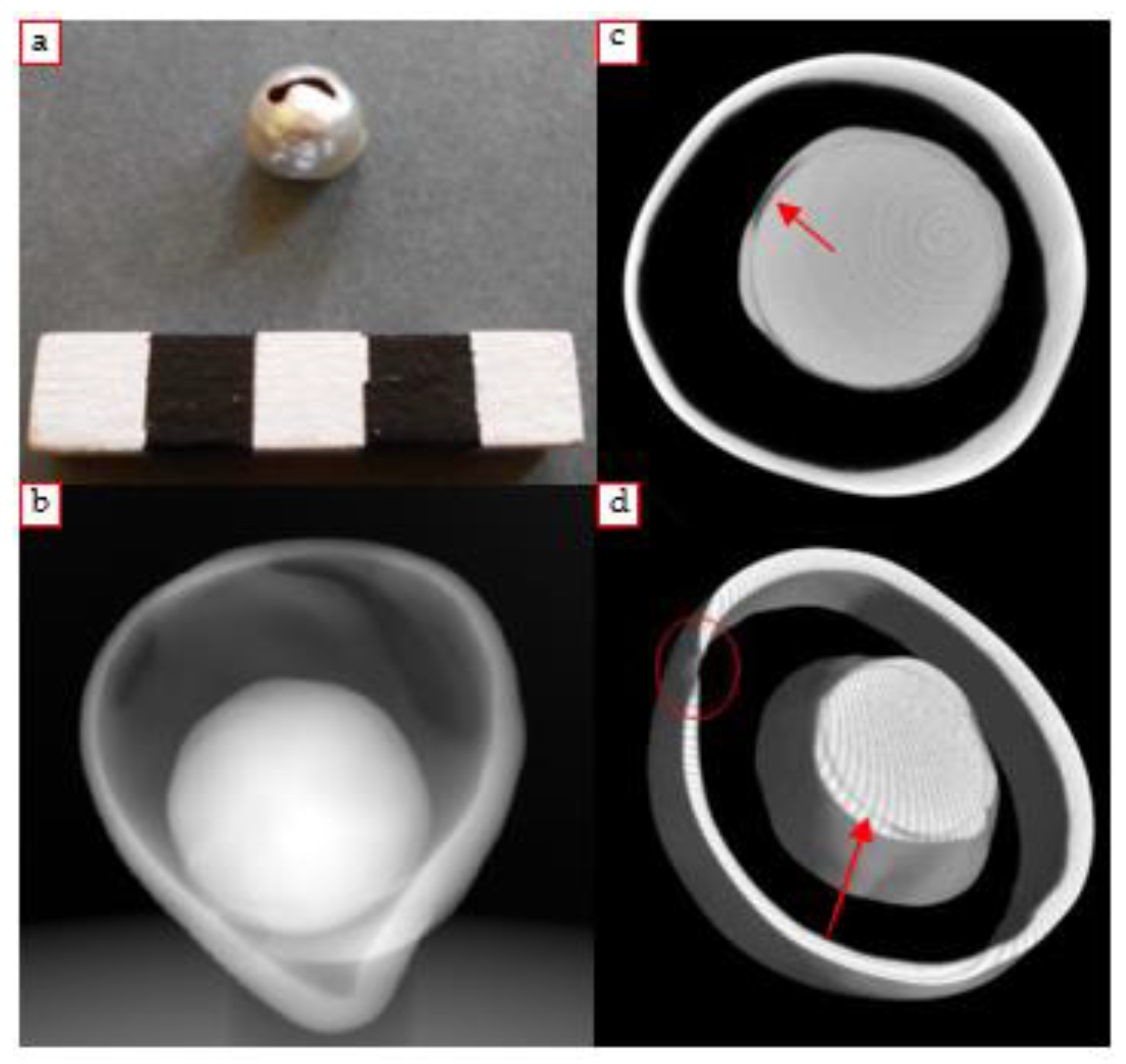
Another particular case is a cultured pearl with a completely detached spherical core, free to move throughout the internal volume of the pearl (1.3 × 1.5 cm, Figure 16a). Despite the certain nature of the sample (it was certainly a beaded cultured pearl) it was still decided to perform radiographic and tomographic analysis to study the internal structure, trying to reveal the cause of the detachment.
From the observation of the radiograph, the spherical nucleus is clearly visible; an interesting detail is that a darker circular interface (consisting of organic material) inside the core can be noticed, which seems to separate a central spherical element from a second superficial deposition (Figure 16b).
The main doubt referable to this case study mainly concerned the formation of the large internal cavity present between the rigid core and the outermost layer. From the observation of the tomographic sections, it is firstly possible to evaluate the dimensions of the free rigid core present inside, much smaller in diameter than the pearl itself (8 mm, Figure 16c). Furthermore, it is possible to notice the presence of a thin circular structure that surrounds the inner core. This thin layer represents the very first deposition of organic material carried out by the mollusk during the first step in the production process of a cultured pearl. An additional rather thin light grey layer is perceived, deposited on the organic material: this is the first layer of nacre deposited; it is thus assumed that the first step in the formation of the pearl took place regularly.
With regard to the possible cause of the detachment, based also on the reference [49] where a similar case is faced, it has been hypothesized that the organic material may have undergone a bacterial infection or contamination.
The three-dimensional model of the analyzed portion was also created and rotations in space and virtual cuts were made. The completely empty cavity located between the nacreous core and the external nacre, as well as the layer of conchiolin deposited on the internal core can be appreciated (Figure 16d).

4.3.3. Mabé Pearl

The term Mabé is the commercial name used to indicate composite pearls (Section 2.1.2) with a typical button shape. Composite beads are generally easy to distinguish already by the naked eye. Nevertheless, it was decided to apply radiographic and tomographic investigations to evaluate the internal conformation of the sample (Figure 17a).
Analyzing the radiograph, it is possible to visualize the more radiopaque external layer of nacre (in this case, with no uniform thickness for the entire perimeter of the pearl) and the internal volume filled with a material (typically resin) with a lower X-ray attenuation coefficient (Figure 17b). On the other hand, observing the tomographic sections, it is possible to better appreciate the various elements mentioned above (Figure 17c). Finally, some darker spots at the interface between the filling material and the thin layer of nacre could be noticed, probably as small air bubbles or empty spaces created during the production operation [50].
Additionally, in this case the 3D model of the analyzed pearl portion has been obtained, visible in Figure 17d.

4.3.4. Baroque Pearl

The term “baroque” is an adjective used to describe natural or cultured pearls with an irregular and non-symmetrical shape [51]. Baroque pearls are more commonly cultured freshwater pearls; in some cases, in order to give the final product a peculiar aspect, a particular shape is given to the grafted epithelial tissue (for example a stripe, extended lengthwise).
The sample analyzed in this work is a Chinese freshwater cultured pearl with a characteristic elongated baroque shape (2.9 × 1.05 cm, Figure 18a). The X-rays revealed some small dark spots distributed over the entire length of the pearl: this is the tissue used to start the cultivation process, visible more clearly in the tomographic slices. The concentric circles visible on the images are ring artifacts, not completely removed in the image processing phase (Figure 18b,c).

4.3.5. White Pearl

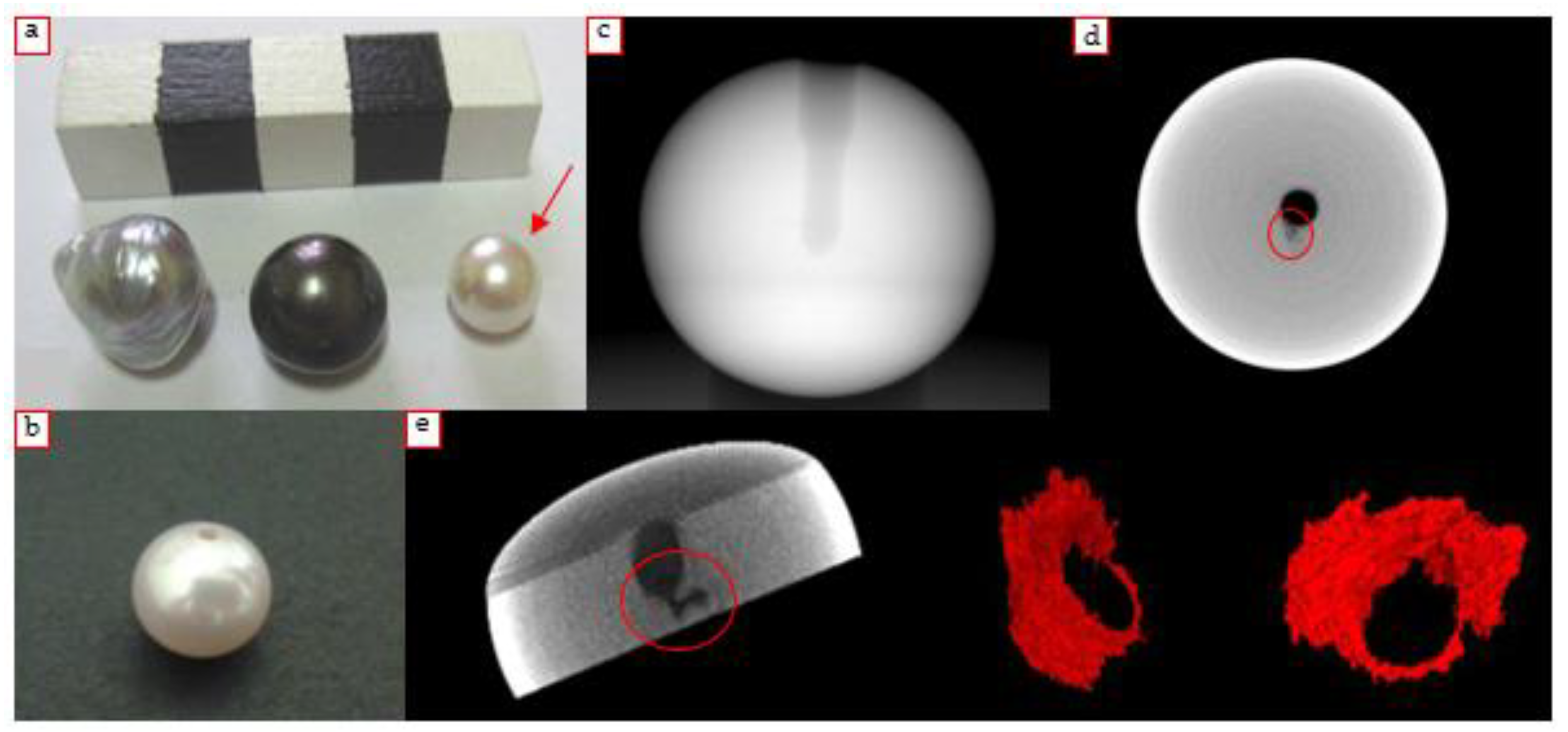
The sample is a small pearl with a perfectly spherical shape and a white color (Figure 19a,b). It arrived in the laboratory as a beaded cultured pearl, but radiographic and tomographic analysis was useful to deny this initial attribution. In the radiographic images obtained, no obvious and explicit details were found for attributing the sample to the category of beaded cultured pearls (Figure 19c). Thanks to the micro-tomographic analysis it was possible to obtain some additional information regarding the internal structure of the sample. The result of the CT scan allowed us to ascertain that, starting from a certain height of the sample, the appearance of a small dark spot could be seen, which is most likely attributable to a portion of organic material; the nucleus, on the other hand, is difficult to be distinguished (Figure 19d). The nucleus identification is in fact a problem in cases where a very thin and almost imperceptible layer of conchiolin is deposited between the nucleus and the nacre; moreover, the presence of ring artifacts can, in a perfectly spherical pearl, create confusion and disturb the observation of the internal structures.
A further issue concerns the fact that the internal structures associated with the cultivation tissue are often located in the center of the pearl; if the pearls are pierced, the hole made in the center intercepts the aforementioned structures, making difficult a certain attribution. Using the 3D rendering software and operating on the reconstructed horizontal sections, an attempt to highlight the structure transparent to X-rays observed in the center (attributable to the typical mustache of cultured pearls without a nucleus, Figure 19e) was made, but a certain classification of the pearl to a specific type of cultivation still remains an open question. The suggestion for future work may be to carry out further microtomographic investigations of the pearl, to analyze all the sample volume in order to have global information about the internal structures.

4.3.6. Hypothesized “Shell Pearls” Earrings

Another pair of earrings was studied, whose “pearls” were initially assumed to be “shell pearls” (1.6 × 1.4/1.2 cm, Figure 20a). This term refers to imitation pearls made starting from mollusk shells; after cutting the raw material, the portions obtained are mechanically shaped as spheres or any other desired form; these nuclei are then often covered with artificial materials in order to simulate real cultured and natural pearls. Generally, the radiography of this type of specimen shows the internal core fractured in some points and with some parallel streaks, while the external coating, if present, is transparent to X-rays [52]. From the observation of the radiographic image, particular elements that could lead to a classification of the samples are not immediately perceptible (Figure 20b). As regards Earring A, a darker area is visible on one side of the pearl, corresponding to a fractured part; furthermore, some other thin dark lines can be perceived, probably associated with cracks. Earring B instead reveals almost no detail. The reconstructed tomographic sections did not show any particular characteristic structures and allowed us to observe only some darker marks that are likely to be associated with small fractures (Figure 20c). The question relating to the attribution of a certain origin to this pair of earrings thus remains open for the moment, but it is not excluded that the “pearls” may actually be shell pearls since no evidences for other classification was found.

4.4. Heterogeneous Samples

In this section, some cases are illustrated for which only radiographic analyses were performed in order to obtain an overview of all the constituent parts. There are five samples, including three strings of pearls, which have a highly varied appearance, and two single pearls. All radiographs presented in this case were performed using an X-ray tube voltage of 80 kV and a current of 125 μA.
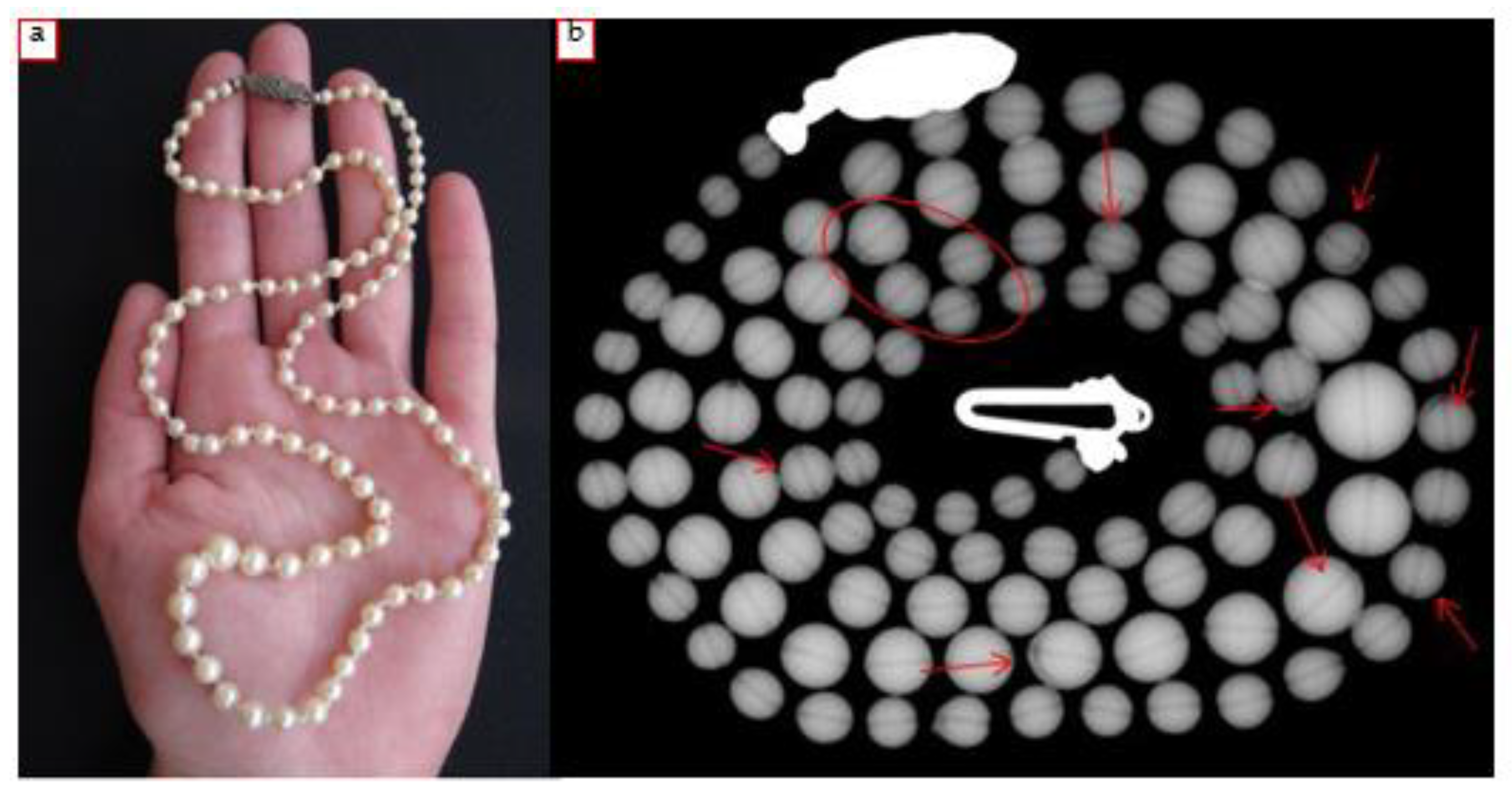
The first analyzed necklace, named for convenience as “necklace 1”, is made up of 98 very small spherical pearls with a white color (Figure 21a). By observing the radiographic image, a spherical cultured nucleus can be seen in almost all pearls (very evident in some cases, less visible in others, Figure 21b); furthermore, the thickness of the nacre is very variable and sometimes a more abundant deposition of conchiolin is observed on the inner core. Some pearls do not show particular recognizable structures: a certain attribution in these cases is not possible, but in general it can be said that most of the pearls that make up the necklace are cultured with a rigid mother-of-pearl core.
The second sample (necklace 2) is a string made up of 57 perfectly spherical pearls, larger than the previous ones (Figure 22a). The radiography allowed us to identify the cultivation nuclei of some pearls, while for most of them a certain attribution is not possible, as no internal structure is clearly observable.
The third sample (necklace 3), from a private collection, is made up of 60 pearls with a perfectly spherical shape and a cream color. In this case, the result of the radiographic investigation showed dark spots, transparent to X-rays, with a circular shape and irregular dimensions, unevenly distributed in the volume of the pearls (Figure 22b). Furthermore, no characteristic structure attributable to a specific cultivation method was observed. Focusing on the dark circular spots, it was supposed that they could most likely be identifiable with very small air bubbles; in fact, the hypothesis that it could be a necklace of imitation pearls (probably Majorca pearls) was advanced, and that the air bubbles trapped in the homogeneous matrix may be a consequence of the production process (i.e., glass core).
Regarding the two single pearls, the first is a hollow cultured pearl, very similar in size and color to the cultured one with a detached core as described in Section 4.3.2. This sample has a considerable size, a gray color and a large superficial fracture (Figure 23a); thanks to this, it is possible to appreciate the thickness of the inorganic superficial layer (extremely thin). It is assumed that this sample could be comparable to the one with detached nucleus, but that it has lost the core due to the presence of the large hole.
The radiography of the sample (Figure 23c) revealed a huge internal cavity and the rather thin thickness of the nacre.
The latest sample is a case of imitation pearl. Imitation pearls are products that simulate the appearance of natural or cultured pearls without their chemical composition, physical properties and structure [51]. The most common ones are produced starting from glass, plastic or shell spheres covered with a material that imitates the nacre. Other types of imitation pearls consist of thick pieces of mother-of-pearl in various colors; imitations of composite pearls could also be found. Imitation pearls can show a great variability of aspects in radiography. The ones based on polymers are transparent to X-rays; on the contrary, pearls made of solid glass or shells produce an opaque white image without structures; the beads made of hollow glass, on the other hand, give a characteristic image consisting of a thin radiopaque border surrounded by a large central cavity transparent to X-rays [52].
The sample analyzed in this work was provided by the R.A.G. gemological laboratory as an imitation pearl and it was decided to carry out only the radiographic investigation. It is a small pearl with a spherical shape and a cream color (Figure 23b).
From the observation of the DR, no element that could lead to a classification as a cultured pearl can be observed, much less as a natural pearl: no details that suggest the presence of epithelial tissue, cultivation nucleus or growth structure are seen (Figure 23d). The entire volume of the pearl is also very homogeneous and opaque to X-rays. Therefore, based on the considerations made above and on the direct observations of the radiography, we can classify this sample as an imitation pearl, made with a shell or in full glass.

5. Conclusions

The main objective of the project illustrated in this work was to develop an investigation methodology for the micro-tomographic analysis of pearls. In the gemological field, and in particular for pearls, it is important to be able to identify the different typology and to distinguish natural pearls from cultured ones. The DR and the micro-CT are very useful tools for this purpose, as they allow us to characterize the examined samples in a non-invasive way, thanks to the visualization of their internal conformation. While the distinction between natural and beaded cultured pearls is generally quite easy, since the inner core is rather easily recognizable using X-rays, distinguishing natural from non-beaded cultured pearls is often difficult and there are often problems in reaching a certain identification of the gems. It is thus necessary to carefully study the details emerging from radiographic and tomographic analysis, focusing on some fine details which, if present, can lead to a specific attribution.
A proper tomographic procedure for the analysis of pearls has been developed for the setup installed in the laboratory of the Physics Department of the University of Torino. The same protocol can be easily adapted to other setups.
The investigations carried out allowed us to establish the origin of the analyzed pearls (natural or cultured), to confirm or deny prior hypotheses, if present, and to highlight also the cultivation methodology used case by case. Furthermore, the examination of a few specific samples showed how large and varied today’s market for cultured pearls is and how difficult, in some cases, the attribution to a certain category is.
Surely, the identification of a pearl’s nature requires a considerable experience in the field; however, in the most particular cases and with the absence of standard parameters, it is not always sufficient to give a correct interpretation to the internal structures. This paper confirms the potentiality and importance of X-ray imaging techniques applied to the study of pearls and underlines how μ-CT has excellent potential for application to this kind of samples.
A prospective future work could be the investigation of the entire volume of some samples using a detector with a larger area, allowing also the quantitative analysis of some features, according to the gemologist research needs. Especially for the samples on which more questions have been raised, this will increase the amount of information obtained from the analysis and, therefore, might allow us to reach a definitive answer on their origin.

Author Contributions

Conceptualization, A.R., D.A., R.N., A.L.G.; Methodology, A.R., A.L.G., D.A., E.C.; Software, A.R., A.L.G.; Validation, A.R, A.L.G., D.A., E.C.; Formal analysis, E.C., A.R.; Investigation, E.C., A.R., D.A.; Resources, R.N.; Data curation, E.C., L.V.; Writing—original draft preparation, L.V., E.C.; Writing—review and editing, L.V., E.C., D.A., A.R., A.L.G., R.N., L.G., S.G.; Visualization, E.C., A.R.; supervision, A.R., A.L.G., S.G.; Project administration, A.R., D.A., R.N.; Funding acquisition, A.L.G. All authors have read and agreed to the published version of the manuscript.

Funding

This research received no external funding.

Acknowledgments

The neu_ART project funded by Regione Piemonte and the INFN CHNet network are warmly acknowledged. The authors wish to thank Cambi Casa d’Aste for having made available a few of the samples considered in the study.

Conflicts of Interest

The authors declare no conflict of interest.

References

  1. Lang, J.; Middleton, A.A. Radiography of Cultural Material, 2nd ed.; Elsevier Butterworth-Heinemann: Oxford, UK, 2005. [Google Scholar]
  2. Casali, F. X-ray and Neutron Digital Radiography and Computed Tomography for Cultural Heritage Physical Techniques in the Study of Art, Archaeology and Cultural Heritage; Bradley, D., Creagh, D., Eds.; Elsevier: Amsterdam, The Netherlands, 2006; pp. 41–123. [Google Scholar]
  3. Morigi, M.P.; Casali, F.; Bettuzzi, M.; Brancaccio, R.; D’Errico, V. Application of X-ray Computed Tomography to Cultural Heritage diagnostics. Appl. Phys. A 2010, 100, 653–661. [Google Scholar] [CrossRef]
  4. Casali, F.; Bettuzzi, M.; Brancaccio, R.; Cornacchia, S.; Giordano, M.; Morigi, M.P.; Pasini, A.; Romani, D.; Talarico, F. Development of High Resolution X-ray DR and CT Systems for Non-Medical Applications, 2003 DGZfP-Proceedings BB 84-CD. In Proceedings of the International Symposium on Computed Tomography and Image Processing for Industrial Radiology, Berlin, Germany, 23–25 June 2003. [Google Scholar]
  5. Re, A.; Albertin, F.; Bortolin, C.; Brancaccio, R.; Buscaglia, P.; Corsi, J.; Cotto, G.; Dughera, G.; Durisi, E.; Ferrarese, W.; et al. Results of the Italian neu_ART project. IOP Conf. Ser. Mater. Sci. Eng. 2012, 37, 012007. [Google Scholar] [CrossRef] [Green Version]
  6. Nervo, M. Il Progetto Neu_ART. Studi e Applicazioni/Neutron and X-ray Tomography and Imaging for Cultural Heritage, Cronache 4, Editris, Torino, 2013. Available online: https://www.centrorestaurovenaria.it/documentazione/pubblicazioni (accessed on 22 November 2021).
  7. Re, A.; Lo Giudice, A.; Nervo, M.; Buscaglia, P.; Luciani, P.; Borla, M.; Greco, C. The Importance of Tomography Studying Wooden Artefacts: A Comparison with Radiography in the Case of a Coffin lid from ancient Egypt. Int. J. Conserv. Sci. 2016, 7, 935–944. [Google Scholar]
  8. Lo Giudice, A.; Corsi, J.; Cotto, G.; Mila, G.; Re, A.; Ricci, C.; Sacchi, R.; Visca, L.; Zamprotta, L. A New Digital Radiography System for Paintings on Canvas and on Wooden Panels of Large Dimensions. In Proceedings of the 2017 IEEE International Instrumentation and Measurement Technology Conference (I2MTC 2017), Torino, Italy, 22–25 May 2017. [Google Scholar]
  9. Re, A.; Albertin, F.; Avataneo, C.; Brancaccio, R.; Corsi, J.; Cotto, G.; De Blasi, S.; Dughera, G.; Durisi, E.; Ferrarese, W.; et al. X-ray Tomography of Large Wooden Artworks: The Case Study of “Doppio Corpo” by Pietro Piffetti. Herit. Sci. 2014, 2, 19. [Google Scholar] [CrossRef] [Green Version]
  10. Re, A.; Corsi, J.; Demmelbauer, M.; Martini, M.; Mila, G.; Ricci, C. X-ray Tomography of a Soil Block: A Useful Tool for the Restoration of Archaeological Finds. Herit. Sci. 2015, 3, 4. [Google Scholar] [CrossRef] [Green Version]
  11. Vigorelli, L.; Re, A.; Guidorzi, L.; Cavaleri, T.; Buscaglia, P.; Nervo, M.; Facchetti, F.; Borla, M.; Grassini, S.; Lo Giudice, A. X-ray Imaging Investigation and Study on the Gilding Technique of an Ancient Egyptian Taweret’s Wooden Statuette. J. Imaging 2021, 7, 229. [Google Scholar] [CrossRef]
  12. Vigorelli, L.; Lo Giudice, A.; Cavaleri, T.; Buscaglia, P.; Nervo, P.; Del Vesco, P.; Borla, M.; Grassini, S. Upgrade of the X-ray Imaging Set-up at CCR “La Venaria Reale”: The Case Study of an Egyptian Wooden Statuette. In Proceedings of the 2020 IMEKO TC-4 International Conference on Metrology for Archaeology and Cultural Heritage, Trento, Italy, 22–24 October 2020. [Google Scholar]
  13. Read, P.G. Gemmology, 3rd ed.; Elsevier: Amsterdam, The Netherlands, 2005; pp. 223–235. [Google Scholar]
  14. Sturman, N. The Microradiographic Structures of Non-Bead Cultured Pearls; GIA Lab. Notes; GIA Thailand: Bangkok, Thailand, 2009. [Google Scholar]
  15. Soldati, A.L.; Jacob, D.E.; Wehrmeister, U.; Hofmeister, W. Structural Characterization and Chemical Composition of Aragonite and Vaterite in Freshwater Cultured Pearls. Miner. Mag. 2008, 72, 579–592. [Google Scholar] [CrossRef]
  16. Gutmannsbauer, W.; Hänni, H. Structural and Chemical Investigations on Shells and Pearls of Nacre Forming Salt- and Fresh-Water Bivalve Molluscs. J. Gemmol. 1994, 24, 241–252. [Google Scholar] [CrossRef]
  17. Anderson, B.W. The Use of X Rays in the Study of Pearls. Br. J. Radiol. 1932, 5, 57–64. [Google Scholar] [CrossRef]
  18. Krzemnicki, M.S.; Friess, S.D.; Chalus, P.; Hänni, H.A.; Karampelas, S. X-Ray Computed Microtomography: Distinguishing Natural Pearls from Beaded and Non-Beaded Cultured Pearls. Gems Gemol. 2010, 46, 128–134. [Google Scholar] [CrossRef]
  19. Krzemnicki, M.S. Micro X-ray Tomography of Pearls: SSEF Introduces a New Service for Pearl Testing. SSEF Facet. 2010, 17, 9–10. [Google Scholar]
  20. Rosc, J.; Hammer, V.; Brunner, R. X-ray Computed Tomography for Fast and Non-Destructive Multiple Pearl Inspection. Case Stud. Nondestruct. Test. Eval. 2016, 6, 32–37. [Google Scholar] [CrossRef] [Green Version]
  21. Wehrmeister, U.; Goetz, H.; Jacob, D.; Soldati, A.; Xu, W.; Duschner, H.; Hofmeister, W. Visualization of the Internal Structures of Cultured Pearls by Computerized X-ray Microtomography. J. Gemmol. 2008, 31, 15–21. [Google Scholar] [CrossRef]
  22. Stiles, K.A.; Stiles, N.R.; Stiles, N.R. The Pearl, a Biological Gem. Bios 1943, 14, 69–80. [Google Scholar]
  23. Southgate, P.C.; Lucas, J.S. The Pearl Oyster, 1st ed.; Elsevier: Oxford, UK, 2008. [Google Scholar]
  24. Hänni, H.A. A Short Synopsis of Pearls: Natural, Cultured, Imitation. J. Gemmol. Assoc. Hong Kong 1995, 18, 43–46. [Google Scholar]
  25. Scarratt, K.; Bracher, P.; Bracher, M.; Attawi, A.; Safar, A.; Saeseaw, S.; Homkrajae, A.; Sturman, N. Natural Pearls from Australian Pinctada Maxima. Gems Gemol. 2012, 48, 236–261. [Google Scholar] [CrossRef] [Green Version]
  26. Hänni, H.A. Natural Pearls and Cultured Pearls: A Basic Concept and Its Variations. Aust. Gemmol. 2012, 24, 258–266. [Google Scholar]
  27. Nagai, K. A History of the Cultured Pearl Industry. Zool. Sci. 2013, 30, 783–793. [Google Scholar] [CrossRef] [PubMed] [Green Version]
  28. Alagarswami, K. Technology of Cultured Pearl Production. CMFRI Bull. Pearl Cult. 1987, 39, 98–106. [Google Scholar]
  29. Cartier, L.; Krzemnicki, M.S. New Developments in Cultured Pearl Production: Use of Organic and Baroque Shell Nuclei. Aust. Gemmol. 2013, 25, 6–13. [Google Scholar]
  30. Sturman, N.; Strack, E. “Soufflé” Freshwater Cultured Pearls. Gems Gemol. 2010, 46, 58–72. [Google Scholar]
  31. Available online: https://www.ignroma.it/wp-content/uploads/2014/05/IGN-Roma-MicroComputedTomography.pdf (accessed on 12 September 2021).
  32. Sturman, N.; Al-Attawi, A. The “Keshi” Pearl Issue. Gems Gemol. 2006, 42, 142. [Google Scholar]
  33. Haws, M.C.; Ellis, S.C.; Ellis, E.P. Producing Half-Pearls (Mabe); Western Indian Ocean Marine Science Assocaition: Zanzibar, Tanzania, 2006; p. 17. [Google Scholar]
  34. Re, A.; Angelici, D.; Boano, R.; Bortolin, C.; Brancaccio, R.; Corsi, J.; Fantino, F.; Grassi, N.; Lo Giudice, A.; Mila, J.; et al. Use of a Versatile Instrument for X-ray Radiography and Tomography of Artworks, Precious Objects and Archaeological Materials. In Proceedings of the FisMat 2013—Italian National Conference on Condensed Matter Physics, Milan, Italy, 9–13 September 2013; pp. 143–144. [Google Scholar]
  35. Vigorelli, L.; Re, A.; Guidorzi, L.; Brancaccio, R.; Bortolin, C.; Grassi, N.; Mila, G.; Pastrone, N.; Sacchi, R.; Grassini, S.; et al. The Study of Ancient Archaeological Finds through X-ray Tomography: The Case of the “Tintinnabulum” from the Museum of Anthropology and Ethnography of Torino. In Proceedings of the 2021 IEEE International Conference on Metrology for Archaeology and Cultural Heritage, Milan, Italy, 20–22 October 2020. [Google Scholar]
  36. Kak, A.C.; Slaney, M. Principles of Computerized Tomographic Imaging; Cotellessa, R.F., Ed.; IEEE Press: Hoboken, NJ, USA, 1987; Chapter 3; pp. 49–112. [Google Scholar]
  37. Brancaccio, R.; Bettuzzi, M.; Casali, F.; Morigi, M.P.; Levi, G.; Gallo, A.; Marchetti, G.; Schneberk, D. Real-Time Reconstruction for 3-D CT Applied to Large Objects of Cultural Heritage IEEE Trans. Nucl. Sci. 2011, 58, 1864–1871. [Google Scholar] [CrossRef]
  38. Martz, H.E.; Shull, P.J.; Schneberk, D.J.; Logan, C.M. X-ray Imaging; CRC Press Inc.: Boca Raton, FL, USA, 2009. Available online: http://www.llnl.gov (accessed on 22 November 2021).
  39. Barret, J.F.; Keat, N. Artifacts in CT: Recognition and Avoidance. Radiographics 2004, 24, 1679–1691. [Google Scholar] [CrossRef]
  40. Kijewski, P.K.; Bjärngard, B.E. Correction for Beam Hardening in Computed Tomography. Med. Phys. 1978, 5, 209–214. [Google Scholar] [CrossRef]
  41. Meganck, J.A.; Kozloff, K.M.; Thornton, M.M.; Broski, S.M.; Goldstein, S.A. Beam Hardening Artifacts in Micro-Computed Tomography Scanning Can Be Reduced by X-ray Beam Filtration and the Resulting Images Can Be Used to Accurately Measure BMD. Bone 2009, 45, 1104–1116. [Google Scholar] [CrossRef] [PubMed] [Green Version]
  42. Bond, K.P.; Schneberk, D.J. Lawrence Livermore National Laboratory, Imgrec Manual, Technical Reports, 2012. Available online: http://www.llnl.gov.www.gia.edu (accessed on 22 November 2021).
  43. Goebel, M.; Dirlam, D.M. Polynesian Black Pearls. Gems Gemol. 1989, 25, 130–148. [Google Scholar] [CrossRef]
  44. Kim, Y.; Choi, H.; Lee, B.; Abduriyim, A. Identification of Irradiated South Sea Cultured Pearls Using Electron Spin Resonance Spectroscopy. Gems Gemol. 2012, 48, 292–299. [Google Scholar] [CrossRef]
  45. Park, R.Y.; Kim, P.C. The Cultivation and Characterization of Akoya Pearls. J. Korean Cryst. Growth Cryst. Technol. 2005, 15, 152–156. [Google Scholar]
  46. Akamatsu, S.; Zansheng, L.T.; Moses, T.M.; Scarratt, K. The Current Status of Chinese Freshwater Cultured Pearls. Gems Gemol. 2001, 37, 96–113. [Google Scholar] [CrossRef] [Green Version]
  47. Scarratt, K.; Moses, T.M.; Akamatsu, S. Characteristics of Nuclei in Chinese Freshwater Cultured Pearls. Gems Gemol. 2000, 36, 98–109. [Google Scholar] [CrossRef]
  48. Otter, L.M.; Wehrmeister, U.; Enzmann, F.; Wolf, M.; Jacob, D. A Look inside a Remarkably Large Beaded South Sea Cultured Pearl. Gems Gemol. 2014, 50. [Google Scholar] [CrossRef]
  49. Gordona, S.E.; Ana’Akau’olac, S.; Wingfieldd, M.; Kishored, P.; Southgated, P.C. Using Microradiography to Assess Nacre Thickness of Mabé Pearls: Technique Suitability and Insights. Aquaculture 2018, 492, 195–200. [Google Scholar] [CrossRef]
  50. CIBJO. The Pearl Book: Natural, Cultured, Composite & Imitation Pearls—Terminology & Classification; CIBJO: Bern, Switzerland, 2014. [Google Scholar]
  51. Zhou, J.Y.; Zhou, C. Shell Pearls as a Pearl imitation. Gems Gemol. 2014, 374, 50. [Google Scholar]
  52. O’Donoghue, M. Gems: Their Sources, Descriptions and Identification, 6th ed.; Elsevier: Oxford, UK, 2006; pp. 556–625. [Google Scholar]
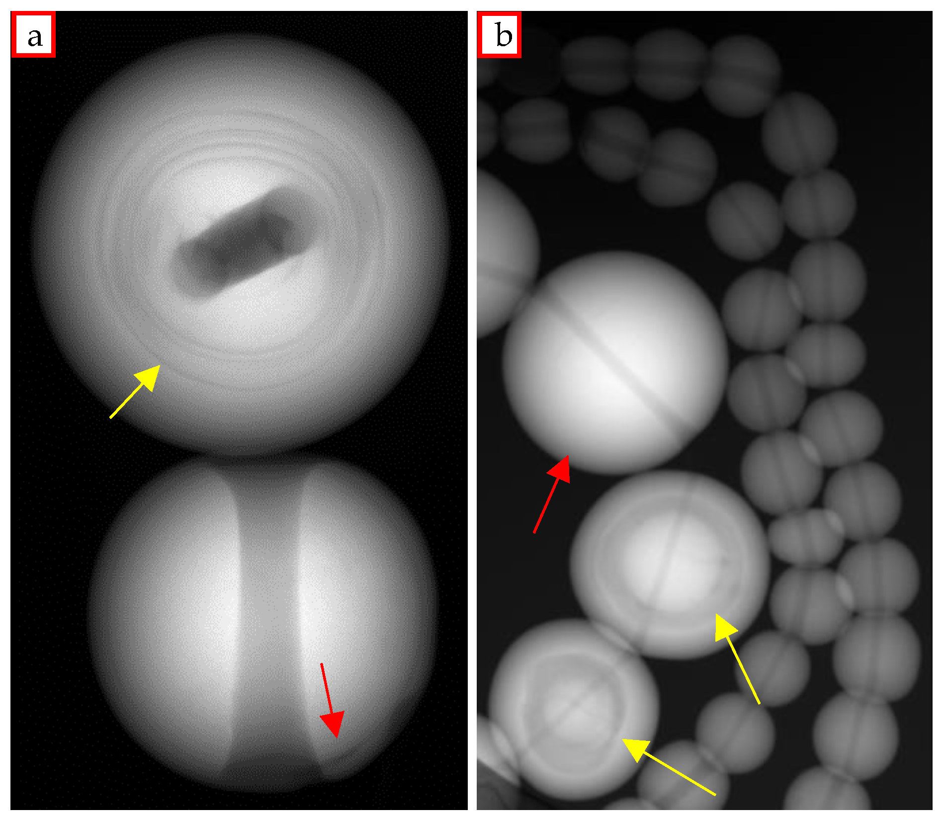
Figure 1. Radiographic images of (a) natural pearl and beaded cultured pearl and (b) a detail of a necklace in which both natural and cultured pearls could be distinguish (yellow arrows: alternated aragonite and conchiolin layers, characteristic of natural pearls; red arrows: organic layer typical of cultivated pearls).
Condensedmatter 06 00051 g001
Figure 2. Tomographic set-up used for the analysis: (a) X-ray source in front of the rotation platform and (b) top view of the entire set-up (1: X-ray source; 2: sample on the rotating platform; 3: X-ray linear detector).
Condensedmatter 06 00051 g002
Figure 3. Tomographic slices of a pearl and relative profile along the red lines obtained (a) without and (b) with the 2 mm thick Al filter in front of the X-ray source.
Condensedmatter 06 00051 g003
Figure 4. Tomographic slices of a pearl (a) without ring artifact correction (red arrow indicates the concentric rings) and (b) with the LLNL software correction (using the “Ringo” routine [42]).
Condensedmatter 06 00051 g004
Figure 5. Results of the earrings (a) analysis: radiographic image (b) and CT slices of the earring A (c) and B (d), where the classic internal “onion” structure of natural pearls can be seen.
Condensedmatter 06 00051 g005
Figure 6. Results of the brooch pearl (a) analysis: radiographic image (b), 3D model of the section analyzed (c) and CT slice (d), where the particular internal structure is clearly visible.
Condensedmatter 06 00051 g006
Figure 7. Results of the South Sea pearl (1.35 cm) (a) analysis: radiographic image (b), where the red arrows indicate the nacre thickness, and CT slice (c), where the red arrow indicates the organic layer of deposited conchiolin.
Condensedmatter 06 00051 g007
Figure 8. Results of the irradiated pearl (a) analysis: radiographic image (b) and CT slice (c), where the organic conchiolin layer is visible, more abundant in the lower part (red arrows).
Condensedmatter 06 00051 g008
Figure 9. Results of the pink pearl (a) analysis: radiographic image (b) and CT slice (c), where the organic conchiolin layer is visible (red arrow).
Condensedmatter 06 00051 g009
Figure 10. Results of the black pearl (a, double view of the sample) analysis: radiographic image (b) and CT slice (c), the organic conchiolin layer is indicated by the red arrow.
Condensedmatter 06 00051 g010
Figure 11. Results of the Akoya pearl (a) analysis: radiographic image (b) and CT slice (c), the conchiolin is indicated by the red arrow.
Condensedmatter 06 00051 g011
Figure 12. Results of three freshwater pearl (a) analysis: radiographic images of pearl 2 on the left and pearl 1 on the right (b) and CT slices (c), respectively of pearl 1, 2 and 3 (red arrow: the characteristic “moustache” of pearl 2).
Condensedmatter 06 00051 g012
Figure 13. Results of the Chinese pearl (a) analysis: radiographic image (b), from which the innested tissue is evident (red circle and arrows), a CT slice (c) and the 3D model (d), with the segmented organic material (red portion, corresponding to the dark spot in the yellow circle).
Condensedmatter 06 00051 g013
Figure 14. Results of the Keshi pearls (a: certain Keshi sample; d: Keshi A and B samples) analysis: radiographic images of certain Keshi (b), Keshi A (e) and Keshi B (f); CT slices of the certain Keshi (c), Keshi A (e) and Keshi B (f). The typical “moustache” is point by red arrows in both radiographic and tomographic images.
Condensedmatter 06 00051 g014
Figure 15. Results of the Soufflè pearl (a, analyzed sample on the top image and a different sample, already cut, on the bottom image) analysis: radiographic image (b) and CT slice (c) (red arrows: organic layer around the cavity).
Condensedmatter 06 00051 g015
Figure 16. Results of the pearl with the detached core (a) analysis: radiographic image (b), a CT slice (c) and the 3D model obtained (d) (red arrows: organic layer of conchiolin; red circle: thin area of the pearl surface).
Condensedmatter 06 00051 g016
Figure 17. Results of the Mabè pearl (a) analysis: radiographic image (b), a CT slice (c) and the 3D model obtained (d), where the red arrows indicate the empty space due probably to the production processes.
Condensedmatter 06 00051 g017
Figure 18. Results of the baroque pearl (a) analysis: radiographic image (b) and a CT slice (c) where some darker spots are visible, that represent the cultivation implanted tissue (red arrows).
Condensedmatter 06 00051 g018
Figure 19. Results of the white pearl (a,b) analysis: radiographic image (c) a CT slice (d) where only a small darker area is visible near the center hole (red circles), and the 3D model (e) from which the shape of the possible organic material implanted for cultivation was obtained.
Condensedmatter 06 00051 g019
Figure 20. Results of the “Shell pearls” earrings (a) analysis: radiographic image (b) and a CT slice (c) where an inner fracture is visible (red arrow).
Condensedmatter 06 00051 g020
Figure 21. The “necklace 1” (a) and the resulting radiographic image (b), where the red arrows indicate the beaded cultured pearls.
Condensedmatter 06 00051 g021
Figure 22. Radiography of the “necklace 2” (a, red arrow: beaded cultured pearls) and “necklace 3” (b), for which some dark spot in some of the pearls are highlighted (indicated by red arrows, probably air bubble associated with the production process).
Condensedmatter 06 00051 g022
Figure 23. The two single particular pearls, the empty one (a) and the imitation case (b), and the relative radiographic images, (c) of the former and (d) of the latter.
Condensedmatter 06 00051 g023
Table 1. Optimized parameters for the CT analysis of the pearls sample.
Optimized Analysis Parameters
Tube voltage90 kV
Tube current110 µA
Al filter2 mm
Focal spot7 µm
Source-detector distance (SDD)425 mm
Object-detector distance (ODD)367 mm
Source-object distance (SOD)58 mm
Magnification7.3×
Penumbra ⁽ᵃ⁾44 µm
Voxel size6.6 µm
Angular step0.25°
N° of projection1440
Integration time1792 ms
Investigated area30.2 × 0.8 mm
Time for a complete acquisition96 min
⁽ᵃ⁾ Penumbra effect is the blurring at the edges of the object image, mainly due to the focal spot size and the adopted distances [1] (pp. 14–18).
Publisher’s Note: MDPI stays neutral with regard to jurisdictional claims in published maps and institutional affiliations.