Article

Synthesis of PTh/PEDOT Films into FTO Substrate by Electrodeposition, for Energy Storage Systems

by
Daniel Alejandro Vázquez-Loredo
,
Ulises Páramo-García
*,
Luis Alejandro Macclesh Del Pino-Pérez
,
Nohra Violeta Gallardo-Rivas
,
Ricardo García-Alamilla
and
Diana Lucia Campa-Guevara
Tecnológico Nacional de México/I. T. Cd. Madero, Centro de Investigación en Petroquímica, Prol. Bahía de Aldahir y Av. De las Bahías, Parque de la Pequeña y Mediana Industria, Altamira 89600, Tamaulipas, Mexico
*
Author to whom correspondence should be addressed.
Condens. Matter 2025, 10(2), 26; https://doi.org/10.3390/condmat10020026
Submission received: 31 March 2025 / Revised: 17 April 2025 / Accepted: 25 April 2025 / Published: 27 April 2025
(This article belongs to the Section Surface and Interfaces)

Abstract

:
Thin films of monomeric species polythiophene (PTh), poly-(3,4-ethylenedioxythiophene) (PEDOT), and the copolymer PTh/PEDOT were prepared through electropolymerization and deposited above fluorine-doped tin oxide (FTO) substrates. The functional groups of the monomeric species (PTh, PEDOT) and polymeric species (PTh/PEDOT) were characterized by Fourier-transform infrared spectroscopy, while morphological properties were evaluated using scanning electron microscopy, optical microscopy, and atomic force microscopy. The analysis showed that monomers films exhibited less material deposition; otherwise, the copolymer PTh/PEDOT showed better deposition on substrate. In addition, the electrochemical characterization showed that the materials that resulted from copolymerization presented an improvement in electrochemical properties relating to monomer properties. The effect of overoxidation of the monomers applied during the electropolymerization process is also known.

1. Introduction

New legislation concerning environmental issues aims to reduce the use of fossil fuels in the upcoming years [1,2]. In addition to the current electronic devices in consumption (cell phones, laptops, tablets, etc.), more efficient, lightweight, and secure energy storage systems are required. There is currently a race in the development of materials for energy storage, including conductive polymers (CPs). These CPs and their counterparts have been and continue to be extensively studied due to their properties that allow current conduction, as well as the inherent characteristics of a polymer (flexibility, low weight, corrosion resistance, etc.) [3,4]. Some of these conductive polymers possess functional groups, such as nitrogen, sulfur, and oxygen (N, S, and O), that can interact effectively with lithium polysulfide atoms, enabling their widespread use in the field of lithium–sulfur (Li-S) and lithium–selenium (Li-Se) batteries [5,6,7]. CPs are attractive for incorporation into high-performance energy storage system components (capacitors and rechargeable batteries). Currently, the most relevant conductive polymers for use in these system component due to their ease of synthesis and high electrical conductivity are PPy (polypyrrole), PTh, PEDOT, PProDOT (poly(3,4-propylenedioxythiophene)), PANI (polyaniline), and PEDOT:PSS (poly(styrene sulfonate) [8,9]. One of the most important functions of conductive polymers in Li-S/Se batteries is to act as sulfur carriers, redox mediators, coatings (cathode or separator coatings), interlayers, and layers to improve cathode conductivity. They are also implemented to reduce volume expansion and inhibit the dissolution of lithium polysulfides [10,11,12,13].
Among CPs, materials such as polythiophene (PTh) possess unique qualities, such as high environmental resistance, good electrical conductivity, and other properties, making them suitable candidates for use as coatings [14]. Likewise, PANI and PPy have been studied for various practical applications, such as sensors [15], photocatalytic activity [16], etc. However, PTh has demonstrated more applications in the degradation of dyes and electrode coatings [17,18]. In particular, PTh has been employed in sensors and anti-static coatings due to its adjustable conductivity. This adjustability arises from the presence of an extended π-bonding system in its macrostructure, and the conductivity can be controlled through doping with “n-type” or “p-type” impurities [19,20]. The properties exhibited by PTh that make it suitable for lithium-ion batteries include high energy density, faster charge–discharge processes, and high energy storage capacity [21].
Different studies have demonstrated that the copolymerization of CPs (conductive polymers) can enhance their properties, whether by improving their conductivity, redox, or oxidative capacity. This is essential because PTh, as an anode material for lithium batteries, exhibits reversibility in its redox behavior. However, due to its low redox activity, its appropriate structural design can improve the transfer of lithium ions [22,23].
Ustamehmetoğlu et al. [24] carried out the copolymerization of benzothiophene and thiophene using a potentiodynamic method. They also polymerized individual monomers along with polypyrrole for comparison. Based on the results obtained from the synthesis of polymers and copolymers, they concluded that the parameters for copolymerization were similar to those for individual polymerization. However, each material obtained exhibited different physicochemical properties. One material with interesting properties for copolymer development is PEDOT. As a conductive polymer, it has attracted attention due to its great stability, low oxidation potential, and high stability in its oxidized form [25].
Seung Hwa Lee et al. [26] synthesized a copolymeric nanocomplex of PTh/PEDOT through a two-step polymerization of 3,4-ethylenedioxythiophene (EDOT) in the presence of PTh. They demonstrated that this copolymer exhibited good conductivity in relation to the charge of PEDOT, reaching up to 475 S/cm. Furthermore, it showed an improvement in the Seebeck effect, a fundamental characteristic for thermoelectric systems.
In this work, synthesis was carried out through electropolymerization of EDOT via a propagation mechanism involving radical formation (irreversible monomer oxidation). This polymerization starts in solution and proceeds from the oxidation of a dissolved tetramer and so on until the deposition of long chains for the formation of the respective polymer [27,28,29]. The first potential window of −0.2 V to 1.2 V vs. Ag/AgCl was used to obtain the copolymer, generating conditions for homopolymers of PTh and PEDOT. When comparing the electrochemical response of the copolymer with the homopolymer, appreciable differences were observed in the area under the curve, which is related to the amount of material deposited onto the working substrate.

2. Results and Discussion

2.1. Electrosynthesis

The PTh/PEDOT synthesized within the potential window of −0.2 V to 1.4 V vs. Ag/AgCl exhibited a maximum generated current of 5.5 mA. Moreover, an increase in the capacitive effect and a larger material deposit were observed in line with the greater area under the curve (Figure 1). The polymerization voltammograms (Figure 1) reveal that the PTh/PEDOT system generates a maximum current of 6.1 mA when the potential window is extended to 1.6 V vs. Ag/AgCl, surpassing the individual homopolymers (PTh: 5.3 mA; PEDOT: 5.4 mA). This enhancement suggests a synergistic interaction between monomers during electropolymerization, as joint oxidation promotes the formation of hybrid chains [27]. Additionally, the current integral (area under the curve) is significantly larger for the copolymer, indicating greater material deposition attributable to the stability of intermediate radicals in the combined system [28,29].
For the last electrosynthesis condition, applying a potential window of −0.2 V to 1.6 V vs. Ag/AgCl, a more evident overoxidation effect was notable, a response associated with the behavior of PTh. Upon exceeding the potential of −0.2 V to 1.4 V vs. Ag/AgCl, it begins to overoxidize under the same conditions. Consequently, it can be concluded that this response is attributed to PTh, as it overoxidizes upon surpassing the potential where it begins to do so. As result, PTh interferes with the capacitive effect of the copolymer, as well as potentially affecting its structure, the amount of material deposited, stability, adhesion, and composition. The electrical current generated for this system (6.1 mA) is higher than that obtained under the same conditions for the PTh and PEDOT homopolymers (5.30 mA and 5.4 mA, respectively).
The area under the curve changes with respect to the preceding material, exerting little control over the material deposited on the substrate. Capacitive behavior related to the conductivity of the material and a reconfiguration in the polymer chains are observed, altering the alternation of double bonds that allow for the passage of electrons and are related to electrical conductivity.
The cyclic voltammogram of PTh/PEDOT corresponding to the material synthesis in the potential window of −0.2 V to 1.6 V vs. Ag/AgCl reveals the capacitive effect and instability of the material occurring through the overoxidation of PTh within this potential range. However, this particular overoxidation effect depicted in this voltamperogram is unprecedented and has not been reported in the literature consulted so far in this study for the PTh-PEDOT system.
Considering that these are two distinct species, the existence of two different monomer species attributed to the various electrochemical responses obtained in the studies, both using homopolymers and for the copolymer, raises the challenge of identifying whether a composite material or a copolymer is being obtained. Although various authors suggest the presence of a copolymer for this type of system, they do not provide compelling scientific evidence [28,29,30,31,32,33].

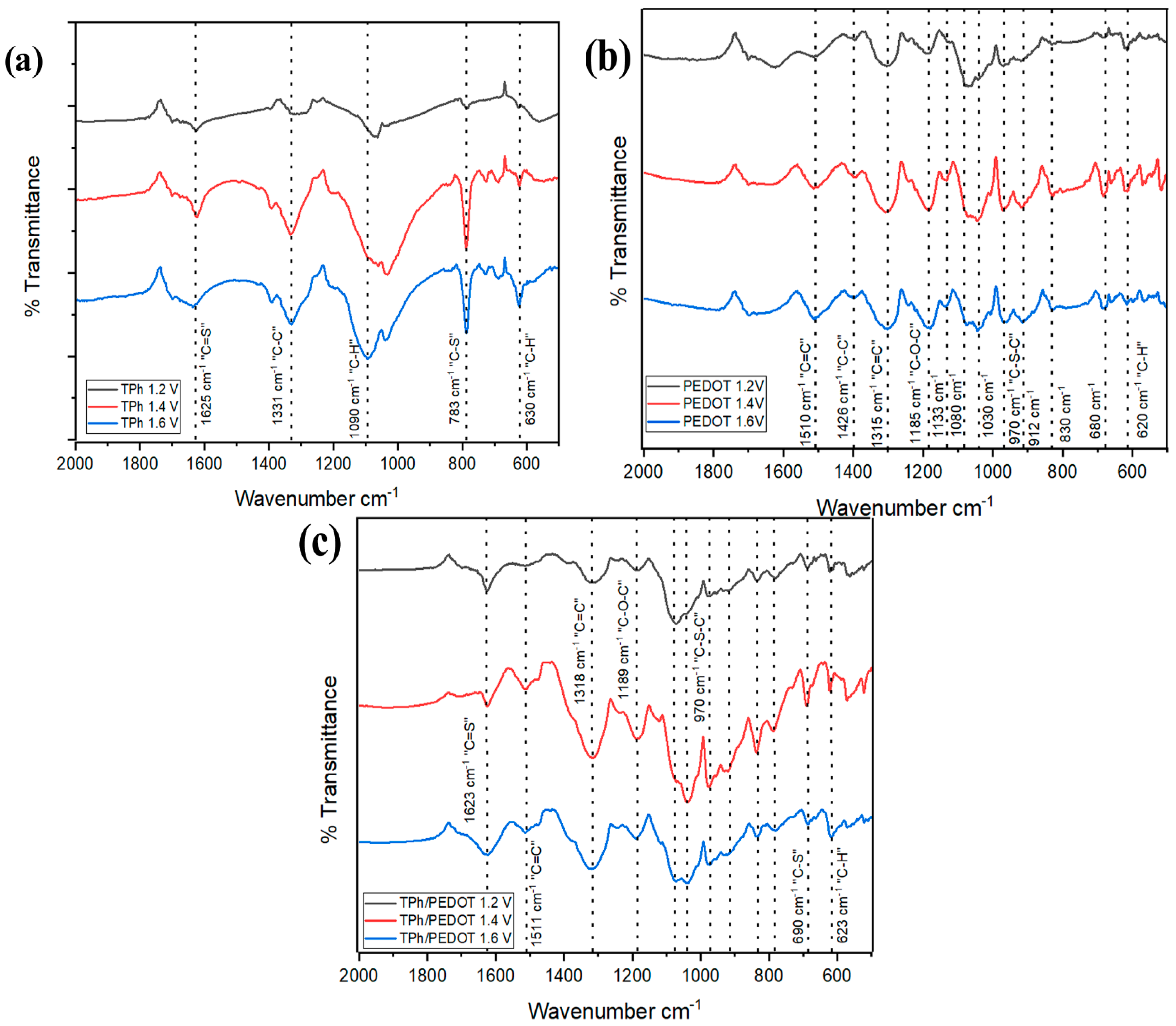
2.2. FTIR Characterization

Figure 2a–c show the characteristic FTIR spectra of the different thin films synthesized on FTO substrates. The high-frequency bands are attributed to the stretching modes of the thiophene ring [34]. Within these signals, the bands at 1376 cm−1 are attributed to symmetric C-C stretching, at 1090 cm−1 to in-plane C-H bending, and at 785 cm−1 to out-of-plane C-H bending features of 2,5-disubstituted thiophene, while the bands at 839 and 693 cm−1 can be attributed to C-S and C-S-C stretching and bending vibrations (in-plane deformation) in PTh. The signals at 848, 1130, 1216, and 1343 cm−1 are characteristic of substrates with a homogeneous PTh coating [35].
In the case of the PEDOT system film, the bands at 970, 912, 830, and 680 cm−1 are characteristic of vibrational stretching of C-S-C bonds. The signals around 1185, 1133, 1080, and 1030 cm−1 are attributed to vibrational bending of C-O-C bonds in the ethylenedioxy group, and around 1426 cm−1 is attributed to C=C stretching vibration [36,37,38,39]. Approximately 1511 and 1315 cm−1 are assigned to the asymmetric stretching modes of C=C bonds and the inter-ring stretching modes of C-C bonds, respectively [40].
Figure 2c shows the spectrum of the PTh/PEDOT material at different potential windows (1.2 to 1. 6 V), observing that the signal located at 1331 cm−1 corresponding to PTh, which identifies the C-C bond of the ring cycle of the thiophene or bithiopene molecule, is joined to the PEDOT signal centered at 1315 cm−1, identified as the signal of the C=C double bond in the film composed of both polymeric species; these signals give rise to a broad and rounded signal located around 1318–1320 cm−1, which increases its intensity when the potential window goes from 1.2 to 1.6 V. On the other hand, the signal of the polythiophene at 783 cm−1 (Figure 2a), whose intensity increases with increasing potential, is significantly reduced in the composite material and moves to 690 cm−1, while the signal at 1623 cm−1, corresponding to C=S, prevails in the composite material. The infrared spectra show that a composite film of PTh and PEDOT was formed, and although the interaction between the two polymeric species cannot be guaranteed, it is possible to observe the growth of both on the surface of the substrate.
In the copolymeric system, the characteristic bands of both species can be observed. It is evident that the optimal potential window for PTh, PEDOT, and PTh/PEDOT is 1.2 V, while at a potential window of 1.6 V, the definition of the peaks decreases along with their intensity. This is due to the fact that at higher potential, the monomers polymerize in the medium. Wolfgang Schuhmann et al. observed this behavior in electrochemical deposition of polymer films on electrodes surfaces [41].

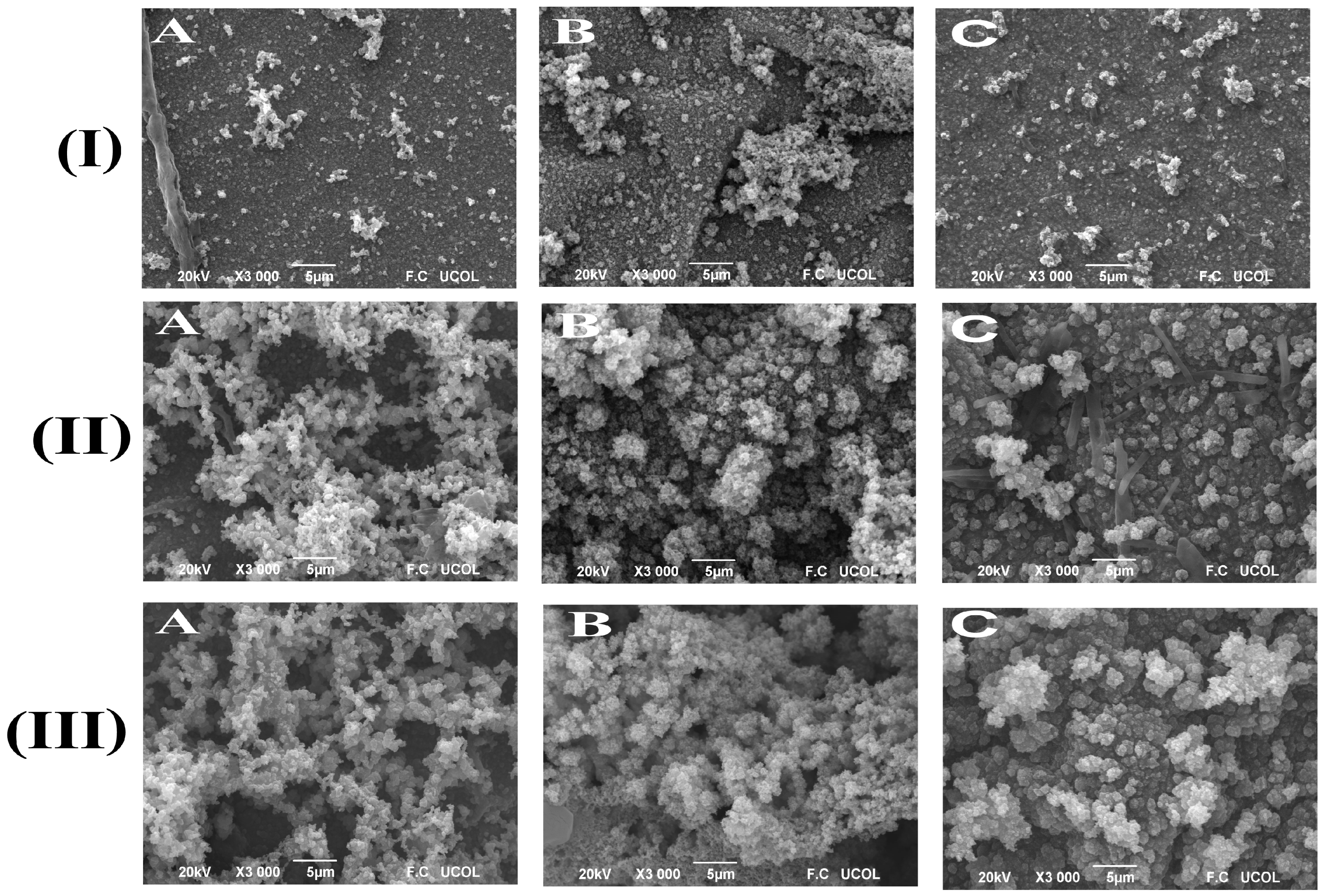
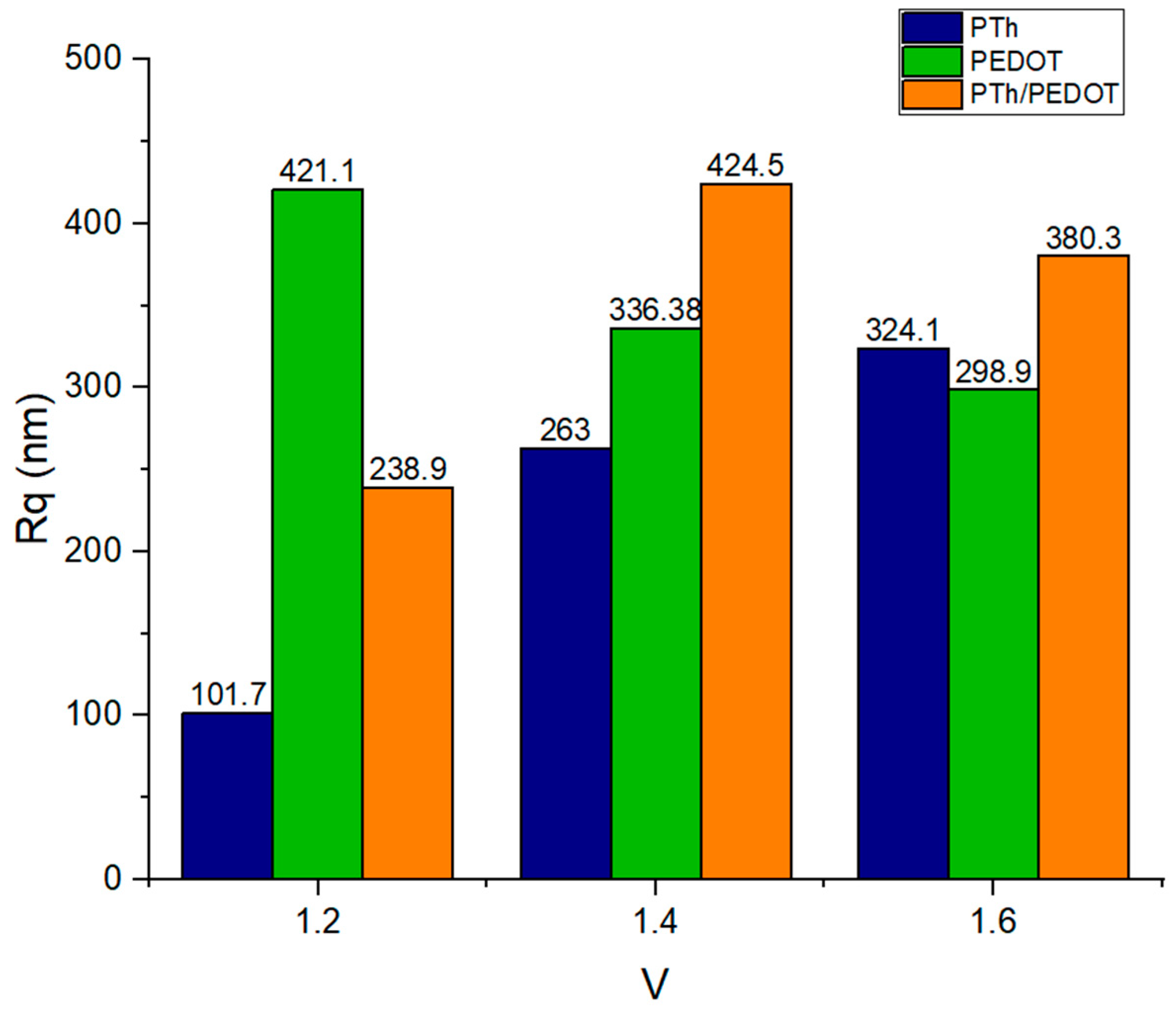
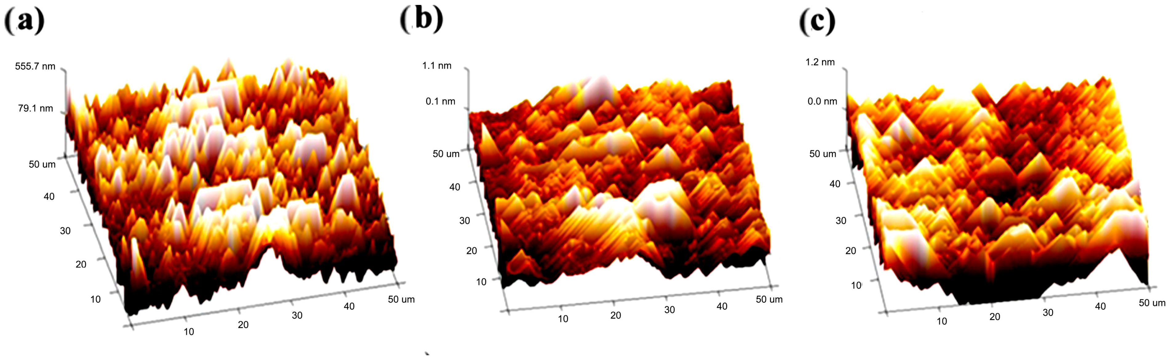
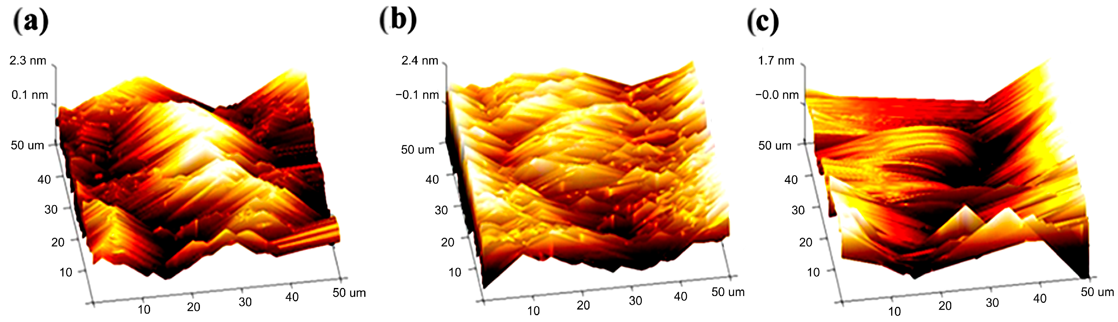
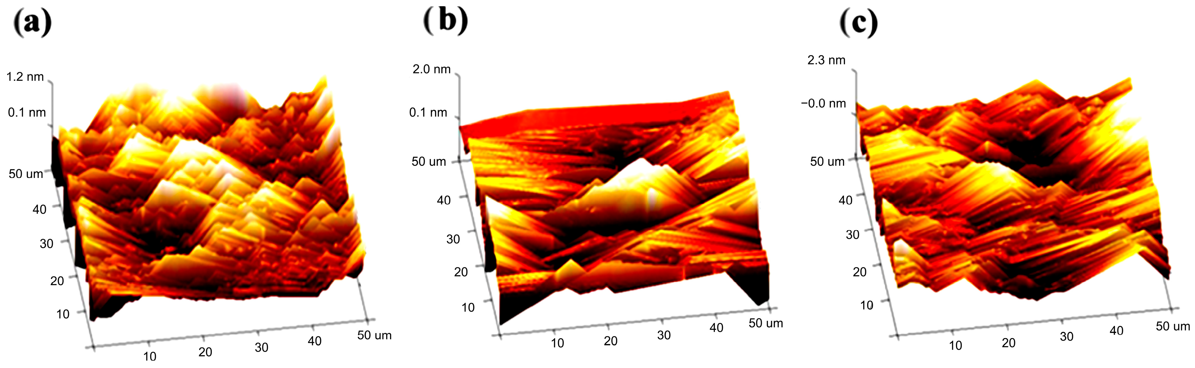
2.3. Morphological Characterization

In Figure 3I, the optical micrographs of the first potential window, ranging from −0.2 V to 1.2 V vs. Ag/AgCl, of PTh and PEDOT show a random deposition that exposes areas on the substrate. This is related to the small area under the curve present in the voltammogram of their synthesis. Both materials exhibited parts of the substrate with slight transparency in areas where a significant amount of material was not deposited. This slight transparency is due to a very thin polymer layer, mainly composed of oligomers, which is a common process [42].
In Figure 3II(A), it is possible to observe the deposition of PTh over the entire surface of the working electrode, covering it entirely, unlike the material synthesized with an oxidation potential in the anodic region of 1.2 V versus Ag/AgCl. In II(B), it is again possible to observe that the material completely covers the substrate surface; however, cracks can be appreciated. In II(C), the micrograph of the copolymer is shown, and like the previous micrographs synthesized in this potential range, it can be observed that it covers the entire substrate surface with a stable arrangement and minimal cracks, confirming the synergy between both copolymeric materials.
In Figure 3III(A), it can be observed that the polymer continues to maintain a uniform and constant electrodeposition without cracks. In III(B), it can be seen that the material was deposited in a very non-uniform manner, possibly due to overoxidation leading to polymerization in the medium and not on the substrate. This phenomenon was previously explained in the characterization by FTIR. In III(C), the uniform and complete electrodeposition along the entire substrate is appreciable.
In Figure 4I(A), the electrodeposition of PTh is observed, showing a thin and uniform layer extending along the substrate, the result of a controlled deposition. In Figure 4I(B), PEDOT synthesized in the potential window of 0.2 V to 1.2 V vs. Ag/AgCl Ag/AgCl (LiClO4/ACN) is observed to contain very large agglomerates in the form of very long rods with cauliflower-shaped particles. The surface appears irregular and completely amorphous. This potential window is where polypyrrole was deposited in smaller quantities; however, there is an evident change and increase in the amount of deposited material compared to its counterpart, both from PTh and PEDOT. The resulting material is very compact, with particle sizes not exceeding two micrometers. This is a positive indication regarding the objective of this study, which aimed to find a synergistic effect by combining two monomers with particular properties.
The copolymer exhibits an optimal potential window (−0.2 V to 1.4 V vs. Ag/AgCl) where deposition is stable and homogeneous (Figure 3II(C)). At higher potentials (1.6 V), the overoxidation of PTh—observed as a current decay—alters the copolymer morphology (Figure 4III(C)), a phenomenon previously reported for thiophene-based systems [43]. However, this effect is less severe than in pure PTh, suggesting that PEDOT stabilizes the polymeric matrix [25].
In Figure 4II(A), the micrograph of PTh is presented, showing a surface with a porous appearance, where aggregates begin to cover the substrate surface with cauliflower-shaped particles that exceed the micrometer size in the agglomerate. In Figure 4II(B), a more compacted structure of PEDOT is observable, where particles take on a cauliflower-like form. In Figure 4II(C), the micrographs belong to the copolymer, and it is possible to observe a greater number of aggregates with sizes above fifty micrometers and in the form of cauliflower. In Figure 4III, the same behavior is observed for all materials, with an increase in cauliflower-shaped aggregates as previously observed.
AFM studies were conducted using a contact method on the PTh, PEDOT, and PTh/PEDOT polymers synthesized within the potential windows of −0.2 V at [1.2, 1.4, and 1.6] V vs. Ag/AgCl (LiClO4/ACN), as described in the experimental section, to analyze the roughness of the systems. The analysis of roughness allows for the identification of parameters related to surface unevenness and evaluates variations in height, “z”.
The method for estimating roughness is based on the following premise: in a uniform terrain (low roughness), vectors perpendicular to the surface will be approximately parallel and, consequently, exhibit low dispersion (measuring variations in the z-dimension). Conversely, in rough terrain, changes in slope and orientation will cause these vectors to have greater dispersion [43]. The literature indicates that as the value of the anodic potential during synthesis increases, the roughness value also increases. This is coherent since, as the potential window is extended, the current requirements related to the size of the electrodeposited film also increase, as long as it does not reach an overoxidation potential, at which the film is destroyed and loses stability and adhesion to the substrate [44].
In addition to analyzing the top view of the AFM micrograph, the roughness values, Rq and Ra, which are used to measure this parameter, were evaluated [45,46,47,48,49,50,51] by averaging the roughness, Rq, over the potential window; the following picture was obtained (Figure 5), which illustrates the behavior of the species. PTh shows an almost-linear increase in Rq with respect to the extent of the potential window, indicating a structure that tends towards amorphism.
However, PEDOT experiences a decrease in roughness as the potential window increases. Valentina Castangnola et al. [52] explain that several factors contribute to the decrease in PEDOT roughness. They found that in a given region, as the electrode conductivity improves (or the potential increases), the PEDOT layers are deposited at a certain equilibrium, resulting in lower roughness.
In contrast, the copolymer exhibits unique roughness behavior. At 1.2 V, it shows greater roughness than PTh, following a pattern similar to PTh’s roughness. At 1.4 V, the roughness linearly increases; however, when the potential window reaches 1.6 V, the roughness decreases, showing a clear tendency towards PEDOT deposition behavior. Given this behavior, it is evident that at lower potential windows, the copolymer exhibits roughness behavior similar to PTh, while at higher potentials, its behavior is more aligned with PEDOT. In the end, both at 1.4 V and 1.6 V, the copolymer has greater roughness than PTh and PEDOT. However, it is clear that at 1.4 V, the roughness is higher, which is essential for electrode development.
In Figure 6, the top view of FTO substrate micrographs is shown as a reference point for identifying polymer films on the substrate surface and their particle size, revealing uniformity and roughness on the material surface.
In Figure 7, the top view of AFM micrographs of PTh electrodeposited in potential windows of −0.2 V at [1.2, 1.4, and 1.6] V vs. Ag/AgCl is shown, before and after applying 500 charge/discharge cycles to analyze material stability. In the case of formation, a uniform deposition of the material on the substrate surface is observed, which, like the roughness values, Rq and Ra, increases with the expansion of the potential window, demonstrating that a higher potential window results in a greater amount of deposited material, in line with what is mentioned in the literature [53,54,55]. The micrographs align with the previously described roughness behavior, where the increase in roughness is proportional to the applied potential in the system.
In Figure 8, the top view of AFM micrographs of the electrodeposited PEDOT is shown. The roughness values, which are related to the amount of material deposited on the substrate surface, continue to display a loss of material after charge/discharge cycles, attributed to the incorporation and release of anions that occur during the charge/discharge process, resulting in a change in the structure and morphology of the materials. The roughness values, Rq and Ra, decrease from batch to batch by approximately 50%, 80-90%, and 10% for potential windows of −0.2 V at [1.2, 1.4, and 1.6] V vs. Ag/AgCl, respectively, demonstrating the instability of the material in response to potential window variations. The high percentage of roughness loss in the potential window of −0.2 V to 1.4 V vs. Ag/AgCl indicates that the material does not have strong adherence to the substrate and exhibits low stability, which could be related to the overoxidation phenomenon of the EDOT monomer [56]. The low percentage of roughness loss in the potential window of −0.2 V to 1.6 V vs. Ag/AgCl is primarily attributed to the small amount of material deposited on the substrate.
In Figure 9, AFM micrographs for the PTh/PEDOT copolymer are observed in potential windows of −0.2 V at [1.2, 1.4, and 1.6] V vs. Ag/AgCl, before and after applying 500 charge/discharge cycles to assess material stability. In the case of the formation, an amorphous deposition characteristic of this type of material is observed, with large and uniform aggregates. The roughness values, Rq and Ra, display patterns similar to the area under the curve of the voltamperograms obtained during the material synthesis. There is no significant variation in the roughness of the copolymers sintered in the potential window of −0.2 V at [1.2 and 1.4] V vs. Ag/AgCl after applying the charge/discharge cycles, indicating an increase and reorganization that suggest an improvement in their properties compared to the predecessor homopolymers. For the copolymer synthesized in the potential window of −0.2 V at 1.6 V vs. Ag/AgCl, a decrease of 20 to 30% in roughness value is observed, indicating material instability, likely due to the applied oxidation potential that causes overoxidation in the material, particularly affecting the PTh monomer.

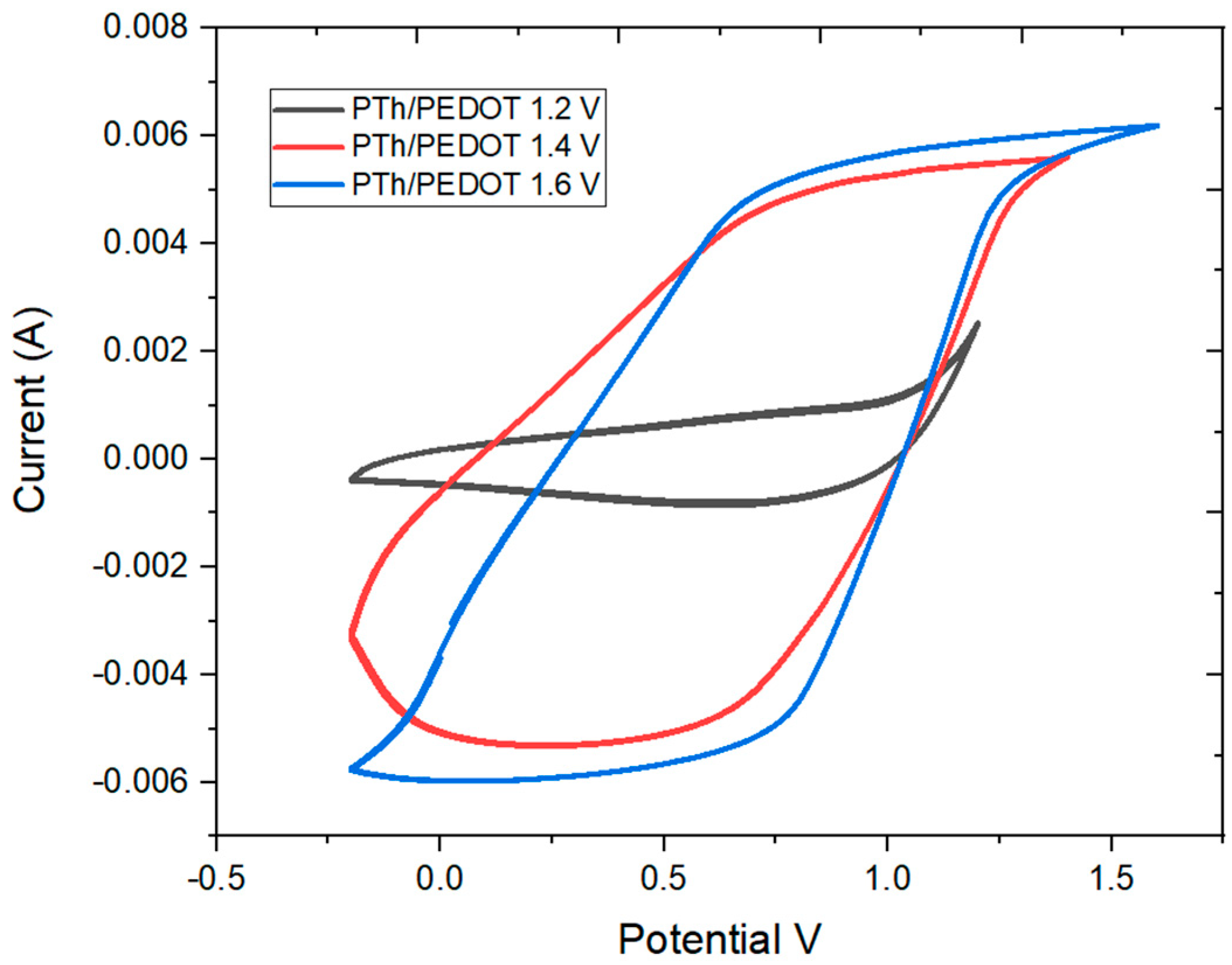
2.4. Electrochemical Characterization

In Figure 10a, stability tests of PTh are observed, indicating that materials synthesized in the potential window of −0.2 V at [1.4 and 1.6] V vs. Ag/AgCl show better stability in the tested potential range. However, the film formed at 1.2 V inversion potential exhibits higher conductivity (Figure 10b). The cyclic voltammetry curve shows a similar area under both the anodic and cathodic regions, suggesting a reversible process. As the number of cycles increases, this reversibility diminishes.
The PTh/PEDOT copolymer demonstrates greater stability in the stability tests (Figure 10c) compared to its monomeric predecessors. In the cyclic voltammetry curve of the PTh/PEDOT copolymer synthesized in the potential window of −0.2 V at 1.2 V vs. Ag/AgCl (LiClO4/ACN), material loss is observed when comparing cycle 1 and cycle 500 due to the decrease in the area under the curve. However, this decrease remains nearly constant compared to the behavior exhibited by PEDOT synthesized in the same potential window. Additionally, the maximum current levels remain constant, which is not the case with PTh synthesized in the same potential window.
In the stability-test results for the PTh/PEDOT copolymers synthesized in the potential windows of −0.2 V at [1.4 and 1.6] V vs. Ag/AgCl (LiClO4/ACN), material stability is evident as the area under the curve remains constant during successive cycles. However, the overoxidation of PTh observed during the synthesis of this material seems to influence these results, as the area under the curve of the corresponding cyclic voltammetry is smaller than that of the copolymer synthesized in the potential window of −0.2 V at 1.2 V vs. Ag/AgCl (LiClO4/ACN). Additionally, the obtained response exhibits resistive behavior to the incorporation of the doping anion, possibly resulting in the formation of a compact material. In both copolymers, the maximum current remains constant.
For those materials that withstand overoxidation after applying 500 charge/discharge cycles and maintain the area under the curve, they exhibit better stability for use as an anode in lithium-ion batteries. This test serves as an indicator of the material’s lifespan. PEDOT is less stable after applying 500 charge/discharge cycles in a potential window of −0.2 to 1.9 V vs. Ag/AgCl (LiClO4/ACN), and PTh exhibits greater stability, although the amount of material obtained is lower than that of PEDOT. However, the copolymerization of these two materials showed better resistance in the same stability tests, indicating a synergistic effect between them. To better define this synergistic effect, the following study will focus on understanding the lithium-ion charging capacity of different materials.

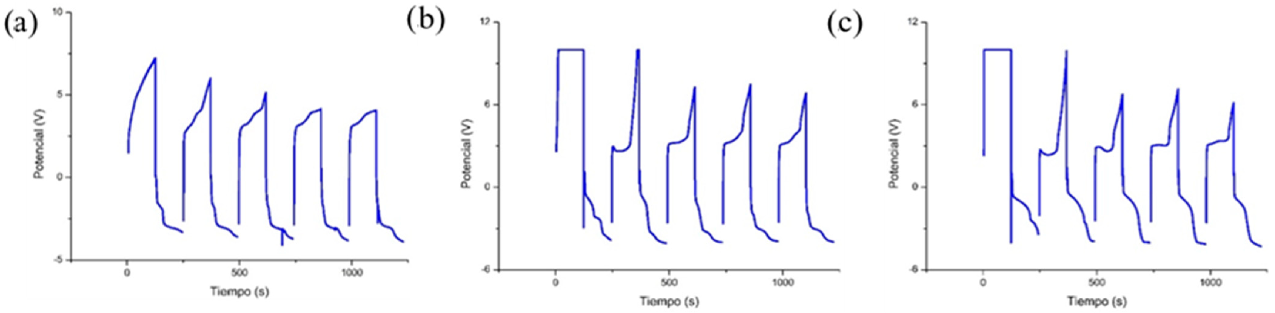
2.4.1. Pulsed Chronoamperometry (Charge Capacity)

The charge capacity of the PTh/PEDOT copolymer (Figure 11), synthesized in the potential window of −0.2 V to 1.2 V vs. Ag/AgCl (LiClO4/ACN), had a maximum representative potential for the charge capacity characterization of 7.24 V, which decreases to 3.79 V starting from the fifth charge/discharge cycle. The PTh/PEDOT copolymer synthesized in the potential window of −0.2 V to 1.4 V vs. Ag/AgCl (LiClO4/ACN) exhibited a maximum representative potential for the charge capacity of 10.12 V, decreasing to 6.1 V from the fifth charge/discharge cycle. Finally, the PTh/PEDOT copolymer synthesized in the potential window of −0.2 V to 1.4 V vs. Ag/AgCl (LiClO4/ACN) had a maximum representative potential for the charge capacity of 10.07 V, decreasing to 5.9 V from the fifth charge/discharge cycle. Over several cycles, the potential value decreases until it reaches 10.07 V and remains constant.

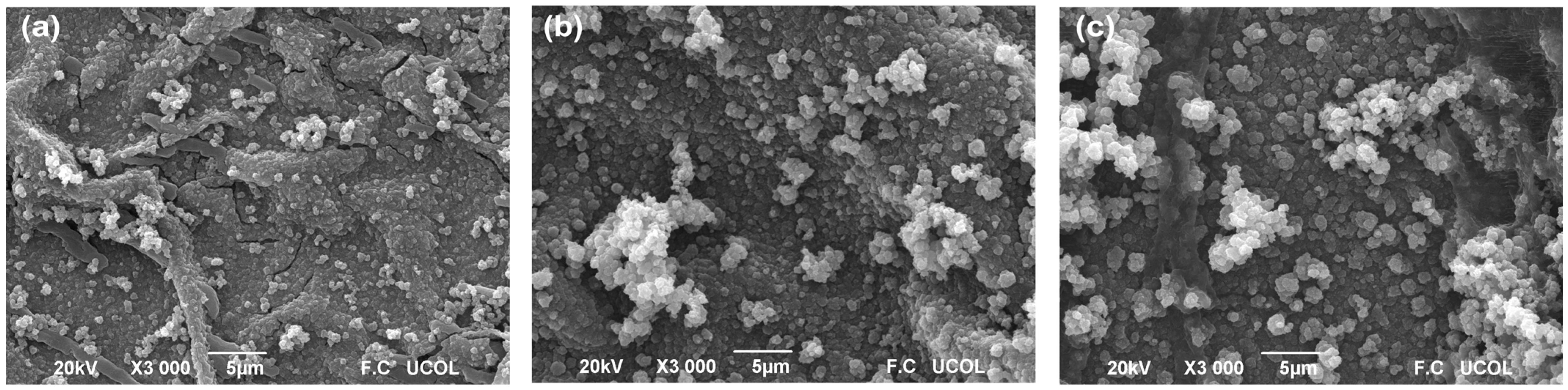
2.4.2. Scanning Electron Microscope (SEM) After Charge Capacity Test

When the incorporation and release of anions occur during the charging/discharging process, the structure and morphology of the materials change. Upon charging, there is an expansion effect on the polymer chains as anions are incorporated into the polymeric matrix, influencing the final morphology of the material. During discharging, the regular structure of the formed materials is altered, typically leading to material degradation attributed to the exit of anions from the matrix and a compaction of the structure [55].
In Figure 12a, SEM micrographs of the copolymer are shown; following the charging process, there is a slight structural change on the material surface, while still maintaining a significant number of structures.
The micrographs (Figure 12b) show a higher quantity of aggregates with sizes exceeding fifty micrometers and cauliflower-like shapes, as the structural change remains evident. However, the small fissures found in the potential window of 1.2 V vs. Ag/AgCl (LiClO4/ACN) did not appear in this potential window of 1.4 V vs. Ag/AgCl (LiClO4/ACN). This indicates better stability for the copolymer synthesized in the potential window of −0.2 V to 1.4 V. Structures that do not suffer such evident damage, fractures, and wear due to charge/discharge effects will be crucial in the intended application, where the transport of lithium species is of great relevance. The conduction of ions is a key aspect for the application of conductive polymers in lithium batteries, especially in high-speed applications.
As seen in Figure 12c, after the load capacity test, a significant portion of the material was lost, and the aggregates were fragmented without evidence of fissures or fractures in the polymeric structure. Despite being a less stable material, it possessed a greater amount of deposited material both before and after the load capacity tests.

3. Materials and Methods

3.1. Reagents

For the synthesis of the materials PTh and PEDOT, analytical-grade reagents were used. The monomers employed were bithiophene (Bth, Aldrich Steinheim, Germany, purity 97%) and 3,4-ethylenedioxythiophene (PEDOT, Aldrich Milwaukee, WI US, purity 97%). A lithium perchlorate (0.1 M LiClO4, Aldrich Milwaukee, WI US, purity 95%) and anhydrous acetonitrile as an organic medium (ACN, Aldrich Hamburg, Germany, purity 99.8%) were used as the supporting electrolyte.

3.2. Electrochemical Synthesis of Conductive Polymers

The synthesis was performed in a conventional three-electrode electrochemical system and electrochemical cell using an Autolab model 302N Potentiostat/Galvanostat. A fluorine-doped tin oxide (FTO, Aldrich, purity 99.99%)-coated substrate with an area of 1.35 cm2 was used as the working electrode. An Ag/AgCl reference electrode (BASi, model RE-5B Vleugelboot, Netherlands), which was incorporated into a compartment containing LiClO4/ACN, and perforated stainless steel (AI-304) as a counterelectrode were also employed (6 cm2) [57].
The electropolymerization was carried out by cyclic voltammetry at a scan rate of 100 mV/s for 30 cycles, applying a cathodic potential of −0.2 V vs. Ag/AgCl and varying the anodic switch potential in the range of 1.0 to 1.9 V vs. Ag/AgCl. In the electrochemical cell, 10 mL of the monomer/electrolyte solution was added. Regarding the electropolymerization of the two monomers, a 1:1 volume ratio was used in the cell (5 mL of bithiophene and 5 mL of 3,4-ethylenedioxythiophene) [58]. The monomers were prepared as solutions in 100 mL flasks at a concentration of 0.04 M. For the synthesis of PTh, 0.665 g of bithiophene (Bth) was weighed and diluted with a 0.1 M LiClO4 solution in acetonitrile. For the synthesis of PEDOT, 0.4272 mL of 3,4-ethylenedioxythiophene was measured and diluted with a 0.1 M LiClO4 solution in acetonitrile. Electropolymerization occurred in a nitrogen atmosphere.
To determine the optimal range of oxidation potential for the monomers and copolymer, preliminary tests were conducted under the same operating conditions: concentration, temperature, scan rate, and number of cycles. The reduction potential was set at −0.2 V vs. Ag/AgCl for all experiments. The oxidation potentials for the monomers PTh and PEDOT were 1.1, 1.2, 1.3, 1.4, 1.5, 1.6, 1.7, 1.8, and 1.9 V vs. Ag/AgCl, and for the copolymer PTh/PEDOT, they were 1.2, 1.4, and 1.6 V vs. Ag/AgCl.

3.3. Materials Characterization

Once all the materials were synthesized, only those materials that were electrodeposited within the same potential windows used for copolymerization were characterized. Two different batches of materials were generated to assess the stability of the polymeric material: batch 1, where the materials were not subjected to any tests immediately after electrodeposition, and batch 2, where the materials underwent electrochemical charge/discharge tests.

3.4. Chemical Characterization

Fourier-transform infrared spectroscopy (FTIR) was performed on the materials PTh, PEDOT, and PTh/PEDOT to observe the presence of their functional groups. The analyses were conducted using Perkin Elmer Spectrum 100 model equipment.

3.5. Morphological Characterization

Optical microscopy, scanning electron microscopy, and atomic force microscopy were used to study the morphological characteristics of the samples. Optical microscopy (OM) was used to examine the electrodeposited material on the FTO substrate in detail, using a 1000X digital optical microscope as a first morphological analysis. For a better surface study of the samples, scanning electron microscopy (SEM) was performed with a Jeol instrument model JSM-6390LV (Japan) on samples modified by deposition of a gold monolayer using a Denton Vacuum DESK IV evaporator, while atomic force microscopy was performed with a Veeco by Bruker Innova scanning probe microscope.

3.6. Electrochemical Analysis

Electrochemical characterizations were performed using an Autolab model 302N Potentiostat/Galvanostat (Wuhan city, China) with a three-electrode cell for cyclic voltammetry and a two-electrode cell for chronoamperometry. Cyclic voltammetry involved applying a cyclic voltammetry to the synthesized and electrodeposited materials on the FTO substrate within a potential window of −0.2 V to 1.9 V vs. Ag/AgCl. For stability tests, 500 cycles were applied in the same potential range at a scan rate of 1000 mV/s. Charge capacity characterization used a chronoamperometry procedure in the charge/discharge module, imposing a constant current for a specific time, simulating the charging of the material with lithium ions, followed by a reversal of polarity to simulate discharge.

4. Conclusions

Applying different potential windows for the polymerization of conductive polymers on a substrate resulted in obtaining materials with unique characteristics that are modified by changing the synthesis conditions.
Proper verification of synthesis parameters when applying potential windows allows for control over material deposition to be used as an anode in lithium-ion batteries. A change in the potential window was capable of altering both the amount of deposited material and the morphology of the final material. Smaller potential windows resulted in lesser material deposition, and this deposition increased as the potential window was expanded.
Potential windows of −0.2 V to 1.2 V, 1.4 V, and 1.6 V vs. Ag/AgCl (LiClO4/ACN) were utilized as the initial, intermediate, and final potential windows for the materials that were synthesized. All measurements reference an Ag/AgCl reference electrode.
The initial materials exhibited minimal material deposition in comparison to the intermediate and final materials. To compensate for this, copolymerization of the materials PTh and PEDOT was successfully performed, resulting in a material that improved the shortcomings of the individual polymers.
The copolymer improved in terms of the amount of material deposited on the substrate. PTh addressed the instability presented by PEDOT, enhancing the charge storage capacity of the two materials together and their capacitive effect. The presence of both materials in copolymerization allowed for significant enhancement of these materials, surpassing not only the sum of their individual capacities but also setting the stage for the true synergistic effect of copolymerization.
As for the best resulting material to be considered as an anode in a lithium-ion battery, the copolymer synthesized in the potential window of −0.2 V to 1.4 V vs. Ag/AgCl (LiClO4/ACN) exhibited the best charge storage properties. It demonstrated unique characteristics, including a substantial amount of deposited material, covering the entire substrate area used. Furthermore, it displayed robust stability over five hundred charge and discharge cycles, with electrical conductivity remaining constant. It matched the conductivity exhibited by the PEDOT materials synthesized in this work, which is of great significance, as PEDOT is considered one of the finest conductive materials in the field of conductive polymers.
Copolymerization successfully improved the two polymers employed in this study, PTh and PEDOT. Therefore, the copolymer can be considered for use as an anode material in a lithium-ion battery.

Author Contributions

D.A.V.-L., conceptualization, investigation, methodology, and data curation; U.P.-G., conceptualization, investigation, funding acquisition, supervision, and writing—review and editing; L.A.M.D.P.-P., data curation, and writing—review and editing; N.V.G.-R., R.G.-A. and D.L.C.-G., supervision, validation, and writing—review and editing. All authors have read and agreed to the published version of the manuscript.

Funding

This research was funded by Tecnológico Nacional de México under financial support No. 17991.23-P.

Data Availability Statement

The data presented in this study are available upon request from the corresponding author.

Acknowledgments

D.A.V.-L. and D.L.C.-G. acknowledgement the scholarship and postdoctoral stay by SECIHTI-Mexico. U.P.-G. thanks the Tecnológico Nacional de México for the sabbatical stay (No. AS-2-068/2024).

Conflicts of Interest

The authors declare no conflicts of interest.

References

  1. Cumurcu, A.; Duvigneau, J.; Lindsay, I.D.; Schön, P.M.; Vancso, G.J. Multimodal imaging of heterogeneous polymers at the nanoscale by AFM and scanning near-field ellipsometric microscopy. Eur. Pol. J. 2013, 49, 1935–1942. [Google Scholar]
  2. Rotering, N.; Lic, M. Optimal Charge Control of Plug-In Hybrid Electric Vehicles in Deregulated Electricity Markets. IEEE Trans. Power Syst. 2011, 26, 1021–1029. [Google Scholar] [CrossRef]
  3. Zhu, Z.; Liu, C.; Xu, J.; Jiang, Q.; Shi, H.; Liu, E. Improving the electrical conductivity of PEDOT:PSS films by binary secondary doping. Electron. Mater. Lett. 2016, 12, 54–58. [Google Scholar] [CrossRef]
  4. Alemu, D.; Wei, H.-Y.; Ho, K.-C.; Chu, C.-W. Highly conductive PEDOT:PSS electrode by simple film treatment with methanol for ITO-free polymer solar cells. Energy Environ. Sci. 2012, 5, 9662–9671. [Google Scholar] [CrossRef]
  5. Zeng, L.C.; Li, W.H.; Jiang, Y.; Yu, Y. Recent progres in Li-S and Li Se batteries. Rare Met. 2017, 36, 339–364. [Google Scholar] [CrossRef]
  6. He, G.; Ji, X.L.; Nazar, L. High “C” rate Li-S cathodes: Sulfuer imbibed bimodal porous carbons. Energy Environ. Sci. 2011, 4, 2878–2883. [Google Scholar] [CrossRef]
  7. Ji, L.; Rao, M.; Aloni, S.; Wang, L.; Cairns, E.J.; Zhang, Y. Porous carbon nanofibers-sulfur composites electrodes for lithium/sulfur cells. Energy Environ. Sci. 2011, 4, 5053–5059. [Google Scholar] [CrossRef]
  8. Wang, L.; Liu, S.; Hu, J.; Zhang, X.; Li, X.; Zhang, G.; Li, Y.; Zheng, C.; Hong, X.; Duan, H. Tailoring polysulfide trapping and kinetics by engineering hollow carbon bubble nanocreactors for high-energy Li-S pouch cells. Nano Res. 2021, 14, 1355–1363. [Google Scholar] [CrossRef]
  9. Wang, S.; Chen, H.; Liao, J.; Sun, Q.; Zhao, F.; Luo, J.; Lin, X.; Niu, X.; Wu, M.; Li, R. Efficient trapping and catalytic conversion of polysulfides by VS4 nanosites for Li-S batteries. ACS Energy Lett. 2019, 4, 755–763. [Google Scholar] [CrossRef]
  10. Islam, M.S.; Driscoll, D.J.; Fisher, C.A.J.; Slater, P.R. Atomic-scale investigation of defects, dopants, and lithium transport in the LiFePO4 olive-type battery material. Chem. Mat. 2005, 17, 5085–5092. [Google Scholar] [CrossRef]
  11. Pang, Q.; Liang, X.; Kwok, C.Y.; Nazar, L.F. Advances in lithium-sulfur batteries based on multifunctional cathodes and electrolytes. Nat. Energy 2016, 1, 16132. [Google Scholar] [CrossRef]
  12. Wang, Q.; Yan, J.; Fan, Z. Carbon material for high volumetric performances supercapacitors: Design progress, challenges and opportunities. Energy Environ. Sci. 2016, 9, 729–762. [Google Scholar] [CrossRef]
  13. Jadhav, N.; Kasisomayajula, S.; Gelling, V. Polypyrrole/metal Oxides-Based Composites/Nanocomposites for Corrosion Protection. Front. Mater. 2020, 7, 1–7. [Google Scholar] [CrossRef]
  14. Mohammad, M.; Farina, A. Polythiophene (PTh)-TiO2-Reduced Graphene Oxide (rGO) Nanocomposites Coating: Synthesis, Characterization, and Corrosion Protection Performance on Low-Carbon Stell in 3.5 wt% NaCl. ACS Omega 2022, 7, 46717–46730. [Google Scholar] [CrossRef]
  15. Ansari, M.O.; Mohammad, F. Thermal stability, electrical conductivity and ammonia sensing studies on p-toluenesulfonic acid doped polyaniline:titanium dioxide (pTSA/Pani:TiO2) nanocomposites. Sens. Act. B 2011, 157, 122–129. [Google Scholar] [CrossRef]
  16. Ansari, M.O.; Khan, M.M.; Ansari, S.A.; Raju, K.; Lee, J.; Cho, M.H. Enhanced thermal stability under DC electrical conductivity retention and visible light activity of Ag/TiO2@Polyaniline nanocomposite film. ACS Appl. Mater. Interfaces 2014, 6, 8124–8133. [Google Scholar] [CrossRef] [PubMed]
  17. Gonçalves, V.C.; Balogh, D.T. Optical chemical sensors using polythiophene derivates as active layer for detection of volatile organic compounds. Sens. Act. B 2012, 162, 307–312. [Google Scholar] [CrossRef]
  18. McCullough, R.D. The chemistry of conducting polythiophenes. Adv. Mater. 1998, 10, 93–116. [Google Scholar] [CrossRef]
  19. Murugavel, S.; Malathi, M. Synthesis and characterization of polythiophene nanofibers. Int. J. Chem. Sci. 2016, 14, 363–371. [Google Scholar]
  20. Yamamoto, T.; Maruyama, T.; Zhou, Z.-H.; Miyazaki, Y.; Kanbara, T.; Sanechika, K. New method using nickel (0) complex for preparation of poly(p-phenylene), poly(2,5-thiwnylwnw) and related π-conjugated polymers. Synth. Met. 1991, 41, 345–348. [Google Scholar] [CrossRef]
  21. Chandraprabha, G.; Sankarappa, T.; Lokhande, B.J.; Sujatha, T. Studies on conduction mechanism, magnetization and electrochemical propierties of polythiophene-cobalt nanocomposites. J. Nanosci. Technol. 2018, 4, 304–307. [Google Scholar] [CrossRef]
  22. Ko, H.C.; Kang, M.; Moon, B.; Lee, H. Enhancement of electrochomic contrast of poly(3,4-ethylenedioxythiophene) by incorporating a pendent viologen. Adv. Mat. 2004, 16, 1712–1716. [Google Scholar] [CrossRef]
  23. Gadgil, B.; Damlin, P.; Aaritalo, T.; Kankare, J.; Kvarnstrom, C. Eletrosynthesis and characterization of viologen cross linked thiophene copolymer. Electrochim. Acta 2013, 97, 378–385. [Google Scholar] [CrossRef]
  24. Ustamehmetoǧlu, B.; Sezer, E.; Kizilcan, N.; Yazic, P.; Tayyar, S.; Saraç, A.A.S. Inhibition of pyritr corrosion and photocorrosion by MEKFER modified carbazoles. Prog. Org. Coat. 2013, 76, 533–540. [Google Scholar] [CrossRef]
  25. Groenendaal, L.; Jonas, F.; Freitag, D.; Pielartzik, H.; Reynolds, J.R. Poly(3,4-ethylenedioxythiophene) and its derivatives: Past, present and future. Adv. Mater. 2000, 12, 481–494. [Google Scholar] [CrossRef]
  26. Lee, S.H.; Kim, Y.S.; Kim, J.H. Synthesis of polythiopehene/poly(3,4-ethylenedioxythiophene) Nanocomposites and their Application in thermoelectric devices. J. Electr. Mat. 2014, 43, 3276–3282. [Google Scholar] [CrossRef]
  27. Heinze, J.; Frontana-Uribe, B.A.; Ludwigs, S. Electrochemistry of Conducting Polymers Persistent Models and New Concepts. Chem. Rev. 2010, 110, 4724–4771. [Google Scholar] [CrossRef]
  28. Funt, B.L.; Lowen, S.V. Mechanistic studies of the electropolymerization of 2,2’-bithiophene and pyrrole to form conductiong polymers. Synth. Met. 1985, 11, 129–137. [Google Scholar] [CrossRef]
  29. Shi, H.; Liu, C.; Xu, J.; Song, H.; Lu, B.; Jiang, F.; Jiang, Q. Facile fabrication of PEDOT: PSS/polythiophenes bilayered nanofilms on pure organic electrodes and their thermoelectric performance. ACS Appl. Mat. Interfaces 2013, 5, 12811–12819. [Google Scholar] [CrossRef]
  30. Yang, L.; Huang, X.; Gogoll, A.; Strømme, M.; Sjödin, M. Conducting redox polymer based anode materials for high power electrical energy storage. Electrochim. Acta 2016, 204, 270–275. [Google Scholar] [CrossRef]
  31. Lacerda, G.R.B.S.; Calado, C.R.; Calado, H.D.R. Electrochromic and electrochemical properties of copolymer films based on EDOT and phenylthiophene derivatives. J. Solid State Electrochem. 2019, 23, 823–835. [Google Scholar] [CrossRef]
  32. Liu, F.-H.; Bai, J.; Yu, G.; Ma, F.-H.; Hou, Y.-J.; Niu, H.-J. Synthesis, electrochromic properties and flash memory behaviors of novel DAD polyazomethines containing EDOT and thiophene units. Org. Electron. 2020, 77, 105538. [Google Scholar] [CrossRef]
  33. Topal, S.; Topal, S.; Sezer, E.; Ustamehmetoglu, B.; Ozturk, T. Flexible energy storage device fabricated by electrochromic smart copolymer based on thienothiophene-triphenyamine and EDOT. J. Energy Storage 2024, 99, 113272. [Google Scholar] [CrossRef]
  34. Yılmaz, K.; Karaman, M. Highly conductive and uniform PEDOT on poly(acrylic acid-vinylbenzyl chloride) functionalized surfaces. Surf. Interfaces 2024, 55, 105320. [Google Scholar] [CrossRef]
  35. Gök, A.; Omastova, M.; Yavuz, A. Synthesis and characterization of polythiophenes prepared in the presence of surfactants. Synth. Met. 2007, 157, 23–29. [Google Scholar] [CrossRef]
  36. Karim, M.R.; Lee, C.J.; Lee, M.S. Synthesis and characterization of conducting polythiophene/carbon nanotubes composites. J. Polym. Sci. Part A Polym. Chem. 2006, 44, 5283–5290. [Google Scholar] [CrossRef]
  37. Popov, A.; Brasiunas, B.; Mikoliunaite, L.; Bagdziunas, G.; Ramanavicius, A.; Ramanaviciene, A. Comparative study of polyaniline (PANI), poly (3, 4-ethylenedioxythiophene) (PEDOT) and PANI-PEDOT films electrochemically deposited on transparent indium thin oxide-based electrodes. Polymer 2019, 172, 133–141. [Google Scholar] [CrossRef]
  38. Zhu, M.; Eyraud, M.; Judikael, L.-R.; Ahmed, N.A.; Boulc’h, F.; Alfonso, C.; Knauth, P.; Flory, F. Simple approach for the fabrication of PEDOT-coated Si nanowires. Beilstein J. Nanotech. 2015, 6, 640–650. [Google Scholar] [CrossRef]
  39. Patil, B.H.; Jagadale, A.D.; Lokhande, C.D. Synthesis of polythiophene thin films by simple successive ionic layer adsorption and reaction (SILAR) method for supercapacitor application. Synth. Met. 2012, 162, 1400–1405. [Google Scholar] [CrossRef]
  40. Kumarraja, M.; Pitchumani, K. Simple and efficient reduction of nitroarenes by hydrazine in faujasite zeolites. Appl. Cat. A Gen. 2004, 265, 135–139. [Google Scholar] [CrossRef]
  41. Baderstscher, M.; Bühlmann, P.; Pretsch, E. Structure Determination of Organic Compounds: Tables of Spectra Data, 4th ed.; Springer: Berlin/Heidelberg, Germany, 2009. [Google Scholar]
  42. Schuhmann, W.; Kranz, C.; Wohlschläger, H.; Strohmeier, J. Pulse technique for the electrochemical deposition of polymer films on electrodes surfaces. Biosens. Bioelectron. 1997, 12, 1157–1167. [Google Scholar] [CrossRef]
  43. Kaynak, A. Effect of synthesis parameters on the surface morphology of conducting polypyrrole films. Mater. Res. Bull. 1997, 32, 271–285. [Google Scholar] [CrossRef]
  44. Kiss, L.; Bôsz, D.; Koväcs, F.; Li, H.; Nagy, G.; Kunsagi-Máté, S. Investigation of pheno electrooxidation in aprotic non-aqueous solvents by using cyclic and normal pulse voltammetry. Polym. Bull. 2019, 76, 5849–5864. [Google Scholar] [CrossRef]
  45. Band, L.E. Spatial aggregation of complex terrain. Geograph. Anal. 1989, 21, 279–293. [Google Scholar] [CrossRef]
  46. Froeck, C.; Bartl, A.; Dunsch, L. STM-and AFM-investigations of one-and two-dimensional polypyrrole structures on electrodes. Electrochim. Acta 1995, 40, 1421–1425. [Google Scholar] [CrossRef]
  47. Mardia, K.V. Statistics of Directional Data. J. Royal Stat. Soc. Series B (Method) 1975, 37, 349–371. [Google Scholar] [CrossRef]
  48. Fingleton, B.; Upton, G.J. Spatial Data Analysis by Example. In Vol. 1: Point Pattern and Quantitative Data; John Wiley & Sons Ltd.: Hoboken, NJ, USA, 1985. [Google Scholar]
  49. Jonda, C.; Mayer, A.B.R.; Stolz, U.; Elschner, A.; Karbach, A. Surface roughness effects and their influence on the degradation of organic light emitting divices. J. Mat. Sci. 2000, 35, 5645–5651. [Google Scholar] [CrossRef]
  50. Carneiro, K.; Jesen, C.P.; Jørgensen, J.F.; Garnoes, J.; McKeown, P.A. Roughness parameters of surfaces by atomic force microscopy. CIRP Ann. 1995, 44, 517–522. [Google Scholar] [CrossRef]
  51. Yu, J.; Namba, Y. Atomic Surface roughness. Appl. Phys. Lett. 1998, 73, 3607–3609. [Google Scholar] [CrossRef]
  52. Suárez, M.F.; Compton, R.G. In situ atomic force microscopy study of polypyrrole synthesis and the volume changes induced by oxidation and reduction of the polymer. J. Electroanal. Chem. 1999, 462, 211–221. [Google Scholar] [CrossRef]
  53. Yang, Y.; Mu, S.; Chen, H. Electrochemical synthesis of polypyrrole for the immobilization of galactose oxidase. Synth. Met. 1998, 92, 173–178. [Google Scholar] [CrossRef]
  54. Castagnola, V.; Bayon, C.; Descamps, E.; Bergaud, C. Morphology and conductivity of PEDOT layers produced by different electrochemical routes. Synth. Met. 2014, 189, 7–16. [Google Scholar] [CrossRef]
  55. Silk, T.; Hong, Q.; Tamm, J.; Compton, R.G. AFM studies of polypyrrole film surface morphology I. The influence of film thickness and dopant nature. Synth. Met. 1998, 93, 59–64. [Google Scholar] [CrossRef]
  56. Schönherr, H. Imaging Polymer Morphology using Atomic Force Microscopy. In Polymer Morphology: Principles, Characterization, and Processing; Guo, Q., Ed.; Wiley: Hoboken, NJ, USA, 2016; Chapter 6; pp. 100–117. [Google Scholar] [CrossRef]
  57. Tüken, T.; Yazıcı, B.; Erbil, M. Electrochemical synthesis of polythiophene on nickel coated mild steel and corrosion performance. Appl. Surf. Sci. 2005, 239, 398–409. [Google Scholar] [CrossRef]
  58. Li, X.; Lu, M.; Li, H. Electrochemical copolymerization of pyrrole and thiophene nanofibrils using template-synthesis method. J. Appl. Pol. Sci. 2002, 86, 2403–2407. [Google Scholar] [CrossRef]
Figure 1. Polymerization voltamperograms of PTh/PEDOT copolymers in the potential windows of 1.2 V, 1.4 V, and 1.6 V vs. Ag/AgCl (LiClO4/ACN).
Condensedmatter 10 00026 g001
Figure 2. FTIR spectra of deposited films of (a) PTh, (b) PEDOT, and (c) PTh/PEDOT at different potential windows from −0.2V to 1.6 V vs. Ag/AgCl Ag/AgCl (LiClO4/ACN) on FTO.
Condensedmatter 10 00026 g002
Figure 3. Optical micrographs of synthetized materials, (A) PTh, (B) PEDOT, and (C) PTh/PEDOT, at potential windows from (I) −0.2 V to 1.2 V, (II) −0.2 V to 1.4 V, and (III) −0.2 V to 1.6 V vs. Ag/AgCl (LiClO4/ACN).
Condensedmatter 10 00026 g003
Figure 4. SEM Micrographs of synthetized materials, (A) PTh, (B) PEDOT, and (C) PTh/PEDOT, at potential windows from (I) −0.2 V to 1.2 V, (II) −0.2 V to 1.4 V, and (III) −0.2 V to 1.6 V vs. Ag/AgCl (LiClO4/ACN).
Condensedmatter 10 00026 g004
Figure 5. Rq vs. potential windows of polymers: PTh, PEDOT, and PTh/PEDOT.
Condensedmatter 10 00026 g005
Figure 6. AFM micrography of FTO substrate 50 × 50 µm.
Condensedmatter 10 00026 g006
Figure 7. AFM micrographs of PTh at potential windows: (a) 1.2 V, (b) 1.4 V, and (c) 1.6 V vs. Ag/AgCl (LiClO4/ACN).
Condensedmatter 10 00026 g007
Figure 8. AFM micrographs of PEDOT at potential windows: (a) 1.2 V, (b) 1.4 V, and (c) 1.6. V vs. Ag/AgCl (LiClO4/ACN).
Condensedmatter 10 00026 g008
Figure 9. AFM micrographs of PTh/PEDOT at potential windows: (a) 1.2 V, (b) 1.4 V, and (c) 1.6 V vs. Ag/AgCl (LiClO4/ACN).
Condensedmatter 10 00026 g009
Figure 10. Stability-test voltamperograms of (a) PTh, (b) PEDOT, and (c) PTh/PEDOT.
Condensedmatter 10 00026 g010
Figure 11. Chronoamperometry of the charge capacity test of PTh/PEDOT in the potential windows of (a) −0.2 to 1.2 V, (b) 0.2 to 1.4 V, and (c) −0.2 to1.6V vs. Ag/AgCl (LiClO4/ACN).
Condensedmatter 10 00026 g011
Figure 12. SEM micrography of copolymer after charge test: (a) −0.2 V to 1.2 V, (b) −0.2 V to 1.4 V, and (c) 0.2 V to 1.6 V vs. Ag/AgCl (LiClO4/ACN).
Condensedmatter 10 00026 g012
Disclaimer/Publisher’s Note: The statements, opinions and data contained in all publications are solely those of the individual author(s) and contributor(s) and not of MDPI and/or the editor(s). MDPI and/or the editor(s) disclaim responsibility for any injury to people or property resulting from any ideas, methods, instructions or products referred to in the content.

