
Underactuated Humanoid Peeling Approach for Pickled Mustard Tuber Based on Metamorphic Constraints


Abstract
:1. Introduction
2. Design of Pickled Mustard Tuber Peeling Robot
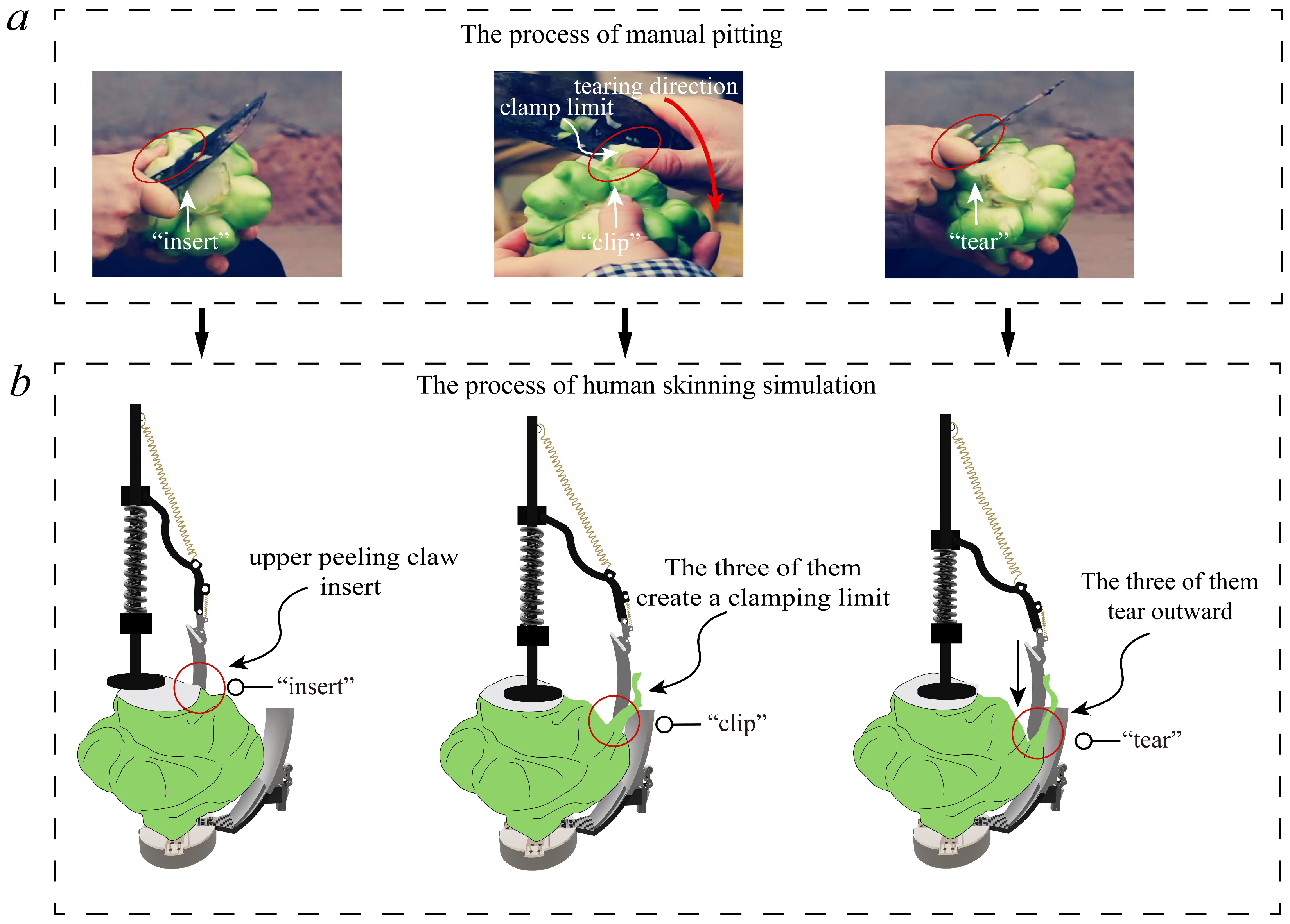
2.1. Human-Like Peeling Process
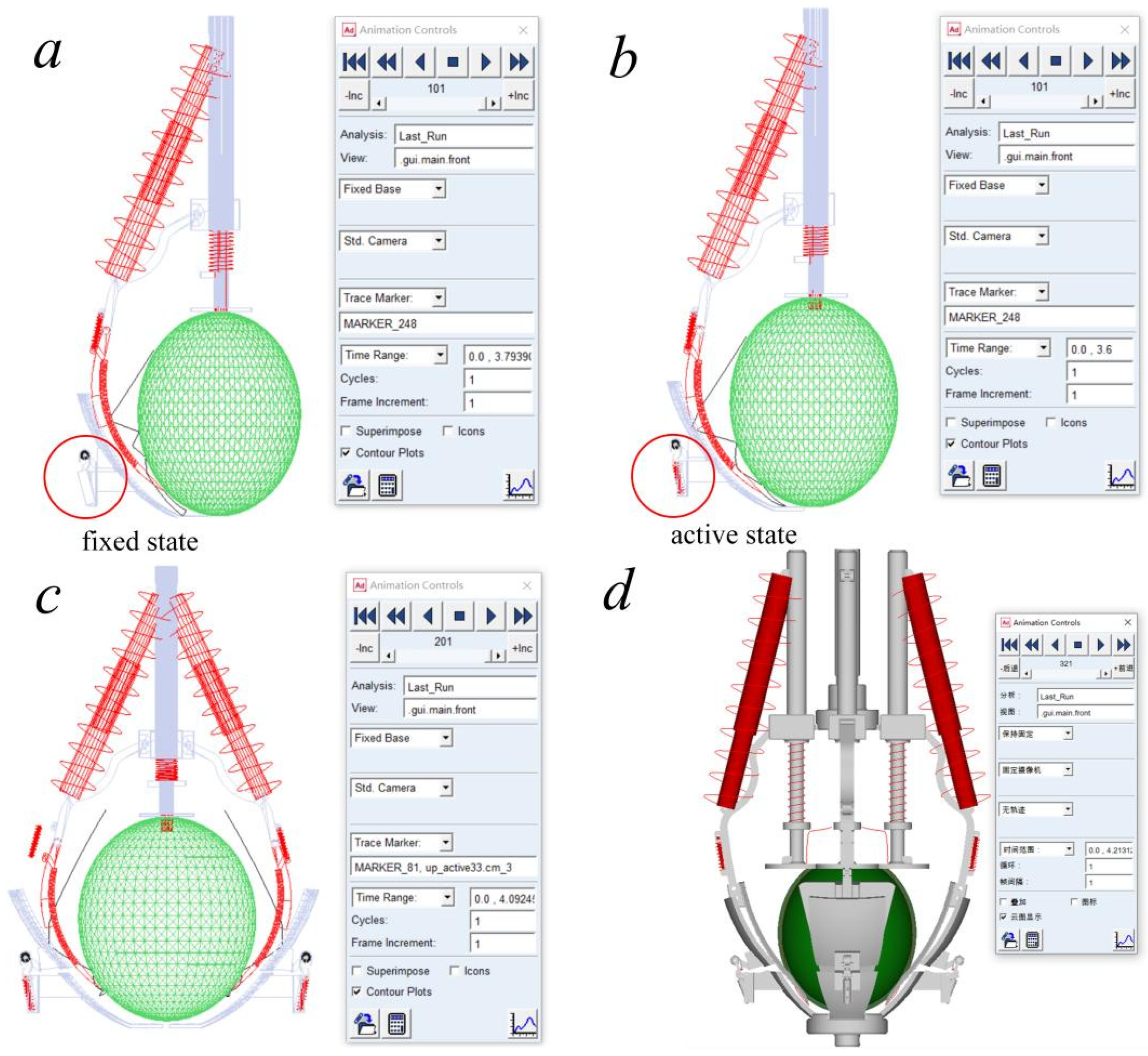
2.2. Metamorphic Mechanism Simulation
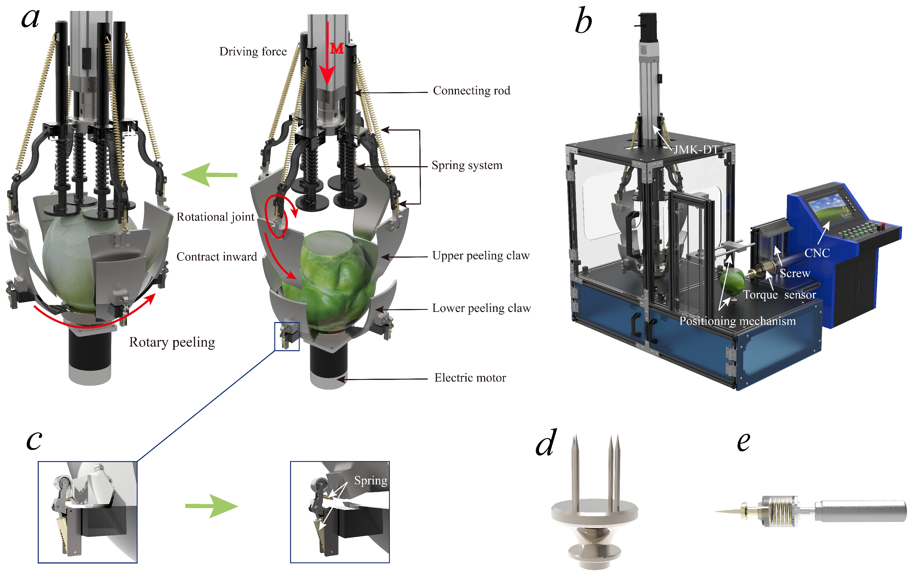
2.3. System Architecture of PMT Peeling Approach
3. Mechanical Analysis of Metamorphic Peeling Finger
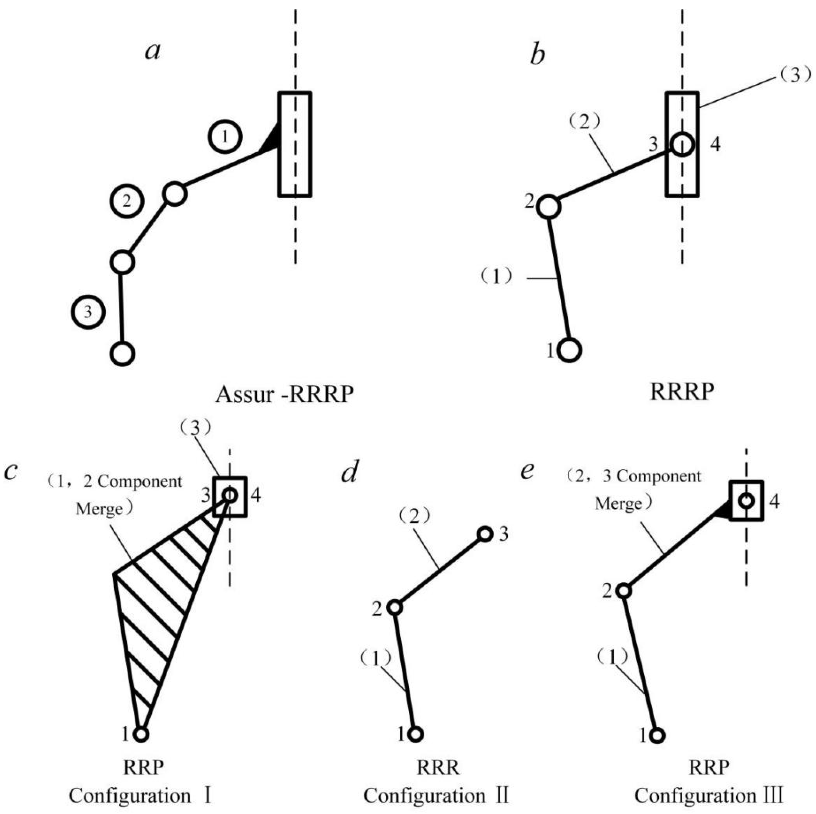
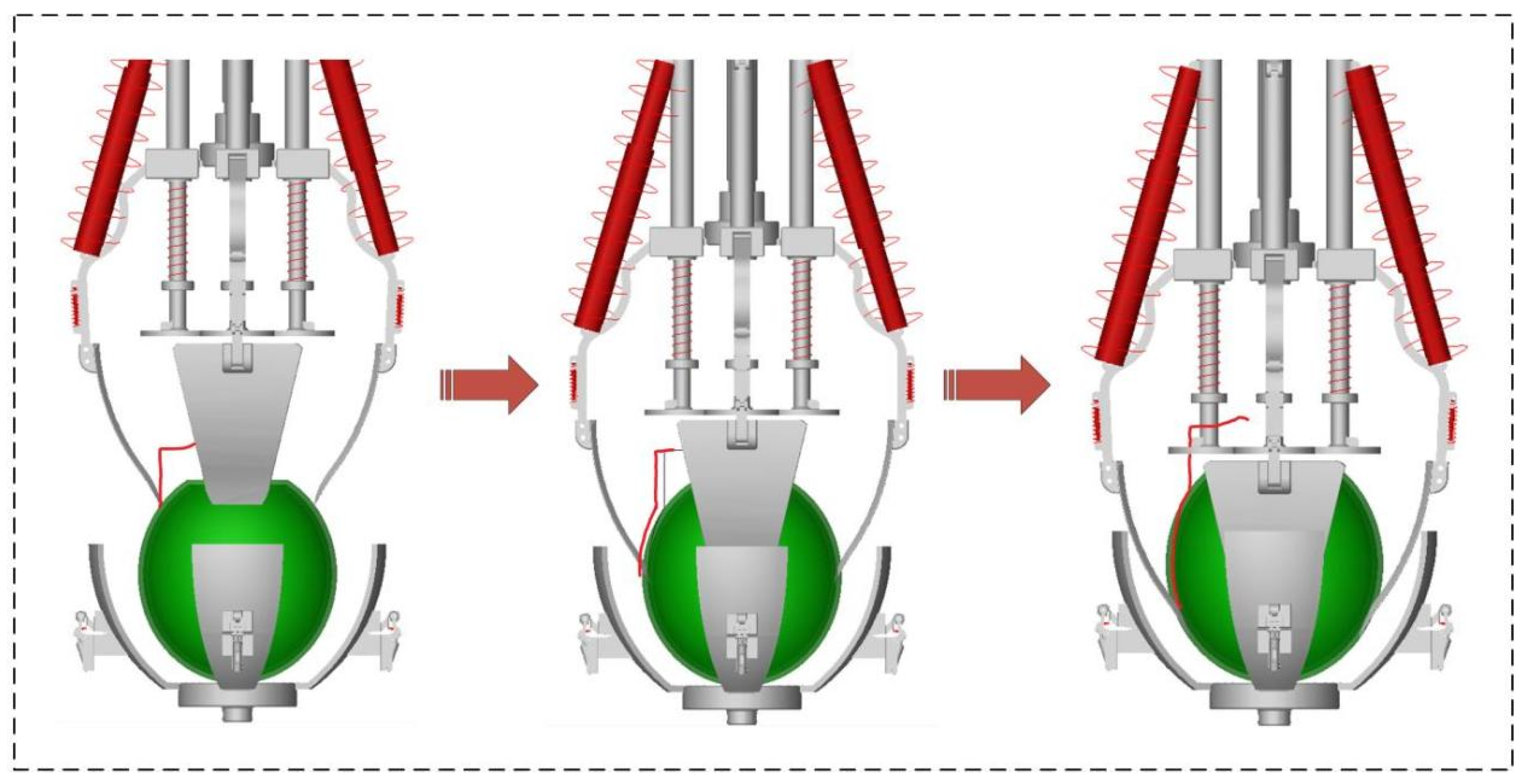
3.1. Degradation Process of Metamorphic Peeling Finger
3.2. Modular Mechanical Analysis of Metamorphic Peeling Finger
4. Trajectory Predicting of Metamorphic Peeling Finger
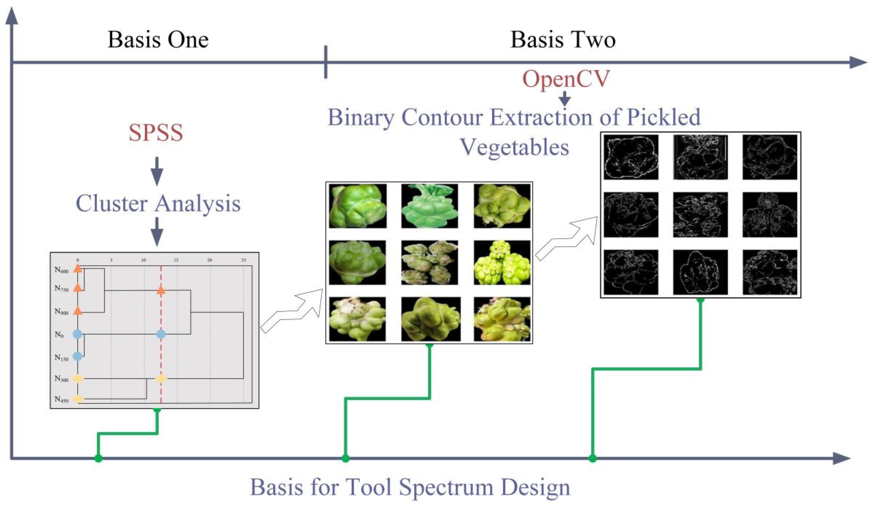
4.1. Morphological Statistical Analysis of PMT
4.2. Configuration of Peeling Finger
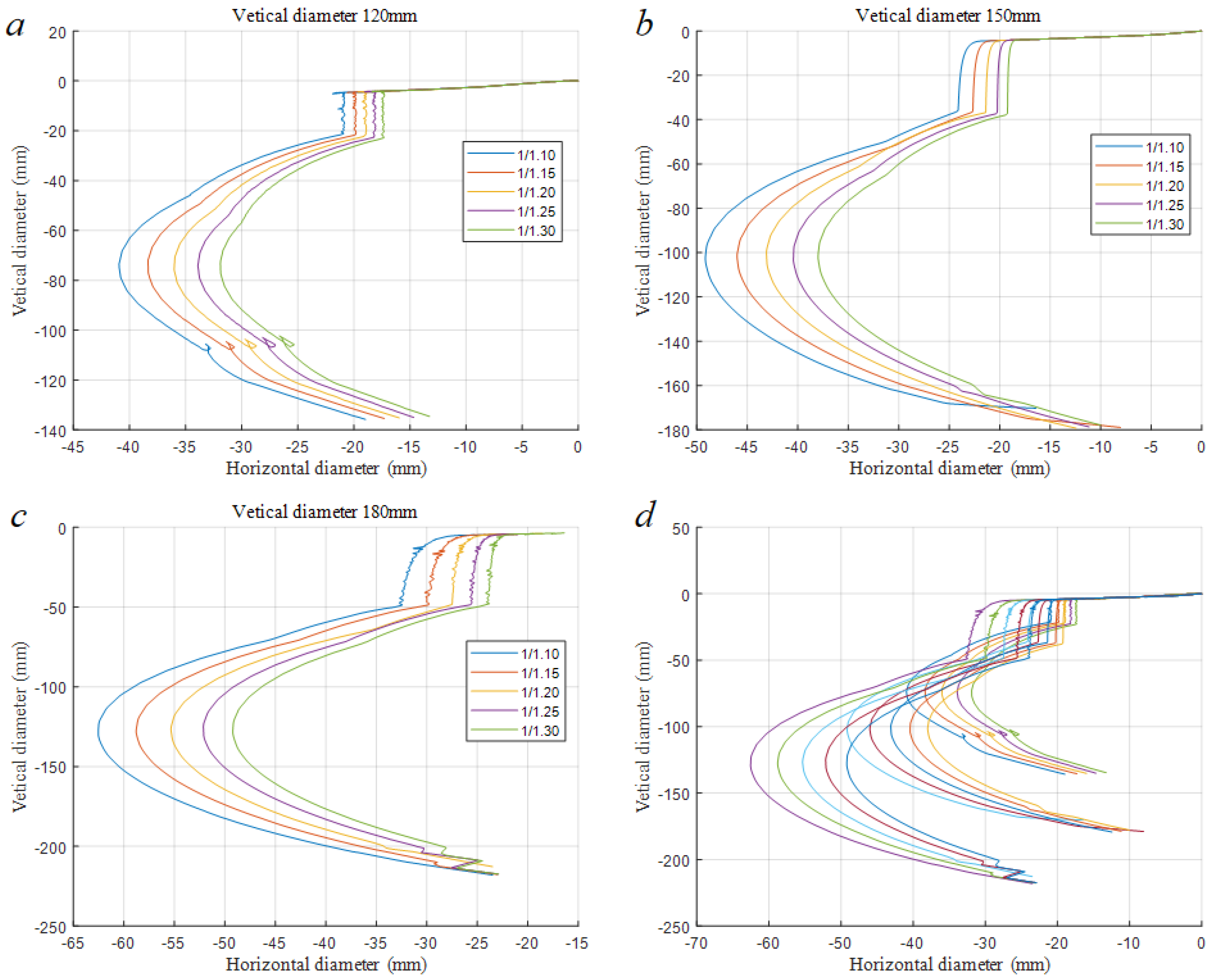
4.3. Peeling Trajectory Prediction
5. Simulation and Analysis
5.1. Virtual Prototyping Modeling
5.2. Peeling Trajectory Prediction
5.2.1. Peeling Mechanism Optimization
5.2.2. Peeling Trajectory Verification
6. Conclusions and Future Work
7. Patents
Author Contributions
Funding
Institutional Review Board Statement
Data Availability Statement
Conflicts of Interest
References
- Zhang, C.; Zhang, J.; Liu, D. Biochemical changes and microbial community dynamics during spontaneous fermentation of Zhacai, a traditional pickled mustard tuber from China. Int. J. Food Microbiol. 2021, 347, 109199. [Google Scholar] [CrossRef] [PubMed]
- Xu, L.; Pang, Y.; Liu, W.; Chen, H.; Huang, S.; Zhu, L. Hypersaline Wastewater Produced from Pickled Mustard Tuber (Chinese Zhacai): Current Treatment Status and Prospects. Water 2022, 14, 1508. [Google Scholar] [CrossRef]
- Rock, C.; Yang, W.; Goodrich-Schneider, R.; Feng, H. Conventional and alternative methods for tomato peeling. Food Eng. Rev. 2012, 4, 1–15. [Google Scholar] [CrossRef]
- Xie, D.; Zhang, C.; Wu, X.; Wang, W.; Liu, L.; Chen, L. Design and Test of Garlic Seed Placer with Seed Disturbing Tooth Assisted Air Suction. Trans. Chin. Soc. Agric. Mach. 2022, 53, 47–57. [Google Scholar]
- Fadeyibi, A.; Olusola, F.A. Design and performance evaluation of a multi-tuber peeling machine. AgriEngineering 2020, 2, 55–71. [Google Scholar] [CrossRef]
- Yen, K.Y.; Radhwan, H.; Shayfull, Z.; Nasir, S.M. Design and Analysis of Garlic Peeler Machine. In Proceedings of the IOP Conference Series: Materials Science and Engineering, Bangkok, Thailand, 4–5 February 2020. [Google Scholar]
- Shen, Y.; Khir, R.; Wood, D.; McHugh, T.H.; Pan, Z. Pear peeling using infrared radiation heating technology. Innov. Food Sci. Emerg. Technol. 2020, 65, 102474. [Google Scholar] [CrossRef]
- Chemat, F.; Khan, M.K. Applications of ultrasound in food technology: Processing, preservation and extraction. Ultrason. Sonochemistry 2011, 18, 813–835. [Google Scholar] [CrossRef]
- Das, D.J.; Barringer, S.A. Potassium hydroxide replacement for lye (sodium hydroxide) in tomato peeling. J. Food Process. Preserv. 2006, 30, 15–19. [Google Scholar] [CrossRef]
- Schaflinger, U. Centrifugal separation of a mixture. Fluid Dyn. Res. 1990, 6, 213. [Google Scholar] [CrossRef]
- Xie, Z.; Shen, P.; Li, H.; Dong, W.; Zhang, H.; Zhao, X. Design of New Annular Pickled Tuber Mustard Peeler. Light Ind. Mach. 2019, 37, 25–28. [Google Scholar]
- Hou, S.; Zou, Z.; Wei, Z.; Zhu, Y.; Chen, H. Design and Experiment of Flexible Mechanical Soybean Precision Seed-metering Device. Trans. Chin. Soc. Agric. Mach. 2020, 51, 77–86+108. [Google Scholar]
- Li, X.; Wang, W.; Zhao, G.; Sun, C.; Hu, P.; Ji, J. Design and Experiment of Longitudinal Axial Flow Double Flexible Rolling and Kneading Threshing Device for Millet. Trans. Chin. Soc. Agric. Mach. 2021, 52, 113–123. [Google Scholar]
- Ji, J.; Li, M.; Zhao, K.; Ma, H. Design and Experiment of Flexible Profiling Picking End-effector for Agaricus bisporus. Trans. Chin. Soc. Agric. Mach. 2023, 54, 104–115. [Google Scholar]
- Pi, J.; Liu, J.; Xu, L.; Yan, N.; Zhou, K.; Qian, M. Structure Design and Experiment of Three Finger Flexible Pneumatic Gripper. Trans. Chin. Soc. Agric. Mach. 2020, 51, 93–101. [Google Scholar]
- Li, X.; Sun, C.; Zhang, W.; Wang, S.; Gao, L. Design and Test of combined Garlic Flexible peeling Device. Trans. Chin. Soc. Agric. Mach. 2023, 54, 132–141. [Google Scholar]
- Shi, J. Novel Flexible Machine of Peeling Litchi. Light Ind. Mach. 2012, 30, 73–74. [Google Scholar]
- Peng, S. Research on Flexible Peeling Machine of Lotus Root. Packag. Food Mach. 2004, 22, 7–8. [Google Scholar]
- Yu, G.; Zheng, H.; Xue, X. Optimization Design and Experiment of Auto-adaptive Profiling Sweet Potato Peeler. Trans. Chin. Soc. Agric. Mach. 2021, 52, 135–142. [Google Scholar]
- Hao, Y.; Wang, Z.; Zhou, Y.; Zhou, W.; Cai, T.; Zhang, J.; Sun, F. A Soft Enveloping Gripper with Enhanced Grasping Ability via Morphological Adaptability. Adv. Intell. Syst. 2023, 5, 2200456. [Google Scholar] [CrossRef]
- Vukobratović, M.; Stepanenko, J. Mathematical models of general anthropomorphic systems. Math. Biosci. 1973, 17, 191–242. [Google Scholar] [CrossRef]
- Hao, Y.; Biswas, S.; Hawkes, E.W.; Wang, T.; Zhu, M.; Wen, L.; Visell, Y. A Multimodal, Enveloping Soft Gripper: Shape Conformation, Bioinspired Adhesion, and Expansion-Driven Suction. IEEE Trans. Robot. 2020, 37, 350–362. [Google Scholar] [CrossRef]
- Wang, M.; Yuan, J.; Bao, S.; Du, L.; Ma, S. Research on Self-Stiffness Adjustment of Growth-Controllable Continuum Robot (GCCR) Based on Elastic Force Transmission. Biomimetics 2023, 8, 433. [Google Scholar] [CrossRef] [PubMed]
- Gao, G.; Wang, H.; Fan, J.; Xia, Q.; Li, L.; Ren, H. Study on stretch-retractable single-section continuum manipulator. Adv. Robot. 2019, 33, 1–12. [Google Scholar] [CrossRef]
- Dai, J.; Zoppi, M.; Kong, X. Advances in reconfigurable mechanisms and robotics I. In Proceedings of the Second International Conference on Reconfigurable Mechanisms and Robots, Tianjin, China, 9–11 July 2012. [Google Scholar]
- Yang, Q.; Sun, B.; Li, S.; Dai, J. Reliability Optimization Design Method of Constrained Metamorphic Mechanism Oriented to the Stability of Configuration Transformation. J. Mech. Eng. 2023, 59, 22–37. [Google Scholar]
- Li, S.; Dai, J. Structure synthesis of single—Driven metamorphic mechanisms based on the augmented Assur groups. J. Mech. Robot. 2012, 4, 031004. [Google Scholar] [CrossRef]
- Xiao, B.; Xu, Q.; Li, B. The Influence of Different Nitrogen Application Rates on Yield and Quality of Stem Mustard. South China Agric. 2022, 16, 112–114+118. [Google Scholar]
- Kumar, P.; Chakrabarti, D. Design of Pineapple Peeling Equipment. In Advances in Mechanical Engineering and Technology: Proceedings of 6th International Conference on Advanced Production and Industrial Engineering (ICAPIE)-2021; Springer: Singapore, 2022. [Google Scholar]
- Wang, Y.; Yao, Y.; Li, S.; Luo, D. Dynamics Simulation Analysis of Submachine Gun Based on ADAMS. Ordnance Ind. Autom. 2023, 5, 5. [Google Scholar]
- Liu, L.; Liu, H.; Du, Y.; Mao, E.; Zhang, Y.; Yang, F. Design and Experiment of Seed Corn Peeling Mechanism Based on TRIZ Theory. Trans. Chin. Soc. Agric. Mach. 2022, 53, 131–141. [Google Scholar]
- Gao, Y.; Dai, Q.; Zhang, N. 3D model comparison using spatial structure circular descriptor. Pattern Recognit. 2010, 43, 1142–1151. [Google Scholar] [CrossRef]


| Symbol | Definition |
|---|---|
| N5, N6, N7 | Link N2N3, N3N4, and the centroid of the slider. |
| α | Geometric constraint angle of variable cell revolute pair. |
| dk, dk1 | Current length of springs 1 and 2 |
| Fk, Fk1 | Spring force of springs 1 and 2 |
| θ | Angle between the force direction of spring 1 and the link N3N4. |
| dh, dm | Distance between the two ends of spring 1 and point N4. |
| d1, d2 | Distance between the two ends of spring 2 and point N3. |
| F7, T3 | External force and torque applied to the slider. |
| F5, F6 | The link N2N3 and N3N4 experience forces due to the sliding of the slider. |
| T1, T2 | The link N2N3 and N3N4 experience torques due to the sliding of the slider. |
| k | Spring constant |
| a | Original length of the spring |
| Pijx, Pijy | Distance in the x and y directions between points i and j. |
| Rix, Riy | Supporting reaction forces in the x and y directions acting on motion pair i. |
| Fix, Fiy | Forces acting on point i in the x and y directions. |
| Tij | Force applied at point i, causing torque at point j. |
| Ti | Torque acting at point i. |
| Tk | The torque due to the spring force at point N4, i.e., the constraint resistance torque provided by the variable cell subsystem. |
| T54, T64 | The torque caused by the gravitational forces of the two links at point N4. |
| ΔT | The driving torque of the variable cell revolute pair. |
| γ | The angle between the guide and the link N3N4. |
| Designation | Plant Height/cm | Plant Width/cm | Shape Index (Longitudinal Diameter/Transverse Stem) | Skin Elasticity/% | Net Yield/% |
|---|---|---|---|---|---|
| N0 | 45.5 | 47.9 | 1.32 | 7.62 | 39.39 |
| N150 | 46.3 | 48.4 | 1.38 | 8.62 | 39.89 |
| N300 | 46.9 | 46.2 | 1.20 | 8.28 | 43.35 |
| N450 | 44.9 | 46.9 | 1.18 | 12.19 | 42.33 |
| N600 | 43.2 | 44.3 | 1.15 | 7.45 | 40.42 |
| N750 | 44.3 | 45.3 | 1.17 | 7.62 | 39.86 |
| N900 | 44.3 | 48.0 | 1.15 | 6.99 | 39.03 |
| Component Name | Component Number | Adams Component Name | 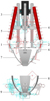 |
| Compression rod | 1,2 | up_mid | |
| Upper rod | 3 | up_mid2 | |
| Block | 4 | up_active1 | |
| Long link | 5 | up_active2 | |
| Short link, Upper gripper | 6,7 | up_active3 | |
| Lower gripper | 8 | under_active | |
| Placement board | 9 | under_stop1 | |
| under_stop2 | |||
| under_stop3 |
| volume of pickled mustard tubers | vertical diameter/ horizontal diameter | 1.10 | 1.15 | 1.20 | 1.25 | 1.30 |
| horizontal diameter | 11.82 | 11.30 | 10.83 | 10.40 | 10.00 | |
| component name | parameter type | simulation-optimized parameter results | ||||
| Spring a | stiffness coefficient | 8 × 10² | 8 × 10² | 8 × 10² | 8 × 10² | 8 × 10² |
| damping coefficient | 5 × 10² | 5 × 10² | 5 × 10² | 5 × 10² | 5 × 10² | |
| Spring b | stiffness coefficient | 1.6 × 10⁴ | 1.7 × 10⁴ | 1.8 × 10⁴ | 1.9 × 10⁴ | 2 × 10⁴ |
| damping coefficient | 1 × 10³ | 1 × 10³ | 1 × 10³ | 1 × 10³ | 1 × 10³ | |
| Pre-tightening Force | 2.5 × 101 | 2.5 × 101 | 2.5 × 101 | 2.5 × 101 | 2.5 × 101 | |
| Spring c | stiffness coefficient | 1 × 10⁴ | 1 × 10⁴ | 1 × 10⁴ | 1 × 10⁴ | 1 × 10⁴ |
| damping coefficient | 1 × 10³ | 1 × 10³ | 1 × 10³ | 1 × 10³ | 1 × 10³ | |
| Spring d | stiffness coefficient | 1 × 10⁴ | 1 × 10⁴ | 1 × 10⁴ | 1 × 10⁴ | 1 × 10⁴ |
| damping coefficient | 8 × 10² | 8 × 10² | 8 × 10² | 8 × 10² | 8 × 10² | |
| Spring e | stiffness coefficient | 1 × 10⁴ | 1 × 10⁴ | 1 × 10⁴ | 1 × 10⁴ | 1 × 10⁴ |
| damping coefficient | 8 × 10² | 8 × 10² | 8 × 10² | 8 × 10² | 8 × 10² | |
| volume of pickled mustard tubers | vertical diameter/ horizontal diameter | 1.10 | 1.15 | 1.20 | 1.25 | 1.30 |
| horizontal diameter | 13.64 | 13.04 | 12.50 | 12.00 | 11.54 | |
| component name | parameter type | simulation-optimized parameter results | ||||
| Spring a | stiffness coefficient | 8 × 10² | 8 × 10² | 8 × 10² | 8 × 10² | 8 × 10² |
| damping coefficient | 5 × 10² | 5 × 10² | 5 × 10² | 5 × 10² | 5 × 10² | |
| Spring b | stiffness coefficient | 1.2 × 10⁴ | 1.3 × 10⁴ | 1.4 × 10⁴ | 1.5 × 10⁴ | 1.6 × 10⁴ |
| damping coefficient | 6 × 10³ | 6 × 10³ | 6 × 10³ | 6 × 10³ | 6 × 10³ | |
| Pre-tightening Force | 2.5 × 101 | 2.5 × 101 | 2.5 × 101 | 2.5 × 101 | 2.5 × 101 | |
| Spring c | stiffness coefficient | 1 × 10⁴ | 1 × 10⁴ | 1 × 10⁴ | 1 × 10⁴ | 1 × 10⁴ |
| damping coefficient | 1 × 10³ | 1 × 10³ | 1 × 10³ | 1 × 10³ | 1 × 10³ | |
| Spring d | stiffness coefficient | 1 × 10⁴ | 1 × 10⁴ | 1 × 10⁴ | 1 × 10⁴ | 1 × 10⁴ |
| damping coefficient | 8 × 10² | 8 × 10² | 8 × 10² | 8 × 10² | 8 × 10² | |
| Spring e | stiffness coefficient | 1 × 10⁴ | 1 × 10⁴ | 1 × 10⁴ | 1 × 10⁴ | 1 × 10⁴ |
| damping coefficient | 8 × 10² | 8 × 10² | 8 × 10² | 8 × 10² | 8 × 10² | |
| volume of pickled mustard tubers | vertical diameter/ horizontal diameter | 1.10 | 1.15 | 1.20 | 1.25 | 1.30 |
| horizontal diameter | 16.36 | 15.65 | 15.00 | 14.40 | 13.85 | |
| component name | parameter type | simulation-optimized parameter results | ||||
| Spring a | stiffness coefficient | 6 × 10³ | 6 × 10³ | 6 × 10³ | 6 × 10³ | 6 × 10³ |
| damping coefficient | 5 × 10² | 5 × 10² | 5 × 10² | 5 × 10² | 5 × 10² | |
| Spring b | stiffness coefficient | 8 × 10³ | 9 × 10³ | 1 × 10⁴ | 1.1 × 10⁴ | 1.2 × 10⁴ |
| damping coefficient | 6 × 10³ | 6 × 10³ | 6 × 10³ | 6 × 10³ | 6 × 10³ | |
| Pre-tightening Force | 2.5 × 101 | 2.5 × 101 | 2.5 × 101 | 2.5 × 101 | 2.5 × 101 | |
| Spring c | stiffness coefficient | 1 × 10⁴ | 1 × 10⁴ | 1 × 10⁴ | 1 × 10⁴ | 1 × 10⁴ |
| damping coefficient | 1 × 10³ | 1 × 10³ | 1 × 10³ | 1 × 10³ | 1 × 10³ | |
| Spring d | stiffness coefficient | 1 × 10⁴ | 1 × 10⁴ | 1 × 10⁴ | 1 × 10⁴ | 1 × 10⁴ |
| damping coefficient | 8 × 10² | 8 × 10² | 8 × 10² | 8 × 10² | 8 × 10² | |
| Spring e | stiffness coefficient | 1 × 10⁴ | 1 × 10⁴ | 1 × 10⁴ | 1 × 10⁴ | 1 × 10⁴ |
| damping coefficient | 8 × 10² | 8 × 10² | 8 × 10² | 8 × 10² | 8 × 10² | |
| Vertical Diameter of Pickled Mustard Tubers | Vegetable Shape Index | Total Volume/cm3 | Skin Volume/cm3 | Trajectory Reconstruction Volume/cm3 | Meat Loss Rate% | Skin Tendon Residue Rate% |
|---|---|---|---|---|---|---|
| 18 cm | 1.10 | 2898.91 | 234.99 | 2666.50 | 8.02 | 1.10 |
| 1.15 | 2652.32 | 221.60 | 2441.11 | 7.96 | 4.69 | |
| 1.20 | 2435.90 | 209.58 | 2240.45 | 8.02 | 6.74 | |
| 1.25 | 2244.93 | 198.72 | 2064.75 | 8.03 | 9.33 | |
| 1.30 | 2075.58 | 188.87 | 1903.54 | 8.29 | 8.91 | |
| 15 cm | 1.10 | 1731.15 | 165.94 | 1550.29 | 10.45 | −8.99 |
| 1.15 | 1583.89 | 156.45 | 1416.34 | 10.58 | −7.09 | |
| 1.20 | 1454.65 | 147.93 | 1309.40 | 9.99 | 1.81 | |
| 1.25 | 1340.61 | 140.24 | 1201.79 | 10.36 | 1.01 | |
| 1.30 | 1239.47 | 133.27 | 1104.62 | 10.88 | −1.18 | |
| 12 cm | 1.10 | 928.55 | 108.86 | 823.31 | 11.33 | 3.33 |
| 1.15 | 849.56 | 102.61 | 752.63 | 11.41 | 5.54 | |
| 1.20 | 780.24 | 97.00 | 684.22 | 12.31 | 1.01 | |
| 1.25 | 719.07 | 91.93 | 628.75 | 12.56 | 1.75 | |
| 1.30 | 664.83 | 87.33 | 579.29 | 12.87 | 2.05 |
Disclaimer/Publisher’s Note: The statements, opinions and data contained in all publications are solely those of the individual author(s) and contributor(s) and not of MDPI and/or the editor(s). MDPI and/or the editor(s) disclaim responsibility for any injury to people or property resulting from any ideas, methods, instructions or products referred to in the content. |
© 2023 by the authors. Licensee MDPI, Basel, Switzerland. This article is an open access article distributed under the terms and conditions of the Creative Commons Attribution (CC BY) license (https://creativecommons.org/licenses/by/4.0/).
Share and Cite
Wan, H.; Chen, L.; Xiao, J.; Chen, N.; Yin, H.; Zhang, L. Underactuated Humanoid Peeling Approach for Pickled Mustard Tuber Based on Metamorphic Constraints. Biomimetics 2023, 8, 566. https://doi.org/10.3390/biomimetics8080566
Wan H, Chen L, Xiao J, Chen N, Yin H, Zhang L. Underactuated Humanoid Peeling Approach for Pickled Mustard Tuber Based on Metamorphic Constraints. Biomimetics. 2023; 8(8):566. https://doi.org/10.3390/biomimetics8080566
Chicago/Turabian StyleWan, Haochuan, Lei Chen, Jiayu Xiao, Nana Chen, Hankun Yin, and Lin Zhang. 2023. "Underactuated Humanoid Peeling Approach for Pickled Mustard Tuber Based on Metamorphic Constraints" Biomimetics 8, no. 8: 566. https://doi.org/10.3390/biomimetics8080566
APA StyleWan, H., Chen, L., Xiao, J., Chen, N., Yin, H., & Zhang, L. (2023). Underactuated Humanoid Peeling Approach for Pickled Mustard Tuber Based on Metamorphic Constraints. Biomimetics, 8(8), 566. https://doi.org/10.3390/biomimetics8080566