Abstract
Subversive environmental impacts and limited amounts of conventional forms of energy necessitate the utilization of renewable energies (REs). Unfortunately, REs such as solar and wind energies are intermittent, so they should be stored in other forms to be used during their absence. One of the finest storage techniques for REs is based on hydrogen generation via an electrolyzer during abundance, then electricity generation by fuel cell (FC) during their absence. With reference to the advantages of the proton exchange membrane fuel cell (PEM-FC), this is preferred over other kinds of FCs. The output power of the PEM-FC is not constant, since it depends on hydrogen pressure, cell temperature, and electric load. Therefore, a maximum power point tracking (MPPT) system should be utilized with PEM-FC. The techniques previously utilized have some disadvantages, such as slowness of response and largeness of each oscillation, overshoot and undershoot, so this article addresses an innovative MPPT for PEM-FC using a consecutive controller made up of proportional-integral (PI) and proportional-derivative (PD) controllers whose gains are tuned via the golden jackal optimization algorithm (GJOA). Simulation results when applying the GJOA-PI-PD controller for MPPT of PEM-FC reveal its advantages over other approaches according to quickness of response, smallness of oscillations, and tininess of overshoot and undershoot. The overshoot resulting using the GJOA-PI-PD controller for MPPT of PEM-FC is smaller than that of perturb and observe, GJOA-PID, and GJOA-FOPID controllers by 98.26%, 86.30%, and 89.07%, respectively. Additionally, the fitness function resulting when using the GJOA-PI-PD controller for MPPT of PEM-FC is smaller than that of the aforementioned approaches by 93.95%, 87.17%, and 87.97%, respectively.
1. Introduction
The replacement of traditional sources of energy based on fossil fuels with renewable energies (REs) is inevitable for environmental reasons and due to the gradual depletion of fossil fuels. REs are environmentally friendly and their sources are not exhaustible. The wind blows alternatingly so the wind speed varies continuously and in some cases is less than cut-in speed, i.e., the required speed to generate electrical energy. Similarly, solar energy is not available during the night and cloudy weather. Thus, the disadvantage of REs is that their sources, such as solar power and wind, are not available all the time. Consequently, REs should be stored to continually assure the existence of electrical energy [1,2]. A diversity of energy storage (ES) schemes exist that involve mechanical, magnetic, chemical, electrochemical, electrical, biological, and thermal energy storage. The choice of ES scheme relies considerably on the energy source, the energy required for special implementation, funds, and the viability of system infrastructure [3]. ES schemes involve:
- Mechanical ES: This includes ES in the form of kinetic, potential, or compression energy. The most frequently utilized schemes for ES as mechanical energy are flywheels and hydroelectric pump storage [4]. Other mechanical ES schemes exist, such as springs, compressed air, hydraulic accumulators, and gravitational potential.
- Magnetic ES: In this scheme, ES is performed through supplying DC current via a coil and creating a magnetic field. In most circumstances, a superconducting magnetic coil is employed [5]. The cooling process of the superconducting magnet can release the stored energy once again into the surroundings.
- Chemical ES: In this scheme, ES is performed via chemical or physical suction, intercalation, electrochemical procedures, or chemical conversion [6]. Presently, there is increased interest in employing methanol, methane, butanol, hydrogen, and hydrocarbons for chemical ES schemes [7].
- Electrical ES: In this scheme, ES in the form of electrical charge is performed, i.e., obtained via electricity; this process is generally accomplished via capacitors or supercapacitors [8].
- Biological ES: These schemes in general store energy which has been produced through breakdown of glucose via enzymes [9]; nevertheless, an obstacle to biological ES schemes is that their efficiency is low at about 10%.
- Thermal ES: In this scheme, ES is performed via storing heat in a latent, sensible or absorption manner. These schemes provide good opportunities for waste heat recovery and for domestic cooling/heating techniques [10].
- Electrochemical ES: The storage of electrical energy generated via RE sources in the form of electrochemical energy using rechargeable batteries is commonly implemented. Unfortunately, the life span of rechargeable batteries is short, so they need to be continuously replaced, which adds to their cost. Fuel cells (FCs) are promising means for extracting the stored energy via intermittent REs in the absence of a combustion process [11]. Hydrogen is produced by the surplus REs via electrolyzers then, when there is shortage in REs, electrical energy is generated from hydrogen by FCs [
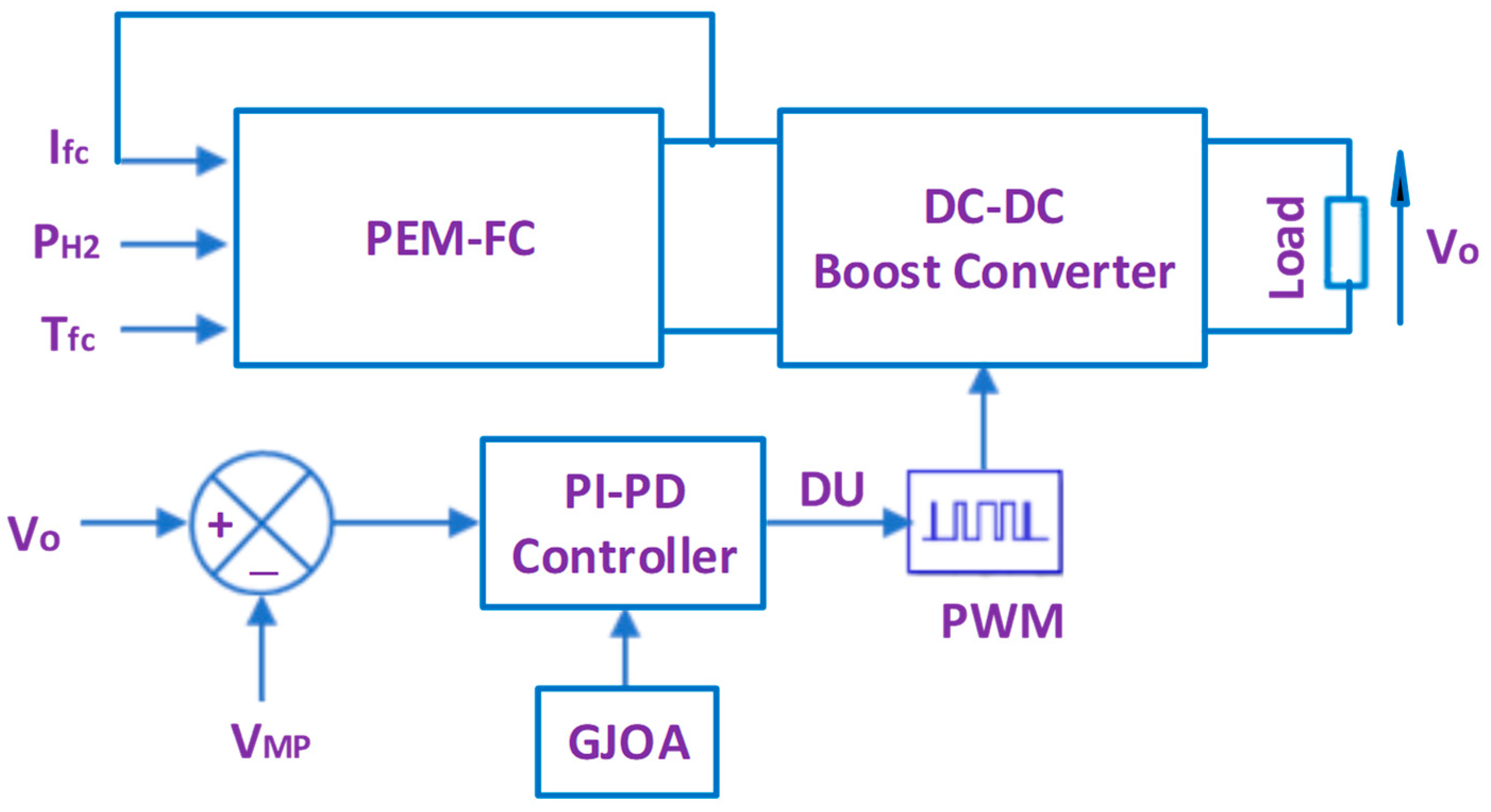
2]. Because of the merits of the proton exchange membrane fuel cell (PEM-FC), it is favored over other types of FC. The optimum operation of PEM-FC is investigated in this article.
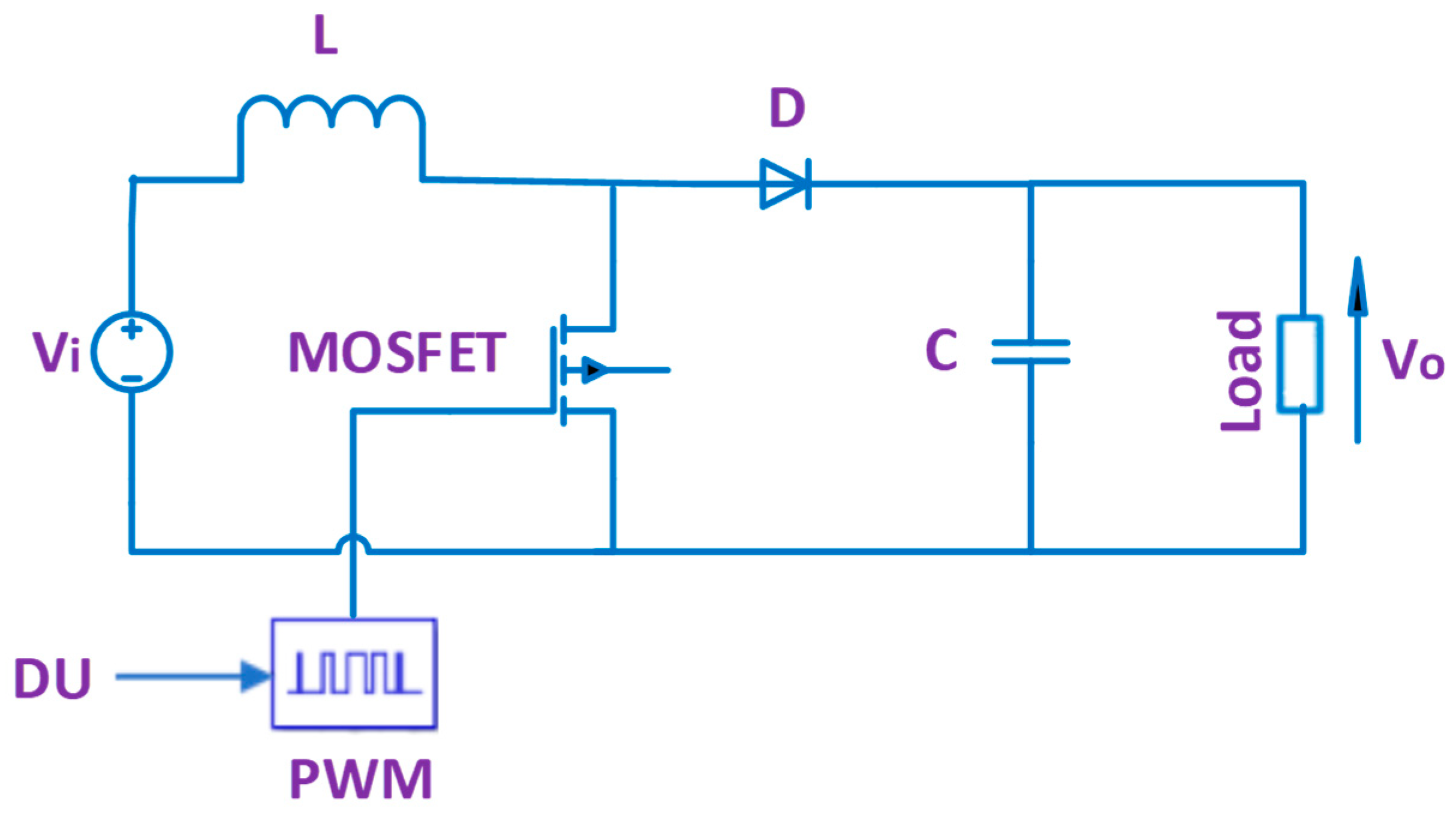
For each group of operation conditions for PEM-FC, i.e., hydrogen pressure, cell temperature, and electric load, there exists a unique point on the current–power (I/P) plot representing maximum power. Accordingly, the maximum power point tracking (MPPT) procedure is required for extraction of the maximum power from the PEM-FC at various operation conditions. The MPPT system is a DC-DC boost converter with an adjustable duty switch cycle (DU). The DC-DC boost converter is fed via the stack terminal voltage (Vsta) of PEM-FC and DU is adjusted to make the output voltage (Vo) track the voltage at MPP (VMP). The difference between the various approaches to MPPT by PEM-FC is the determination method of VMP for adjustment of DU via the DC-DC boost converter.
In this regard, perturb and observe (P&O) [12,13] has been utilized for MPPT of PEM-FC, where Vo is repeatedly varied via varying DU by a fixed step (ΔDU), the resultant power and voltage variations are observed and, accordingly, DU is increased or decreased in the next variation until reaching MPP. The authors of [14] have utilized fuzzy logic (FL) to determine ΔDU size of P&O. In the incremental conductance (IC) [15] and the incremental resistance (IR) [16] methods, VMP is determined wherever the derivative of power of the PEM-FC stack with regards to the operating current of the FC () equals zero. The authors of [17,18] have employed a backstepping technique to determine DU, which makes IFC track the current at MPP. In the prementioned methods, the power of PEM-FC is calculated via multiplying the measured values of Vo and IFC while, in the variable step size (VSS) [19,20,21], the measured value of IFC is only utilized to decrease the cost and complexity.
In [22,23,24,25], Vsta and IFC are entered into the trained artificial neural network (ANN) to produce the DU of the DC-DC boost converter. Adaptive ANN based on a fuzzy inference system has been applied in [26,27,28].
The authors of [29,30,31] have employed FL for determination of DU of the DC-DC boost converter for MPPT of PEM-FC. In the same regard, several controllers have been employed, such as model predictive control (MPC) [32], sliding mode controller (SMC) [33,34,35], fuzzy logic controller (FLC) [36,37,38,39,40], FLC-based VSS [41,42,43], and FLC optimized by various algorithms, e.g., firefly optimizer [44] and differential evolution (DE) [45].
In addition to the aforementioned controllers, numerous others have been employed for MPPT of PEM-FC, i.e., the proportional-integral-derivative (PID) controller optimized by numerous algorithms, such as salp swarm approach (SSA) [46], the particle swarm optimizer(PSO) [47], the grey wolf optimizer (GWO) [48], the fractional-order PID controller optimized by forensic-based investigation optimizer [49], and the fractional-order integral controller with filter [50].
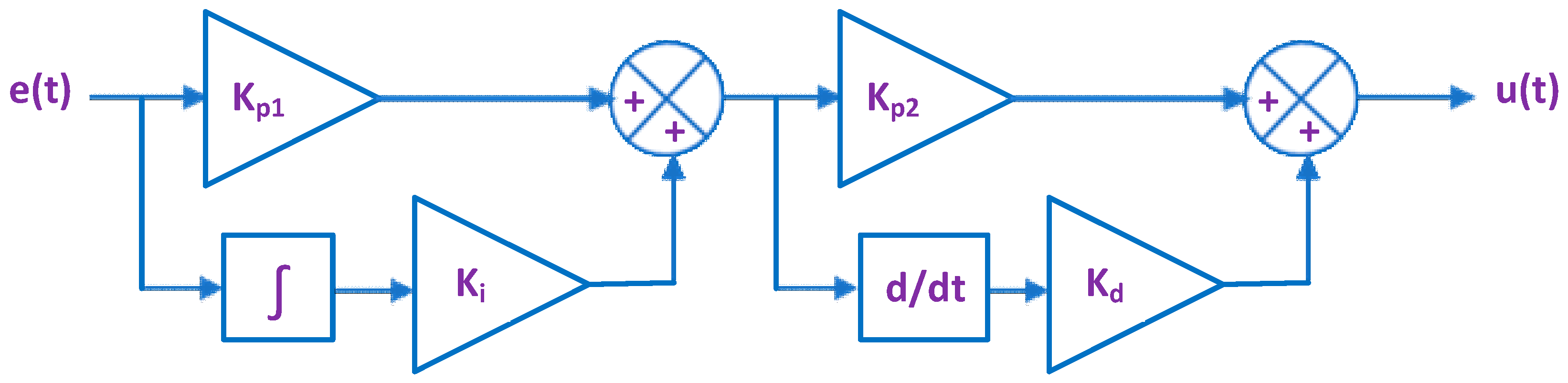
Table 1 summarizes the limitations of many published techniques. This article addresses the deficiencies of the former published works by proposing an innovative PI-PD controller for MPPT of PEM-FC. The gains of the PI-PD controller are adjusted through the golden jackal optimization algorithm (GJOA). The suggested approach (GJOA-PI-PD) and controller has the potential for improving results, since its structure (PI-PD controller) is different from those in the literature, i.e., the PID and FOPID controllers. Additionally, the results of applying the PI-PD controller for automatic generation control in [51] revealed its advantages over PID and PI controllers.
Table 1.
Brief of limitations of some techniques utilized for MPPT of PEM-FC.
Recently, metaheuristic optimization techniques have been applied for numerous purposes. Three kinds of these techniques are employed: evolutionary algorithms, physics-based, and swarm intelligence techniques. The first kind is driven by relying on biological evolution, e.g., DE and artificial bee colony. The second kind is driven by relying on physical laws, e.g., equilibrium algorithm and Archimedes optimizer. The last kind is driven by relying on the manners of animal groups, e.g., PSO, SSA, and GWO.
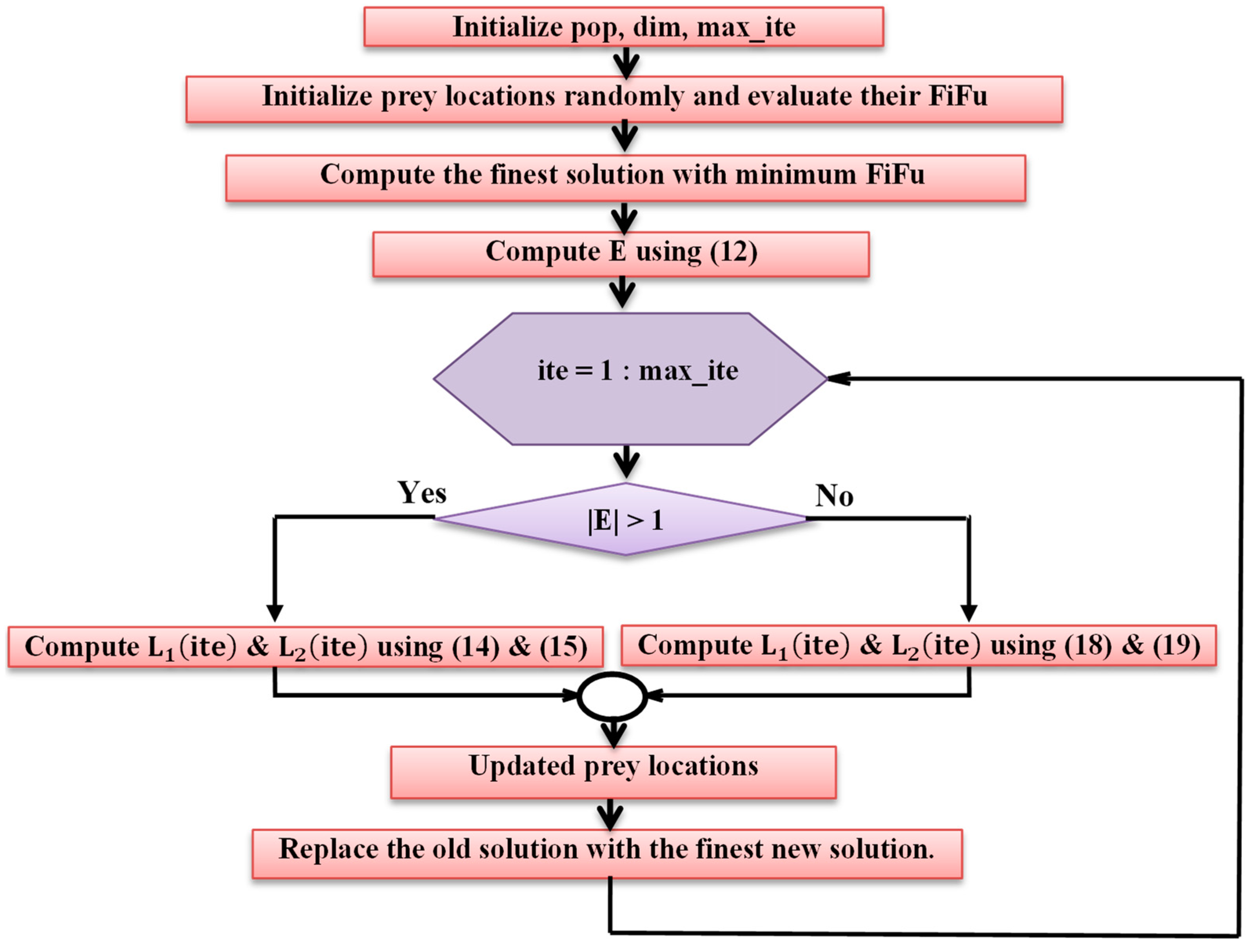
In this regard, the GJOA is suggested for adjusting the gains of the PI-PD controller. The GJOA is a metaheuristic optimizer that replicates the golden jackal’s manner during hunting [52]. GJOA was written in 2022 and utilized successfully for economic dispatch [52], planning of wind turbines, and for charging stations of electric vehicles [53]. The successful utilization of GJOA for engineering optimization issues encouraged the authors to employ it to adjust the gains of the PI-PD controller for MPPT of PEM-FC.
The contributions of this article are:
- The innovative employment of the PI-PD controller for MPPT of PEM-FC.
- The innovative application of GJOA for adjustment of the gains of the PI-PD controller.
- Comparing the acquired results using the GJOA-PI-PD controller for MPPT of PEM-FC with those based on the P&O approach, GJOA-PID, and GJOA-FOPID controllers in order to confirm its supremacy.
- The GJOA-PI-PD controller performance is validated through variations in hydrogen pressure, cell temperature, and electric load.
The remainder of the article is organized as follows: FCs are overviewed in Section 2. The PEM-FC is modeled in Section 3. The DC-DC boost converter is revealed in Section 4. The proposed control strategy of MPPT is clarified in Section 5, including the PI-PD controller and GJOA plus the compared control strategies i.e., FOPID controller and P&O. The results are discussed in Section 6. Conclusions are extracted in Section 7.
2. Overview of FCs
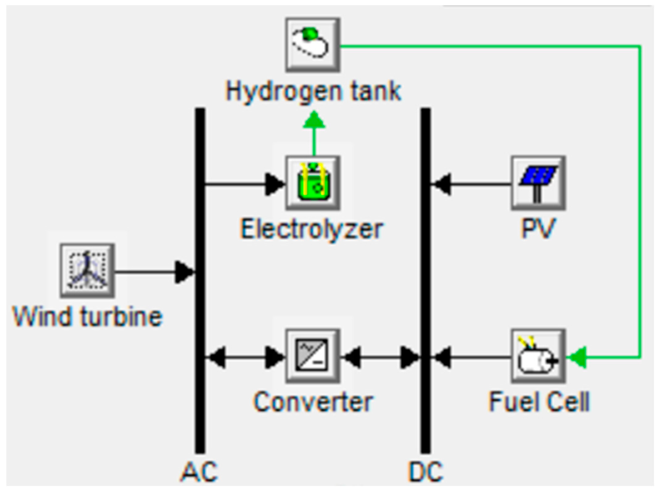
Figure 1 reveals the complete scheme of the FC utilized for electrochemical ES of REs. The water is distilled, then supplied to the electrolyzer by water pump. The electrolyzer produces one molecule of hydrogen (H2) from each molecule of water (H2O). The relationship between electrical power () and the volumetric hydrogen rate () (m3/h) is stated in (1) [54]:
where and are electrical, current, and voltaic efficiencies, respectively, is the hydrogen density (0.08988 kg/m3), e is the number of electrons implied in the reaction and equals 2 for water splitting, F is Faraday’s number (96,485 As/mol), is the reversible cell voltage, and is the relative molecular mass (2.016 g/mol). The reversible PEM fuel cells exhibited a round-trip electrical efficiency of 40–46% at current density of 500 mA/cm2. The energy conversion process inside is clean, since FC exhaust is water vapor.
Figure 1.
Complete scheme of FC utilized for electrochemical ES of REs.
FCs are mainly categorized according to their electrolyte. This categorization establishes the type of electrochemical reactions which occur inside the FC, the type of catalysts needed, the temperature limit of the FC, the fuel needed, and other features. These FC characteristics impact their appropriate purposes. The kinds of FC include proton exchange membrane fuel cell (PEM-FC), solid oxide FC, phosphoric acid FC, alkaline FC, molten FC, and direct methanol [55]. Comparison among kinds of FCs reveals that PEM-FC is distinguished by its low operating temperature, great power extent, rapid start-up, little corrosion, simple composition, light weight, small volume, cheap cost, and long life span [56]. Additionally, the solid electrolyte of PEM-FCs makes electrode sealing simpler than with other kinds of FC. The operating temperature of PEM-FC ranges between 60 and 100 °C. The entire expense of a car based on the PEM-FC is 500–600 $/kW [57]. Thus, PEM-FCs are employed in several applications for instance transportation [56], airplanes, and distributed generators [58].
3. PEM-FC Model
The PEM-FC stack model has been densely illustrated in the literature. For a stack composed of as a series connected cells, can be calculated as below [19,21]:
where E is open circuit potential, and are activation and concentration over-voltages for each cell, respectively, and is ohmic voltage drop for each cell. These variables are computed using (3) to (6) [19,21].
where is cell temperature , and and are partial pressures of and , respectively.
where are empirical parameters, is concentration of , and is the operating current of the FC.
where is parametric coefficient, and and are actual and maximum density of current , respectively.
where and are resistances of the membrane and connections, respectively.
is computed as below:
By reference to to , it is clear that is reliant on , , and which is reliant on electric load.
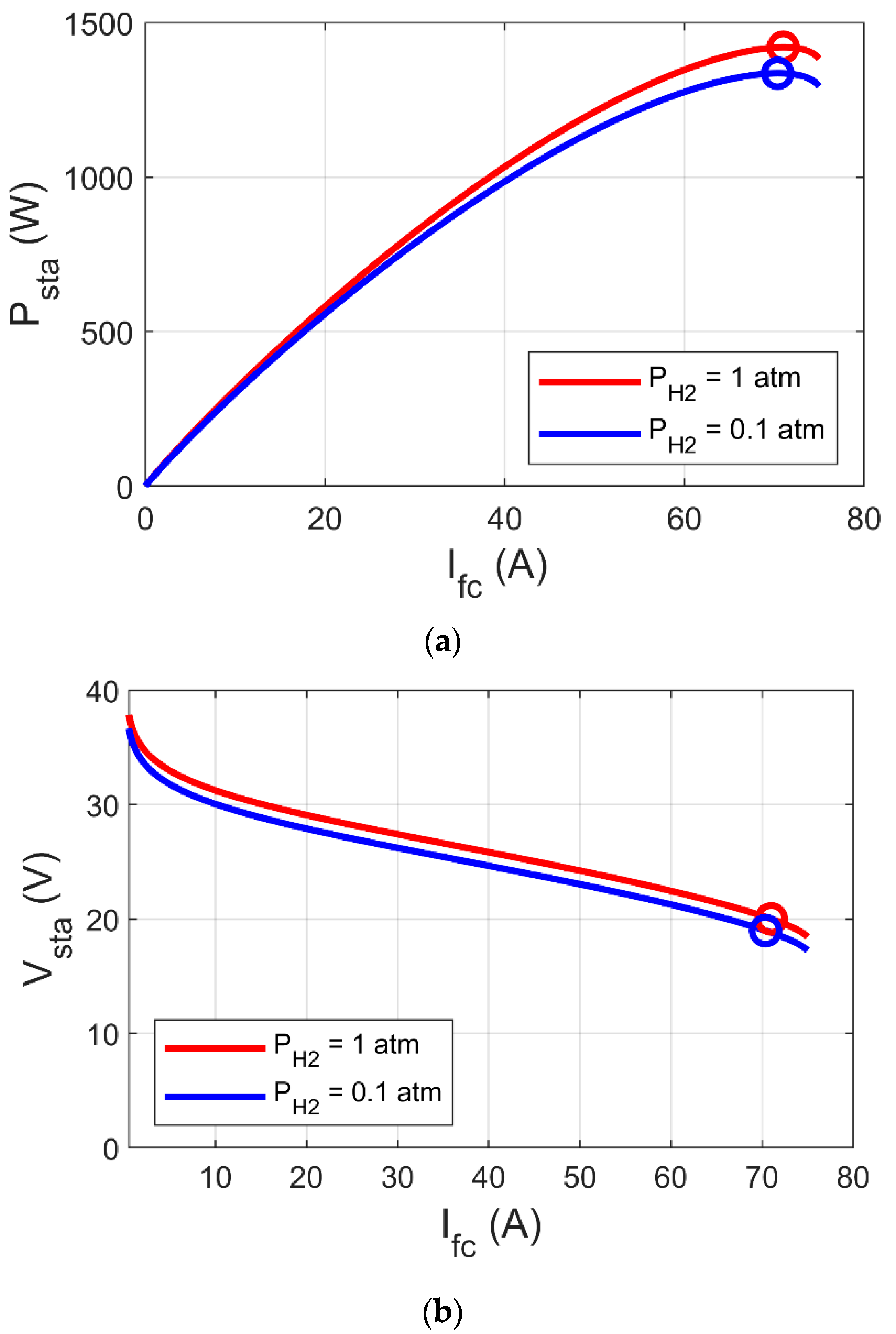
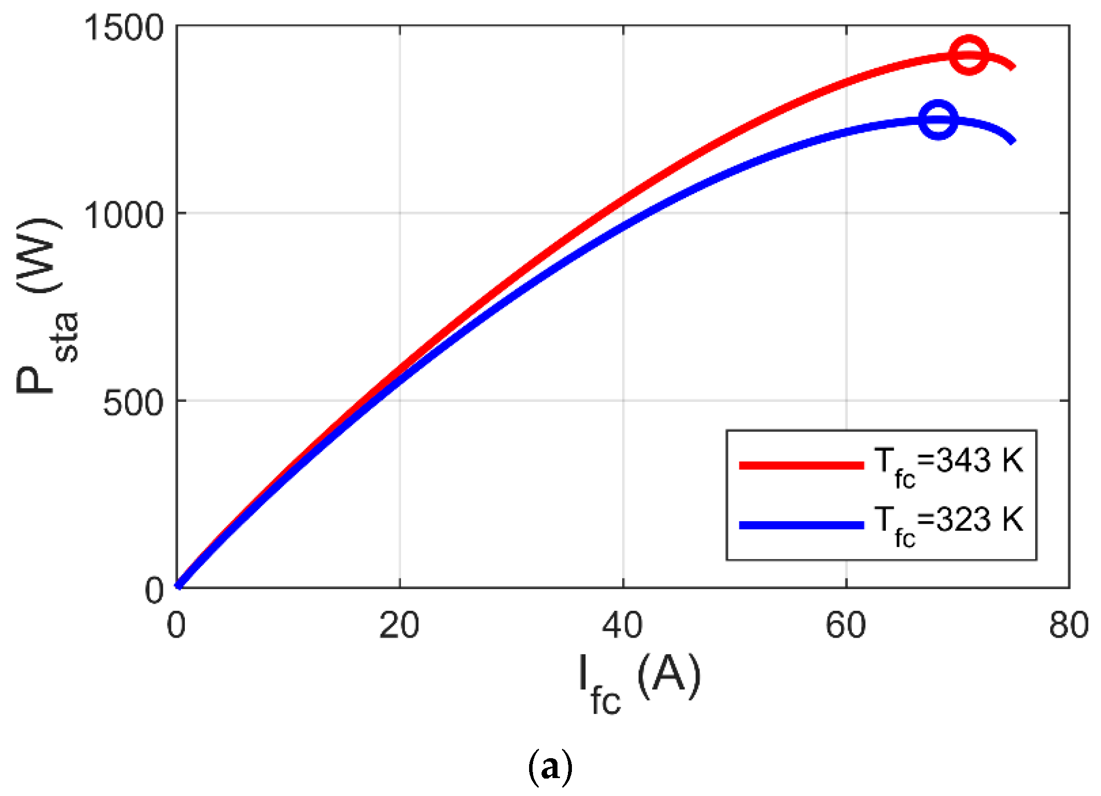
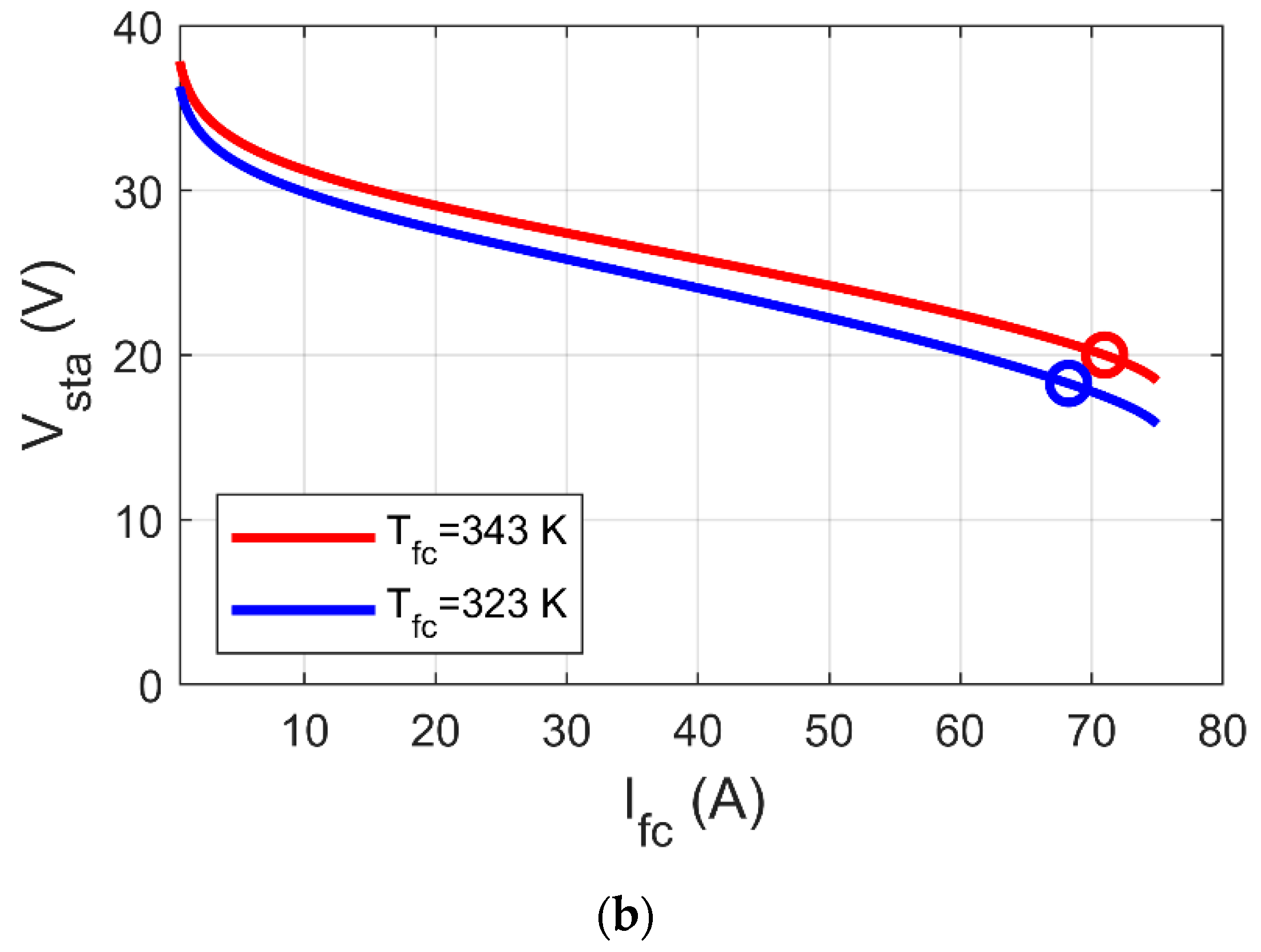
 Figure 2 and Figure 3 show the variation of MPP based on the variations of and , respectively, where MPP increases with increase of both and . In Figure 2b and Figure 3b, it can be observed that MPP occurs at a specific voltage (VMP), which is reliant on , , and electric load. Thus, the key to reach MPP is to raise Vfc to VMP using the DC-DC boost converter. In this article, we suggest an innovative MPPT for PEM-FC using the PI-PD controller, whose gains are tuned by GJOA. We begin with an explanation of the DC-DC boost converter in the next section.
Figure 2.
Impact of variations on MPP of PEM-FC. (a) I/P cs. (b) I/V cs.

Figure 3.
Impact of variations on MPP of PEM-FC. (a) I/P cs. (b) I/V cs.
4. DC-DC Boost Converter
Figure 4 reveals the DC-DC boost converter, comprised of an inductor (L) to store energy, MOSFET to switch on and off, a diode (D) to insulate between the input and output intervals, and a capacitor (C) to lessen ripples. Additionally, a pulse width modulator (PWM) supplies pulses to the gate of MOSFET [17,26,28,33,40,48]. The width of pulses is modulated depending on DU. The number of pulses per second is determined via switching frequency (fswi) of PWM.
Figure 4.
DC-DC boost converter.
Vo is dependent on input voltage (Vi) and DU as stated in (8) [17,26,28,33,40,48].
For known values of Vi and Vo, the value of DU can be derived from (8) as below:
When the DC-DC boost converter is employed for MPPT of PEM-FC, Vsta and VMP represent Vi and Vo, respectively. Since Vsta and VMP change continuously, then DU needs to be adjusted continuously. The suggested control strategy for adjusting the DU of the DC-DC boost converter for MPPT of PEM-FC is illustrated in the next section.
5. MPPT Control Strategy
Figure 5 reveals the schematic diagram of the suggested control scheme for MPPT of the PEM-FC, where DU of the DC-DC boost converter is tuned using a PI-PD controller whose gains are tuned using GJOA. The input of the PI-PD controller is the difference between VMP and Vo in order to make Vo track VMP continuously, and then tracks MPP continuously. The details of the PI-PD controller, GJOA, and fitness function (FiFu) of the GJOA are illustrated in Section 5.1, Section 5.2 and Section 5.3, respectively. Afterwards the compared approaches, i.e., FOPID controller and P&O, are illustrated in Section 5.4 and Section 5.5, respectively.
Figure 5.
Schematic diagram of the suggested MPPT control scheme.
5.1. PI-PD Controller
Figure 6 reveals that the PI-PD controller is a consecutive controller made up of PI and PD controllers whose gains are , , , and , respectively. The mathematical relationship between the output control signal (u(t)) and the input error signal (e(t)) of the PI-PD controller is stated in (10).
Figure 6.
PI-PD controller.
5.2. GJOA
The GJOA is a swarm intelligence optimizer which imitates the hunting manner of golden jackals in wildlife. Their hunting group consists of females and males. There are three stages in their hunting manner: 1—seeking and approaching the prey; 2—surrounding and confusing the prey, stopping its movement; 3—swooping on the prey.
Throughout the initialization step, a group of prey locations matrix () is produced randomly using (11) [52].
where pop symbolizes the population of the prey and dim symbolizes dimension.
E is the escaping energy of the prey and is computed using (11) [53].
where and indicate the diminishing energy of the prey and the initial energy, respectively. Value of ranges from [−1, 1], while the value of is computed via (13) [52].
where represents a fixed number, whose value is 1.5, represents the current iteration, and represents maximum number of iterations.
If , golden jackal hunting is mathematically modelled using (14) and (15) [53]:
where and are the updated locations of the male and female jackals, respectively, and symbolize the locations of the male and the female jackals, respectively, symbolizes the vector of numbers calculated randomly via the Levy flight function, symbolizes the vector of prey locations, represents the spacing among the prey and the jackal, and rl symbolizes a vector of numbers calculated randomly via the Levy flight function as stated in (16) and (17) [52].
where u and v are randomly determined values between 0 and 1 and β symbolizes a fixed number whose value is 1.5.
As the prey is fatigued due to the chase, E is diminished and meanwhile, when , the jackals surrounding the prey and gobbling it up are mathematically modelled using (18) and (19) [53]:
The updated location of the prey is computed via the average of and as stated in (20) [52].
All details of the GJOA can be found in [52]. The MATLAB code of GJOA can be found in [59]. Figure 7 reveals the flowchart of GJOA.
Figure 7.
Flowchart of GJOA.
5.3. Formularization of FiFu
In this subsection, we formulate the FiFu to be minimized by GJOA while tuning the gains of PI-PD controller, which in turn adjusts the DU of the DC-DC boost converter for MPPT of PEM-FC.
The main aim of MPPT of PEM-FC is to make Psta track quickly with minimal oscillations and overshoot, throughout the variations in , , or load. To achieve this, the DC-DC boost converter is utilized to make track as rapidly as possible. The requirements mentioned are guaranteed using the integral-time-absolute errors (ITAE) of as a superior criterion compared to other criteria, such as integral absolute error, integral square error, and integral time square error, as proven in [60]. Minimization of ITAE results in decrease of response time, overshoot, and oscillations, hence FiFu is proposed to minimize the ITAE, as stated below [60]:
where symbolizes the simulation time. The FiFu is subjugated via constraints to maintain the gains of the PI-PD controller within predefined limits.
5.4. FOPID Controller
The FOPID controller differs from the PID controller in that the order of both integration and differentiation is a fraction instead of an integer. The transfer function of the FOPID controller is stated in (22) [49].
where , , and symbolize the gains of FOPID controller and λ and µ symbolize the order of integration and differentiation, respectively.
5.5. P&O
P&O is an iterative approach for MPPT of PEM-FC. P&O is commonly utilized for its simplicity. Firstly, Vo and IFC are measured and Psta is calculated via multiplying their values, then DU is changed by fixed ΔDU, which leads to a change in Vo and, accordingly, Psta. The resultant changes in Psta (ΔPsta) and Vo (ΔVo) are monitored. If ΔPsta and ΔVo have the same sign, then DU is decreased by ΔDU, otherwise DU is increased by ΔDU in the next iteration. This procedure is repeated until ΔPsta equals zero, i.e., it reaches MPP. Figure 8 reveals the flow chart of the P&O approach [13].
Figure 8.
Flowchart of P&O.
6. Results with Discussion
The efficacy and forcefulness of MPPT of PEM-FC based on the GJOA-PI-PD controller are endorsed via comparing its results with those of other approaches. The impact of variations in , , and loading on the performance of the suggested MPPT of PEM-FC is also examined.
The simulation results have been obtained via MATLAB-R2021 in Windows 11.
The GJOA is operated with these parameters: pop = 10 and max_ite = 5. The MPPT is performed on a commercial typical PEM-FC, namely the Ballard Mark V, whose parameters are listed in Table 2. These parameter values were extracted using the whale optimizer in [61]. Regarding the values of parameters of the DC-DC boost converter, fswi = 10 kHz, high fswi is chosen to downsize the capacitors and inductors, which causes a cost decrease, L = 69 mH, and C = 1500 μF. These settings of L and C are carefully selected to assure low ripples in Vo at the indicated fswi. The limits within which the parameters of GJOA-PID, GJOA-FOPID, and GJOA-PI-PD controllers are maintained during minimization of FiFu using GJOA are listed in Table 3, Table 4 and Table 5, respectively. 
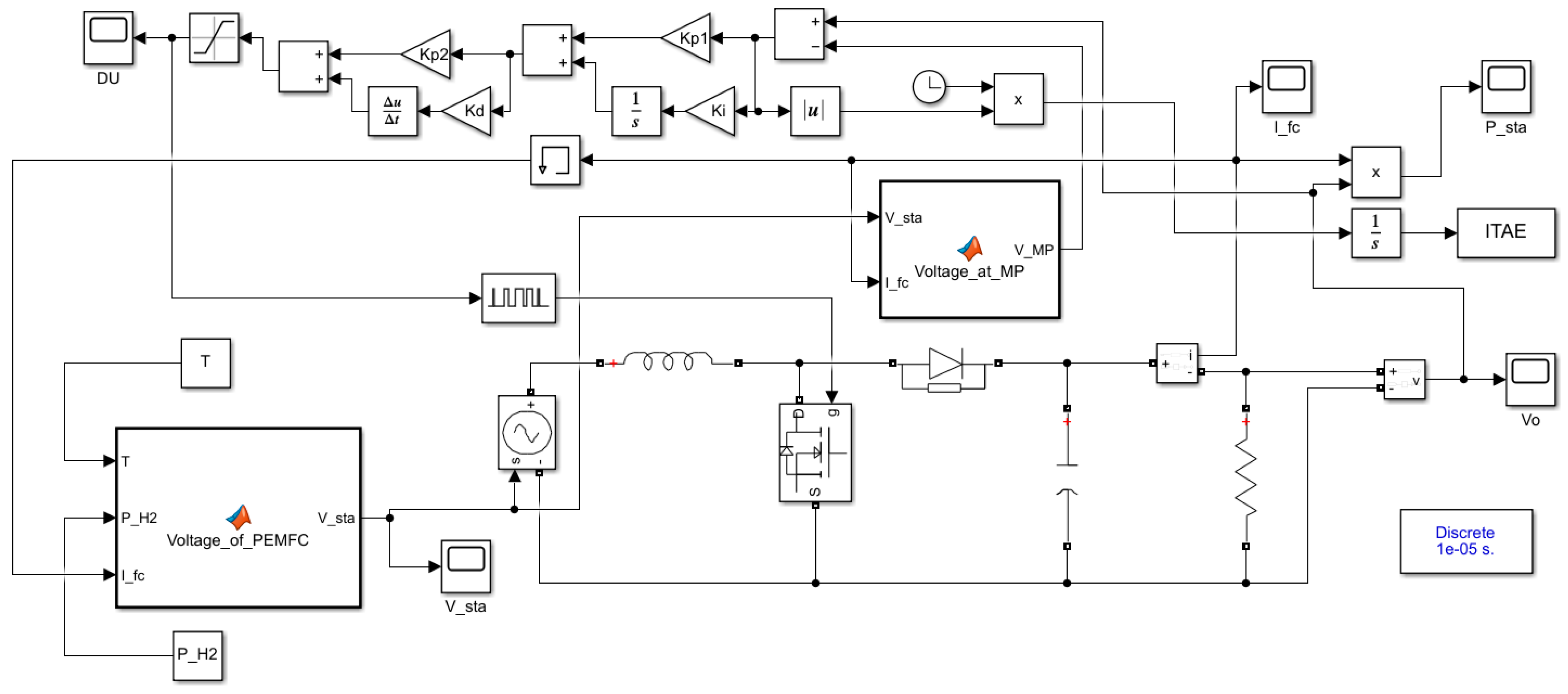
Figure 9 reveals the MATLAB Simulink model of the suggested MPPT for PEM-FC.
Table 2.
Parameters of Ballard Mark V.
Table 3.
The bounds of GJOA-PID controller parameters.
Table 4.
The bounds of GJOA-FOPID controller parameters.
Table 5.
The bounds of GJOA-PI-PD controller parameters.
Figure 9.
Simulink model of the suggested MPPT for PEM-FC.
6.1. MPPT of PEM-FC under Normal Operating Conditions
Normal operating conditions of and for the Ballard Mark V PEM-FC are applied in this case for different schemes of MPPT of PEM-FC. In detail, and . Regarding the electric load, resistance (R) of 50 Ω is supplied by PEM-FC.
The values of optimized parameters of GJOA-PID, GJOA-FOPID, and GJOA-PI-PD controllers are listed in Table 6, Table 7 and Table 8, respectively.
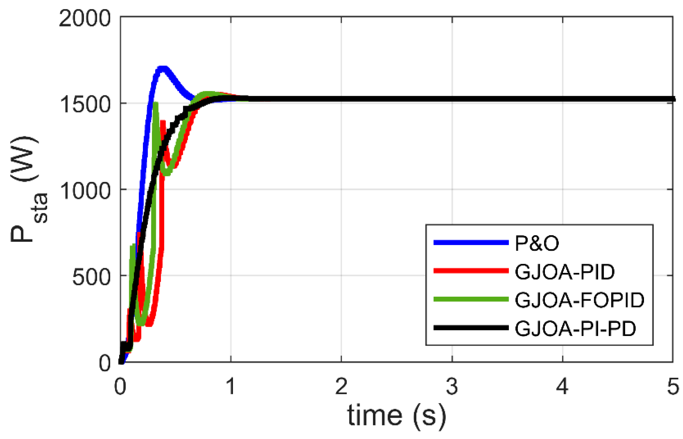
Table 6.
The optimized values of GJOA-PID controller parameters.
Table 7.
The optimized values of GJOA-FOPID controller parameters.
Table 8.
The optimized values of GJOA-PI-PD controller parameters.
Figure 10 reveals Psta of the Ballard Mark V PEM-FC when three MPPT schemes, plus the proposed scheme, are applied. Specifically, the P&O approach, GJOA-PID, and GJOA-FOPID controllers are compared with the proposed GJOA-PI-PD controller. High overshoot exists in the response of Psta when the P&O scheme is employed. There are oscillations and slowness in the response of Psta when GJOA-PID, and GJOA-FOPID controllers are employed. The resultant values of rise time (tr) and percentage overshoot (POS) for various MPPT schemes are listed in Table 9. The proposed GJOA-PI-PD controller results in POS of 0.2% which is the lowest overshoot compared to other MPPT schemes i.e., the P&O approach, GJOA-PID, and GJOA-FOPID controllers, by 98.26%, 86.30%, and 89.07%, respectively. The resultant value of tr with the proposed GJOA-PI-PD controller is 0.391 s, which is less than that of the GJOA-PID, and GJOA-FOPID controllers but more than that of P&O. The criteria in comparison are that the MPPT scheme, which has the quickest response, the least oscillations, and the lowest overshoot, is preferred over other schemes. When these criteria are applied to the results revealed in Table 8, the proposed GJOA-PI-PD controller is found to have better equilibrium among speed and overshoot than other MPPT schemes.
Figure 10.
Response of MPPT schemes for Ballard Mark V PEM-FC.
Table 9.
The optimized values of GJOA-FOPID controller parameters.
The previous comparison is based on visual analysis of the results. On the other hand, the comparison based on the numerical results of ITAE confirms the preference for the GJOA-PI-PD controller over other schemes, as summarized in Table 10, where the values of ITAE are listed. The value of ITAE resulting from the GJOA-PI-PD controller is the least compared to the others, by 93.95%, 87.17%, and 87.97%. It can be said that MPPT based on the GJOA-PI-PD controller outperforms other approaches by a wide margin. The MPPT schemes can be arranged in accordance with the smallness of ITAE as follows: GJOA-PI-PD, GJOA-PID, GJOA-FOPID controllers, then the P&O scheme.
Table 10.
The values of the resultant ITAE.
6.2. MPPT of PEM-FC under Variation of
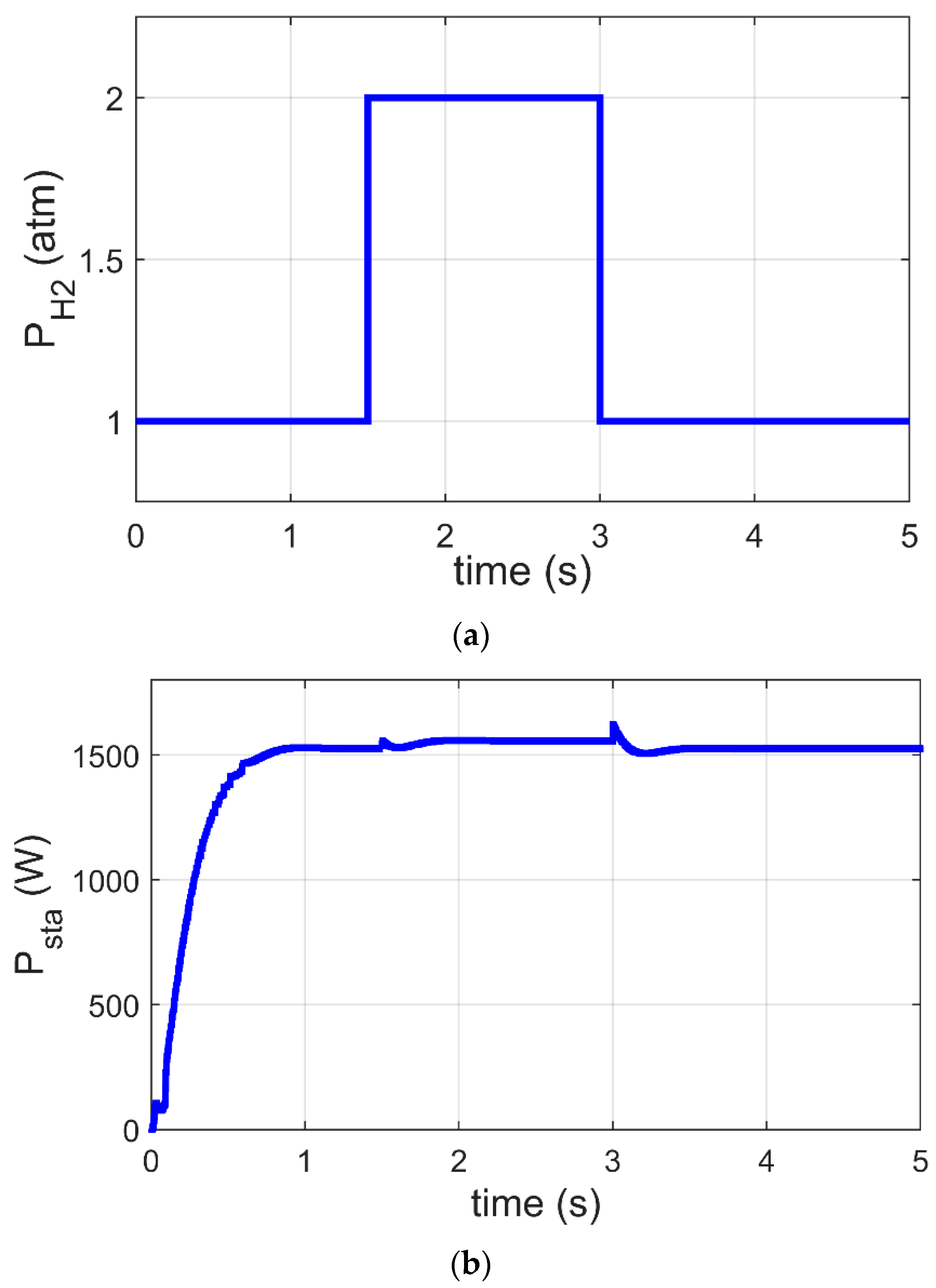
In this subsection, the GJOA-PI-PD controller for MPPT of the Ballard Mark V PEM-FC is validated when changes. Figure 11a reveals that the value of is initially 1 atm, then it increases to 2 atm at and afterward it decreases to 1 atm at . Figure 11b reveals the corresponding response of Psta during a change in where we observe that MPPT based on the GJOA-PI-PD controller reacts speedily to variation in . During the period of increase of , Psta increases to new value then decreases with decrease of . This means that Psta tracks the new MPP for new conditions. The new conditions in this case study resulted in a variation of from 1 atm to 2 atm and then from 2 atm to 1 atm, with constant values of and . Additionally, the absence of oscillations is observed. Furthermore, the values of overshoot and undershoot are very small.
Figure 11.
Response of MPPT based on GJOA-PI-PD controller at variation of . (a) Variation of . (b) Psta of Ballard Mark V PEM-FC.
6.3. MPPT of PEM-FC under Variation of
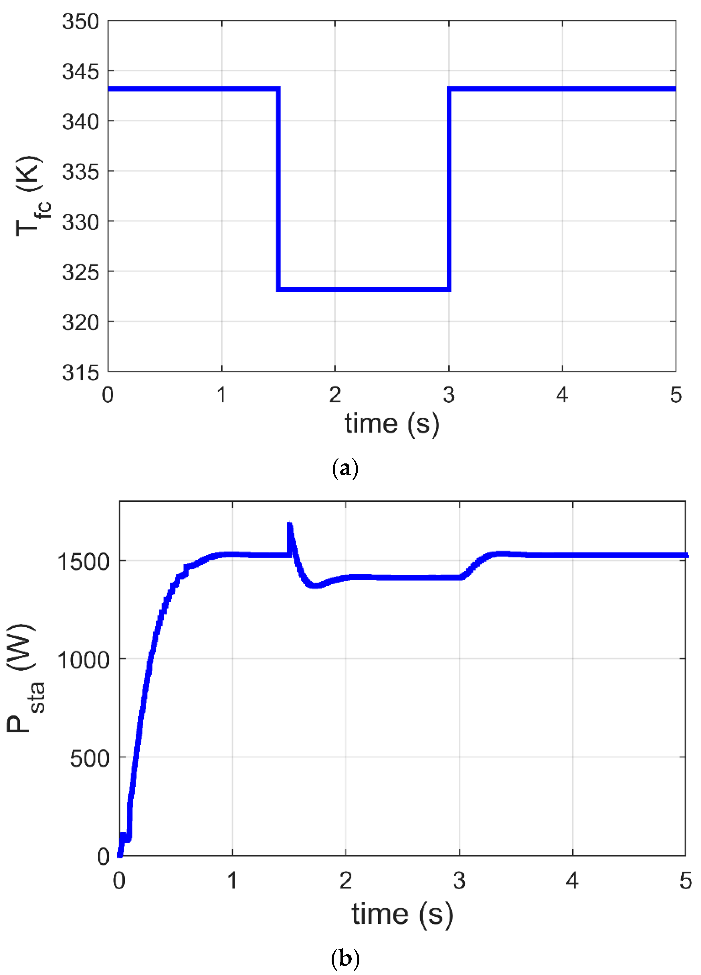
This part presents a justification for the GJOA-PI-PD controller for MPPT of the Ballard Mark V PEM-FC when varies. The change in is revealed in Figure 12a, where it is initially 343 K, then it decreases to 323 K at and after that it increases to 343 K at . The corresponding response of Psta during variation of is illustrated in Figure 12b, where the quick performance of MPPT based on the GJOA-PI-PD controller with variation of is observed. Throughout the period of decrease in , Psta decreases to its new value then increases with increase in . This indicates that Psta tracks new MPP for new conditions. The new conditions in this case study are caused by change in from 343 K to 323 K and then from 323 K to 343 K, with constant values of and . Moreover, there are no high values for oscillations during variation in Psta.
Figure 12.
Response of MPPT based on the GJOA-PI-PD controller at variation of . (a) Variation of . (b) Psta of Ballard Mark V PEM-FC.
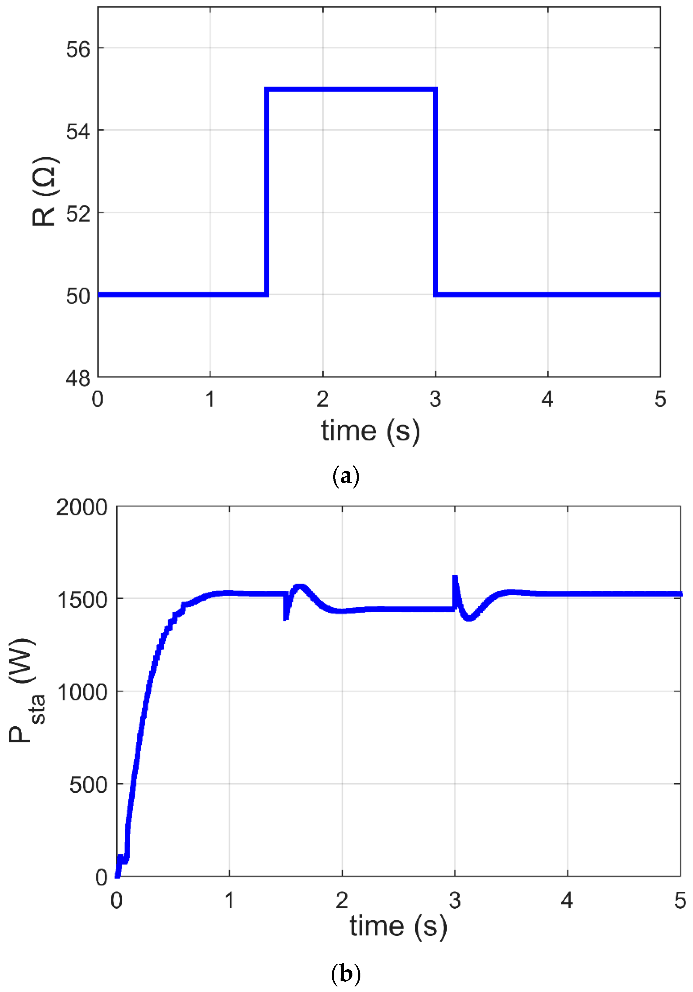
6.4. MPPT of PEM-FC under Variation of
In this subsection, the GJOA-PI-PD controller for MPPT of the Ballard Mark V PEM-FC is justified when changes. Figure 13a reveals that the value of is initially 50 Ω, then it increases to 55 Ω at and afterward decreases to 50 Ω at . Figure 13b reveals the corresponding response of Psta during change in where MPPT based on the GJOA-PI-PD controller responds quickly to variation in . During the period of increase in , Psta decreases to its new value then increases with decrease of . This points out that Psta tracks new MPP for new conditions. The new conditions in this case study result in variation of from 50 Ω to 55 Ω and then from 55 Ω to 50 Ω, with constant values of and . In addition, the oscillations are low.
Figure 13.
Response of MPPT based on GJOA-PI-PD controller with variation of . (a) Variation of . (b) Psta of Ballard Mark V PEM-FC.
7. Conclusions
The I/P plot of PEM-FC varies with the operating conditions, namely , , and loading. Accordingly, each group of conditions has a unique I/P plot with unique MPP. Therefore, the presence of the MPPT scheme is required to track MPP continuously. In this work, an innovative MPPT scheme for PEM-FC based on the PI-PD controller, whose gains are optimized via GJOA, has been suggested. The simulation results of the MPPT scheme based on the GJOA-PI-PD controller have been compared with those of other schemes, namely P&O, GJOA-PID, GJOA-FOPID controllers, at normal operating conditions of PEM-FC. The comparison has revealed that the ITAE which resulted using the MPPT scheme based on the GJOA-PI-PD controller is less than that of the compared schemes by 93.95%, 87.17%, and 87.97%, respectively. In addition, the simulation results have revealed that the response of the suggested scheme has the lowest oscillations and overshoot. Furthermore, the MPPT scheme based on the GJOA-PI-PD controller has been legitimized during variation in operating conditions. The simulation results of the MPPT scheme based on the GJOA-PI-PD controller during variation of , , and loading reveal the high speed of performance. Our research plan in the future is to experimentally legalize the suggested MPPT controller of PEM-FC.
Author Contributions
Conceptualization, A.M.A.; methodology, A.M.A.; software, A.M.A.; validation, A.M.A.; formal analysis, A.M.A.; investigation, T.I.A. and H.K.; resources, E.T. and D.K.A.; data curation, A.M.A.; writing—original draft preparation, A.M.A.; writing—review and editing, T.I.A. and E.T.; visualization, H.K. and A.A.; supervision, E.T. and T.I.A.; project administration, H.K. and A.A.; funding acquisition, A.A. and D.K.A. All authors have read and agreed to the published version of the manuscript.
Funding
This research was funded by the Deanship of Scientific Research at Northern Border University for funding this work through research group no. (RG-NBU-2022-1215).
Institutional Review Board Statement
Not applicable.
Data Availability Statement
Not applicable.
Acknowledgments
The authors extend their appreciation to the Deanship of Scientific Research at Northern Border University for funding this work through research group no. (RG-NBU-2022-1215). The authors gratefully thank the Prince Faisal bin Khalid bin Sultan Research Chair in Renewable Energy Studies and Applications (PFCRE) at Northern Border University for their support and assistance.
Conflicts of Interest
The authors declare no conflict of interest.
References
- Nasser, M.; Hassan, H. Assessment of standalone streetlighting energy storage systems based on hydrogen of hybrid PV/electrolyzer/fuel cell/desalination and PV/batteries. J. Energy Storage 2023, 63, 106985. [Google Scholar] [CrossRef]
- Dodón, A.; Quintero, V.; Austin, M.C.; Mora, D. Bio-Inspired Electricity Storage Alternatives to Support Massive Demand-Side Energy Generation: A Review of Applications at Building Scale. Biomimetics 2021, 6, 51. [Google Scholar] [CrossRef]
- Calati, M.; Hooman, K.; Mancin, S. Thermal storage based on phase change materials (PCMs) for refrigerated transport and distribution applications along the cold chain: A review. Int. J. Thermofluids 2022, 16, 100224. [Google Scholar] [CrossRef]
- You, J.; Wang, C.; Ma, L.; Yin, S. Safe energy-storage mechanical metamaterials via architecture design. EPJ Appl. Metamater. 2023, 10, 1–7. [Google Scholar] [CrossRef]
- Hasan, M.; Uddin, M.; Nasrin, R. Exothermic chemical reaction of magneto-convective nanofluid flow in a square cavity. Int. J. Thermofluids 2022, 16, 100236. [Google Scholar] [CrossRef]
- Miller, M.A.; Petrasch, J.; Randhir, K.; Rahmatian, N.; Klausner, J. Chemical Energy Storage; Elsevier: Amsterdam, The Netherlands, 2020; pp. 249–292. [Google Scholar] [CrossRef]
- Tawalbeh, M.; Murtaza, S.Z.; Al-Othman, A.; Alami, A.H.; Singh, K.; Olabi, A.G. Ammonia: A versatile candidate for the use in energy storage systems. Renew. Energy 2022, 194, 955–977. [Google Scholar] [CrossRef]
- Tawalbeh, M.; Khan, H.A.; Al-Othman, A. Insights on the applications of metal oxide nanosheets in energy storage systems. J. Energy Storage 2023, 60, 106656. [Google Scholar] [CrossRef]
- Ulu, G.; Semerciöz, A.S.; Özilgen, M. Energy storage and reuse in biological systems: Case studies. Energy Storage 2021, 3, e253. [Google Scholar] [CrossRef]
- Tawalbeh, M.; Khan, H.A.; Al-Othman, A.; Almomani, F.; Ajith, S. A comprehensive review on the recent advances in materials for thermal energy storage applications. Int. J. Thermofluids 2023, 18, 100326. [Google Scholar] [CrossRef]
- Guo, Y.; Yousefi, A. Determining the appropriate size of the electrical energy storage system of an energy process based on a solid oxide fuel cell and wind turbine. J. Energy Storage 2021, 44, 103430. [Google Scholar] [CrossRef]
- Naseri, N.; El Hani, S.; Aghmadi, A.; El Harouri, K.; Heyine, M.S.; Mediouni, H. Proton Exchange Membrane Fuel Cell Modelling and Power Control by P&O Algorithm. In Proceedings of the 2018 6th International Renewable and Sustainable Energy Conference (IRSEC 2018), Rabat, Morocco, 5–8 December 2018; pp. 1–5. [Google Scholar] [CrossRef]
- Karthikeyan, V.; Das, P.V.; Blaabjerg, F. Implementation of MPPT Control in Fuel Cell Fed High Step Up Ratio DC-DC Converter. In Proceedings of the 2018 2nd IEEE International Conference on Power Electronics, Intelligent Control and Energy Systems (ICPEICES 2018), Delhi, India, 22–24 October 2018; pp. 689–693. [Google Scholar] [CrossRef]
- Harrag, A.; Rezk, H. Indirect P&O type-2 fuzzy-based adaptive step MPPT for proton exchange membrane fuel cell. Neural Comput. Appl. 2021, 33, 9649–9662. [Google Scholar] [CrossRef]
- Karami, N.; El Khoury, L.; Khoury, G.; Moubayed, N. Comparative study between P&O and incremental conductance for fuel cell MPPT. In Proceedings of the 2014 International Conference on Renewable Energies for Developing Countries (REDEC 2014), Beirut, Lebanon, 26–27 November 2014; pp. 17–22. [Google Scholar] [CrossRef]
- Rezk, H. Performance of incremental resistance MPPT based proton exchange membrane fuel cell power system. In Proceedings of the 2016 18th International Middle-East Power Systems Conference (MEPCON 2016), Cairo, Egypt, 27–29 December 2016; pp. 199–205. [Google Scholar] [CrossRef]
- Derbeli, M.; Barambones, O.; Sbita, L. A Robust Maximum Power Point Tracking Control Method for a PEM Fuel Cell Power System. Appl. Sci. 2018, 8, 2449. [Google Scholar] [CrossRef]
- Derbeli, M.; Barambones, O.; Silaa, M.Y.; Napole, C. Real-Time Implementation of a New MPPT Control Method for a DC-DC Boost Converter Used in a PEM Fuel Cell Power System. Actuators 2020, 9, 105. [Google Scholar] [CrossRef]
- Harrag, A.; Bahri, H. A Novel Single Sensor Variable Step Size Maximum Power Point Tracking for Proton Exchange Membrane Fuel Cell Power System. Fuel Cells 2019, 19, 177–189. [Google Scholar] [CrossRef]
- Rezk, H.; Fathy, A. Performance Improvement of PEM Fuel Cell Using Variable Step-Size Incremental Resistance MPPT Technique. Sustainability 2020, 12, 5601. [Google Scholar] [CrossRef]
- Harrag, A.; Messalti, S. Variable Step Size IC MPPT Controller for PEMFC Power System Improving Static and Dynamic Performances. Fuel Cells 2017, 17, 816–824. [Google Scholar] [CrossRef]
- Reddy, K.J.; Sudhakar, N. High Voltage Gain Interleaved Boost Converter with Neural Network Based MPPT Controller for Fuel Cell Based Electric Vehicle Applications. IEEE Access 2018, 6, 3899–3908. [Google Scholar] [CrossRef]
- Reddy, K.J.; Sudhakar, N. A new RBFN based MPPT controller for grid-connected PEMFC system with high step-up three-phase IBC. Int. J. Hydrogen Energy 2018, 43, 17835–17848. [Google Scholar] [CrossRef]
- Derbeli, M.; Napole, C.; Barambones, O. Machine Learning Approach for Modeling and Control of a Commercial Heliocentris FC50 PEM Fuel Cell System. Mathematics 2021, 9, 2068. [Google Scholar] [CrossRef]
- Harrag, A.; Bahri, H. Novel neural network IC-based variable step size fuel cell MPPT controller. Int. J. Hydrogen Energy 2017, 42, 3549–3563. [Google Scholar] [CrossRef]
- Reddy, K.J.; Sudhakar, N. ANFIS-MPPT control algorithm for a PEMFC system used in electric vehicle applications. Int. J. Hydrogen Energy 2019, 44, 15355–15369. [Google Scholar] [CrossRef]
- Raj, A.; Lekhaj, P. An ANFIS Based MPPT Controller for Fuel Cell Powered Induction Motor Drive. In Proceedings of the 2018 International Conference on Smart Grid and Clean Energy Technologies (ICSGCE 2018), Kajang, Malaysia, 9 May–1 June 2018; pp. 201–205. [Google Scholar] [CrossRef]
- Ashraf, H.; Elkholy, M.M.; Abdellatif, S.O.; El-Fergany, A.A. Synergy of neuro-fuzzy controller and tuna swarm algorithm for maximizing the overall efficiency of PEM fuel cells stack including dynamic performance. Energy Convers. Manag. X 2022, 16, 100301. [Google Scholar] [CrossRef]
- Luta, D.N.; Raji, A.K. Comparing fuzzy rule-based MPPT techniques for fuel cell stack applications. Energy Procedia 2019, 156, 177–182. [Google Scholar] [CrossRef]
- Gheisarnejad, M.; Boudjadar, J.; Khooban, M.-H. A New Adaptive Type-II Fuzzy-Based Deep Reinforcement Learning Control: Fuel Cell Air-Feed Sensors Control. IEEE Sens. J. 2019, 19, 9081–9089. [Google Scholar] [CrossRef]
- Aliasghary, M. Control of PEM Fuel Cell Systems Using Interval Type-2 Fuzzy PID Approach. Fuel Cells 2018, 18, 449–456. [Google Scholar] [CrossRef]
- Derbeli, M.; Charaabi, A.; Barambones, O.; Napole, C. High-Performance Tracking for Proton Exchange Membrane Fuel Cell System PEMFC Using Model Predictive Control. Mathematics 2021, 9, 1158. [Google Scholar] [CrossRef]
- Silaa, M.Y.; Derbeli, M.; Barambones, O.; Cheknane, A. Design and Implementation of High Order Sliding Mode Control for PEMFC Power System. Energies 2020, 13, 4317. [Google Scholar] [CrossRef]
- Derbeli, M.; Barambones, O.; Farhat, M.; Ramos-Hernanz, J.A.; Sbita, L. Robust high order sliding mode control for performance improvement of PEM fuel cell power systems. Int. J. Hydrogen Energy 2020, 45, 29222–29234. [Google Scholar] [CrossRef]
- Wang, M.H.; Huang, M.-L.; Jiang, W.-J.; Liou, K.-J. Maximum power point tracking control method for proton exchange membrane fuel cell. IET Renew. Power Gener. 2016, 10, 908–915. [Google Scholar] [CrossRef]
- Kart, S.; Demir, F.; Kocaarslan, İ.; Genc, N. Increasing PEM fuel cell performance via fuzzy-logic controlled cascaded DC-DC boost converter. Int. J. Hydrogen Energy 2023. [Google Scholar] [CrossRef]
- Hai, T.; Alazzawi, A.K.; Zhou, J.; Farajian, H. Performance improvement of PEM fuel cell power system using fuzzy logic controller-based MPPT technique to extract the maximum power under various conditions. Int. J. Hydrogen Energy 2023, 48, 4430–4445. [Google Scholar] [CrossRef]
- Khan, M.J.; Mathew, L. Fuzzy logic controller-based MPPT for hybrid photo-voltaic/wind/fuel cell power system. Neural Comput. Appl. 2018, 31, 6331–6344. [Google Scholar] [CrossRef]
- Derbeli, M.; Sbita, L.; Farhat, M.; Barambones, O. Proton exchange membrane fuel cell—A smart drive algorithm. In Proceedings of the International Conference on Green Energy Conversion Systems (GECS 2017), Hammamet, Tunisia, 23–25 March 2017; pp. 1–5. [Google Scholar] [CrossRef]
- Aggad, F.; Allaoui, T.; Tamer, A.; Denai, M. Modeling, Design and Energy Management of a Residential Standalone Photovoltaic-Fuel Cell Power System. Prz. Elektrotechniczny 2020, 96, 79–87. [Google Scholar] [CrossRef]
- Harrabi, N.; Souissi, M.; Aitouche, A.; Chaabane, M. Modeling and control of photovoltaic and fuel cell based alternative power systems. Int. J. Hydrogen Energy 2018, 43, 11442–11451. [Google Scholar] [CrossRef]
- Harrag, A.; Messalti, S. How fuzzy logic can improve PEM fuel cell MPPT performances? Int. J. Hydrogen Energy 2018, 43, 537–550. [Google Scholar] [CrossRef]
- Abbaker, A.M.O.; Wang, H.; Tian, Y. Robust Model-Free Adaptive Interval Type-2 Fuzzy Sliding Mode Control for PEMFC System Using Disturbance Observer. Int. J. Fuzzy Syst. 2020, 22, 2188–2203. [Google Scholar] [CrossRef]
- Priyadarshi, N.; Sharma, A.K.; Azam, F. A Hybrid Firefly-Asymmetrical Fuzzy Logic Controller based MPPT for PV-Wind-Fuel Grid Integration. Int. J. Renew. Energy Res. 2017, 7, 1546–1560. [Google Scholar] [CrossRef]
- Aly, M.; Rezk, H. A Differential Evolution-Based Optimized Fuzzy Logic MPPT Method for Enhancing the Maximum Power Extraction of Proton Exchange Membrane Fuel Cells. IEEE Access 2020, 8, 172219–172232. [Google Scholar] [CrossRef]
- Fathy, A.; Abdelkareem, M.A.; Olabi, A.; Rezk, H. A novel strategy based on salp swarm algorithm for extracting the maximum power of proton exchange membrane fuel cell. Int. J. Hydrogen Energy 2020, 46, 6087–6099. [Google Scholar] [CrossRef]
- Ahmadi, S.; Abdi, S.; Kakavand, M. Maximum power point tracking of a proton exchange membrane fuel cell system using PSO-PID controller. Int. J. Hydrogen Energy 2017, 42, 20430–20443. [Google Scholar] [CrossRef]
- Rana, K.; Kumar, V.; Sehgal, N.; George, S. A Novel [Formula presented] feedback based control scheme using GWO tuned PID controller for efficient MPPT of PEM fuel cell. ISA Trans. 2019, 93, 312–324. [Google Scholar] [CrossRef] [PubMed]
- Fathy, A.; Rezk, H.; Alanazi, T.M. Recent Approach of Forensic-Based Investigation Algorithm for Optimizing Fractional Order PID-Based MPPT With Proton Exchange Membrane Fuel Cell. IEEE Access 2021, 9, 1–24. [Google Scholar] [CrossRef]
- Liu, J.; Zhao, T.; Chen, Y. Maximum power point tracking with fractional order high pass filter for proton exchange membrane fuel cell. IEEE/CAA J. Autom. Sin. 2017, 4, 70–71. [Google Scholar] [CrossRef]
- Agwa, A.M. Equilibrium optimization algorithm for automatic generation control of interconnected power systems. Prz. Elektrotechniczny 2020, 96, 145–150. [Google Scholar] [CrossRef]
- Chopra, N.; Ansari, M.M. Golden jackal optimization: A novel nature-inspired optimizer for engineering applications. Expert Syst. Appl. 2022, 198, 116924. [Google Scholar] [CrossRef]
- Yang, J.; Xiong, J.; Chen, Y.-L.; Yee, P.L.; Ku, C.S.; Babanezhad, M. Improved Golden Jackal Optimization for Optimal Allocation and Scheduling of Wind Turbine and Electric Vehicles Parking Lots in Electrical Distribution Network Using Rosenbrock’s Direct Rotation Strategy. Mathematics 2023, 11, 1415. [Google Scholar] [CrossRef]
- Korpås, M. Distributed Energy Systems with Wind Power and Energy Storage. Ph.D. Thesis, Norwegian University of Science and Technology, Trondheim, Norway, 2004. [Google Scholar]
- Hanif, M.B.; Motola, M.; Qayyum, S.; Rauf, S.; Khalid, A.; Li, C.-J.; Li, C.-X. Recent advancements, doping strategies and the future perspective of perovskite-based solid oxide fuel cells for energy conversion. Chem. Eng. J. 2021, 428, 132603. [Google Scholar] [CrossRef]
- Jakšić, Z.; Jakšić, O. Biomimetic Nanomembranes: An Overview. Biomimetics 2020, 5, 24. [Google Scholar] [CrossRef]
- Mekhilef, S.; Saidur, R.; Safari, A. Comparative study of different fuel cell technologies. Renew. Sustain. Energy Rev. 2012, 16, 981–989. [Google Scholar] [CrossRef]
- Zhang, Y.; Lv, Y.; Zhou, Y. Research on Economic Optimal Dispatching of Microgrid Based on an Improved Bacteria Foraging Optimization. Biomimetics 2023, 8, 150. [Google Scholar] [CrossRef]
- Golden Jackal Optimization Algorithm—File Exchange—MATLAB Central. Available online: https://www.mathworks.com/matlabcentral/fileexchange/108889-golden-jackal-optimization-algorithm?s_tid=ta_fx_results (accessed on 16 April 2023).
- Almabrok, A.; Psarakis, M.; Dounis, A. Fast Tuning of the PID Controller in An HVAC System Using the Big Bang–Big Crunch Algorithm and FPGA Technology. Algorithms 2018, 11, 146. [Google Scholar] [CrossRef]
- El-Fergany, A.A.; Hasanien, H.M.; Agwa, A.M. Semi-empirical PEM fuel cells model using whale optimization algorithm. Energy Convers. Manag. 2019, 201, 112197. [Google Scholar] [CrossRef]
Disclaimer/Publisher’s Note: The statements, opinions and data contained in all publications are solely those of the individual author(s) and contributor(s) and not of MDPI and/or the editor(s). MDPI and/or the editor(s) disclaim responsibility for any injury to people or property resulting from any ideas, methods, instructions or products referred to in the content. |
© 2023 by the authors. Licensee MDPI, Basel, Switzerland. This article is an open access article distributed under the terms and conditions of the Creative Commons Attribution (CC BY) license (https://creativecommons.org/licenses/by/4.0/).


