
A Numerical Study on the Crashworthiness of Corrugated Conical Tubes with Small Semi-Apical Angles and Their Influence Mechanism


Abstract
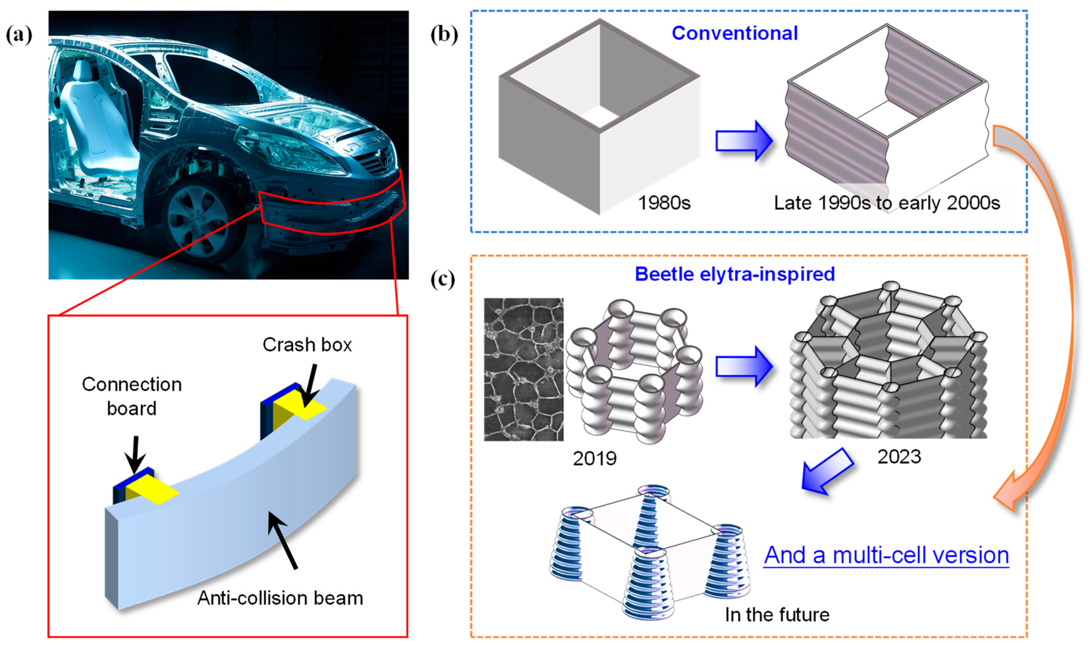
1. Introduction
2. Methods
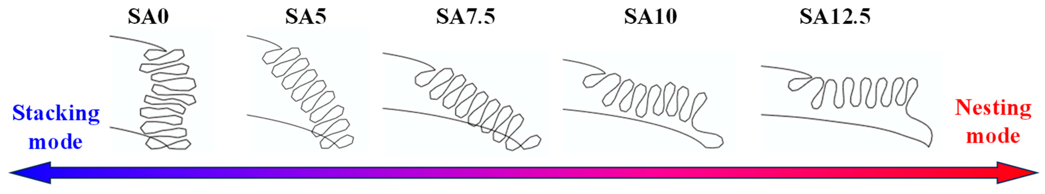
2.1. Design of CCTs
2.2. Indices for Evaluating Crashworthiness
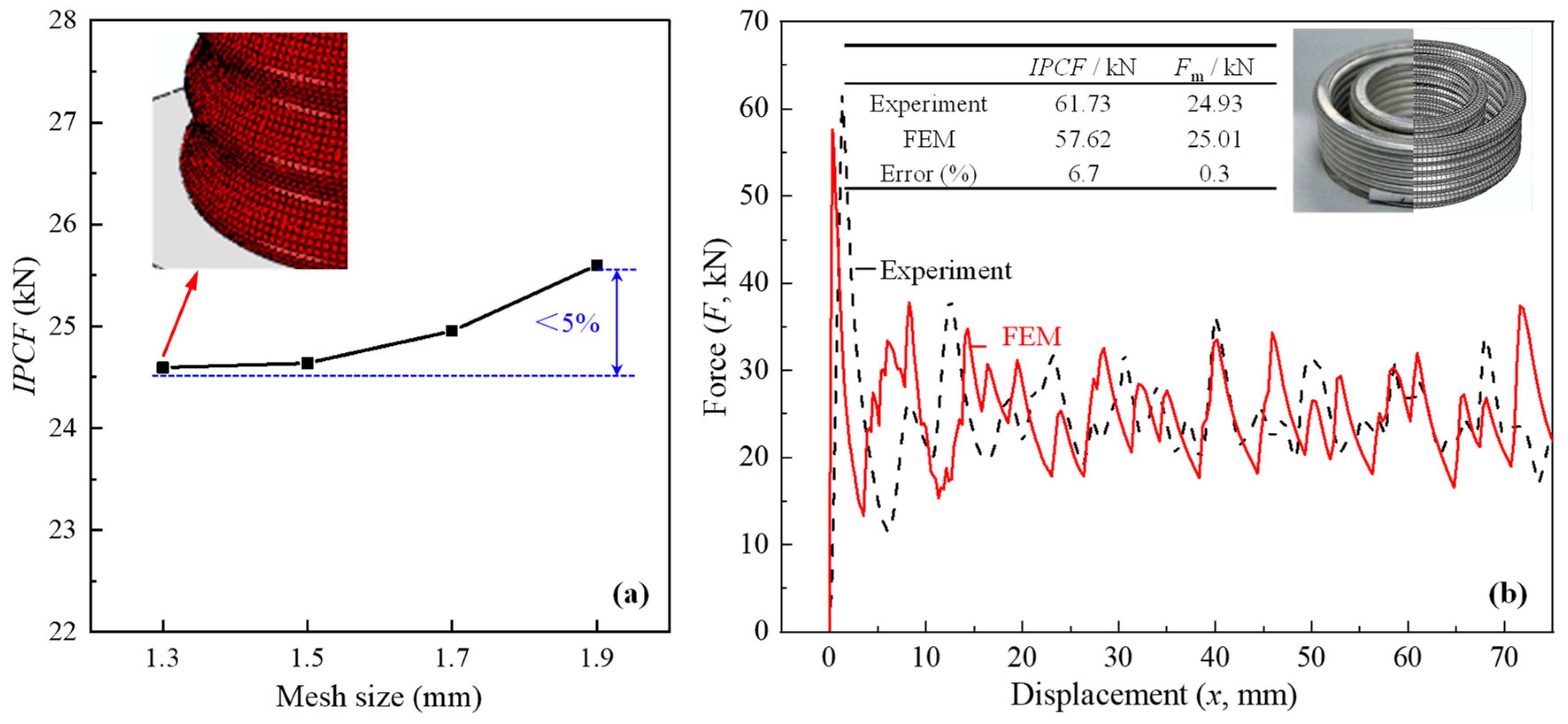
2.3. Finite Element Method (FEM) and Validation
3. Results and Discussion
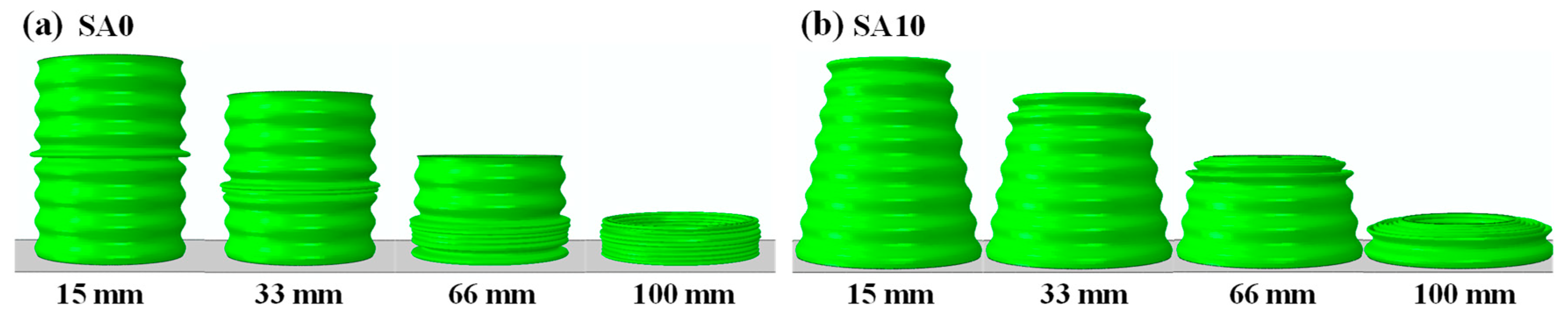
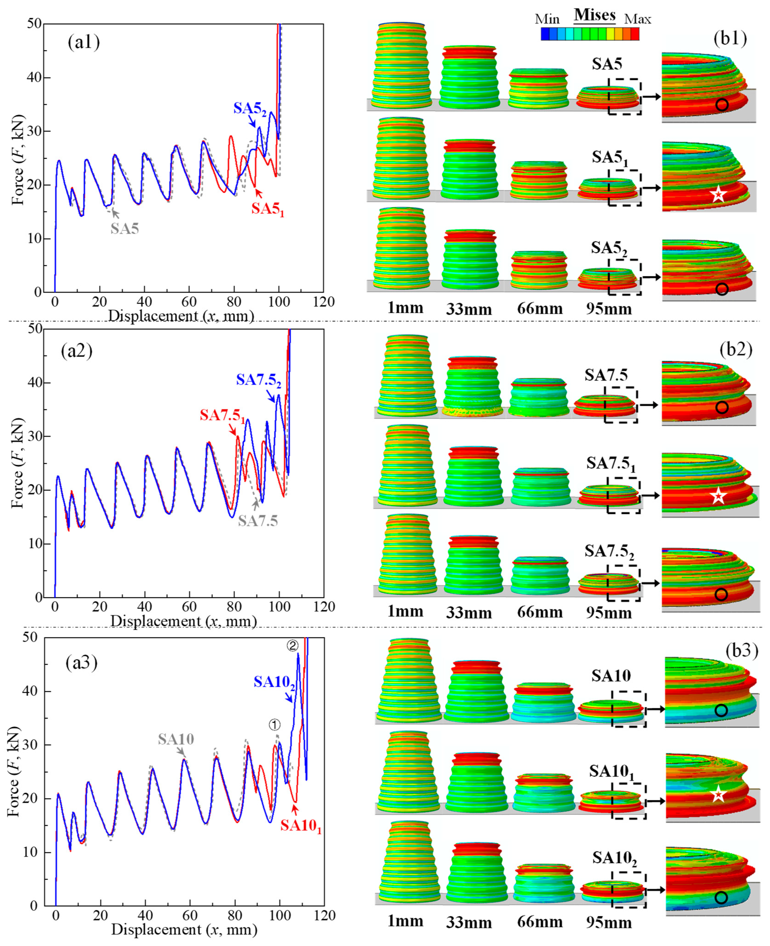
3.1. Deformation and Crashworthiness of CCTs with Different θ Values
3.2. Crashworthiness Performance and Influence Mechanism of Modified CCTs
4. Conclusions
- (1)
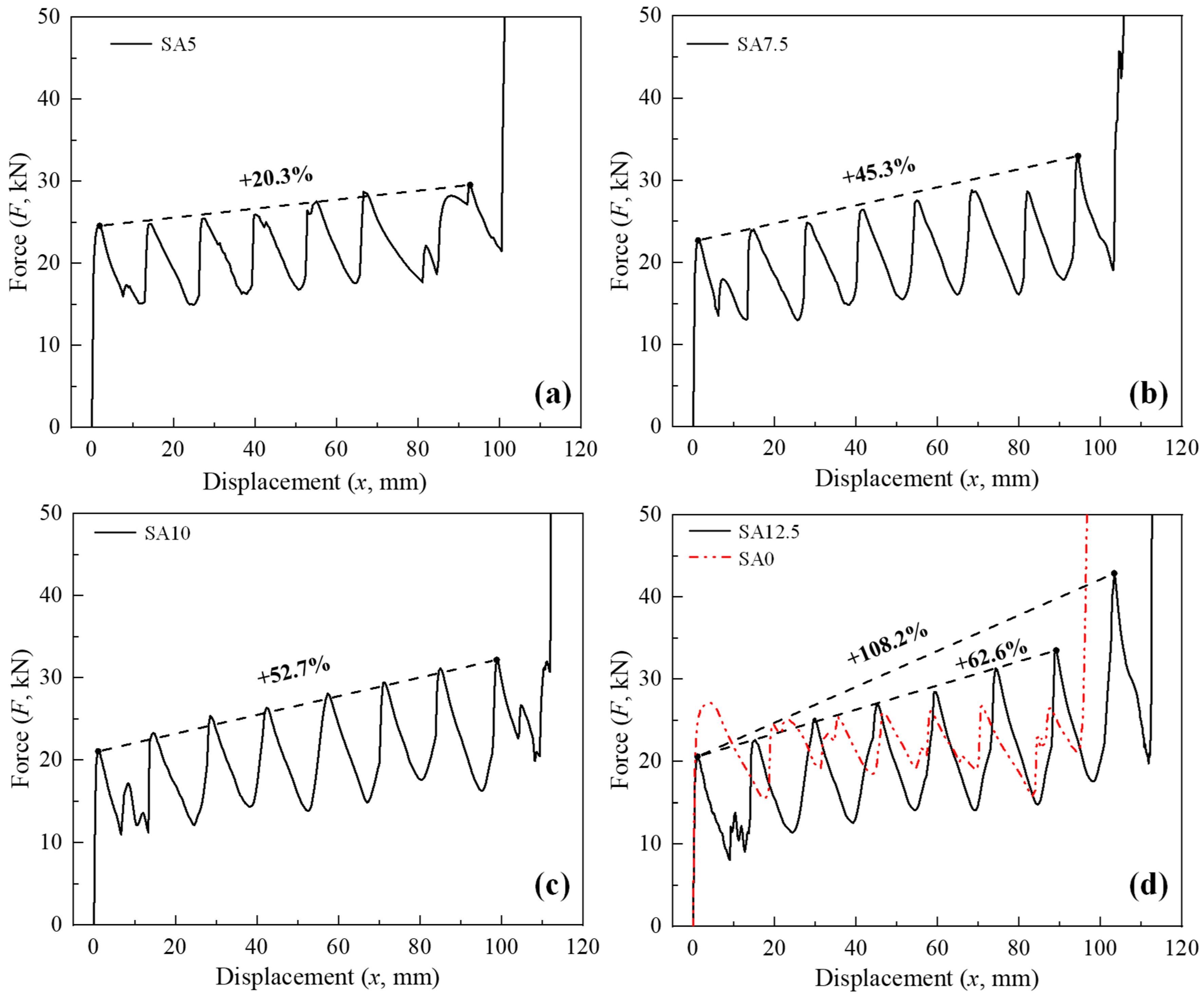
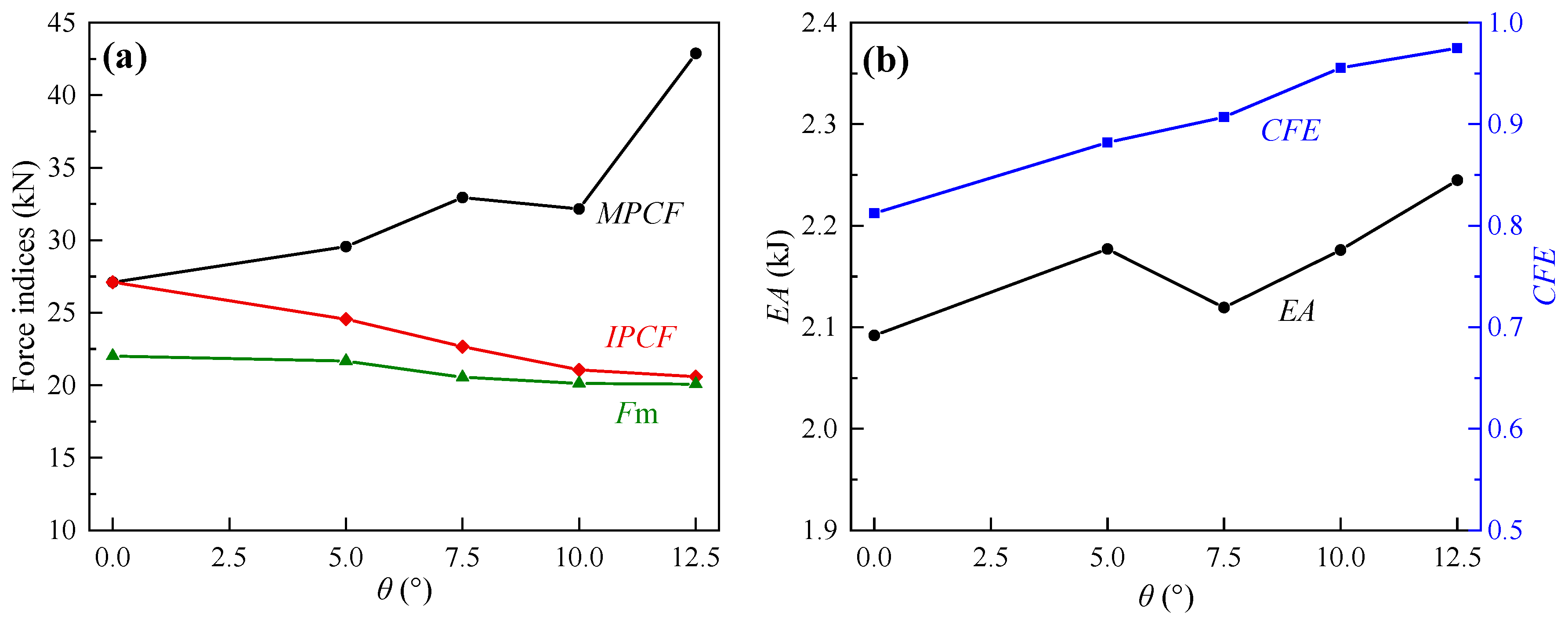
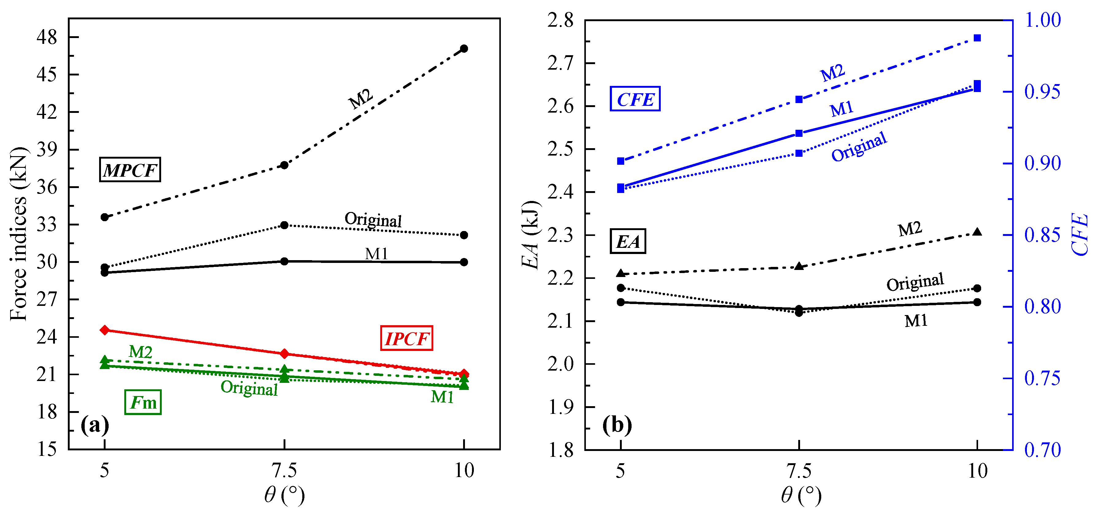
- By adding corrugations, the optimal semi-apical angle range of conical tubes was reduced from 10–15° to 5–10°. The Fm of the 5–10° CCTs was close to that of the corrugated straight tube (CST), but the IPCF was significantly smaller with larger CFE and EA. Taking SA5 as an example, compared to the corrugated straight tube its IPCF decreased by 9.38%, while CFE and EA increased by 4.08% and 8.58%, respectively. However, CCTs with different θ values all exhibited a gradual increase in the peak crushing force and a much higher MPCF than that of the CST;
- (2)
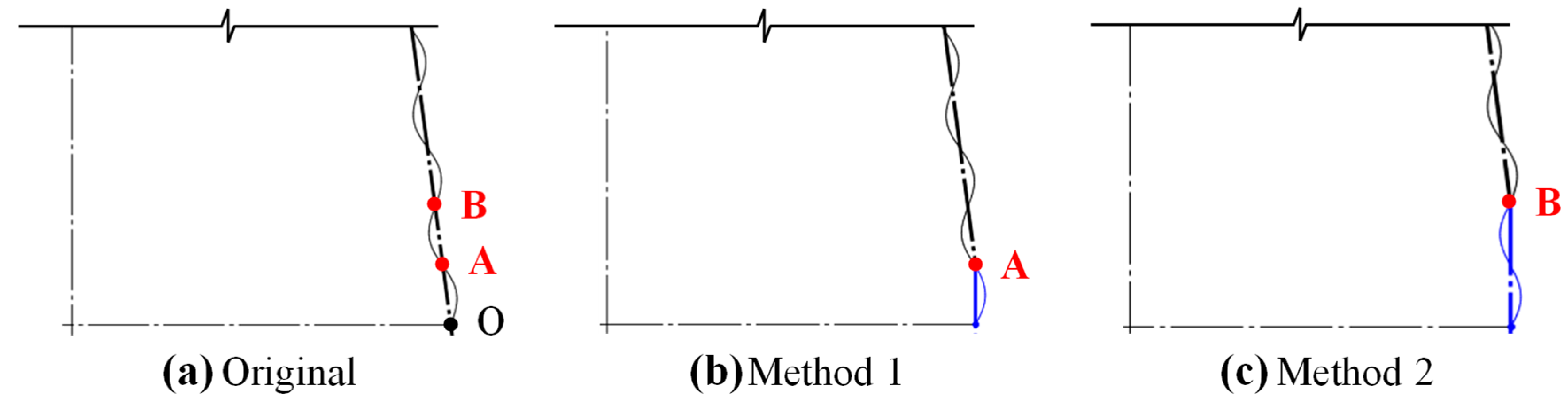
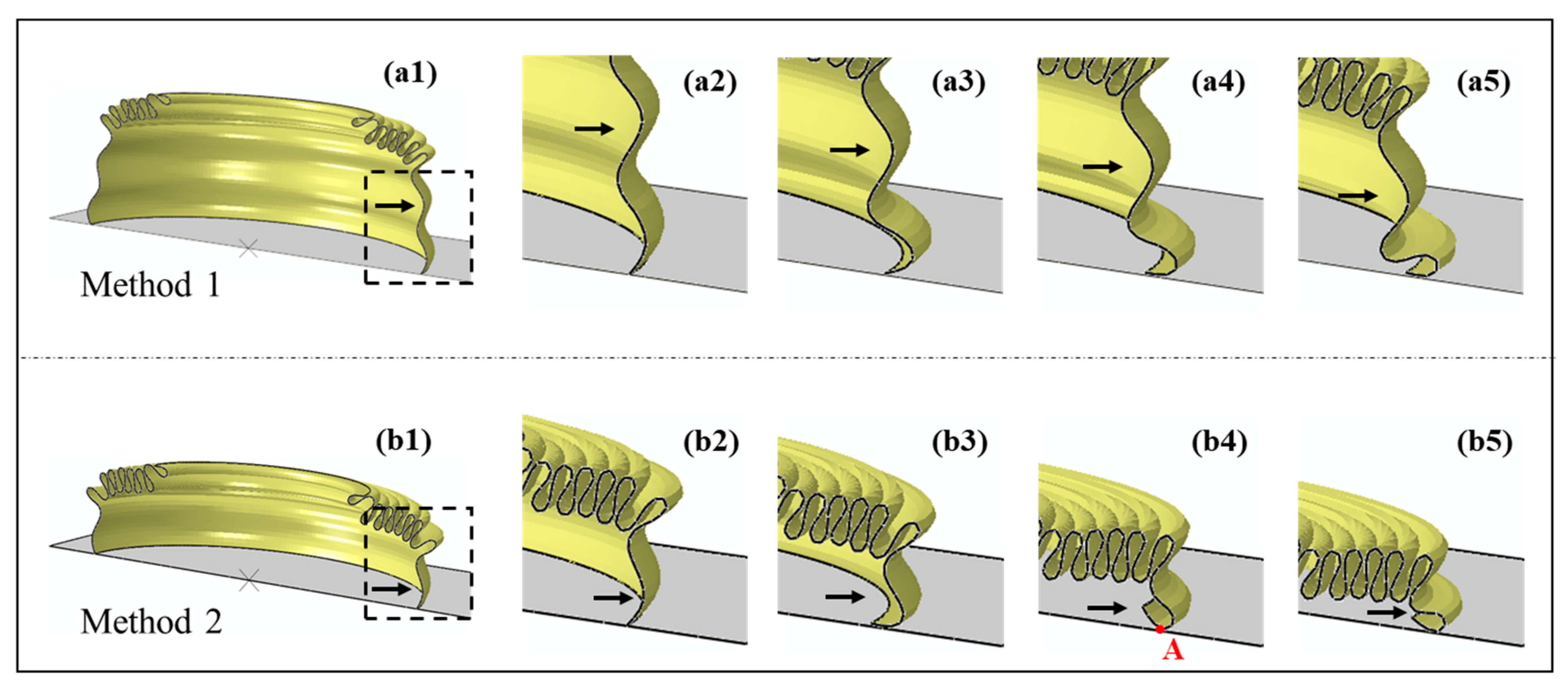
- Considering that the increasing diameter of CCTs from top to bottom is the major reason for the gradual growth of the peak crushing force, modification methods of “replacing the last one or two inclined half-wavelength corrugations with vertical corrugations at the bottom of CCTs” were proposed. Modification Method 1 effectively solved the problem of the large end peak crushing force of CCTs with a θ ≥ 7.5°. The reason for the different modification effects of the two modification methods was revealed to be the deformation of the last corrugation (eighth corrugation);
- (3)
- The applicable scenarios of modification were given: the 5° CCT does not need modification; 7.5° and 10° CCTs can consider adopting Method 1 to reduce the MPCF with Fm, EA, CFE and other crashworthiness indices basically unchanged;
- (4)
- This study comprehensively and systematically verified the crashworthiness characteristics of CCTs with a relatively small semi-apical angle, as well as the internal influence mechanism of the semi-apical angle on CCTs, which not only lays the foundation for the development of a new type of biomimetic single-cell and multi-cell crush box (tube) but also provides a numerical analysis basis and direct guidance for the application of the corrugated conical tube itself.
Author Contributions
Funding
Institutional Review Board Statement
Data Availability Statement
Acknowledgments
Conflicts of Interest
References
- Song, Y.; Hao, N.; Ruan, S.; He, C.; Ma, Q. Free vibration properties of beetle elytron plate: Composite material, stacked structure and boundary conditions. Mech. Mater. 2023, 185, 104754. [Google Scholar] [CrossRef]
- Song, Y.; Ruan, S.; Hao, N.; Okabe, Y. A novel cylindrical sandwich plate inspired by beetle elytra and its compressive properties. Sci. China Technol. Sci. 2024, 67, 3465–3476. [Google Scholar] [CrossRef]
- Baroutaji, A.; Sajjia, M.; Olabi, A.-G. On the crashworthiness performance of thin-walled energy absorbers: Recent advances and future developments. Thin Wall Struct. 2017, 118, 137–163. [Google Scholar] [CrossRef]
- Zhao, M. Research on Energy Absorption Characteristics of CFRP Aluminum Alloy Hybrid Tubes. Master’s Dissertation, Wuhan University of Technology, Wuhan, China, 2019. (In Chinese). [Google Scholar]
- Ha, N.S.; Lu, G.X. Thin-walled corrugated structures: A review of crashworthiness designs and energy absorption characteristics. Thin Wall Struct. 2020, 157, 106995. [Google Scholar] [CrossRef]
- Alkhatib, S.E.; Matar, M.S.; Tarlochan, F.; Laban, O.; Mohamed, A.S.; Alqwasmi, N. Deformation modes and crashworthiness energy absorption of sinusoidally corrugated tubes manufactured by direct metal laser sintering. Eng. Struct. 2019, 201, 109838. [Google Scholar] [CrossRef]
- Abdewi, E.F.; Sulaiman, S.; Hamouda, A.M.S.; Mahdi, E. Effect of geometry on the crushing behaviour of laminated corrugated composite tubes. J. Mater. Process. Tech. 2006, 172, 394–399. [Google Scholar] [CrossRef]
- Yao, R.Y.; Yin, G.S.; Hao, W.Q.; Zhao, Z.Y.; Li, X.; Qin, X.L. Axial buckling modes and crashworthiness of circular tube with external linear gradient grooves. Thin Wall Struct. 2019, 134, 395–406. [Google Scholar] [CrossRef]
- Mamalis, A.G.; Manolakos, D.E.; Spentzas, K.N.; Ioannidis, M.B.; Koutroubakis, S.; Kostazos, P.K. The effect of the implementation of circular holes as crush initiators to the crushing characteristics of mild steel square tubes: Experimental and numerical simulation. Int. J. Crashworthiness 2009, 14, 489–501. [Google Scholar] [CrossRef]
- Li, Z.X.; Ma, W.; Yao, S.G.; Xu, P. Crashworthiness performance of corrugation-reinforced multicell tubular structures. Int. J. Mech. Sci. 2021, 190, 106038. [Google Scholar] [CrossRef]
- Kilicaslan, C. Numerical crushing analysis of aluminum foam-filled corrugated single- and double-circular tubes subjected to axial impact loading. Thin Wall Struct. 2015, 96, 82–94. [Google Scholar] [CrossRef]
- Bai, Z.; Zhou, C.; Gong, C.; Zhang, L.; Tan, W.; Bu, X. Crashworthiness of bio-inspired hierarchical thin-walled square tubes. China J. Highw. Transp. 2020, 33, 181–190. [Google Scholar]
- Rawat, S.; Narayanan, A.; Upadhyay, A.K.; Shukla, K.K. Multiobjective optimization of functionally corrugated tubes for improved crashworthiness under axial impact. Procedia Eng. 2017, 173, 1382–1389. [Google Scholar] [CrossRef]
- Sadighi, A.; Mahbod, M.; Asgari, M. Bi-tubular corrugated composite conical-cylindrical tube for energy absorption in axial and oblique loading: Analysis and optimization. J. Compos. Mater. 2020, 54, 2399–2432. [Google Scholar] [CrossRef]
- Demirci, E.; Yıldız, A.R. An experimental and numerical investigation of the effects of geometry and spot welds on the crashworthiness of vehicle thin-walled structures. Mater. Test. 2018, 60, 553–561. [Google Scholar] [CrossRef]
- Demirci, E.; Yıldız, A.R. An investigation of the crash performance of magnesium, aluminum and advanced high strength steels and different cross-sections for vehicle thin-walled energy absorbers. Mater. Test. 2018, 60, 661–668. [Google Scholar] [CrossRef]
- Aye, C.M.; Pholdee, N.; Yildiz, A.R.; Bureerat, S.; Sait, S.M. Multi-surrogate-assisted metaheuristics for crashworthiness optimisation. Int. J. Vehicle Des. 2019, 80, 223–240. [Google Scholar] [CrossRef]
- Yıldız, B.S. Slime mould algorithm and kriging surrogate model-based approach for enhanced crashworthiness of electric vehicles. Int. J. Vehicle Des. 2020, 83, 54–68. [Google Scholar] [CrossRef]
- Yu, X.; Pan, L.; Chen, J.; Zhang, X.; Wei, P. Experimental and numerical study on the energy absorption abilities of trabecular–honeycomb biomimetic structures inspired by beetle elytra. J. Mater. Sci. 2018, 54, 2193–2204. [Google Scholar] [CrossRef]
- Yu, X.; Zhang, X.; Chen, J.; Pan, L.; Xu, Y.; Fu, Y. Experimental verification and optimization research on the energy absorption abilities of beetle elytron plate crash boxes. Mater. Res. Express. 2019, 6, 1165e2. [Google Scholar] [CrossRef]
- Zhao, T.; Lin, Q.; Chen, J. Buffering energy-absorbing performance of multi-cell octagonal biomimetic structure with cylinder and sinusoidal guide line. Proc. Inst. Mech. Eng. D-J. Automob. Eng. 2023, 09544070231210034. [Google Scholar] [CrossRef]
- Yang, M.; Han, B.; Su, P.B.; Wei, Z.H.; Zhang, Q.; Zhang, Q.C.; Lu, T.J. Axial crushing of ultralight all-metallic truncated conical sandwich shells with corrugated cores. Thin Wall Struct. 2019, 140, 318–330. [Google Scholar] [CrossRef]
- Yang, M.; Han, B.; Su, P.B.; Li, F.H.; Zhao, Z.N.; Zhang, Q.; Zhang, Q.C.; Hong, Z.J.; Lu, T.J. Oblique crushing of truncated conical sandwich shell with corrugated core. Mech. Adv. Mater. Struc. 2020, 28, 2458–2471. [Google Scholar] [CrossRef]
- Zhang, H.; Zhang, X. Crashworthiness performance of conical tubes with nonlinear thickness distribution. Thin Wall Struct. 2016, 99, 35–44. [Google Scholar] [CrossRef]
- Attar, A.A.; Kazemi, M. Investigation on crushing behavior of laminated conical absorbers with different arrangements under axial loading. Proc. Inst. Mech. Eng. Part L J. Mater. Des. Appl. 2020, 234, 394–407. [Google Scholar] [CrossRef]
- Guler, M.A.; Cerit, M.E.; Bayram, B.; Gerceker, B.; Karakaya, E. The effect of geometrical parameters on the energy absorption characteristics of thin-walled structures under axial impact loading. Int. J. Crashworthiness 2010, 15, 377–390. [Google Scholar] [CrossRef]
- Zou, M.; Wei, C.; Xu, S.; Zhao, Z.; Zhang, J. Energy absorption characteristics simulation of cone thin-walled metal tube research in the automotive collision. J. Automot. Saf. Energy 2012, 3, 326–331. (In Chinese) [Google Scholar]
- Moghaddam, A.M.; Kheradpisheh, A.; Asgari, M. A basic design for automotive crash boxes using an efficient corrugated conical tube. Proc. Inst. Mech. Eng. Part D J. Automob. Eng. 2021, 235, 1835–1848. [Google Scholar] [CrossRef]
- Nia, A.A.; Hamedani, J.H. Comparative analysis of energy absorption and deformations of thin walled tubes with various section geometries. Thin Wall Struct. 2010, 48, 946–954. [Google Scholar] [CrossRef]
- Azimi, M.B.; Asgari, M. Energy absorption characteristics and a meta-model of miniature frusta under axial impact. Int. J. Crashworthiness 2016, 21, 222–230. [Google Scholar] [CrossRef]
- Rezadoust, A.M.; Esfandeh, M.; Sabet, S.A. Crush behavior of conical composite shells: Effect of cone angle and diameter/wall thickness ratio. Polym. Technol. Eng. 2008, 47, 147–151. [Google Scholar] [CrossRef]
- Ahmadi, A.; Asgari, M. Efficient crushable corrugated conical tubes for energy absorption considering axial and oblique loading. Proc. Inst. Mech. Eng. Part C J. Mech. Eng. Sci. 2019, 233, 3917–3935. [Google Scholar] [CrossRef]
- Alkhatib, S.E.; Tarlochan, F.; Eyvazian, A. Collapse behavior of thin-walled corrugated tapered tubes. Eng. Struct. 2017, 150, 674–692. [Google Scholar] [CrossRef]
- Huang, C.; Deng, X. Crashworthiness analysis of double-corrugated multicellular tubes under axial impact. J. Braz. Soc. Mech. Sci. Eng. 2024, 46, 56. [Google Scholar] [CrossRef]
- Deng, X.; Lu, Q.; Liu, F.; Li, G. Energy absorption comparison of conventional and dual gradient hierarchical multicellular tubes under axial impact. J. Braz. Soc. Mech. Sci. Eng. 2023, 45, 182. [Google Scholar] [CrossRef]
- Fu, J.; Liu, Q.; Liufu, K.; Deng, Y.; Fang, J.; Li, Q. Design of bionic-bamboo thin-walled structures for energy absorption. Thin Wall Struct. 2019, 135, 400–413. [Google Scholar] [CrossRef]
- ASTM; E8/E8M-22 Standard Test Methods for Tension Testing of Metallic Materials. ASTM International: West Conshohocken, PA, USA, 2004.
- Wei, T.; Zhou, X.; Guo, J.; Zeng, S.; Ye, J.; Yang, X. Numerical analysis and theoretical study on axial compression performance of A6061 thin-walled conical tubes. China Mech. Eng. 2022, 33, 1725–1733, 1750. [Google Scholar]
- Singer, J.; Arbocz, J.; Weller, T. Buckling Experiments: Experimental Methods in Buckling of Thin-Walled Structures: Shells, Built-Up Structures, Composites and Additional Topics–Volume 2; John Wiley & Sons: New York, NY, USA, 2002. [Google Scholar]
- Jafarian, N.; Rezvani, M.J. Crushing behavior of multi-component conical tubes as energy absorber: A comparative analysis between end-capped and non-capped conical tubes. Eng. Struct. 2019, 178, 128–135. [Google Scholar] [CrossRef]
- Zhang, L.F.; Yu, W.Z.; Lan, X.; Wu, K.C.; Sun, B.F.; Wang, B.; Wan, Y.H.; Chen, D.G. Limiting device for isolation layer. Chinese Patent CN202222833121.7, 26 October 2022. (In Chinese). [Google Scholar]


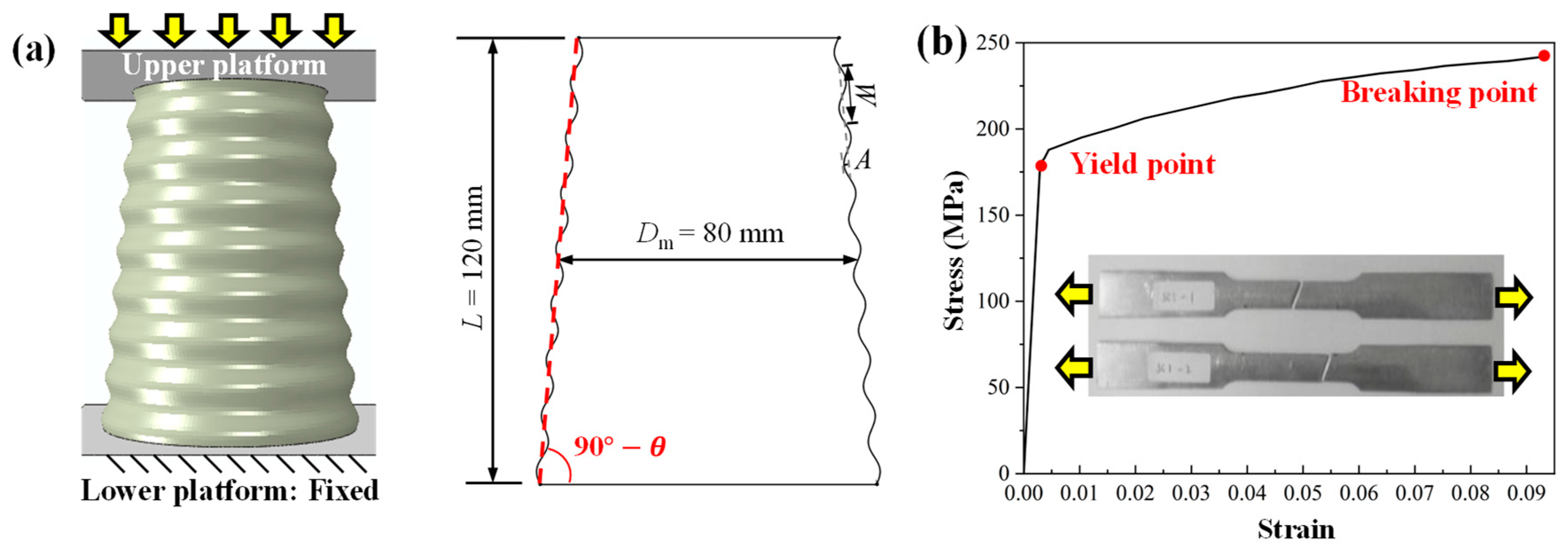
| Density | Young’s Modulus | Poisson’s Ratio | Yield Strength | Tensile Strength | Elongation |
|---|---|---|---|---|---|
| 2700 kg/m3 | 68.5 GPa | 0.33 | 179.67 MPa | 241.83 MPa | 9.98% |
Disclaimer/Publisher’s Note: The statements, opinions and data contained in all publications are solely those of the individual author(s) and contributor(s) and not of MDPI and/or the editor(s). MDPI and/or the editor(s) disclaim responsibility for any injury to people or property resulting from any ideas, methods, instructions or products referred to in the content. |
© 2025 by the authors. Licensee MDPI, Basel, Switzerland. This article is an open access article distributed under the terms and conditions of the Creative Commons Attribution (CC BY) license (https://creativecommons.org/licenses/by/4.0/).
Share and Cite
Song, Y.; Lin, Q.; Chen, J.; Zhao, T. A Numerical Study on the Crashworthiness of Corrugated Conical Tubes with Small Semi-Apical Angles and Their Influence Mechanism. Biomimetics 2025, 10, 29. https://doi.org/10.3390/biomimetics10010029
Song Y, Lin Q, Chen J, Zhao T. A Numerical Study on the Crashworthiness of Corrugated Conical Tubes with Small Semi-Apical Angles and Their Influence Mechanism. Biomimetics. 2025; 10(1):29. https://doi.org/10.3390/biomimetics10010029
Chicago/Turabian StyleSong, Yiheng, Qinyu Lin, Jinxiang Chen, and Tidong Zhao. 2025. "A Numerical Study on the Crashworthiness of Corrugated Conical Tubes with Small Semi-Apical Angles and Their Influence Mechanism" Biomimetics 10, no. 1: 29. https://doi.org/10.3390/biomimetics10010029
APA StyleSong, Y., Lin, Q., Chen, J., & Zhao, T. (2025). A Numerical Study on the Crashworthiness of Corrugated Conical Tubes with Small Semi-Apical Angles and Their Influence Mechanism. Biomimetics, 10(1), 29. https://doi.org/10.3390/biomimetics10010029