Article

Investigation of the Influence of Silicon Oxide Content on Electrolyte Degradation, Gas Evolution, and Thickness Change in Silicon Oxide/Graphite Composite Anodes for Li-Ion Cells Using Operando Techniques

1
Department of Applied Electrochemistry, Fraunhofer Institute for Chemical Technology ICT, Joseph-von-Fraunhofer-Str. 7, 76327 Pfinztal, Germany
2
Institute for Mechanical Process Engineering and Mechanics, Karlsruhe Institute of Technology KIT, Straße am Forum 8, 76131 Karlsruhe, Germany
*
Author to whom correspondence should be addressed.
These authors contributed equally to this work.
Batteries 2023, 9(9), 449; https://doi.org/10.3390/batteries9090449
Submission received: 7 August 2023 / Revised: 25 August 2023 / Accepted: 28 August 2023 / Published: 1 September 2023
(This article belongs to the Section Battery Modelling, Simulation, Management and Application)

Abstract

:
This research paper investigates the influence of varying silicon oxide (SiO x ) content on the performance and aging of lithium-ion cells. In-depth investigations encompass charge and discharge curves, thickness changes, electrolyte degradation, gas evolution, and chemical analysis of cells with different silicon oxide proportions in the anode and their associated cathodes. The results show that a higher silicon oxide content in the anode increases the voltage hysteresis between charge and discharge. Moreover, the first-cycle efficiencies decrease with a higher silicon oxide content, attributed to irreversible Li x Si y formation and the subsequent loss of active lithium from the cathode during formation. The anodes experience higher thickness changes with increased silicon oxide content, and peaks in differential voltage curves can be correlated with specific anode active materials and their thickness change. A gas analysis reveals conductive salt and electrolyte intermediates as well as silicon-containing gaseous fragments, indicating continuous electrolyte decomposition and silicon oxide aging, respectively. Additionally, a chemical analysis confirms increased silicon-derived products and electrolyte degradation on electrode surfaces. These findings underscore the importance of a holistic aging investigation and help understand the complex chemical changes in electrode materials for designing efficient and durable lithium-ion cells.

1. Introduction

In recent years, the ever-increasing demand for high-performance energy storage systems has fueled intensive research in the field of lithium-ion batteries (LIB). They have become the preferred choice for numerous applications, ranging from portable electronics to electric vehicles and grid-scale energy storage. To meet the growing demand for longer-lasting, safer, and more efficient Li-ion batteries, researchers are continually exploring innovative approaches to enhance their performance [1]. Traditional graphite anodes have been widely used due to their stability and good cycling performance. However, the limited theoretical capacity of graphite has led researchers to investigate alternative materials with higher energy densities. Silicon (Si) has emerged as a promising candidate due to its exceptional theoretical capacity, nearly ten times higher than that of graphite [2]. Nevertheless, Si anodes suffer from substantial volume expansion during lithiation (≈300% compared to ≈10% for graphite [3]), leading to mechanical stress, rapid capacity fading, and poor cycling stability [4,5].
In the search for improved lithium-ion battery anodes, attention has turned to alternative silicon-based options like SiO x , nanospheres, nanotubes, Si-nanolayer-embedded graphite/carbon hybrids, etc. to boost energy storage and performance [2]. Pure silicon’s expansion limitations during cycles have led to interest in silicon oxide as an alternative. SiO x offers stability, controlled swelling, quicker kinetics, inherent safety, and cost-effectiveness, making it a promising solution [6].
Nonetheless, there are still challenges. To address the challenges associated with Si-containing anodes, one approach that has gained significant attention is the development of graphite–silicon composite anodes. These composite structures harness the advantageous properties of both materials, combining the high capacity of silicon (oxide) with the mechanical stability of graphite. This hybridisation has shown promising results in mitigating volume expansion issues and improving the overall battery performance [7].
However, several critical aspects related to the implementation of Si-containing anodes remain to be thoroughly investigated. This research paper aims to shed light on various essential topics associated with Li-ion batteries utilising silicon-containing anodes. The key areas of focus include aging phenomena such as thickness change and gas analysis investigated in operando and also with post mortem analysis. The aging investigations will delve into the degradation mechanisms that occur within Si-containing anodes with varying silicon content, investigated during formation cycling, examining the impact of capacity loss, rate capability, impedance growth, and morphological changes [8,9]. Additionally, the paper will discuss the challenges posed by thickness change in silicon-containing anodes, addressing issues such as mechanical stress, electrolyte degradation, and gas evolution. Furthermore, gas analysis techniques will be explored to understand the evolution of gases (e.g., electrolyte decomposition products) during battery operation [10,11,12]. Mass spectrometry will be utilised to identify and quantify these gases, providing valuable insights into the degradation mechanisms and safety concerns associated with Si-containing anodes [4,10,13].
Operando measurements, which involve studying battery performance under realistic operating conditions, will provide a comprehensive understanding of the electrochemical processes occurring within Si(-oxide)-containing anodes. This real-time monitoring allows for the direct observation of structural and compositional changes, enabling researchers to gain insights into the performance limitations [14]. Lastly, post mortem analysis will play a crucial role in characterising the cells after formation and the possible failure modes with increasing silicon oxide content and identifying the underlying causes of battery degradation. By comprehensively investigating these essential aspects, this research paper aims to contribute to the understanding of Si-containing anodes in Li-ion batteries, paving the way for the development of high-performance energy storage systems with improved stability, safety, and longevity.

2. Materials and Methods

2.1. Electrode Preparation

The anodes used in this work were produced in-house. The starting materials graphite (Gr, MAG-HE3, Hitachi Chemical Co., Ltd., Tokyo, Japan), silicon composite oxide (SiO x , DMSO80, Daejoo Electronic Materials Co., Ltd., Siheung, Republic of Korea), and carbon black (CB, Super C65, Imerys Graphite & Carbon Switzerland SA, Bodio, Switzerland) and binders carboxymethyl cellulose (CMC, Walocel CRT W2000, DuPont de Nemours, Inc., Wilmington, DE, USA) and styrene butadiene rubber (SBR, ZEON CORPORATION, Tokyo, Japan) were processed into a slurry in a laboratory-scale speed mixer (Thinky ARE 250, Thinky Corporation, Tokyo, Japan) and coated on 12 µm Cu-foil (Litarion GmbH, Kamenz, Germany) with an automated film applicator (Coatmaster 510, Erichsen GmbH & Co. KG, Hemer, Germany) and a doctor blade (ZUA 2000.100, Zehntner GmbH, Reigoldswil, Switzerland). The single-sided electrode density was set to 1.35 g cm 3 ± 5% and the single-sided area capacity was adjusted to 3.50 mAh cm 2 ± 3%. Porosity was set to 38% ± 5% using a calander (SUMET CA9/250-200, Sumet Systems GmbH, Denklingen, Germany). The exact electrode composition is given in Table 1. The cathodes used were commercially available coatings from SK INNOVATION CO., LTD. (Seoul, Republic of Korea) with nickel–manganese–cobalt–oxide (NMC622) as the active material, polyvinylidene fluoride (PVDF) as binder, and CB as conductive additive, coated on 12 µm Al-foil. The exact composition is also given in Table 1. The single-sided electrode density was 3.0 g cm 3 , the single-sided area capacity was 3.60 mAh cm 2 , and the porosity was 29%. Thicknesses (Table 1) were measured using a micrometer screw (QuantuMike, Mitutoyo America Corporation, Aurora, IL, USA).

2.2. Operando Electrochemical Measurements

All cells in this work were tested with a CTS Lab and CTS Lab XL cell tester from Basytec GmbH (Asselfingen, Germany). Dilatometer measurements and standard electrochemical measurements were conducted in a climate chamber from Weiss Umwelttechnik GmbH (Wien, Austria) at a constant 25 C. The cells for the differential electrochemical mass spectrometry (DEMS) measurements were tested in an Ar-filled glovebox (MBraun GmbH (Garching bei München, Germany), H 2 O < 0.1 ppm, O 2 < 0.1 ppm).

2.2.1. Test Cells and Evaluation of Recorded Data

The tests of half and full cells of small laboratory formats were carried out with ECC-Std. and ECC-REF. test cells from EL-Cell GmbH (Hamburg, Germany). Both cell types use electrodes with a diameter of 18 mm, which were punched out using a special tool (EL-Cut by EL-Cell GmbH). As electrolyte, 500 µL 1 M LiPF 6 in EC/DEC (50:50 v/v) (Sigma-Aldrich, St. Louis, MO, USA) with 5 wt.-% FEC (99%, Sigma-Aldrich) was used. In order to obtain more sample mass and a larger sample area, small, multi-layered pouch cells with a cathode size of 4.0 cm × 2.2 cm (anode: 4.1 cm × 2.3 cm) were also built and used for the investigations. The cells were built in an Ar-filled glovebox (GS Glovebox Systemtechnik GmbH (Malsch, Germany), H 2 O < 0.1 ppm, O 2 < 0.1 ppm). For the half-cell setup, lithium metal (18 mm × 0.3 mm, Sigma Aldrich) was used as counter electrode. In the case of the full cells, the resulting areal balancing between anode and cathode was a/c ≈ 1.1.
Formation cycling was carried out as follows: For the half-cell setup a voltage range of 1.50–0.005 V for the anode and 2.50–4.30 V for the cathode was used. The first cycle was performed with C/20 constant current (CC) charging and discharging (i.e., lithiation and delithiation in half-cell setup). The second and third cycles were performed with C/10 and C/5, respectively each with a constant current and constant voltage (CC-CV) and a C/20 cut-off current for lithiation. For delithiation, C/10 and C/5 CC only, respectively, were used as current. The full cells were formatted with the same formation protocol but in a voltage range of 2.50–4.20 V. Between each (half-)cycle there was a pause of 15 min.
Various electrochemical test methods were applied and the influence of the silicon oxide content was analysed with the data obtained. Since silicon and graphite are delithiated separately from each other in different voltage ranges, with the help of differential voltage (DV) and differential capacity (DC) analysis, specific statements can be made for each active material in the electrode [14,15]. Particularly for cells containing silicon, the precise steps for the DV aging analysis were described in detail by Zilberman et al. [16] and Sturm et al. [17].

2.2.2. Differential Electrochemical Mass Spectrometry

A single mass spectrometer unit (QMG220 by Pfeiffer Vacuum GmbH, Aßlar, Germany) with a mass range of 0–200 m/z and a gas-tight ion source was used for the operando DEMS measurements. The connection between the measuring cell and MS was realised through a heated fused silica capillary. The cells were cycled according to Section 2.2.1 for three cycles in the same voltage range with different currents. The gas flow rate within the capillary was approximately 15 µL min 1 . With the help of an HI Cube 80 Classic vacuum system (Pfeiffer Vacuum GmbH), the gas space above the electrode stack was extracted. Using multiple ion detection (MID), it is possible to constantly record up to 128 m/z values over time for the measurement data acquisition. According to a species’ concentration in the cell atmosphere, the signal intensity increased. Analogue scans were performed periodically and allowed a single run over the entire mass range. A comparable test setup was already used by Kreissl et al. [18].

2.2.3. Dilatometry

The thickness change of single anodes and cathodes was measured using a dilatometer of the type ECD-3 from EL-Cell GmbH. The sensor unit can obtain displacement signals of <50 nm and the working range of the instrument is 500 µm. The working electrode (10 mm in diameter) and the counter electrode (12 mm in diameter) are separated by a porous glass separator to guarantee that only the thickness change of the working electrode is recorded. All parts were dried overnight at 100 C in vacuum. The dilatometer cell was, like the other test cells, assembled in an Ar-filled glovebox described in Section 2.2.1. A concentration of 345 µL electrolyte was used and the cells were cycled as described in Section 2.2.1 but with C/40 without resting between charging and discharging to gain a high measurement resolution.

2.3. Post Mortem Analysis

2.3.1. Chemical and Component Analysis

Before disassembling the cells in an Ar-filled glovebox (GS Glovebox Systemtechnik GmbH, H 2 O < 0.1 ppm, O 2 < 1 ppm), the relevant cells were discharged with C/20 to 2 V in the case of full cells and delithiated to 1.5 V for the anode half cells. The electrolyte was extracted with methylene chloride (DCM, Sigma-Aldrich) and the electrodes were washed twice in dimethyl carbonate (DMC, Sigma-Aldrich).
For analysing the electrode components of the cycled and discharged electrodes and several decomposition products of the electrolyte, surface and cross-section scanning electron microscopy (SEM, Mira3 XMU by Tescan, a.s., Brno, Czech Republic) with energy dispersive X-ray spectroscopy (EDX, Quantax XFlash®5030, Bruker Corporation, Billerica, MA, USA) were used. To investigate the electrodes gravimetrically, thermogravimetric analysis (TGA, Q5000 by TA Instruments Inc., New Castle, DE, USA) was used. With inductively coupled plasma-optical emission spectrometry (ICP-OES, Spectroblue by SPECTRO Analytical Instruments GmbH, Kleve, Germany), the electrode composition was analysed. Photometric measurements to investigate the silicon content in the anodes were performed using a Gallery Plus (Thermo Fisher Scientific Inc., Waltham, MA, USA). With the help of HF, the silicon compounds contained in the sample are converted into water-soluble H 2 SiF 6 , which reacts with the help of H 3 BO 3 to the blue-coloured H 6 [H 2 SiMo 12 O 4 ], whose presence can be photometrically evaluated quantitatively at 810 or 880 nm [9].

2.3.2. Gas Chromatography with Coupled Mass Spectrometry (GC-MS)

An Agilent 7820A gas chromatograph with a flame ionisation detector (FID) (Agilent Technologies, Inc., Santa Clara, CA, USA) and an Agilent 5977B mass spectrometer (Agilent Technologies, Inc.) were used for post mortem analysis of the gas phase in the test cells. The samples were fed through a heated gas-injection valve (Teckso GmbH, Neukirchen-Vluyn, Germany) with a sample loop of 500 µL. For separation, a medium polarity, 60 m long column with an inner diameter of 0.32 mm and a film thickness of 1.8 µm was used. By using the NIST database and its corresponding mass spectra, possible substances were identified qualitatively [19]. A special setup made it possible to evacuate and argon-purging the injection line prior to sample introduction. By evacuating the sample line of the GC device and opening the shut-off valve on the test cell, the gas sample was transferred. Adding argon before injection onto the GC separation column made up for any residual negative pressure in the system. This setup was already used for gas analytical studies by Kreissl et al. [18]. Another GC (8610V, SRI Instruments Europe, Bad Honnef, Germany) was added for additional qualitative gas analysis. It was equipped with a dedicated combination of a mole sieve 13X, silica gel separation column, FID, and thermal conductivity detector (TCD). As stated in the preceding paragraph, the gas sample was added to this GC system.

3. Results and Discussion

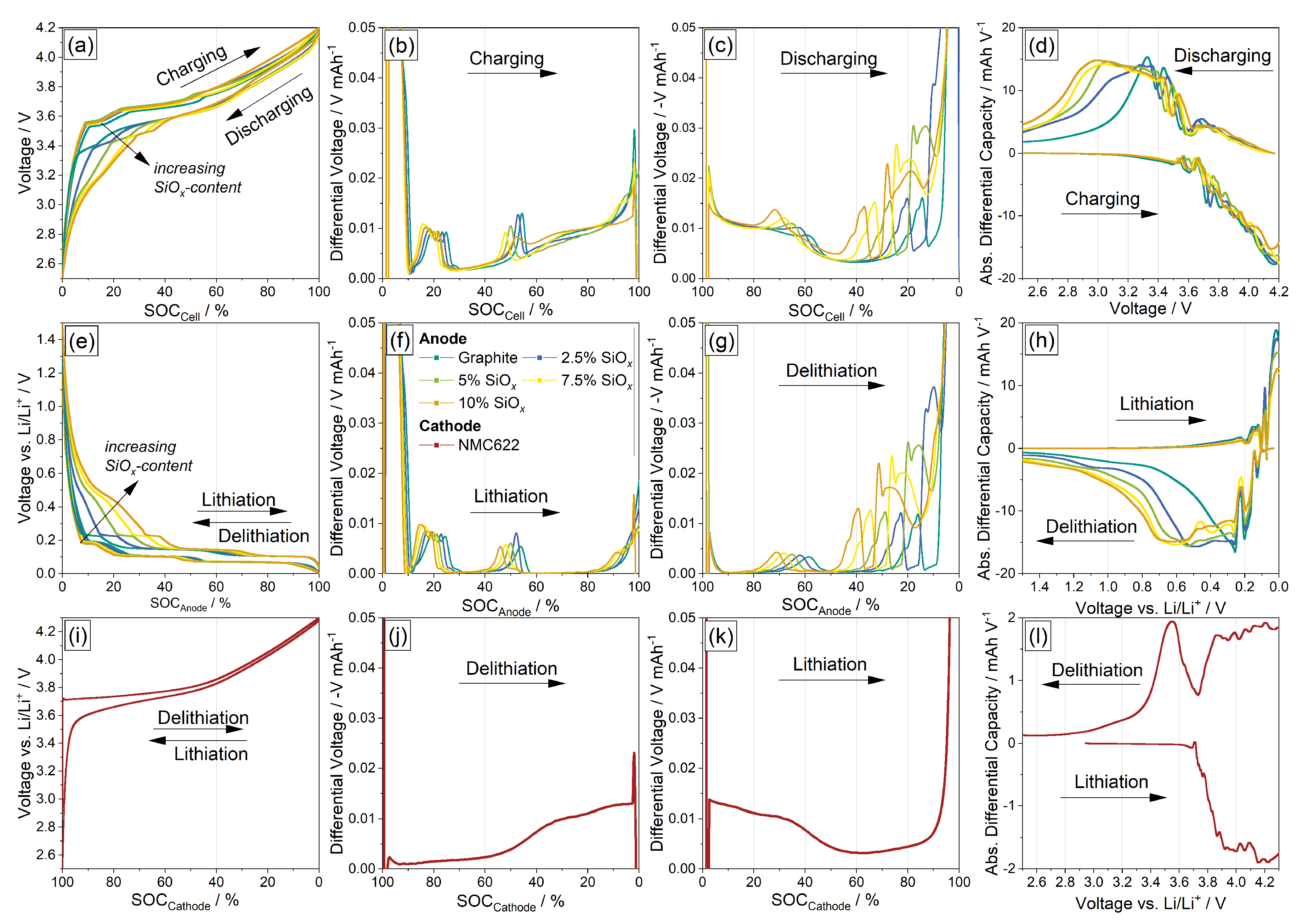
3.1. Electrochemical Measurements

With varying silicon content, the charge and discharge curves of the cells also change, which is shown in Figure 1. There, the results of the electrochemical measurements are presented. The first line (a–d) shows the full cell (i.e., anodes with varying silicon content versus the NMC622 cathode), the second line (e–h) shows the anode half-cell (anode vs. Li/Li + ) measurements, and the third line (i–l) shows the cathode half-cell (cathode vs. Li/Li + ) measurements. The first column shows voltage vs. SOC, the second column DV analysis for charging, the third column DV analysis for discharging, and the fourth column DC analysis. Charging and discharging, respectively, the lithiation and delithiation direction, is indicated. In Figure 1a,e the increasing voltage hysteresis between charge and discharge with increasing silicon content is indicated. When looking at Figure 1e it is visible that this hysteresis is caused by the silicon in the anode [20]. This is due to the different operating voltages of silicon (approximately 0.3 V) and graphite (approximately 0.1 V) versus lithium [21]. One reason is that lithium is intercalated into graphite’s lattice structure, whereas silicon forms an alloy with lithium [22]. Figure 1b,f show the parallel lithiation of graphite and silicon and Figure 1c,g show the separated delithiation of graphite and silicon in different voltage regions. This phenomenon was investigated in detail by Yao et al. [14] and Berhaut et al. [15].
The silicon capacity shares, i.e., how much capacity the silicon contributes to the total capacity of the anode, for the investigated electrode compositions are 15.6% (2.5 wt.-% SiO x ), 20.7% (5 wt.-% SiO x ), 27.2% (7.5 wt.-% SiO x ), and 32.6% (10 wt.-% SiO x ). Because of the different voltage windows in which the SiO x is used, the results differ a little bit between the half-cell setup (Figure 1g) and full-cell setup (Figure 1c). The cathode actually only leads to a shift in the curves in the y-direction and introduces no additional peaks (Figure 1j,k).
In Figure 2, the first-cycle efficiencies (FCE) for the investigated cells are presented. Figure 2a shows the results for the half-cell setup and Figure 2b shows the FCE for the full-cell setup. It is clearly visible that the FCE decreases with increasing silicon content. Obravac et al. and Zhang et al. showed that this is due to irreversible formation of Li x Si y [5,23]. The FCE even further decreases in the full-cell setup due to the loss of active lithium from the cathode during formation [4,21,24]. An overview is also given in Table 2. Figure 2b shows on the right y-axis the end voltage of discharge (delithiation of the anode) measured in the full-cell setup in laboratory test cells with a Li reference electrode after the first cycle of formation (I = C/20). The anodes’ end voltage of discharge increases with increasing silicon content. To reach the same end-of-discharge voltage (here, 2.5 V), the anode has to be delithiated to higher voltages, which in turn is disadvantageous for anode aging [9,25]. This can be also seen in Figure 3.

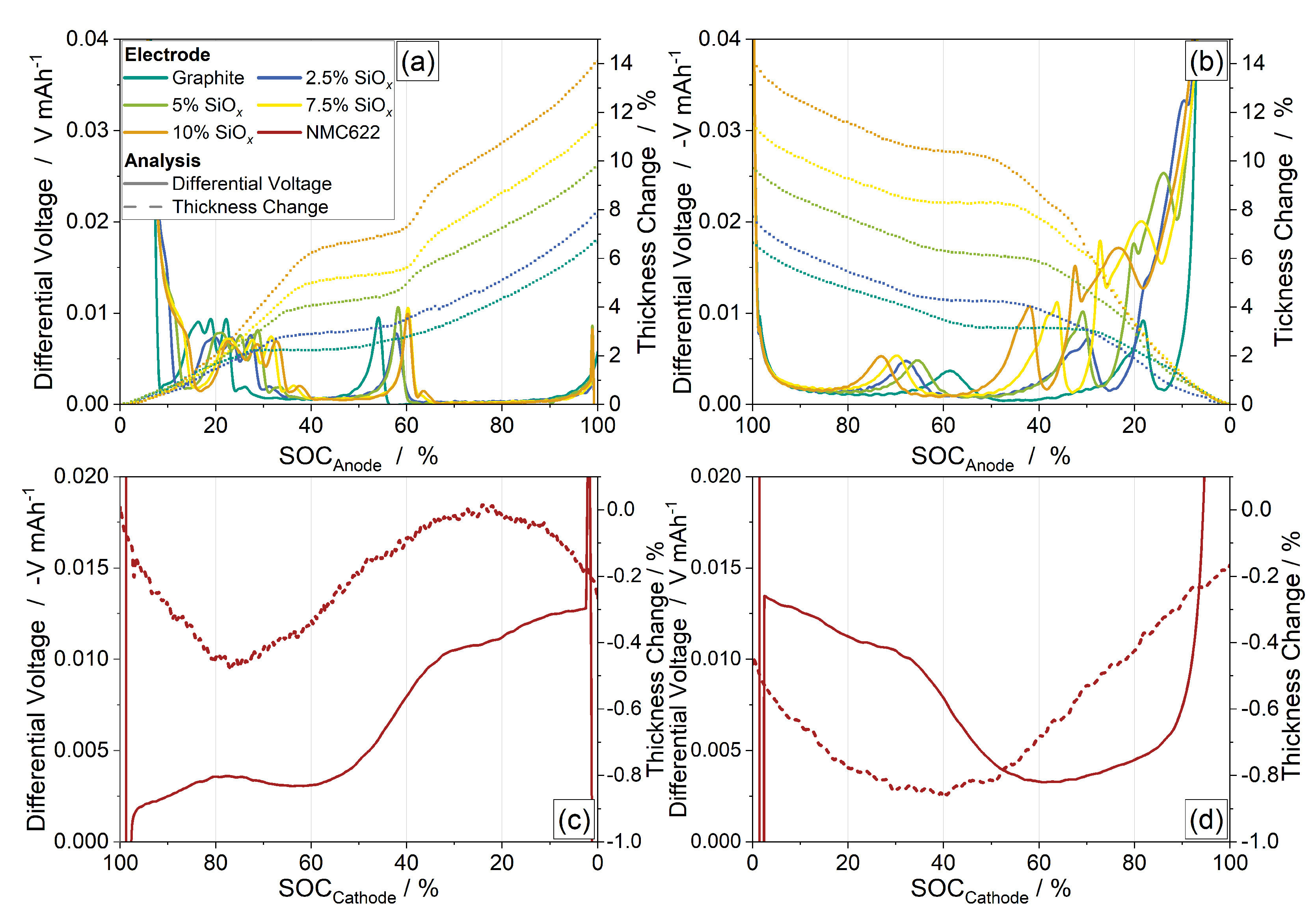
3.2. Thickness Change

Figure 3 shows the thickness and DV curves of the investigated anodes (Figure 3a,b) and cathode (Figure 3c,d). The anodes show a steady increase in thickness during lithiation and a steady decrease during delithiation for graphite anodes as well as Gr/SiO x composite anodes. With increasing silicon content (i.e., silicon capacity share), the overall thickness change increases. The peaks in the DV curves could be clearly assigned to the specific anode active materials. The gradient of the thickness curve changes with each peak. In Figure 1e a voltage plateau during lithiation can be seen at about 0.1 V, which is caused by the stage change 2 L → 2 of the graphite in the anode [26,27]. The same plateau occurs in delithiation (Figure 1e), which is caused by the stage change 2 → 2 L [27]. The plateau is at a slightly higher voltage (≈0.2 V) because in this voltage range during delithiation, the silicon is not yet electrochemically active [14].
The dilations of graphite and silicon are to be recognised separately during delithiation of the anode, as already explained for the silicon capacity share at the beginning of this section. These results also agree with the theoretically calculated thickness change curves of Gr/Si composite electrodes by Louli et al. [7]. Bazlen et al. and Heugel et al. showed that a reduced voltage window is connected to a smaller thickness change and therefore less silicon aging [9,25]. The thickness change is between 6.7% for the graphite cell (without silicon) and 14.1% for the anode with 10 wt.-% SiO x . In this case, the graphite thickness change is 6.5% and the thickness change of the SiO x is 7.6% (for a 32.6% silicon capacity share). For the anode with 5 wt.-% SiO x , the graphite thickness change is 6.4% and the thickness change of the SiO x is 3.3% (for a 20.1% silicon capacity share). The non-linear thickness change of the cathode, which is a result of the change in the lattice parameter c of the NMC crystal structure, has a difference of about 0.85% between lithiation and delithiaton, nearly negligible compared to the anode [28].

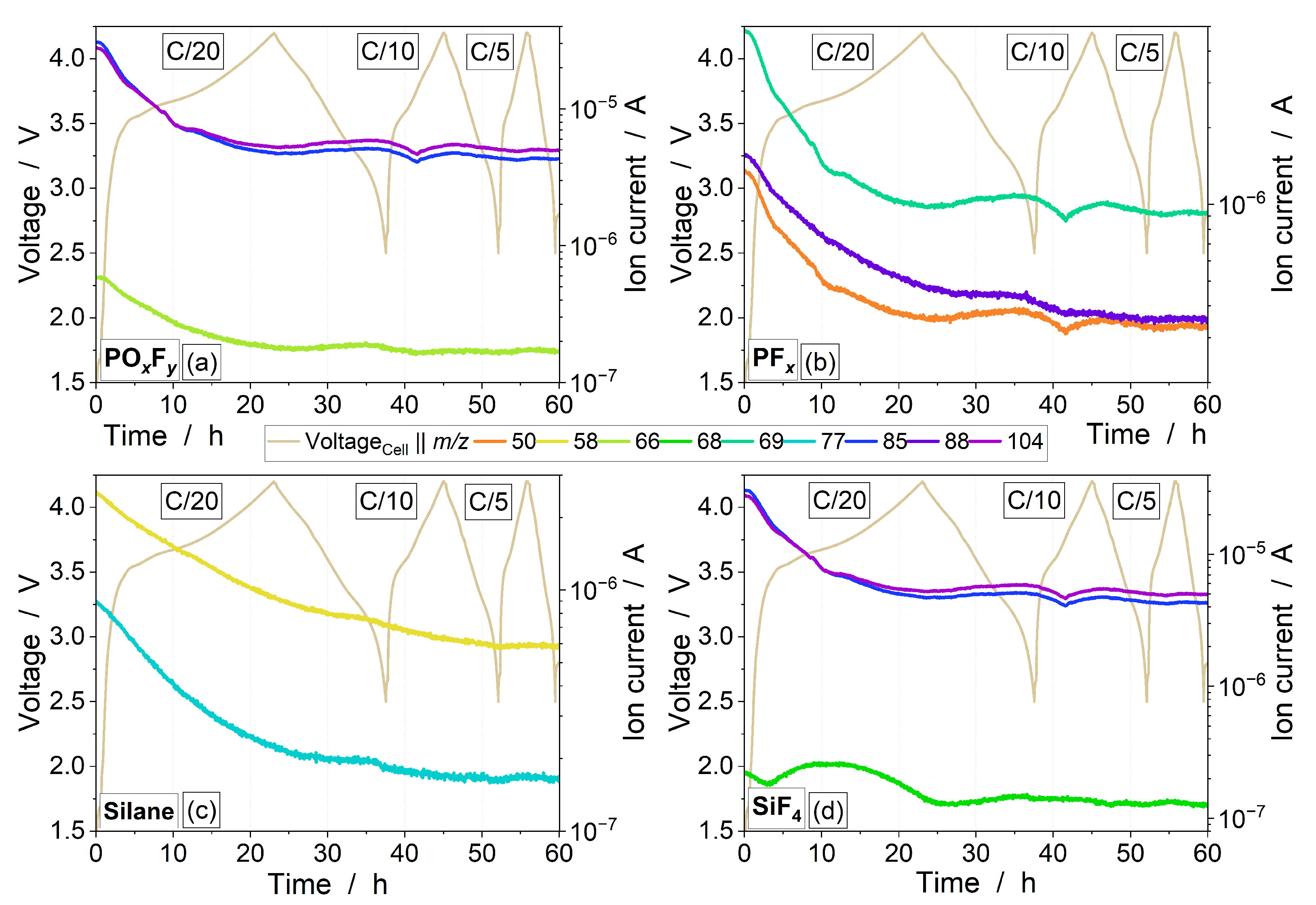
3.3. Electrolyte Degradation

Figure 4 shows a representative GC-MS chromatogram after cell formation for a full cell with 25 wt.-% SiO x -containing graphite anode and NMC622 cathode according to Table 1. The total ion current (TIC) is plotted over the retention time. For this post mortem study of the gas atmosphere after three formation cycles, an electrode with a high Si content was used to have a better comparability with the other literature where electrodes with high Si contents were also investigated [29,30]. Furthermore, it was expected to ensure a better detectability of possible gaseous Si species with a Si-rich anode. By using the NIST database, prominent peaks of the chromatogram can be assigned to specific species [19]. The signal with the highest intensity after a retention time of 13 min belongs to diethyl carbonate (DEC), one of the main components of the electrolyte. The formation of phosphorus- and fluorine-containing compounds indicates conductive salt decomposition (e.g., heptafluoropropane or methanephosphonofluorid acid derivative). Moreover, solvent degradation intermediates such as acetaldehyde, ethylformate, ethylacetate, and dimethyl carbonate were identified [31,32]. There is also evidence of silicon-containing gaseous fragments such as dimethyl silane and fluorotrimethyl silane as a result of the Si aging [12,13].
Figure 5 shows the voltage curves and operando DEMS analysis of selected masses for the cell containing 25 wt.-% SiO x . The voltage is plotted on the left y-axis and the ion current of the respective mass signal on the right y-axis, each over time on the x-axis. In general, a cyclic formation of several degradation products can be observed. Together with the supporting GC-MS examinations (Figure 4), the NIST database [19] was used to match the corresponding characteristic signals of the identified species to the conspicuous mass signals from the DEMS measurements. The mass signals of PO x F y species (m/z = 104, m/z = 85, and m/z = 66) are depicted in Figure 5a. Together with the mass signals of PF x species (m/z = 88, m/z = 69, and m/z = 50), which are shown in Figure 5 b, this circumstance proves the decomposition of the conductive salt LiPF 6 [12,13,33].
Figure 5c shows the profile of the ion currents at m/z = 77 and m/z = 58, which can be assigned to fluorotrimethyl silane and dimethyl silane, respectively [34]. The slightly cyclic behavior of these two mass signals speaks for the formation of gaseous silicon species according to the chromatogram in Figure 4. In addition, silicon aging causes the evolution of SiF 4 , which can be recognised from the courses of the mass signals m/z = 104, m/z = 85, and m/z = 68 [12,13]. The results shown in this paragraph allow the illustration of continuous electrolyte decomposition as part of the hydrolytic cycle, as previously reported by McBrayer et al. [12].
With varying silicon oxide content in the anodes, the gas evolution of the cells changes, which is demonstrated in Figure 6. There, the voltage curves and operando DEMS analysis of selected masses with different SiO x content are presented. The results again confirm the obtained findings from Figure 5, which are discussed in the paragraph above. When comparing Figure 6a with Figure 6d, it becomes clear that there are significant differences between the individual mass signals. The ion currents of the investigated masses from the cell with 25 wt.-% SiO x are at a significantly higher level than those from the cell with 0 wt.-% SiO x . Between the cell with 5 wt.-% SiO x and the one with 10 wt.-% SiO x in the anode, only small deviations can be observed regarding the mass signals (see Figure 6b,c). In general, however, a relationship can be established where the electrolyte degradation also increases with increasing silicon oxide content.
For an even more differentiated view, Figure 7 shows the corresponding mass signals of the cells with varying SiO x contents for selected species in each case. For fragments of the conductive salt like PO x F y and PF x as well as for the silicon-containing fragments and the electrolyte constituents, a significant influence of the silicon oxide content on all decomposition processes is visible. An upward shift of the mass signals with increasing Si content is observed in Figure 7a–d. Consequently, again, it can be said that more silicon in the anode leads to increased gas formation. With the gas analytical investigations used and the corresponding results, it is possible to obtain detailed information about the formed degradation intermediates.

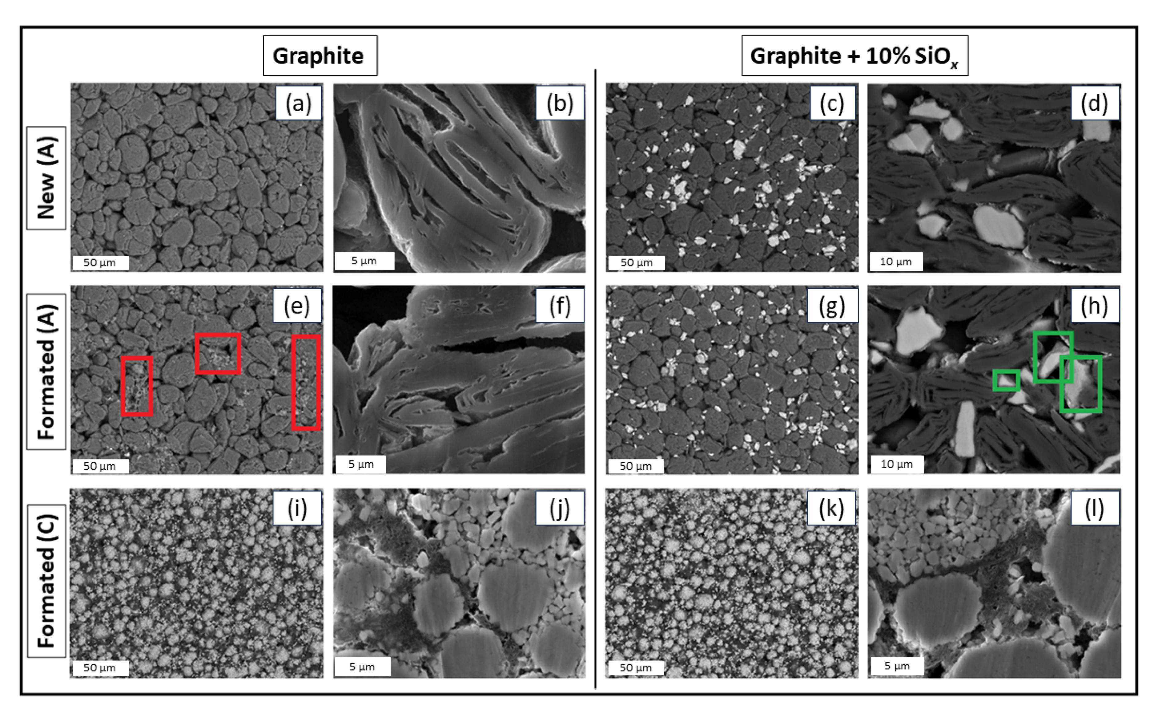
3.4. Chemical and Component Analysis

Table 3 shows the components and composition of the cells in new condition as well as after formation, separately for the anode and cathode. With the help of ICP-OES, the metal fractions in the electrodes could be analysed. The silicon content was determined via photometry and the gravimetrical composition was determined using TGA. The measured values are separated into mass loss in N 2 atmosphere (to determine organic components, e.g., binder shares and components of the SEI), mass loss in O 2 atmosphere (to analyse combustion via temperature, e.g., graphite, carbon black, or pyrolysis soot), and residue after the measurement (inactive components or reaction products like SiO 2 , Li 2 CO 3 , LiF, etc.) [35,36,37].
For the cathode, only small differences are measurable. The mass loss in an N 2 atmosphere increases after formation for all cells, presumably due to decomposition products from the formation. This can also be concluded by looking at the electrolyte degradation in Figure 4, where typical degradation gases can be found [33].
For the anodes, between new condition and after formation, the differences are more obvious. With increasing silicon content (i.e., SiO x ), more lithium is measured after formation in the anode via ICP-OES. This is due to an increased SEI formation on the surface of the Si(O x ) particles and the formation of an inactive Li 4 SiO 4 matrix [38,39,40]. The increased value for the graphite anode can be explained by the slight Li plating that was visible after the cell was opened [41].
After formation, the measured silicon content for every anode composition was reduced compared to the new state. Due to the conservation of mass, no silicon can be lost. The silicon from the SEI reactions and silicate formation can be found with photometry. The only explanation for a “loss” of silicon is the formation of gaseous products such as SiF 4 [13], which can also be seen in Figure 5 and cannot be detected in the solid phase anymore. As already stated in Section 3.3, continuous decomposition of electrolyte components such as conductive salts or solvents is happening alongside silicon aging, leading to formation of gaseous silicon species after the so-called hydrolitic cycle leading to gas evolution [12].
In Figure 8, SEM images of selected samples from the full cells after formation are shown. The first row (a−d) shows the results for the graphite-only anode and anode with 10 wt.% SiO x in new condition. The second row (e−h) shows the results for the graphite-only anode and anode with 10 wt.% SiO x after formation and the third row shows the results for the respective cathodes to the corresponding anodes of the full cell after formation. The electrode surface between the anodes in new condition and after formation ((a) vs. (e) and (c) vs. (g)) has slightly changed. Decomposition products can be recognised on the particle surfaces (marked in red in Figure 8e) and in Figure 8c, the bright SiO x particles appear darker, in contrast to Figure 8g.This is also a signal for increased decomposition products such as fluorine- and phosphorus-containing SEI components, which were also shown in previous publications with EDX measurements [9,25]. By comparing the SiO x particles in the cross-section SEM image in Figure 8d,h, a seam of decomposition products on the particle surface can also be seen (marked in green). By looking only at the SEM images of the cathodes, no visible aging or decomposition products can be identified.

4. Conclusions

In conclusion, this research study provides valuable insights into various aspects of lithium-ion cells with silicon oxide-containing anodes by conducting electrochemical measurements, analyzing thickness changes, investigating electrolyte degradation and gas evolution, as well as performing chemical and component analyses.
It can be stated that varying the silicon oxide content influences the charge and discharge curves of the cells. The increasing silicon oxide content leads to increased voltage hysteresis between charge and discharge mainly due to the fact that the lithiation and delithiation processes of graphite and silicon occur in parallel but in separate voltage regions. The FCE decreases with higher silicon content, primarily due to the irreversible formation of Li x Si y . Loss of active lithium from the cathode during formation processes further decreases the first-cycle efficiencies in the full-cell setup.
The anodes exhibit a steady increase in thickness during lithiation and a decrease during delithiation. The increasing silicon oxide content leads to a higher thickness change in the anodes, and the peaks in the DV curves correspond to specific anode active materials, i.e., match with them, and therefore dilations of graphite and silicon oxide during anode delithiation can be distinguished separately.
Supportive GC-MS analysis reveals evidence of silicon-containing gaseous fragments (dimethyl silane and fluorotrimethyl silane) as a result of Si aging. Detailed information on the intermediates of degradation, which provide information about the degradation pathways, were elaborated. The continuous electrolyte decomposition, as part of the hydrolytic cycle, is effectively illustrated. The silicon oxide content significantly influences degradation, with higher levels leading to increased gas formation in the anode.
The chemical−physical analyses of metal fractions, silicon content, and gravimetrical composition exhibit differences in the anodes and cathodes between the new condition and after formation. Mass loss in an N 2 atmosphere increases in the anodes after formation, potentially due to decomposition products from the formation process, which can be shown with the help of TGA. Increased SEI formation and inactive Li 4 SiO 4 matrix formation contribute to differences in lithium measurement in the anodes after formation. The silicon content decreases in the anodes after formation, indicating the formation of gaseous products such as SiF 4 . Electrolyte decomposition and silicon aging lead to the formation of gaseous silicon species and decomposition products on the electrode surfaces, as also shown with SEM analysis.
Overall, these findings emphasise the importance of a holistic view on aging processes when using silicon oxide-containing anodes. An understanding of the complex chemical changes in electrode materials is crucial for designing more efficient and durable lithium-ion cells.

Author Contributions

Conceptualisation, P.H.; methodology, P.H. and J.P.; validation, P.H. and J.P.; formal analysis, P.H. and J.P.; investigation, P.H. and J.P.; resources, P.H., F.K. and J.T.; data curation, P.H. and J.P.; writing—original draft preparation, P.H. and J.P.; writing—review and editing, P.H., J.P., F.K. and J.T.; visualisation, P.H.; supervision, F.K. and J.T.; project administration, P.H. and J.P.; funding acquisition, J.T. All authors have read and agreed to the published version of the manuscript.

Funding

This research was partly funded by the joint project OsabanPlus (03XP0469C) within the German–Japanese cooperation program of BMBF (Federal Ministry for Education and Research) and NEDO (New Energy and Industrial Technology Development Organization).

Institutional Review Board Statement

Not applicable.

Informed Consent Statement

Not applicable.

Data Availability Statement

Data will be available on request.

Acknowledgments

The authors thank Philipp Bellucci (Mercedes-Benz AG) for recording the SEM images, Kevin Gneupel (Fraunhofer ICT) for carrying out the GCMS analyses, and Martin Joos (Fraunhofer ICT) for helping with DEMS analyses. The authors also thank Wolfgang Märkle (Mercedes-Benz AG) and Michael Abert (Fraunhofer ICT) for the scientific exchange.

Conflicts of Interest

The authors declare no conflict of interest.

Abbreviations

The following abbreviations are used in this manuscript:
CBCarbon black
CCConstant current
CMCCarboxymethyl cellulose
CTSCell test system
CVConstant voltage
DCDifferential capacity
DCMMethylene chloride
DECDiethyl carbonate
DEMSDifferential electrochemical mass spectrometry
DMCDimethyl carbonate
DVDifferential voltage
EDXEnergy-dispersive X-ray spectroscopy
FCEFirst-cycle efficiency
FIDFlame ionisation detector
GCGas chromatography
GrGraphite
ICPInductively coupled plasma
LIBLithium-ion battery
MIDMultiple ion detection
MSMass spectrometry
NISTNational Institute of Standards and Technology
NMCNickel–manganese–cobalt
OESOptical emission spectrometry
PVDFPolyvinylidene fluoride
SBRStyrene butadiene rubber
SEISolid electrolyte interface
SEMSurface electron microscopy
SiO x Silicon oxide
SOCState of charge
TCDThermal conductivity detector
TGAThermogravimetric analysis
TICTotal ion current

References

  1. Ziegler, M.S.; Trancik, J.E. Re-examining rates of lithium-ion battery technology improvement and cost decline. Energy Environ. Sci. 2021, 14, 1635–1651. [Google Scholar] [CrossRef]
  2. Jin, Y.; Zhu, B.; Lu, Z.; Liu, N.; Zhu, J. Challenges and Recent Progress in the Development of Si Anodes for Lithium-Ion Battery. Adv. Energy Mater. 2017, 7, 1700715. [Google Scholar] [CrossRef]
  3. Moyassari, E.; Roth, T.; Kücher, S.; Chang, C.C.; Hou, S.C.; Spingler, F.B.; Jossen, A. The Role of Silicon in Silicon-Graphite Composite Electrodes Regarding Specific Capacity, Cycle Stability, and Expansion. J. Electrochem. Soc. 2022, 169, 010504. [Google Scholar] [CrossRef]
  4. Edge, J.S.; O’Kane, S.; Prosser, R.; Kirkaldy, N.D.; Patel, A.N.; Hales, A.; Ghosh, A.; Ai, W.; Chen, J.; Yang, J.; et al. Lithium ion battery degradation: What you need to know. Phys. Chem. Chem. Phys. 2021, 23, 8200–8221. [Google Scholar] [CrossRef] [PubMed]
  5. Obrovac, M.N.; Christensen, L. Structural Changes in Silicon Anodes during Lithium Insertion/Extraction. Electrochem. Solid-State Lett. 2004, 7, A93. [Google Scholar] [CrossRef]
  6. Chen, T.; Wu, J.; Zhang, Q.; Su, X. Recent advancement of SiOx based anodes for lithium-ion batteries. J. Power Sources 2017, 363, 126–144. [Google Scholar] [CrossRef]
  7. Louli, A.J.; Li, J.; Trussler, S.; Fell, C.R.; Dahn, J.R. Volume, Pressure and Thickness Evolution of Li-Ion Pouch Cells with Silicon-Composite Negative Electrodes. J. Electrochem. Soc. 2017, 164, A2689–A2696. [Google Scholar] [CrossRef]
  8. Wang, X.; Zhu, J.; Dai, H.; Yu, C.; Wei, X. Impedance Investigation of Silicon/Graphite Anode during Cycling. Batteries 2023, 9, 242. [Google Scholar] [CrossRef]
  9. Heugel, P.; Märkle, W.; Deich, T.; von Kessel, O.; Tübke, J. Thickness change and jelly roll deformation and its impact on the aging and lifetime of commercial 18650 cylindrical Li-ion cells with silicon containing anodes and nickel-rich cathodes. J. Energy Storage 2022, 53, 105101. [Google Scholar] [CrossRef]
  10. Zhang, L.; Tsolakidou, C.; Mariyappan, S.; Tarascon, J.M.; Trabesinger, S. Unraveling gas evolution in sodium batteries by online electrochemical mass spectrometry. Energy Storage Mater. 2021, 42, 12–21. [Google Scholar] [CrossRef]
  11. Holzapfel, M.; Würsig, A.; Scheifele, W.; Vetter, J.; Novák, P. Oxygen, hydrogen, ethylene and CO2 development in lithium-ion batteries. J. Power Sources 2007, 174, 1156–1160. [Google Scholar] [CrossRef]
  12. McBrayer, J.D.; Rodrigues, M.T.F.; Schulze, M.C.; Abraham, D.P.; Apblett, C.A.; Bloom, I.; Carroll, G.M.; Colclasure, A.M.; Fang, C.; Harrison, K.L.; et al. Calendar aging of silicon-containing batteries. Nat. Energy 2021, 6, 866–872. [Google Scholar] [CrossRef]
  13. Seitzinger, C.L.; Sacci, R.L.; Coyle, J.E.; Apblett, C.A.; Hays, K.A.; Armstrong, R.R.; Rogers, A.M.; Armstrong, B.L.; Bennet, T.H.; Neale, N.R.; et al. Intrinsic Chemical Reactivity of Silicon Electrode Materials: Gas Evolution. Chem. Mater. 2020, 32, 3199–3210. [Google Scholar] [CrossRef]
  14. Yao, K.P.C.; Okasinski, J.S.; Kalaga, K.; Almer, J.D.; Abraham, D.P. Operando Quantification of (De)Lithiation Behavior of Silicon–Graphite Blended Electrodes for Lithium–Ion Batteries. Adv. Energy Mater. 2019, 9, 1803380. [Google Scholar] [CrossRef]
  15. Berhaut, C.L.; Dominguez, D.Z.; Kumar, P.; Jouneau, P.H.; Porcher, W.; Aradilla, D.; Tardif, S.; Pouget, S.; Lyonnard, S. Multiscale Multiphase Lithiation and Delithiation Mechanisms in a Composite Electrode Unraveled by Simultaneous Operando Small-Angle and Wide-Angle X-ray Scattering. ACS Nano 2019, 13, 11538–11551. [Google Scholar] [CrossRef]
  16. Zilberman, I.; Sturm, J.; Jossen, A. Reversible self-discharge and calendar aging of 18650 nickel-rich, silicon-graphite lithium-ion cells. J. Power Sources 2019, 425, 217–226. [Google Scholar] [CrossRef]
  17. Sturm, J.; Rheinfeld, A.; Zilberman, I.; Spingler, F.B.; Kosch, S.; Frie, F.; Jossen, A. Modeling and simulation of inhomogeneities in a 18650 nickel-rich, silicon-graphite lithium-ion cell during fast charging. J. Power Sources 2019, 412, 204–223. [Google Scholar] [CrossRef]
  18. Kreissl, J.J.A.; Petit, J.; Oppermann, R.; Cop, P.; Gerber, T.; Joos, M.; Abert, M.; Tübke, J.; Miyazaki, K.; Abe, T.; et al. Electrochemical Lithiation/Delithiation of ZnO in 3D-Structured Electrodes: Elucidating the Mechanism and the Solid Electrolyte Interphase Formation. ACS Appl. Mater. Interfaces 2021, 13, 35625–35638. [Google Scholar] [CrossRef]
  19. The NIST Mass Spectral Search Program, version 2.3; National Institute of Standards and Technology: Gaithersburg, MD, USA, 2017.
  20. Ai, W.; Kirkaldy, N.; Jiang, Y.; Offer, G.; Wang, H.; Wu, B. A composite electrode model for lithium-ion batteries with silicon/graphite negative electrodes. J. Power Sources 2022, 527, 231142. [Google Scholar] [CrossRef]
  21. Obrovac, M.N.; Chevrier, V.L. Alloy negative electrodes for Li-ion batteries. Chem. Rev. 2014, 114, 11444–11502. [Google Scholar] [CrossRef]
  22. Chevrier, V.L.; Dahn, J.R. First Principles Model of Amorphous Silicon Lithiation. J. Electrochem. Soc. 2009, 156, A454. [Google Scholar] [CrossRef]
  23. Zhang, W.J. Lithium insertion/extraction mechanism in alloy anodes for lithium-ion batteries. J. Power Sources 2011, 196, 877–885. [Google Scholar] [CrossRef]
  24. Safari, M.; Morcrette, A.; Teyssot, A.; Delacort, C. Multimodal Physics-Based Aging Model for Life Prediction of Li-Ion Batteries. J. Electrochem. Soc. 2009, 156, A145. [Google Scholar] [CrossRef]
  25. Bazlen, S.; Heugel, P.; von Kessel, O.; Commerell, W.; Tübke, J. Influence of charging protocols on the charging capability and aging of lithium-ion cells with silicon-containing anodes. J. Energy Storage 2022, 49, 104044. [Google Scholar] [CrossRef]
  26. Ohzuku, T.; Iwakoshi, Y.; Sawai, K. Formation of Lithium–Graphite Intercalation Compounds in Nonaqueous Electrolytes and Their Application as a Negative Electrode for a Lithium Ion (Shuttlecock) Cell. J. Electrochem. Soc. 1993, 140, 2490. [Google Scholar]
  27. Schweidler, S.; de Biasi, L.; Schiele, A.; Hartmann, P.; Brezesinski, T.; Janek, J. Volume Changes of Graphite Anodes Revisited: A Combined Operando X-ray Diffraction and In Situ Pressure Analysis Study. J. Phys. Chem. C 2018, 122, 8829–8835. [Google Scholar] [CrossRef]
  28. Spingler, F.B.; Kücher, S.; Phillips, R.; Moyassari, E.; Jossen, A. Electrochemically Stable In Situ Dilatometry of NMC, NCA and Graphite Electrodes for Lithium-Ion Cells Compared to XRD Measurements. J. Electrochem. Soc. 2021, 168, 040515. [Google Scholar] [CrossRef]
  29. von Kessel, O.; Hoehl, T.; Heugel, P.; Brauchle, F.; Vrankovic, D.; Birke, K.P. Electrochemical-Mechanical Parameterization and Modeling of Expansion, Pressure, and Porosity Evolution in NMC811|SiOx-Graphite Lithium-Ion Cells. J. Electrochem. Soc. 2023. [Google Scholar] [CrossRef]
  30. Yang, Z.; Trask, S.E.; Wu, X.; Ingram, B.J. Effect of Si Content on Extreme Fast Charging Behavior in Silicon–Graphite Composite Anodes. Batteries 2023, 9, 138. [Google Scholar] [CrossRef]
  31. Peschel, C.; Horsthemke, F.; Leißing, M.; Wiemers-Meyer, S.; Henschel, J.; Winter, M.; Nowak, S. Analysis of Carbonate Decomposition During Solid Electrolyte Interphase Formation in Isotope–Labeled Lithium Ion Battery Electrolytes: Extending the Knowledge about Electrolyte Soluble Species. Batter. Supercaps 2020, 3, 1183–1192. [Google Scholar] [CrossRef]
  32. Rinkel, B.L.D.; Hall, D.S.; Temprano, I.; Grey, C.P. Electrolyte Oxidation Pathways in Lithium-Ion Batteries. J. Am. Chem. Soc. 2020, 142, 15058–15074. [Google Scholar] [CrossRef]
  33. Han, J.G.; Kim, K.; Lee, Y.; Choi, N.S. Scavenging Materials to Stabilize LiPF6-Containing Carbonate-Based Electrolytes for Li-Ion Batteries. Adv. Mater. 2019, 31, e1804822. [Google Scholar] [CrossRef]
  34. Hasa, I.; Haregewoin, A.M.; Zhang, L.; Tsai, W.Y.; Guo, J.; Veith, G.M.; Ross, P.N.; Kostecki, R. Electrochemical Reactivity and Passivation of Silicon Thin-Film Electrodes in Organic Carbonate Electrolytes. ACS Appl. Mater. Interfaces 2020, 12, 40879–40890. [Google Scholar] [CrossRef]
  35. Heiskanen, S.K.; Kim, J.; Lucht, B.L. Generation and Evolution of the Solid Electrolyte Interphase of Lithium-Ion Batteries. Joule 2019, 3, 2322–2333. [Google Scholar] [CrossRef]
  36. Pender, J.P.; Jha, G.; Youn, D.H.; Ziegler, J.M.; Andoni, I.; Choi, E.J.; Heller, A.; Dunn, B.S.; Weiss, P.S.; Penner, R.M.; et al. Electrode Degradation in Lithium-Ion Batteries. ACS Nano 2020, 14, 1243–1295. [Google Scholar] [CrossRef]
  37. Kim, S.H.; Dong, K.; Zhao, H.; El-Zoka, A.A.; Zhou, X.; Woods, E.V.; Giuliani, F.; Manke, I.; Raabe, D.; Gault, B. Understanding the Degradation of a Model Si Anode in a Li-Ion Battery at the Atomic Scale. J. Phys. Chem. Lett. 2022, 13, 8416–8421. [Google Scholar] [CrossRef]
  38. Yamada, Y.; Iriyama, Y.; Abe, T.; Ogumi, Z. Kinetics of Electrochemical Insertion and Extraction of Lithium Ion at SiO. J. Electrochem. Soc. 2010, 157, A26. [Google Scholar] [CrossRef]
  39. Nagao, Y.; Sakaguchi, H.; Honda, H.; Funkunaga, T. Structural Analysis of Pure and Electrochemically Lithiated SiO Using Neutron Elastic Scattering. J. Electrochem. Soc. 2004, 151, A1572. [Google Scholar] [CrossRef]
  40. Miyachi, M.; Yamamoto, H.; Kawai, H.; Ohta, T. Analysis of SiO Anodes for Lithium-Ion Batteries. J. Electrochem. Soc. 2005, 152, A2089–A2091. [Google Scholar] [CrossRef]
  41. Daubinger, P.; Schelter, M.; Petersohn, R.; Nagler, F.; Hartmann, S.; Herrmann, M.; Giffin, G.A. Impact of Bracing on Large Format Prismatic Lithium–Ion Battery Cells during Aging. Adv. Energy Mater. 2022, 12, 2102448. [Google Scholar] [CrossRef]
Figure 1. Influence of different SiO x proportions in the anode on the charge and discharge curves (and their derivatives) of the full cells and their respective half cells after formation. The first line (ad) shows the curves for the full cells, which are obtained from the respective curves of the anodes (eh) and cathodes (il).
Batteries 09 00449 g001
Figure 2. First-cycle efficiency (FCE) for the anodes and NMC622 cathode used, determined from half-cell measurements against Li/Li + (a) and from full-cell measurements (b). Additionally, in (b): anode delithiation end voltage, measured with reference electrode and marked with black dots.
Batteries 09 00449 g002
Figure 3. Dilatometer measurements of the electrodes described in Table 1. Half-cell measurements against Li/Li + . (a,b): Change in thickness of the examined anodes with different SiO x contents for (a) lithiation and (b) delithiation. (c,d): Thickness change of the used NMC622 cathode for (c) delithiation and (d) lithiation. The differential voltage is plotted in each case (solid curves) on the left y-axis and the thickness change in % (dashed curves), compared to the initial state, on the right y-axis, versus the SOC of the respective electrode. The associated charging and discharging curves are shown in Figure 1.
Batteries 09 00449 g003
Figure 4. Representative GC-MS chromatogram after cell formation according to Section 2.2.1 for laboratory full cell with 25 wt.-% SiO x -containing graphite anode and NMC622 cathode according to Table 1.
Batteries 09 00449 g004
Figure 5. Voltage curves and operando DEMS analysis of selected masses. Mass signals of PO x F y (a), PF x (b), silane (c), and SiF 4 (d) for the cell containing 25 wt.-% SiO x . The voltage is plotted on the left y-axis and the ion current of the respective mass signal on the right y-axis, each over time on the x-axis. Each mass signal is indicated by a different colour.
Batteries 09 00449 g005
Figure 6. Voltage curves and operando DEMS analysis of selected masses for cells with varying SiO x contents. (a) 0 wt.-% SiO x , (b) 5 wt.-% SiO x , (c) 10 wt.-% SiO x , (d) 25 wt.-% SiO x . Each mass signal indicated by a different colour.
Batteries 09 00449 g006
Figure 7. Associated single-mass signals of selected species from DEMS measurements. (a) PO x F y (m/z = 104), (b) PF x (m/z = 58), (c) silane (m/z = 77), (d) solvent (DEC, m/z = 45) for varying SiO x contents (0−25 wt.-%).
Batteries 09 00449 g007
Figure 8. SEM images of new and formated anodes (A) and cathodes (C) harvested from full cells. The two left columns (a,b,e,f,i,j) show images of the electrodes that only contain graphite as the anode active material. The electrodes shown in the right two columns (c,d,g,h,k,l), contain 10% SiO x in addition to graphite in the anode. The top row shows the new, unformed electrodes, the middle row shows the results of the formed anodes, and the bottom row shows SEM images of the associated formatted cathodes. Decomposition products on the anode surface of the graphite-only anode are marked in red and on the SiO x particles of the anode containing 10 wt.-% SiO x , in green.
Batteries 09 00449 g008
Table 1. Composition and parameters of the electrodes used. Average of at least three electrodes coated one-sided and at least six measuring points per electrode.
Anode
GrSiO x CMCSBRCBThicknessPorosity
wt.-%µm%
Graphite94.00.02.02.02.07639.42
2.5 SiO x 91.52.52.02.02.06840.13
5 SiO x 89.05.02.02.02.06337.80
7.5 SiO x 86.57.52.02.02.06038.29
10 SiO x 84.010.02.02.02.05637.37
25 SiO x 69.025.02.02.02.04539.35
Cathode
NMCPVDFCB ThicknessPorosity
wt.-%µm%
NMC62294.03.03.0 7329.00
Table 2. First-cycle efficiency for the anodes and NMC622 cathode used according to Figure 2.
Half CellFull Cell
FCE
%
Graphite92.9789.97
2.5 SiO x 91.8787.84
5 SiO x 90.6986.66
7.5 SiO x 89.8985.86
10 SiO x 89.4184.39
NMC62290.87-
Table 3. Chemical–physical analyses of different laboratory tests in full-cell format with different SiO x contents, both in the new condition as well as the formatted condition. Results from ICP-OES measurements, silicon determination using photometry, and thermogravimetric analysis for anodes and cathodes separately.
NewAfter Formation
Anode
Gr2.5%5%7.5%10%Gr2.5%5%7.5%10%
ICPLithiumwt.-%<0.01<0.01<0.01<0.01<0.011.000.830.871.041.16
Nickel<0.01<0.01<0.01<0.01<0.01<0.01<0.01<0.01<0.01<0.01
Manganese<0.01<0.01<0.01<0.01<0.01<0.01<0.01<0.01<0.01<0.01
Cobalt<0.02<0.02<0.02<0.02<0.02<0.02<0.02<0.02<0.02<0.02
Phosphorus<0.02<0.02<0.02<0.02<0.020.030.030.030.030.04
PhotometrySilicon01.2632.4463.7114.95501.1652.3693.4934.620
TGAin N 2 2.82.62.62.62.63.22.92.62.42.0
in O 2 96.793.790.989.185.695.592.088.485.482.9
Residue0.63.76.48.111.81.45.08.012.215.1
Cathode
TGAin N 2 wt.-%5.15.15.15.15.18.07.57.67.97.7
in O 2 0.50.50.50.50.50.20.20.20.20.2
Residue94.394.394.394.394.391.792.492.292.192.1
Disclaimer/Publisher’s Note: The statements, opinions and data contained in all publications are solely those of the individual author(s) and contributor(s) and not of MDPI and/or the editor(s). MDPI and/or the editor(s) disclaim responsibility for any injury to people or property resulting from any ideas, methods, instructions or products referred to in the content.

