Abstract
In this study, we are reporting the impact of the incorporation of ferroelectric nanoparticles (FNPs), such as BaTiO3 (BTO), BiFeO3 (BFO), Bi4NdTi3Fe0.7Ni0.3O15 (BNTFN), and Bi4NdTi3Fe0.5Co0.5O15 (BNTFC), as well as the mass loading of sulfur to fabricated solvent-free sulfur/holey graphene-carbon black/polyvinylidene fluoride (S/FNPs/CBhG/PVDF) composite electrodes to achieve high areal capacity for lithium-sulfur (Li-S) batteries. The dry-press method was adopted to fabricate composite cathodes. The hG, a conductive and lightweight scaffold derived from graphene, served as a matrix to host sulfur and FNPs for the fabrication of solvent-free composites. Raman spectra confirmed the dominant hG framework for all the composites, with strong D, G, and 2D bands. The surface morphology of the fabricated cathode system showed a homogeneous distribution of FNPs throughout the composites, confirmed by the EDAX spectra. The observed Li+ ion diffusion coefficient for the composite cathode started at 2.17 × 10⁻¹⁶ cm2/s (S25(CBhG)65PVDF10) and reached up to the highest value (4.15 × 10⁻¹⁵ cm2/s) for S25BNTFC5(CBhG)60PVDF10. The best discharge capacity values for the S25(CBhG)65PVDF10 and S25BNTFC5(CBhG)60PVDF10 composites started at 1123 mAh/gs and 1509 mAh/gs and dropped to 612 mAh/gs and 572 mAh/gs, respectively, after 100 cycles; similar behavior was exhibited by the other composites that were among the best. These are better values than those previously reported in the literature. The incorporation of ferroelectric nanoparticles in the cathodes of Li-S batteries reduced the rapid formation of polysulfides due to their internal electric fields. The areal capacity for the S25(CBhG)65PVDF10 composites was 4.84 mAh/cm2 with a mass loading of 4.31 mgs/cm2, while that for the S25BNTFC5(CBhG)60PVDF10 composites was 6.74 mAh/cm2 with a mass loading of 4.46 mgs/cm2. It was confirmed that effective FNP incorporation within the S cathode improves the cycling response and stability of cathodes, enabling the high performance of Li-S batteries.
1. Introduction
Li-S rechargeable batteries with high-energy capacity are considered one of the most promising energy storage systems for electronic devices and electric vehicles [1]. These Li-S batteries have the following advantages: low cost, low operating voltage (2.2 V), environmentally friendly, good energy storage system due to their higher theoretical energy density (2600 Wh/kg), and theoretical specific capacity (1675 mAh/g) [2,3,4,5,6]. On the other hand, Li-S batteries present a disadvantage since they possess low cyclability [7]. These challenges can be dealt with by adding a carrier material with a rich pore structure to adsorb lithium polysulfides and chemisorption [8,9], limiting the dissolution and diffusion of lithium polysulfide between polar carrier materials and lithium polysulfides (LiPs) [10]. The insulating nature of sulfur still limits the development of high-loading sulfur cathodes with sufficient sulfur content, and most existing cathodes have low sulfur loadings (<2 mg/cm2) and contents (<60 wt%) [11]. To address these problems, porous substrates with various functions have emerged as effective sulfur hosts that can prevent the rapid loss of large amounts of polysulfides, especially at increased sulfur loadings. To improve the sulfur conductivity and loading area, porous carbon materials are applied. The pore structure enhances sulfur loading and promotes fast ion diffusion. Furthermore, the capillary effect of the elemental sulfur-filled pores can effectively inhibit the diffusion of LiPs into the electrolyte, slow down the shuttle effect, and increase the utilization rate of active materials to improve the energy density of Li-S batteries. Various synthesis strategies of S-doped carbon as electrode materials for energy storage applications have been reported [12], including thermal treatment [13], hydrothermal methods [14], biomass-assisted synthesis [15], polymer-assisted synthesis [16], template-assisted synthesis [17], microwave-assisted synthesis [18], solvothermal methods [19], sol-gel processing [20], chemical vapor deposition [21], and sublimation [22]. Song and coworkers [23] synthesized highly crumpled nitrogen-doped graphene (NG) with an ultrahigh pore volume and large surface area, enabling strong LiPs adsorption and high sulfur content and areal loading in the NG host; they reported a high capacity of ≈1000 mAh/g with 80 wt% sulfur content and a high sulfur loading of 5 mg/cm2. Ferroelectric nanoparticles (FNPs) exhibiting spontaneous polarization provide strong interactions with electric fields [24], having the ability to suppress shuttle effects in sulfur cathodes. FNPs in cathodes eliminate the concentration gradient of Li-ions near the deposition surface, yielding diffusion pathways in electrolyte/active material and accelerating the transfer speed of Li-ions. In commercial batteries, the areal capacity density of cathodes is generally higher than 2.0 mAh/cm2, with an average output voltage of 3.5 V. However, the areal capacity density of sulfur cathodes is higher than 3.3 mAh/cm2, considering the average voltage of 2.1 V for Li-S batteries [25]. Moreover, for electric vehicle (EV) applications, to deliver a mileage of more than 300 miles, an aerial capacity of 5 mAh/cm2 and energy density of 500 Wh/kg are required to support their practical power output requirements, due to which high sulfur loading and utilization are needed to achieve the high areal capacity and high energy density of Li-S batteries [26,27]. We recently demonstrated that the hG framework greatly improves the performance of electrodes, facilitating the active material to fully participate in electrochemical reactions [28]. Ferroelectrics have strong polarization and can assist polysulfides chemisorption and alter Li+ diffusion. The uniform distribution of ferroelectrics is expected to contribute to enhanced affinity to polysulfides in the overall cell system [29,30]. Moreover, the C/S + BTO composite exhibits a higher initial discharge capacity of 1143 mAh/g at 0.2 C after 100 cycles; for the C/S electrode without BTO nanoparticles, a discharge capacity of 407 mAh/g can be obtained after 100 cycles [31]. In 2019, a unique “black” B-BTO was developed for the first time as a multifunctional sulfur immobilizer to improve performance and facilitate high conductivity with electron transfer and kinetics with sulfur reaction in this type of battery [32]. The bismuth ferrite BiFeO3 (BFO) incorporated into cathodes reduced the impact of polysulfide shuttle and improved cyclic stability. The cathode capacity of the S60BFO30C10 composite Li-S battery reached ~1600 mAh/g, and the cell operated for up to 30 cycles [33]. In most studies of Li-S batteries, the ferroelectric nanoparticle materials were incorporated into the separator or cathode of devices. In Table 1, we make a comparison between these studies and our work in terms of capacity retention, cyclability, initial specific capacity, and Coulombic efficiency [29,31,32,33,34,35]. We achieved a much better overall performance in relation to these studies. In this study, we are presenting the effect of the mass loading and coupling of different FNPs such as BTO, BFO, BNTFN, and BNTFC on hG/S composites to achieve high areal capacity in Li-S cathodes.

Table 1.
Comparison of reported results on incorporated ferroelectric materials in Li-S batteries regarding initial specific capacity, cyclability, capacity retention, and Coulombic efficiency of separator and cathode compositions.
2. Materials, Methods, and Characterizations
Materials. In this work, the hG was prepared from graphene (Vorbeck materials) using the established one-step air oxidation procedure previously reported [36]. Bis(trifluoromethylsulfonyl)imide lithium salt (LiTFSI; 98+%), lithium nitrate (LiNO3; 99.99%), 1,2-dimethoxyethane (DME; 99+%), and 1,3-dioxolane (DOL; 99.5%) were purchased from Thermo Fisher (Waltham, MA, USA) * (* Specific vendor and manufacturer names do not imply an endorsement by the authors, nor does it imply that the specified material or equipment is the best available.). Sulfur (S; 99.998%), highly pure barium carbonate (BaCO3; 99.8%), neo-dymium (III) oxide (Nd2O3; 99.9%), lithium foil (0.75 mm thick × 19 mm wide) (Al; 99.9%), high-purity cobalt (II, III) oxide (Co3O4; 99.998%), polyvinylidene fluoride (PVDF), and carbon back (CB) were purchased from Alfa Aesar (Haverhill, MA, USA) * (* Specific vendor and manufacturer names do not imply an endorsement by the authors, nor does it imply that the specified material or equipment is the best available.). Iron oxide (Fe2O3; 99.998%), nickel (III) oxide nanopowder (Ni2O3; 99%), and Celgard membrane (25 μm thickness and 85 mm width) were purchased from Sigma-Aldrich (St. Louis, MO, USA) * (* Specific vendor and manufacturer names do not imply an endorsement by the authors, nor does it imply that the specified material or equipment is the best available.). High-purity bismuth oxide (Bi2O3; 99.9%) was purchased from Fluka and titanium dioxide (TiO2; 97%) was purchased from Fisher Scientific * (* Specific vendor and manufacturer names do not imply an endorsement by the authors, nor does it imply that the specified material or equipment is the best available). All precursors and elements for the battery assembly were used inside the glove box with argon-filled water (H2O) and oxygen (O2) contents < 0.5 ppm.
Synthesis of ferroelectric nanoparticles. The FNPs were synthesized via mechanical activation followed by thermal treatment. Stoichiometric amounts of 15 wt% excess of Bi2O3 were used to compensate for volatilization loss during the thermal treatment. The oxides were mixed with isopropanol using a high-energy ball-milling planetary machine with zirconia balls (Across International, PQ-N04 Planetary Ball Mill, San Juan, PR, USA) operating at 45 Hz (2700 rpm) for 8 hrs. The synthesized material was dried on a hot plate at 100 °C for 8 hrs. We used a furnace (Carbolite, HTF1700, San Juan, PR, USA) at a heating and cooling rate of 5 °C/min in which the powders were calcined.
Sulfur-FNPs-holey graphene/carbon black-PVDF composite cathode preparation and characterizations. In a typical experiment to prepare S25(CBhG)65PVDF10 and S25FNPs5(CB98.5%hG1.5%)60PVDF10 composite cathodes, individual powder was mixed in a particular ratio by using ball milling to fabricate composite electrodes of S25(CB98.5%hG1.5%)65PVDF10 and S25FNPs5(CB98.5%hG1.5%)60PVDF10. For each sample, a 100 mg composite was prepared in the desirable amount of S, CBhG, FNP, and PVDF powders (weight ratios of 2.5:0.0:6.5:1.0 and 2.5:0.5:6.0:1.0 for a total of five different samples) and loaded in a 50 mL zirconia vial. After placing two zirconia balls in the vial, the set was secured in PQ-N04 series planetary ball mills and milled for 10–15 s to yield the S25(CBhG)65PVDF10 and S25FNPs5(CB98.5%hG1.5%)60PVDF10 composites. The PVDF was used as a binder and the d CB was used as a conductor to improve the electrical conductivity and cycle life of the active material. PVDF as a binder helps counter volumetric changes occurring in the insertion electrodes during intercalation/deintercalation and ensures adhesion to the current collectors, which is useful for the stability of the electrodes. The fabrication of composite cathodes using the dry-press method is facile and does not require the use of solvents. The hG can be compressed from its dry powder form into solid architectures of various shapes [37,38,39]. For the fabrication of the electrode disc, 20 mg of the material was added to a 13 mm diameter stainless-steel pressing die. The pressed powders were directly used as the composite cathodes S25(CBhG)65PVDF10 and S25FNPs5(CBhG)60PVDF10, while the polypropylene membrane was used as a separator and lithium foil was used as an anode for assembling the coin cells (CR2032). To prepare the electrolyte, 1 M of LiTFSI and 0.2 M of LiNO3 were dissolved in DOL/DME (1:1, v/v). To calculate the proper amount of electrolyte (40 uL), we used 5.72 mgs of the active mass with cathode loadings of 7 mL/gs. This technique facilitates preparation, and it is less time-consuming than conventional solvent-based methods. Table 2 summarizes the critical cell parameters, such as sulfur content, sulfur loading, and electrolyte-to-sulfur ratios. A powder X-ray diffractometer was used for structure, scanning electron microscopy was used for the surface morphology of the electrodes, Raman spectroscopy was performed for the electronic structure, and galvanostatic discharge-charge curves were collected using a battery tester. A detailed description of FNP synthesis and intercalation inside a sulfur cathode and FNP characterization was provided in the article “Holey Graphene/Ferroelectric/Sulfur Composite Cathodes for High-Capacity Lithium-Sulfur Batteries”, published in ACS Omega by the authors [35].
Table 2.
Critical cell parameters.
3. Results and Discussion
Figure 1a–e shows the X-ray diffraction (XRD) spectra of the S25(CBhG)65PVDF10 and S25FNPs5(CBhG)60PVDF10 composites. The XRD analysis was performed to investigate structural changes due to the incorporation of materials such as BTO [37], BFO [40], BNTFN [41], and BNTFC [42] and their possible reactions with S, CB, hG, and PVDF. As shown in Figure 1, the prominent peak of hkl (222) at 2θ = 23° corresponded to the Fddd orthorhombic structure of S (JCPDS no. 08-0247) [43,44]. The peak planes of (002) and (101) were at 2θ = 25° and 43° (attributed to carbon materials CB or hG), respectively; however, the (110) plane at 2θ = 27° corresponded to PVDF. These peaks were detected in all cathode compounds demonstrating the presence of all the aforementioned materials. Furthermore, the rest of the identified peaks could be perfectly indexed with their respective miller indices in the XRD spectra corresponding to the FNPs.
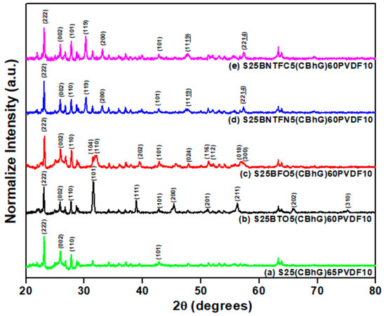
Figure 1.
XRD spectra of (a) S25(CBhG)65PVDF10, (b) S25BTO5(CBhG)60PVDF10, (c) S25BFO5(CBhG)60PVDF10, (d) S25BNTFN5(CBhG)60PVDF10, and (e) S25BNTFC5(CBhG)60PVDF10 composites.
Figure 2a–e shows the Raman spectra for the S25(CBhG)65PVDF10 and S25FNPs5(CBhG)60PVDF10 composites. The pronounced D band (disorder-induced phonon mode) at approximately 1336 cm−1 and G band (associated with in-plane vibration of the graphite lattice) at approximately 1575 cm−1 suggest a graphite-like carbon framework [45,46]. The intensity ratios (ID/IG) shown in Figure 2a (ID/IG was 1.06 for S/CBhG/PVDF), Figure 2b (ID/IG was 1.10 for S/BTO/CBhG/PVDF), Figure 2c (ID/IG was 1.01 for S/BFO/CBhG/PVDF), Figure 2e (ID/IG was 1.00 for S/BNTFC/CBhG/PVDF), and Figure 2d (ID/IG was 0.97 for S/BNTFN/CBhG/PVDF) were slightly reduced, presumably due to defect removal through the combined effects of ferroelectric nanoparticles doping. The Raman peaks for 2D and D + G were also visible at approximately 2700 cm−1, this was attributed to the layered structure of the graphene.
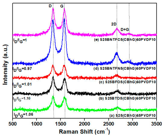
Figure 2.
Raman spectra of (a) S25(CBhG)65PVDF10, (b) S25BTO5(CBhG)60PVDF10, (c) S25BFO5(CBhG)60PVDF10, (d) S25BNTFN5(CBhG)60PVDF10, and (e) S25BNTFC5(CBhG)60PVDF10 composites.
Figure 3a–e shows SEM images of the S25(CBhG)65PVDF10 and S25FNPs5(CBhG)60PVDF10 composites. It is clear from Figure 3a–e that BTO, BFO, BNTFN, and BNTFC ferroelectric nanoparticles; carbon black; holey graphene; and sulfur were well mixed in the composites. The composite surface was smooth, which confirmed that the sulfur had dispersed in the hG framework very well. The holey graphene and CB acted as efficient electron transport carriers to ensure good electrical contact within the composites. The layered structures provided sufficient space to effectively absorb electrolytes, and buffering the volume expansion of the sulfur helped ensure sufficient electrochemical reactions and excellent cycling performance [46].
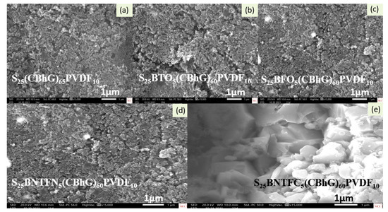
Figure 3.
SEM images of (a) S25(CBhG)65PVDF10, (b) S25BTO5(CBhG)60PVDF10, (c) S25BFO5(CBhG)60PVDF10, (d) S25BNTFN5(CBhG)60PVDF10, and (e) S25BNTFC5(CBhG)60PVDF10 composites with magnification of ×15000 at 1 μm.
Figure 4 shows the EDS spectra of the S25(CBhG)65PVDF10 and S25FNPs5(CBhG)60PVDF10 composites. In each spectrum, the S-peak was dominant due to its higher concentration relative to the carbon black, hG, PVDF, BiFeO3, BaTiO3, Bi4NdTi3Fe0.7Ni0.3O15, and Bi4NdTi3Fe0.5Co0.5O15, although the observed peaks clearly indicated their presence.
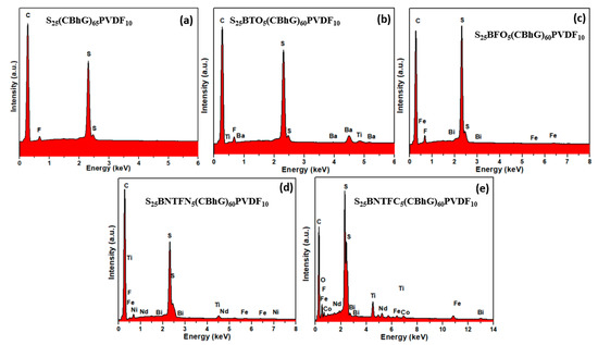
Figure 4.
EDS of (a) S25(CBhG)65PVDF10, (b) S25BTO5(CBhG)60PVDF10, (c) S25BFO5(CBhG)60PVDF10, (d) S25BNTFN5(CBhG)60PVDF10, and (e) S25BNTFC5(CBhG)60PVDF10 composites.
Figure 5 shows the Nyquist plots for the S25(CBhG)65PVDF10, S25BTO5(CBhG)60PVDF10, S25BNTFN5(CBhG)60PVDF10, and S25BNTFC5(CBhG)60PVDF10 composites. The Nyquist plot of the S25BFO5(CBhG)60PVDF10 composite is shown in the inset for clarity. All the EIS spectra showed depressed semicircles in the high-frequency region, corresponding to the charge-transfer process, and a sloping straight line in the low-frequency region was consistent with the semi-infinite Warburg diffusion process [45,46].
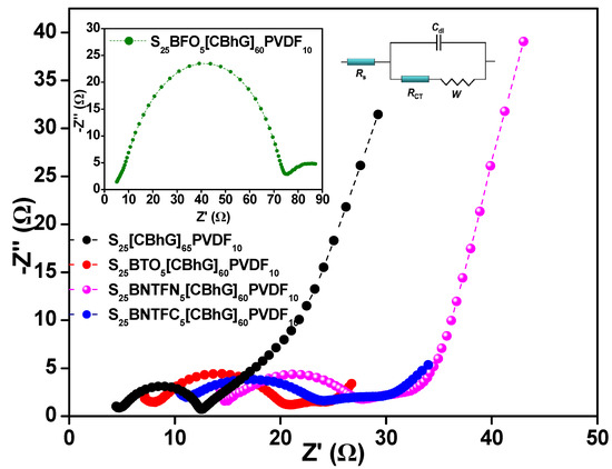
Figure 5.
Nyquist plot comparison from electrochemical impedance spectroscopy spectrum measurements before charge-discharge of all battery cells with S25(CBhG)65PVDF10, S25BTO5(CBhG)60PVDF10, S25BFO5(CBhG)60PVDF10 (inset), S25BNTFN5(CBhG)60PVDF10, and S25BNTFC5(CBhG)60PVDF10 cathodes of studies from 1 MHz to 0.1 Hz at room temperature with circuit model.
The EIS spectra before charge-discharge for all batteries were fitted with an R(CR)W model and the results are shown in Table 3. It was observed that the charge-transfer resistance (Rct) values for the S25FNPs5(CBhG)60PVDF10 composites were higher than those for the pristine S25(CBhG)65PVDF10 composite. The diffusion coefficients for samples with various FNPs were almost the same except for the BFO nanoparticles, which exhibited slightly higher values favoring good ionic conduction for lithium ions. The values of solution resistances (Rs) for FNP-doped composite cathodes varied between 11.08 Ω and 5.32 Ω. In comparison, the pristine S25(CBhG)65PVDF10 composite exhibited a low solution resistance (Rs) of ~4.92 Ω and a low charge transference resistance of ~7.63 Ω. Rs reflected not only the electrolytic solution resistance but also a penetration or affinity of the solution within the cathode, anode, and separator. The higher Rs and Rct for the BNTFN battery may have been due to the insufficient penetration or affinity of the solution within it [47]. The increase in Rs due to the cyclic charge–discharge processes might have been related to electrolyte degradation.
Table 3.
Interfacial characteristics calculated using EIS with R(CR)W model.
Figure 6 shows the charge–discharge profiles for the S25(CBhG)65PVDF10 and S25FNPs5(CBhG)60PVDF10 composite cathodes with varying fractions of FNPs. The S25(CBhG)65PVDF10 cathode without FNPs provided an initial specific capacity of 1123 mAh/gs at a current density of 0.2 mA/cm2 and a reversible capacity of 541 mAh/gs after 134 cycles at 0.3 mA/cm2, as shown in Figure 6a,f. The specific capacity values of the S25BTO5(CBhG)60PVDF10 cathode for the 1st, 2nd, and 110th cycles were 1402, 1287, and 625 mAh/gs, respectively, as shown in Figure 6b,g. The specific capacity values of the S25BFO5(CBhG)60PVDF10 cathode for the 1st, 2nd, and 116th cycles were 1430, 1325, and 564 mAh/gs, respectively, as shown in Figure 6c,h. The specific capacity values of S25BNTFN5(CBhG)60PVDF10 for the 1st, 2nd, and 158th cycles were 1486, 1287, and 676 mAh/gs, respectively, as shown in Figure 6d,i. The specific capacity values of the S25BNTFC5(CBhG)60PVDF10 cathode for the 1st, 2nd, and 107th cycles were 1509, 1350, and 505 mAh/gs, respectively, as shown in Figure 6e,j. For all batteries, the current density was 0.2 mA/cm2 for the first three cycles and 0.3 mA/cm2 for the rest of the cycles. These remarkable values were attributed to the trapping of polysulfides through polar interactions with the FNP particles embedded in the cathodes [48]. The Coulombic efficiency values of the S25FNPs5(CBhG)60PVDF10 composite cathodes were in the range of 80–90%, as shown in Figure 6g–j, an improvement upon 67% for the composite cathodes without FNPs. This indicated that the modified composite cathodes had an improved reversible capacity. In Figure 6a–e, the initial discharge capacities of various S25FNPs5(CBhG)60PVDF10 composites values improved to 1400–1500 mAh/gs, in comparison to 1123 mAh/gs for the pristine S25(CBhG)65PVDF10. The comparison of specific capacity, areal capacity, and capacity retention for the Li-S batteries is shown in Table 4.
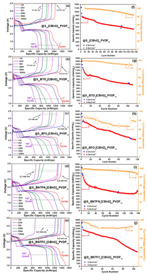
Figure 6.
Charge-discharge profiles and specific capacity, Coulombic efficiency in function cycle number spectra of battery with S25(CBhG)65PVDF10 at various current densities from 0.2 mA/cm2 to 0.3 mA/cm2 (a–f), battery with S25BTO5(CBhG)60PVDF10 (b–g), battery with S25BFO5(CBhG)60PVDF10 values (c–h), battery with S25BNTFN5(CBhG)60PVDF10 values (d–i), and battery with S25BNTFC5(CBhG)60PVDF10 values (e–j). All batteries were run over cycling at 0.2 mA/cm2 (first 3 cycles were run at 0.3 mA/cm2).
Table 4.
Comparison of specific capacity [mAh/gs] between 1st and 100th cycles, areal capacity for 1st cycle, and capacity retention for all batteries.
Figure 7a represents three plateau regions in the charge–discharge profiles, which are typical characteristics of Li-S batteries. The formation of a valley at the end of the first discharge plateau and a peak at the beginning of the charging process could be observed in the curves during the transition of ions from solid to liquid. In comparison to S25(CBhG)65PVDF10, S25BNTFC5(CBhG)60PVDF10 cathodes exhibited improved S utilization in terms of specific capacity (1123 mAh/gs versus 1509 mAh/gs), with mass loading (4.84 mgs/cm2 versus 6.74 mgs/cm2) and over potential (ΔE~0.16 V versus 0.17 V at the 2nd cycle), as shown in Figure 7a,b. Cycle performance testing (Figure 7b) was conducted to quantify the population of the battery, according to the requirements and life expectations of the battery for its various applications. With varying current densities, the discharge performance resulted in a two-way acceleration by means of increasing the battery degradation (capacity fade) rate and reducing the time required to complete one full charge-discharge cycle. Hence, it is very important to achieve a good cycling performance of the battery; it should thus be tested at various current densities for the accelerated use of Li-S batteries. To achieve high areal capacity, high mass loadings of 4.31 mgs/cm2, 3.625 mgs/cm2, 3.92 mgs/cm2, 3.45 mgs/cm2, and 4.46 mgs/cm2 were required. The highest initial discharge areal capacity reached > 6 mAh/cm2.
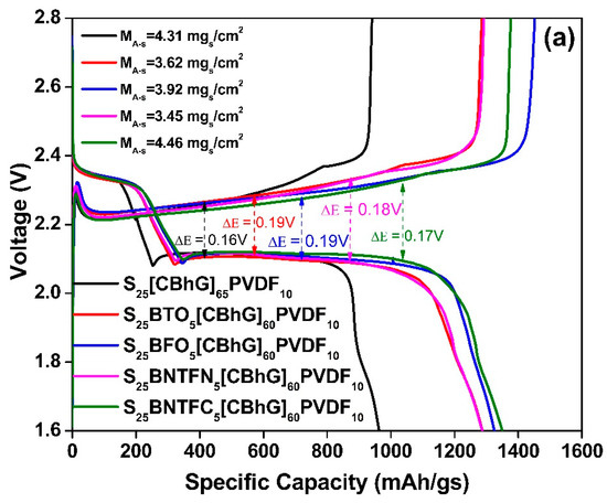
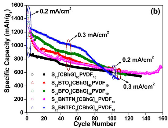
Figure 7.
Comparison of electrochemical performance of S25(CBhG)65PVDF10 and S25FNPs5(CBhG)60PVDF10 materials: (a) charge–discharge profile of 2 cycles for the batteries evaluated at current densities of 0.2 mA/cm2, (b) specific capacity in function cycle number at current densities of 0.2 mA/cm2 and 0.3 mA/cm2.
Figure 8 shows that the values of areal capacity reached 4.84 mAh/cm2, 5.08 mAh/cm2, 5.60 mAh/cm2, 5.12 mAh/cm2, and 6.74 mAh/cm2 for the S25(CBhG)65PVDF10, S25BTO5(CBhG)60PVDF10, S25BFO5(CBhG)60PVDF10, S25BNTFN5(CBhG)60PVDF10, and S25BNTFC5(CBhG)60PVDF10 cathode composites, respectively. Among the investigated composites, the highest areal capacity was obtained for the S25BNTFC5(CBhG)60PVDF10 cathode [49].
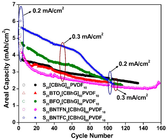
Figure 8.
Areal capacity for the batteries evaluated at different current densities ran at 0.2 mA/cm2 and 0.3 mA/cm2. The composite cathodes are represented by black circles for S25(CBhG)65PVDF10, red triangles for S25BTO5(CBhG)60PVDF10, green hexagons for S25BFO5(CBhG)60PVDF10, magenta circles for S25BNTFN5(CBhG)60PVDF10, and blue stars for S25BNTFC5(CBhG)60PVDF10.
4. Conclusions
In this work, sulfur composite cathodes were prepared, with hG as the dry pressable matrix and conductive scaffold. FNPs were added to improve electrochemical performance by reducing polysulfide shuttling. The Raman spectra confirmed the dominance of hG and the presence of FNPs in the composites, while SEM images confirmed the homogeneous distribution of FNPs throughout the composite matrix. EIS analysis confirmed the good diffusion of Li+ ions during charge–discharge of the composite electrodes. The enhancement in diffusion coefficients due to the coupling of FNPs was attributed to the improvement in the rate performance of the composites. The electrochemical performance represents an innovative contribution to the development of high energy density and stable Li-S batteries. The significant improvement in the stability as well as the dramatic change in the cyclability of the Li-S batteries was attributed to the contribution of the bi-functional effect of ferroelectricity coupled with the hG/S composite system. When BNTFN nanoparticles were incorporated into the cathode’s fabrication, the observed capacity at the first cycle was 1486 mAh/gs, and after ~158 cycles, it was still high (~676 mAh/gs). This also occurred with BNTFC, where the capacity started at ~1509 mAh/gs, and after 100 cycles, had a value of ~500 mAh/gs. The electrochemical performance retention of the fabricated electrodes up to 100 cycles showed a specific capacity (~541 mAh/gs). The Coulombic efficiency improved by more than 10% upon adding ferroelectric nanoparticles into the composite cathode. The highest areal capacity value obtained for the composite electrodes was 6.74 mAh/cm2. The incorporation of ferroelectric nanoparticles into the cathodes of Li-S batteries controlled the formation of polysulfides due to their internal electric fields, which reduced the rapid formation of polysulfides. This was attributed to the effect of an extra internal field induced by the ferroelectric nanoparticles. The development of such composite electrodes will provide good inspiration towards a strategy for suppressing the polysulfide shuttle phenomenon in the Li-S cell system and contribute to the advanced design of better Li-S cathodes for the next generation of energy storage systems.
Author Contributions
Conceptualization, C.C.Z.-G. and R.S.K.; methodology, C.C.Z.-G.; investigation, C.C.Z.-G., writing—original draft preparation, C.C.Z.-G.; writing—review and editing, B.T., R.K.K., C.O.P.-R.; M.C., R.S.K., D.K.P. and G.M.; supervision, M.C. and R.S.K.; funding acquisition, R.S.K. and G.M. All authors have read and agreed to the published version of the manuscript.
Funding
This research was funded by NASA MIRO PR-SPRInT, grant no. 80NSSC19M0236; NASA EPSCoR RID, grant no. 80NSSC19M0049; and NSF-EPSCoR Center for the Advancement of Wearable Technologies (CAWT) NSF, grant no. OIA-1849243.
Data Availability Statement
The data for this study are available from the corresponding authors upon request.
Acknowledgments
The authors are grateful for the financial support of NASA MIRO PR-SPRInT, grant no. 80NSSC19M0236; NASA EPSCoR, grant no. 80NSSC19M0049; and NSF-EPSCoR Center for the Advancement of Wearable Technologies (CAWT) NSF, grant no. OIA-1849243. We wish to express our gratitude to members of the SPECLAB group, especially William Pérez and the Molecular Science Research Center (MSRC) at the University of Puerto Rico, for the help and instruments provided during the experimental process and the fruitful discussions. We also thank Yi Lin from NASA Langley Research Center for providing the holey graphene material and for the fruitful discussions.
Conflicts of Interest
The authors declare no conflict of interest.
References
- Manthiram, A.; Chung, S.-H.; Zu, C. Lithium-Sulfur Batteries: Progress and Prospects. Adv. Mater. 2015, 27, 1980–2006. [Google Scholar] [CrossRef] [PubMed]
- Song, R.; Fang, R.; Wen, L.; Shi, Y.; Wang, S.; Li, F. A trilayer separator with dual function for high performance lithium–sulfur batteries. J. Power Sources 2016, 301, 179–186. [Google Scholar] [CrossRef]
- Bruce, P.G.; Freunberger, S.A.; Hardwick, L.J.; Tarascon, J.-M. Li-O2 and Li-S batteries with high energy storage. Nat. Mater. 2011, 11, 19–29. [Google Scholar] [CrossRef]
- Fang, R.; Zhao, S.; Sun, Z.; Wang, D.-W.; Cheng, H.-M.; Li, F. More Reliable Lithium-Sulfur Batteries: Status, Solutions and Prospects. Adv. Mater. 2017, 29, 1606823. [Google Scholar] [CrossRef] [PubMed]
- Lv, D.; Zheng, J.; Li, Q.; Xie, X.; Ferrara, S.; Nie, Z.; Mehdi, L.B.; Browning, N.D.; Zhang, J.-G.; Graff, G.L.; et al. High Energy Density Lithium-Sulfur Batteries: Challenges of Thick Sulfur Cathodes. Adv. Energy Mater. 2015, 5, 1402290. [Google Scholar] [CrossRef]
- Seh, Z.W.; Sun, Y.; Zhang, Q.; Cui, Y. Designing high-energy lithium-sulfur batteries. Chem. Soc. Rev. 2016, 45, 5605–5634. [Google Scholar] [CrossRef]
- Mikhaylik, Y.V.; Akridge, J.R. Polysulfide Shuttle Study in the Li-S Battery System. J. Ofthe Electrochem. Soc. 2004, 151, A1969–A1976. [Google Scholar] [CrossRef]
- Zhou, G.; Li, L.; Wang, D.-W.; Shan, X.-Y.; Pei, S.; Li, F.; Cheng, H.-M. A flexible sulfur-graphene-polypropylene separator integrated electrode for advanced Li-S batteries. Adv. Mater. 2015, 27, 641–647. [Google Scholar] [CrossRef]
- Liang, J.; Yin, L.; Tang, X.; Yang, H.; Yan, W.; Song, L.; Cheng, H.-M.; Li, F. Kinetically Enhanced Electrochemical Redox of Polysulfides on Polymeric Carbon Nitrides for Improved Lithium-Sulfur Batteries. ACS Appl. Mater. Interfaces 2016, 8, 25193–25201. [Google Scholar] [CrossRef]
- Han, X.; Yang, Z.; Zhao, B.; Zhu, S.; Zhou, L.; Dai, J.; Kim, J.-W.; Liu, B.; Connell, J.W.; Li, T.; et al. Compressible, Dense, Three-Dimensional Holey Graphene Monolithic Architecture. ACS Nano 2017, 11, 3189–3197. [Google Scholar] [CrossRef]
- Yen, Y.-J.; Chen, T.-H.; Wang, Y.-T.; Robles, A.; Đerić, M.; Miljanić, O.; Kaveevivitchai, W.; Chung, S.-H. Selective chemisorption of polysulfides by porous molecular crystal: Cathode host materials for lean-electrolyte lithium-sulfur cells with high electrochemical stability. J. Power Sources 2023, 565, 232891. [Google Scholar] [CrossRef]
- Shah, S.S.; Aziz, A.; Cevik, E.; Ali, M.; Gunday, S.T.; Bozkurt, A.; Yamani, Z.H. Sulfur nano-confinement in hierarchically porous jute derived activated carbon towards high-performance supercapacitor: Experimental and theoretical insights. J. Energy Storage 2022, 56, 105944. [Google Scholar] [CrossRef]
- Yan, S.-X.; Wang, Q.; Luo, S.-H.; Zhang, Y.-H.; Liu, X.; Liu, Y.-G.; Wang, Z.-Y.; Hao, A.-M.; Yi, T.-F. Coal-based S hybrid self-doped porous carbon for high-performance supercapacitors and potassium-ion batteries. J. Power Sources 2020, 461, 228151. [Google Scholar] [CrossRef]
- Zhang, M.; Song, Z.; Liu, H.; Wang, A.; Shao, S. MoO2 coated few layers of MoS2 and FeS2 nanoflower decorated S-doped graphene interoverlapped network for high-energy asymmetric supercapacitor. J. Colloid Interface Sci. 2021, 584, 418–428. [Google Scholar] [CrossRef] [PubMed]
- Raj, F.R.M.S.; Jaya, N.V.; Boopathi, G.; Kalpana, D.; Pandurangan, A. S-doped activated mesoporous carbon derived from the Borassus flabellifer flower as active electrodes for supercapacitors. Mater. Chem. Phys. 2020, 240, 122151. [Google Scholar]
- Gu, W.; Sevilla, M.; Magasinski, A.; Fuertes, A.B.; Yushin, G. Sulfur-containing activated carbons with greatly reduced content of bottle neck pores for double-layer capacitors: A case study for pseudocapacitance detection. Energy Environ. Sci. 2013, 6, 2465–2476. [Google Scholar] [CrossRef]
- Cao, S.; Liu, D.; Ding, H.; Lu, H.; Gui, J. Towards understanding corrosion inhibition of sulfonate/carboxylate functionalized ionic liquids: An experimental and theoretical study. J. Colloid Interface Sci. 2020, 579, 315–329. [Google Scholar] [CrossRef]
- Sahoo, R.K.; Singh, S.; Yun, J.M.; Kwon, S.H.; Kim, K.H. Sb2S3 Nanoparticles Anchored or Encapsulated by the Sulfur-Doped Carbon Sheet for High-Performance Supercapacitors. ACS Appl. Mater. Interfaces 2019, 11, 33966–33977. [Google Scholar] [CrossRef]
- Wang, C.; Zhang, S.-H.; Zhang, L.; Xi, R.; Jiang, D.-P.; Chen, Z.-Y.; Huang, H.; Ding, L.-Y.; Pan, G.-B. Natural bamboo leaves derived sulphur-doped mesoporous heteroatom enriched carbon for high-performance supercapacitors and gas sensors. J. Power Sources 2019, 443, 227183. [Google Scholar] [CrossRef]
- Zhou, Y.; Candelaria, S.L.; Liu, Q.; Huang, Y.; Uchaker, E.; CaO, G. Sulfur-rich carbon cryogels for supercapacitors with improved conductivity and wettability. J. Mater. Chem. A 2014, 2, 8472–8482. [Google Scholar] [CrossRef]
- Ma, X.; Song, X.; Ning, G.; Hou, L.; Kan, Y.; Xiao, Z.; Li, W.; Ma, G.; Gao, J.; Li, Y. S-Doped Porous Graphene Microspheres with Individual Robust Red-Blood-Cell-Like Microarchitecture for Capacitive Energy Storage. Ind. Eng. Chem. Res. 2017, 56, 9524–9532. [Google Scholar] [CrossRef]
- Salhabi, E.H.M.; Zhao, J.; Wang, J.; Yang, M.; Wang, B.; Wang, D. Hollow Multi-Shelled Structural TiO2-x with Multiple Spatial Confinement for Long-Life Lithium-Sulfur Batteries. Angew. Chem. Int. Ed. Engl. 2019, 58, 9078–9082. [Google Scholar] [CrossRef] [PubMed]
- Song, J.; Yu, Z.; Gordin, M.L.; Wang, D. Advanced Sulfur Cathode Enabled by Highly Crumpled Nitrogen-Doped Graphene Sheets for High-Energy-Density Lithium-Sulfur Batteries. Nano Lett. 2016, 16, 864–870. [Google Scholar] [CrossRef] [PubMed]
- Noheda, B.; Kooi, B.J. Ferroelectric chalcogenides—Materials at the edge. Science 2016, 353, 221–222. [Google Scholar]
- Zhou, W.; Guo, B.; Gao, H.; Goodenough, J.B. Low-Cost Higher Loading of a Sulfur Cathode. Adv. Energy Mater. 2016, 6, 1502059. [Google Scholar] [CrossRef]
- Ji, X.; Lee, K.T.; Nazar, L.F. A highly ordered nanostructured carbon-sulphur cathode for lithium-sulphur batteries. Nat. Mater. 2009, 8, 500–506. [Google Scholar] [CrossRef]
- Xiao, J.; Wang, H.; Li, X.; Wang, Z.; Ma, J.; Zhao, H. N-doped carbon nanotubes as cathode material in Li–S batteries. J. Mater. Sci. Mater. Electron. 2015, 26, 7895–7900. [Google Scholar] [CrossRef]
- Liu, T.; Zhang, L.; Cheng, B.; Hu, X.; Yu, J. Holey Graphene for Electrochemical Energy Storage. Cell Rep. Phys. Sci. 2020, 1, 100215. [Google Scholar] [CrossRef]
- Yim, T.; Han, S.H.; Park, N.H.; Park, M.-S.; Lee, J.H.; Shin, J.; Choi, J.W.; Jung, Y.; Jo, Y.N.; Yu, J.-S.; et al. Effective Polysulfide Rejection by Dipole-Aligned BaTiO3 Coated Separator in Lithium-Sulfur Batteries. Adv. Funct. Mater. 2016, 26, 7817–7823. [Google Scholar] [CrossRef]
- Cheng, H.; Liu, H.; Jin, H.; Cai, N.; Gao, C.; Zhao, S.; Wang, M. Suppression of polysulfide shuttling with a separator modified using spontaneously polarized bismuth ferrite for high performance lithium–sulfur batteries. J. Mater. Chem. A 2020, 8, 16429–16436. [Google Scholar] [CrossRef]
- Xie, K.; You, Y.; Yuan, K.; Lu, W.; Zhang, K.; Xu, F.; Ye, M.; Ke, S.; Shen, C.; Zeng, X.; et al. Ferroelectric-Enhanced Polysulfide Trapping for Lithium-Sulfur Battery Improvement. Adv. Mater. 2016, 29, 1604724. [Google Scholar] [CrossRef] [PubMed]
- Zhao, Z.; Li, G.; Wang, Z.; Feng, M.; Sun, M.; Xue, X.; Liu, R.; Jia, H.; Wang, Z.; Zhang, W.; et al. Black BaTiO3 as Multifunctional Sulfur Immobilizer for Superior Lithium Sulfur Batteries. J. Power Sources 2019, 434, 226729. [Google Scholar] [CrossRef]
- Tripathi, B.; Katiyar, R.K.; Morell, G.; Dixit, A.; Katiyar, R.S. BiFeO3 Coupled Polysulfide Trapping in C/S Composite Cathode Material for Li-S Batteries as Large Efficiency and High Rate Performance. Energies 2021, 14, 8362. [Google Scholar] [CrossRef]
- Półrolniczak, P.; Walkowiak, M.; Kaźmierczak-Raźna, J.; Kasprzak, D.; Mathew, D.E.; Kathiresan, M.; Stephan, A.M.; Angulakshmi, N. BaTiO3-g-GO as an efficient permselective material for lithium–sulfur batteries. Mater. Chem. Front. 2021, 5, 950–960. [Google Scholar] [CrossRef]
- Zuluaga-Gómez, C.C.; Plaza-Rivera, C.O.; Tripathi, B.; Katiyar, R.K.; Pradhan, D.K.; Morell, G.; Lin, Y.; Correa, M.; Katiyar, R.S. Holey Graphene/Ferroelectric/Sulfur Composite Cathodes for HighCapacity Lithium–Sulfur Batteries. ACS OMEGA 2023, 8, 13097–13108. [Google Scholar] [CrossRef]
- Lin, Y.; Han, X.; Campbell, C.J.; Kim, J.-W.; Zhao, B.; Luo, W.; Dai, J.; Hu, L.; Connell, J.W. Holey Graphene Nanomanufacturing: Structure, Composition, and Electrochemical Properties. Adv. Funct. Mater. 2015, 25, 2920–2927. [Google Scholar] [CrossRef]
- Zhao, X.; Liu, W.; Chen, W.; Li, S. Preparation and properties of BaTiO3 ceramics from the fine ceramic powder. Ceram. Int. 2015, 41, S111–S116. [Google Scholar] [CrossRef]
- Bernardo, M.; Jardiel, T.; Peiteado, M.; Caballero, A.; Villegas, M. Reaction pathways in the solid state synthesis of multiferroic BiFeO3. J. Eur. Ceram. Soc. 2011, 31, 3047–3053. [Google Scholar] [CrossRef]
- Lin, Y.; Jones, K.J.; Greenburg, L.C.; Kim, J.-W.; Hu, L.; Connell, J.W. Facile, Solvent-Free Preparation of High Density, High Mass Loading Sulfur Cathodes Enabled by Dry-Pressable Holey Graphene Scaffolds. Batter. Supercaps 2019, 2, 774–783. [Google Scholar] [CrossRef]
- Das, S.R.; Choudhary, R.N.P.; Bhattacharya, P.; Katiyar, R.S.; Dutta, P.; Manivannan, A.; Seehra, M.S. Structural and Multiferroic Properties of La-Modified BiFeO3 Ceramics. J. Appl. Phys. 2007, 101, 034104. [Google Scholar] [CrossRef]
- Chen, X.; Xiao, J.; Yao, J.; Kang, Z.; Yang, F.; Zeng, X. Room Temperature Magnetoelectric Coupling Study in Multiferroic Bi4NdTi3Fe0.7Ni0.3O15 Prepared by a Multicalcination Procedure. Ceram. Int. 2014, 40, 6815–6819. [Google Scholar] [CrossRef]
- Yang, F.J.; Su, P.; Wei, C.; Chen, X.Q.; Yang, C.P.; Cao, W.Q. Large Magnetic Response in (Bi4Nd)Ti3(Fe0.5Co0.5)O15 Ceramic at Room-Temperature. J. Appl. Phys. 2011, 110, 126102. [Google Scholar] [CrossRef]
- Radhika, G.; Subadevi, R.; Krishnaveni, K.; Liu, W.R.; Sivakumar, M. Synthesis and Electrochemical Performance of PEG-MnO(2)-Sulfur Composites Cathode Materials for Lithium-Sulfur Batteries. J. Nanosci. Nanotechnol. 2018, 18, 127–131. [Google Scholar] [CrossRef] [PubMed]
- Li, M.; Zhang, Y.; Bai, Z.; Liu, W.W.; Liu, T.; Gim, J.; Jiang, G.; Yuan, Y.; Luo, D.; Feng, K.; et al. A Lithium-Sulfur Battery using a 2D Current Collector Architecture with a Large-Sized Sulfur Host Operated under High Areal Loading and Low E/S Ratio. Adv. Mater. 2018, 30, e1804271. [Google Scholar] [CrossRef]
- Nguyen, T.Q.; Breitkopf, C. Determination of Diffusion Coefficients Using Impedance Spectroscopy Data. J. Electrochem. Soc. 2018, 165, E826–E831. [Google Scholar] [CrossRef]
- Wang, T.; Zhang, Q.; Zhong, J.; Chen, M.; Deng, H.; Cao, J.; Wang, L.; Peng, L.; Zhu, J.; Lu, B. 3D Holey Graphene/Polyacrylonitrile Sulfur Composite Architecture for High Loading Lithium Sulfur Batteries. Adv. Energy Mater. 2021, 11, 2100448. [Google Scholar] [CrossRef]
- Gaberscek, M. Understanding Li-based battery materials via electrochemical impedance spectroscopy. Nat. Commun. 2021, 12, 6513. [Google Scholar] [CrossRef] [PubMed]
- Rana, M.; Ahad, S.A.; Li, M.; Luo, B.; Wang, L.; Gentle, I.; Knibbe, R. Review on areal capacities and long-term cycling performances of lithium sulfur battery at high sulfur loading. Energy Storage Mater. 2019, 18, 289–310. [Google Scholar] [CrossRef]
- Fan, C.-Y.; Yuan, H.-Y.; Li, H.-H.; Wang, H.-F.; Li, W.-L.; Sun, H.-Z.; Wu, X.-L.; Zhang, J.-P. The Effective Design of a Polysulfide-Trapped Separator at the Molecular Level for High Energy Density Li-S Batteries. ACS Appl Mater Interfaces 2016, 8, 16108–16115. [Google Scholar] [CrossRef] [PubMed]
Disclaimer/Publisher’s Note: The statements, opinions and data contained in all publications are solely those of the individual author(s) and contributor(s) and not of MDPI and/or the editor(s). MDPI and/or the editor(s) disclaim responsibility for any injury to people or property resulting from any ideas, methods, instructions or products referred to in the content. |
© 2023 by the authors. Licensee MDPI, Basel, Switzerland. This article is an open access article distributed under the terms and conditions of the Creative Commons Attribution (CC BY) license (https://creativecommons.org/licenses/by/4.0/).