Article

Enhancing Performance of LiFePO4 Battery by Using a Novel Gel Composite Polymer Electrolyte

Institute of Materials Science & Devices, School of Material Science and Engineering, Suzhou University of Science and Technology, Suzhou 215000, China
*
Author to whom correspondence should be addressed.
Batteries 2023, 9(1), 51; https://doi.org/10.3390/batteries9010051
Submission received: 12 November 2022 / Revised: 31 December 2022 / Accepted: 10 January 2023 / Published: 11 January 2023
(This article belongs to the Special Issue Emerging Technologies for Secondary Batteries)

Abstract

:
Composite polymer electrolyte (CPE) is expected to have great prospects in solid-state batteries. However, their application is impeded due to the poor interfacial compatibility between CPE and electrodes that result in sluggish ionic transformation, especially at low temperatures. Here, on the basis of Poly (vinylidene fluoride-co-hexafluoropropylene) (PVDF-HFP) polymer electrolyte, gel composite polymer electrolyte (GCPE) with fast Li+ transport channel is prepared by in-situ polymerization with poly (ethylene glycol) methyl ether acrylate (PEGMEA) monomer and FEC as additive. Compared with CPE, GCPE increases the ionic conductivity by 10 times. It also achieves more uniform lithium precipitation and significantly inhibits the growth of lithium dendrites. The LFP/GCPE/Li battery has a capacity retention of over 99% at both room temperature and 0 °C after 100 cycles. In addition, the coulombic efficiency is above 99% during cycling. Our work provides a new technology to prepare GCPE with high ionic conductivity at both room temperature and low temperatures that has great potential in the application of solid-state lithium batteries.

1. Introduction

Rechargeable batteries play an important role in electric vehicles, electronic equipment and grid energy storage devices. Lithium metal batteries (LMBs) have attracted great attention due to its high energy density [1,2,3,4,5]. In the last decade, solid-state lithium batteries have developed rapidly [6,7,8]. Among many solid electrolytes, polymer materials have been widely used, such as poly (ethylene oxide) (PEO) [9] and poly(vinylidenefluoride) (PVDF) [10]. Unfortunately, the low ionic conductivity and mechanical strength of polymer electrolyte (PE) (10−6–10−9 S cm−1) seriously restricts its commercial application. In recent years, ionic and proton liquids [11] are often used in combination with polymer electrolytes. Adding inorganic ceramic materials as fillers to prepare composite electrolytes is an effective method to improve ionic conductivity and mechanical strength of PE [12,13,14]. Nevertheless, the latest research shows that composite polymer electrolytes (CPE) still have some interface problems [15]. The poor interfacial contact between electrolyte and electrode will bring large impedance and affect the cycling performance. This situation is more serious at low temperatures [16].
An ideal solid-state lithium battery should ensure that the electrolyte layer has high mechanical strength, high ionic conductivity, and excellent interface contact, so as to restrain the growth of lithium dendrites and give full play to the advantageous performance [17,18,19,20]. Although researches have reported excellent ionic conductivity for CPEs, the CEPs often need to soak liquid electrolyte to achieve better interfacial contact, which will cause some potential safety hazards. Moreover, these studies rarely involve the operation of batteries at low temperatures. Yang Li et al. reported a composite polymer electrolyte (CPE) based on garnet Li7La3Zr2O12 (LLZO) nanofiber-incorporated Poly (vinylidene fluoride co hexafluoropropylene) (PVDF-HFP) which has a great ionic conductivity of 9.5 × 10⁻⁴ S cm−1 at room temperature [21]. However, some liquid electrolytes still need to be added in some electrochemical tests. Guo et al. prepared the polymerized composite electrolytes (PCEs) by in-situ polymerization which has an ionic conductivity of 1.18 × 10⁻⁴ S cm−1 at 30 ℃ and electrochemically stable up to 6.5 V versus Li/Li+ at room temperature [22]. Unfortunately, no characterization and test below 0 °C was carried out. Xu et al. invented a PEO based solid state lithium battery that can operate at 0 °C [23]. The LiFePO4/Li cell delivers a specific capacity of 118.6 m Ah g−1 at 0.1C and a capacity retention of 82% after 180 cycles. The performance and capacity retention of solid-state lithium battery at low temperature can also be improved.
In this work, a novel gel composite polymer electrolyte (GCPE) was prepared by in-situ polymerization. The formed GCPE with fast Li+ transport channels allow an ionic conductivity of 1.19 × 10⁻⁴ S cm−1 at room temperature and 2.51 × 10⁻⁵ S cm−2 at 0 °C. The Li/GCPE/Li Stable cycle more than 700 h. Benefiting from the excellent ion transport performance and good interfacial contact of GCPE, the fabricated LiFePO4/GCPE/Li battery achieves a high specific capacity of 164.7 m Ah g−1 at 0.1C and obtains a capacity retention of 99% after 100 cycles. Even at 0 °C, the battery shows a high discharge capacity of 127 mA g−1 at 0.1C and its capacity retention rate is also above 99% afer 100 cycles. Our work provides a new and feasible idea for improving the performance of quasi solid-state lithium batteries at low temperatures.

2. Materials and Methods

2.1. Materials

Li7La3Zr2O12 (LLZO) (HF-kejing, Hefei, China), bis (trifluoromethanesulfoneimide) lithium salt (LiTFSI) (99.99%, Macklin, Shanghai, China), azodiisobutyronitrile;azobisisobutyronitrile (AIBN) (Mw = 156.21, Macklin, Shanghai, China), polyvinylidenefluoride-co-hexafluoropropylene (PVDF-HFP) (Mw = 400,000, Sigma-Aldrich, St. Louis, MO, USA), poly (ethylene glycol) methyl ether acrylate (PEGMEA) (Mw = 480, Sigma-Aldrich, St. Louis, MO, USA), 4-Fluoro-1,3-dioxolan-2-one (FEC) (Macklin, Shanghai, China),dimethylformamide (DMF) (99.9%, Sigma-Aldrich, St. Louis, MO, USA).

2.2. Preparation of Composite Polymer Electrolyte (CPE)

The CPE were prepared by a solution casting method. The thickness of CPE was be kept between 49 μm and 62.5 μm. To form a uniform CPE film, 250 mg PVDF-HFP, 125 mg LiTFSI and 41.7 mg LLZO were dissolved in 10 mL DMF and stirred at room temperature for 12 h to obtain a uniform solution. Pour the mixed slurry onto the horizontal Teflon plate, and dry it under vacuum at 70 °C for 12 h to remove most of the DMF solvent. Store the dried CPE film in the glove box filled with argon.

2.3. Preparation of Gel Composite Polymer Electrolyte (GCPE)

Dissolve 1 mol/L LiTFSI, 10 wt% LLZO and 1 wt% AIBN in the polymer monomer PEGMEA at room temperature, then add 20 wt% FEC and stir at 1000 rpm for 5 h to obtain the precursor. Then, drop the uniformly mixed precursor onto the CPE film and heat at 100 °C for 120 s to induce complete polymerization of polymer monomer [15]. Finally, a gel-like conformant polymer electrolyte (GCPE) was obtained. All the above operations were carried out in the glove box filled with argon (≤0.1 ppm H2O and O2).

2.4. Preparation of Cathodes

80 wt% LFP, 10 wt% Super-P and 10 wt% PVDF (polyvinylidene fluoride) were mixed together with N-methyl pyrrolidinone (NMP) to obtain the slurry with uniform mixing. Use a doctor blade to evenly spread the paste on the aluminum foil and dry it at 80 °C for 12 h. Cut these foils into round cathode with a diameter of 12 mm. The active substance loading of each cathode is 1.75 mg/cm−2.

2.5. Cell Assembly and Measurements

In this work, 2032-type coin cells were used for testing in all environments. The assembly process of LFP/CPE/Li is as follows: place the lithium metal anode in the negative electrode shell and place CPE on it, then complete the battery assembly with the cathode and stainless-steel spring. LFP/GCPE/Li is prepared by in-situ polymerization. First, place the lithium metal anode in the cathode shell, followed by CPE, and drop 10 μL mixed monomer precursor slurry, finally place it in the cathode and complete the in-situ polymerization at 100 °C. The multi-channel battery tester used for electrochemical testing is Landt Battery Test Systems. The charge/discharge voltage range was 2.5–4.0 V for LFP cathodes and the 1C rate is determined to be 170 m Ah g−1.

2.6. Characterization

The structure of lithium metal anode and solid electrolyte was examined by scanning electron microscopy (SEM) (JEOL-7100F, Takashima, Tokyo). Use the same SEM to observe the cross-section of CPE/Li and GCPE/Li morphologies and to obtain the energy dispersive spectral (EDS) mapping images. The thermogravimetric analysis (TGA) of the sample is conducted at a heating rate of 5 °C/min under nitrogen environment with Perkin Elmer UNIX/TGA7. X-ray diffraction (XRD) (D8 DISCOVER, Bruker, Karlsruhe, Germany) was used for phase identification with Cu Kα radiation (1.5418 Å) in a 2θ range of 10° to 70°. X-ray photoelectron spectroscopy (XPS) (JPS-9200, JEOL, Takashima, Tokyo) was used to analyze the deep etching of lithium anode with Etch Time of 20 and Etch Level of 20.
The electrochemical test is completed on the electrochemical workstation (Princeton Applied Research AMETEK). Clamp CPE and GCPE with stainless steel sheets on both sides (SS/CPE/SS, SS/GCPE/SS) for electrochemical impedance spectroscopy (EIS) test with a frequency range from 0.1 Hz to 1 M Hz and an amplitude of 10 mV. All cells used in EIS tests were pressed under a pressure of 500 psi. The calculation formula of ionic conductivity σ is as follows:
σ = d S × R b
where d (cm) is the thickness of solid electrolyte, S (cm−2) is the effective contact area of solid electrolyte, R b (Ω) is the volume resistance in EIS of solid electrolyte. The activation energy is calculated as follows:
σ = A e x p ( E a K T )
where σ (S cm−1) is the ionic conductivity, A   is the pre-exponential factor, E a   (kJ/mol) is the activation energy for lithium-ion conduction, K is the Boltzmann constant, and T (K) is the measure temperature. In order to test the electrochemical stability of solid electrolyte, the electrochemical window of CPE/GCPE at room temperature was measured by linear scanning voltammetry (LSV). Use SS as the working electrode and a lithium metal as the counter electrode at a scan rate of 0.5 mV s−1 from 0 to 6 V.

3. Results and Discussion

The interface contact improvement of solid-state lithium battery by in-situ polymerization is shown in Figure 1a. Unlike the direct use of CPE, we uniformly disperse LiTFSI and LLZO in the liquid monomer and cast the mixed monomer into the self-supported CPE skeleton, and then in situ polymerize to prepare homogenous oxide/polymer composite at 100 °C. In this case, precursor fillers can construct continuous Li+ conducting pathway along both the oxide phase [24] and the resultant oxide/polymer interfacial layer for fast Li+ conduction, at the same time, good contact between electrolyte and electrode also benefits from in situ polymerization.
As shown in Figure 1b, PEGMEA, as a monomer, solidifies from liquid to gel-like quasi-solid polymer, indicating that in situ polymerization occurs on the electrolyte. Meanwhile, GCPE prepared by in situ polymerization has good mechanical flexibility, and the thickness does not increase significantly compared with CPE. In Figure 1c, the thickness of CPE is 52 µm and the thickness of GCPE is 55 µm, which is much thinner than PEO-based solid-state electrolyte [25].
It has been proved that in situ polymerization is an effective method to reduce the surface impedance [26]. In this work, the contact between GCPE and electrode is greatly improved by in situ polymerization technology. In order to ensure the consistency of the two membranes before participating in the test, Li/GCPE/Li and Li/CPE/Li coin cells were fabricated, in which Li/GCPE/Li coin cells were prepared by in-situ polymerization. Two kinds of coin cells were stand still for 2 h, then cycled for 1 h at a current density of 0.5 mA cm−2, and disassembled and tested for cross section SEM and EDS. From the cross-sectional SEM image of GCPE/Li (Figure 2a), it can be seen that the GCPE and the lithium metal anode are fully bonded to obtain good interfacial compatibility. The distribution of elements C, S, F and La at the cross section is given through the EDS images (Figure 2b–e). It can clearly be observed that GCPE is located at the surface of lithium metal. Moreover, C, S, F and La elements are distributed uniformly on the surface of the film. However, CPE (Figure S1) is not well stickered together with Li metal. There are conventional and in-situ gaps between CPE and lithium metal. The ratios of different elements were obtained by surface scanning of CPE/Li and GCPE/Li (Table S1 in Supplementary Materials). When the proportion of LLZO is 10%, the proportion of La and P detected by GCPE/Li is significantly higher than that of CPE. This showed that the content of LLZO in GCPE is higher and the distribution is more uniform, indicating that LLZO and LiTFSI are more fully involved in the fast transmission of Li+ in GCPE.
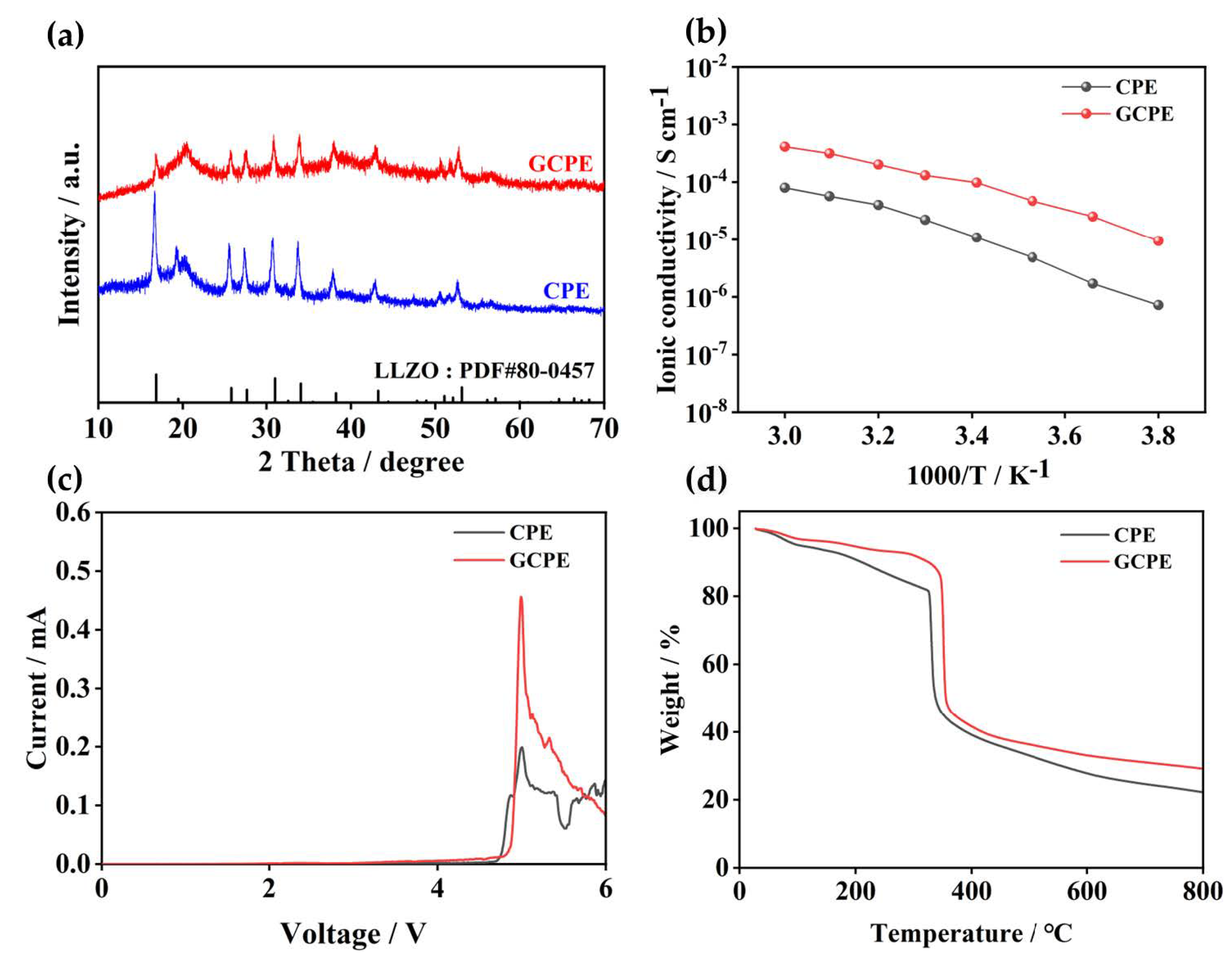
Figure 3a displays XRD patterns of GCPE and CPE. the diffraction peaks at around 18, 20, 26 and 40 are ascribed to the crystalline structure of pure PVDF-HFP [20]. The XRD patterns also show that LLZO has been embedded in GCPE and CPE. More importantly, the diffraction peak intensity of GCPE prepared by in situ polymerization is significantly lower than that of CPE, which proves that the crystallinity of GCPE is significantly lower than that of CPE. The decrease of crystallinity is mainly attributed to the casting of homogeneous monomers during the preparation of GCPE which made LLZO more evenly distributed in the whole electrolyte. In a previous report, He et al. used the method of adding active fillers with high ionic conductivity to the polymer to achieve lower crystallinity [27]. This work filled more LLZO in the preparation of GCPE to reduce the crystallinity of polymer materials. This treatment will make it easier for LLZO to promote the interaction between polymer chains and ionic species, thus affecting the recrystallization of PVDF-HFP and leading to more amorphous regions. Electrochemical impedance spectroscopy (EIS) of SS/GCPE/SS and SS/CPE/SS (SS: stainless steel) symmetrical cells were evaluated from −10 °C to 60 °C (Figure S3a,b). SS/CPE/SS directly uses the dried CPE film for assembly test, SS/GCPE/SS needs to be prepared by in-situ polymerization. The ionic conductivity is calculated by the resistance (Rb) obtained from EIS [28,29]. As shown, the ionic conductivity of GCPE can be up to 1.19 × 10⁻⁴ mS cm−1 while the ionic conductivity of CPE is only 1.64 × 10⁻⁵ mS cm−1 at 25 °C. At the same time, it can be seen from Figure S4a that as the electrolyte changes from CPE to GCPE, the activation energy also decreases from 0.31 eV to 0.23 eV. Moreover, GCPE still retains high ionic conductivity of 2.51 × 10⁻⁵ mS cm−1 much larger than 1.7 × 10⁻⁶ mS cm−1 of CPE at 0 °C. It can be observed that the ionic conductivity of GCPE is much higher than that of CPE, especially at below 0 °C. The ionic conductivity of GCPE is also at a moderate level among many polymer electrolytes of the same type. The much superior ionic conductivity of GCPE can be attributed to the more uniform dispersion of LLZO and LiTFSI in GCPE, that helps to form a high-speed Li+ transmission channel [30]. Meanwhile, this also shows that low crystallinity plays a beneficial role in ion transport [31]. To obtain a stable electrochemical window for GCPE and CPE, we did a linear scanning volume velocimetry (LSV) measurement (Figure 3c). It shows that oxidation stability (vs. Li/Li+) for GCPE is 4.6 V, which is higher than that of CPE (4.5 V). Thermogravimetric analysis (TGA) analysis is conducted to study the thermal stability of CPE and GCPE membranes (Figure 3d). As shown, the thermal stability of GCPE is better than that of CPE which can attributed to that GCPE has been heated at 100 °C and its crystallinity has decreased during the preparation process. Moreover, PEGMEA and FEC are additionally used compared with CPE, which may also contribute to the improvement of thermal stability for GCPE [32].
To analyze the interface contact and stability between CPE/GCPE and lithium metal anode, Li/GCPE/Li cells and Li/CPE/Li cells were assembled and tested at a current density of 0.2 mA cm−2 (Figure 4a). As can be observed, the Li/GCPE/Li cell still exhibit no short circuit after 700 h, indicating the reversible lithium electroplating/stripping based on GCPE, and stable interface between electrolyte and lithium anode. In addition, Li/GCPE/Li symmetric cell maintains low voltage polarization during cycles. As shown in Figure S5a, at a relative current density of 0.2 mA cm−2, the overpotential of Li/GCPE/Li increase to 76 mV, 131 mV and 187 mV after 2 h, 300 h,700 h of cycling. At a current density of 0.5 mA cm−2, the Li/GCPE/Li symmetric cell has no short circuit after 150 h of cycles. In contrast, Li/CPE/Li had a soft short circuit after only 30 h of cycling at 0.2 mA cm−2 and the polarization potential has reached 255 mV in the first hour of the cycle [33]. When the current density is increased to 0.5 mA cm−2, Li/CPE/Li cell is short circuited after working for 3 h. It can be seen from Figure 4b and Table S3 that the Rct of Li/CPE/Li symmetric cells after 700 h of cycles is 79 Ω larger than that before cycles, while for Li/GCPE/Li symmetric cell, the Rct increased by 6 Ω, almost unchanged. The insufficient adhesion between CPE and lithium anode leads to obvious gap between CPE and Li. These gaps make it impossible to restrain the growth of lithium dendrites [34,35,36]. In a long-term cycle, it will lead to an increase in irreversibility of lithium electroplating/stripping. It can be observed from the SEM image in Figure 4d that lithium dendrites grow obviously on lithium metal after 700 h of cycling in Li/CPE/Li battery. The excessive growth of lithium dendrites may puncture the electrolyte membrane, and this is the reason why the Li/CPE/Li symmetrical cells had a soft short circuit very early. These lithium dendrites remain on the surface of CPE after cycling and are concentrated in some areas and have been agglomerated into irregular small pieces (Figure S6b). In contrast, although a small amount of LLZO agglomerates on the freshly prepared GCPE surface, (Figure S6d), no obvious lithium dendrites were found on the surface of lithium metal (Figure 4e) after 700 h of operation. Furthermore, legacy of GCPE can be observed from SEM images. This shows that in situ polymerization makes GCPE/Li fully compatible.
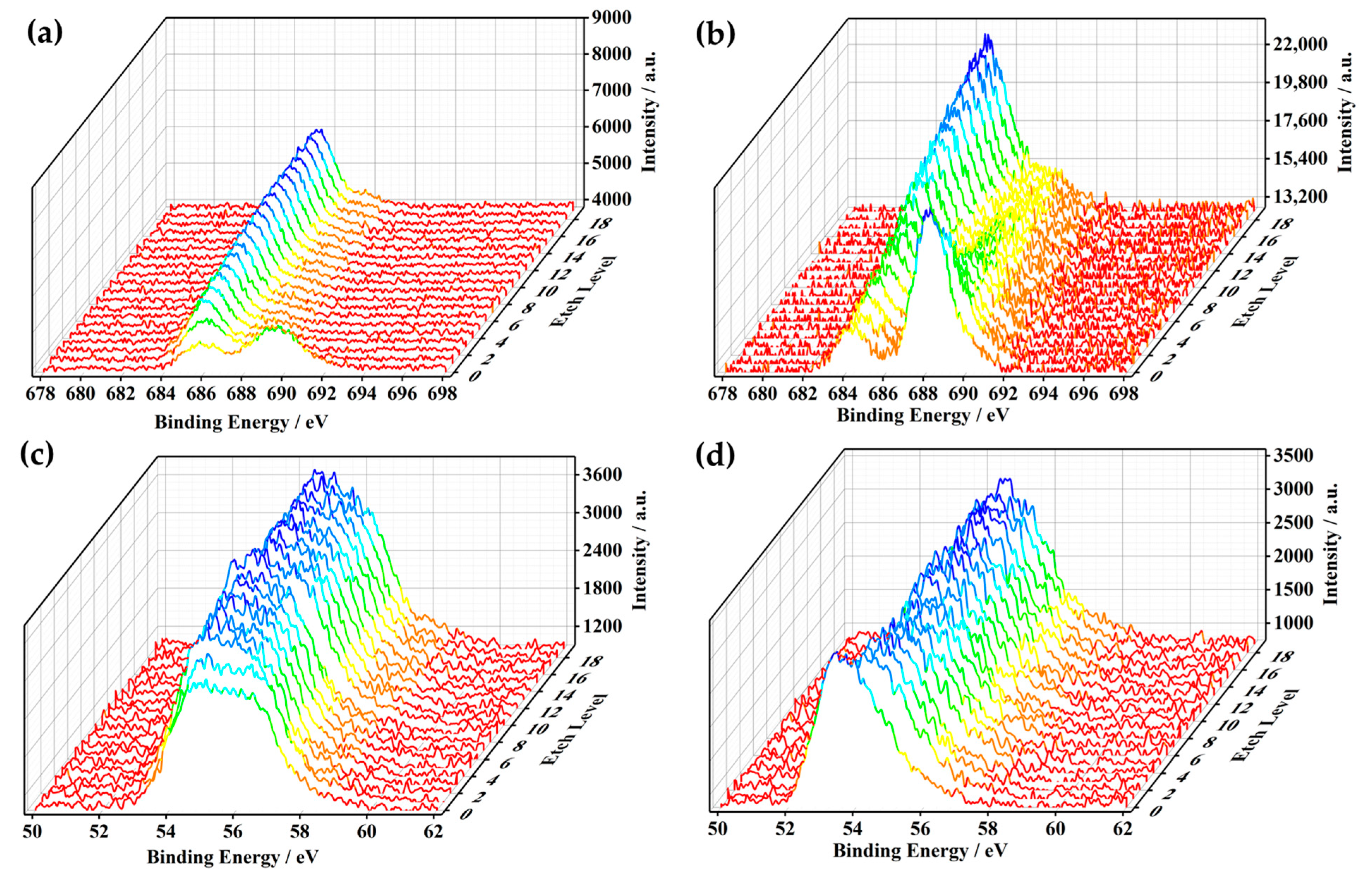
In order to analyze the influence of interface compatibility on lithium metal more comprehensively, lithium metal in the symmetrical battery after 700 h cycling was analyzed by X-ray photoelectron spectroscopy (XPS). All curves were calibrated with C1s 284.8 eV. The prepared sample is placed in a vacuum bottle until it is transferred to the XPS equipment for testing. We etched the lithium metal for 20 times and each time for 20 s to analysis Li and F distribution on lithium metal surface. Figure 5a,b are XPS of F1s on the surface of lithium metal from Li/CPE/Li and Li/GCPE/Li, respectively. Without Ar+ etching, 685.7 eV and 688.9 eV signals in the F1s spectrogram correspond to Li–F and C–F bonds, respectively. With the deepening of the etching, the signal at 688.9 eV disappears rapidly and the signal at 685.7 eV becomes slightly stronger and tends to be stable. The existence of the C–F signal can be attributed to polymer (PVDF-HFP) and LiTFSI in solid electrolyte. Due to the poor interfacial contact, there are only a few CPE residues on the lithium metal surface, leading to the rapid disappearance of the C–F signal along etching. Furthermore, the poor interface compatibility of CPE and Li which allows a small amount of LiTFSI in the electrolyte decomposes on the surface of lithium metal, leading to stable Li–F signals. In situ polymerization process makes the adhesion of GCPE/Li closer, resulting in the existence of GCPE residue with uniform thickness on the surface of lithium metal. As shown in Figure 5b, the signal of 688.9 eV gradually weakens with the deepening of etching. The C-F gradually weakens with the increase of etching, which confirms the uniform residue of GCPE on the lithium metal surface. The signal of 685.7 eV gradually increases with the deepening of etching, and the relative strength of the signal is far greater than that detected on CPE/Li. This is due to the uniform protective layer formed by FEC in GCPE on the surface of lithium metal. With the deepening of etching, the protective layer is gradually detected, leading to the Li–F signal gradually enhanced. As shown in Figure 5c, the 54.9 eV signal for Li1s increases rapidly with the deepening of etching and tends to be stable, reflecting the increasing amount of Li. Since there is only a small amount of CPE residue on the surface of lithium metal, and there are a large number of cavities generated by the growth of lithium dendrites on the interface of CPE/Li, the signal at 54.9 eV increases rapidly at the beginning of etching. The signal at 55.3 eV corresponds to Li–CO3, which is derived from the residue of LiTFSI in CPE on the surface of lithium metal. As shown in Figure 5d, Li1s of Lithium metal from Li/GCPE/Li did not fluctuate greatly, indicating that the excellent interface compatibility of GCPE/Li, which will have a crucial influence on the stability of lithium metal long-term cycle [37].
A series of electrochemical tests were conducted to evaluate the electrochemical performance of GCPE. At room temperature, LFP/GCPE/Li cells have a specific discharge capacity of 164.7 m Ah g−1 at 0.1C. After 100 cycles, the capacity retention is over 99% and the Coulomb efficiency is also higher than 99% during cycling. However, the specific discharge capacity of LFP/CPE/Li cells at room temperature is very poor and the coulomb efficiency fluctuates greatly. This is due to the low ionic conductivity of CPE on the one hand, and the poor interface contact between CPE and electrode on the other hand, resulting in excessive interface resistance. As shown in Figure S7a, LFP/CPE/Li has relatively large interface impedance (Rct = 2264 Ω) before cycling. At 0 °C, LFP/GCPE/Li cells have a specific discharge capacity of 128.4 m Ah g−1 at 0.1C and the capacity retention rate is higher than 99% with coulomb efficiency over 99% after 100 cycles. Low ionic conductivity of CPE at low temperature makes LFP/CPE/Li cells unable to work at 0 °C and the adverse effect of interface impedance on cell performance is more obvious at low temperature. LFP/GCPE/Li cells have excellent capacity retention rates both at room temperature and at 0 °C (Figure 6b,e), which fully shows that good contact between electrolyte and electrode has a very important impact on cell performance. The excellent performance of GCPE at 0 °C is also attributed to the FEC added in the preparation process which can form an extremely uniform SEI between electrolyte and electrode to improve the interface impedance and cell performance at low temperature [38,39,40,41]. The LFP/GCPE/Li cell achieved a discharge capacity of 164.7, 158.6, 132.1, 94.1 and 58.3 mAh g−1 at 0.1C, 0.2C, 0.5C. 1C and 2C respectively (Figure 6e) at 0 °C. LFP/CPE/Li has almost lost its charging and discharging capacity at 0.2C because of excessive interface impedance has more serious adverse effects on cell cycles under higher current density.
In order to study the evaluation process of the interface impedance of two different cells, we assembled LFP/GCPE/Li cells and LFP/CPE/Li cells to observe their impedance in the static state. Initial Rct of LFP/CPE/Li is up to 2264 Ω. Furthermore, a Rsei = 685 Ω has been tested, which is almost undetectable in Li/GCPE/Li (Figure S2a). After 14 days of standstill, the impedance change of Li/CPE/Li is not obvious. The initial Rct of Li/GCPE/Li is 301 Ω and after 7, 14, 21 days of inactivity, the Rct is changed to 380 Ω, 469 Ω and 473 Ω, respectively. After 14 days of standing, the impedance of Li/GCPE/Li will not increase significantly and no obvious Rsei is detected. This reflects that GCPE will not be excessively aged after a long time of standing, so as to ensure the provision of high-speed Li+ transport channel for a long time. The EIS of these two electrolytes is so different, mainly due to the following two reasons: on the one hand, LFP/GCPE/Li is prepared by in situ polymeri–tion to determine the contact between GCPE, and the electrode is excellent. On the other hand, the SEI formed by FEC is so thin that it is not enough to form Rsei and will not produce for interface compatibility [42]. Poor interface contacts between CPE and metal Li results in unstable interface conditions.

4. Conclusions

In this work, we adopted a simple and effective method to improve the low temperature performance of quasi solid electrolyte. A fast ion transport channel was constructed by in situ polymerization and a gel-like quasi solid electrolyte (GCPE) was formed. It improves the poor compatibility between the traditional PVDF-HFP based composite polymer electrolyte and electrodes, in addition, it not only effectively reduces the interface impedance, but also further inhibits the growth of lithium dendrite. Cells made with GCPE have high capacity retention and performance at room temperature and low temperature. This design opens up a new way to prepare solid materials which can be used at room temperature and low temperature.

Supplementary Materials

The following supporting information can be downloaded at: https://www.mdpi.com/article/10.3390/batteries9010051/s1, Figure S1: Cross section SEM of CPE/Li and EDS mapping of C, S, F, La for CPE/Li; Figure S2: SEM of demarcated area for CPE/Li and GCPE/L; Figure S3: EIS of SS/CPE/SS and SS/GCPE/SS at different evaluated temperatures; Figure S4: The temperature depend–ency of ionic conductivity of CPE and GCPE; Figure S5: Ymmetric-cell cycling of Li/CPE/Li (red line) and Li/GCPE/Li (black line). The current density was fixed at 0.5 mA cm−2 during the tests; Figure S6: SEM of CPE and GCPE before and after cycling for 700 h; Figure S7: The EIS of LFP/CPE/Li battery for different aging time; Figure S8: Cycle perfor–mance of LFP/Pes/Li at at room temperature and 0 ℃; Table S1: Element content of selected area for Figure S2a (CPE/Li); Table S2: Element content of selected area for Figure S2b (CPE/Li); Table S3: Changes of resistance values of each part before and after Li/CPE/Li and Li/GCPE/Li cycles for Figure 4b.

Author Contributions

K.W. conceptualized the experiments and analyzed the data. K.W., N.H., S.W., Z.G. and W.D. discussed the results, as well as wrote and revised the document. All authors have read and agreed to the published version of the manuscript.

Funding

The authors gratefully acknowledge the support from National Natural Science Foundation of China (No. 21905194).

Data Availability Statement

Not applicable.

Conflicts of Interest

The authors declare no conflict of interest.

References

  1. Goodenough, J.B.; Kim, Y. Challenges for rechargeable Li batteries. Chem. Mater. 2010, 22, 587–603. [Google Scholar] [CrossRef]
  2. Dunn, B.; Kamath, H.; Tarascon, J.M. Electrical energy storage for the grid: A battery of choices. Science 2011, 334, 928–935. [Google Scholar] [CrossRef] [PubMed] [Green Version]
  3. Goodenough, J.B.; Park, K.S. The Li-ion rechargeable battery: A perspective. J. Am. Chem. Soc. 2013, 135, 1167–1176. [Google Scholar] [CrossRef]
  4. Wu, H.; Cui, Y. Designing nanostructured Si anodes for high energy lithium ion batteries. Nano Today 2012, 7, 414–429. [Google Scholar] [CrossRef]
  5. Xu, W.; Wang, J.; Ding, F.; Chen, X.; Nasybulin, E.; Zhang, Y.; Zhang, J.G. Lithium metal anodes for rechargeable batteries. Energy Environ. Sci. 2014, 7, 513–537. [Google Scholar] [CrossRef]
  6. Armand, M.; Tarascon, J.M. Building better batteries. Nature 2008, 451, 652–657. [Google Scholar] [CrossRef]
  7. Chen, R.; Li, Q.; Yu, X.; Chen, L.; Li, H. Approaching practically accessible solid-state batteries: Stability issues related to solid electrolytes and interfaces. Chem. Rev. 2019, 120, 6820–6877. [Google Scholar] [CrossRef]
  8. Liu, G.; Sun, Q.; Li, Q.; Zhang, J.; Ming, J. Electrolyte issues in lithium–sulfur batteries: Development, prospect, and challenges. Energy Fuels 2021, 35, 10405–10427. [Google Scholar] [CrossRef]
  9. Wang, C.; Zhang, X.W.; Appleby, A.J. Solvent-free composite PEO-ceramic fiber/mat electrolytes for lithium secondary cells. J. Electrochem. Soc. 2004, 152, A205. [Google Scholar] [CrossRef]
  10. Yu, J.; Kwok, S.C.; Lu, Z.; Effat, M.B.; Lyu, Y.Q.; Yuen, M.M.; Ciucci, F. A ceramic-PVDF composite membrane with modified interfaces as an ion-conducting electrolyte for solid-state lithium-ion batteries operating at room temperature. ChemElectroChem 2018, 5, 2873–2881. [Google Scholar] [CrossRef]
  11. Kachmar, A.; Carignano, M.; Laino, T.; Iannuzzi, M.; Hutter, J. Mapping the free energy of lithium solvation in the Protic ionic liquid ethylammonuim nitrate: A metadynamics study. ChemSusChem 2017, 10, 3083–3090. [Google Scholar] [CrossRef] [PubMed] [Green Version]
  12. Prasanth, R.; Aravindan, V.; Srinivasan, M. Novel polymer electrolyte based on cob-web electrospun multi component polymer blend of polyacrylonitrile/poly (methyl methacrylate)/polystyrene for lithium ion batteries—Preparation and electrochemical characterization. J. Power Sources 2012, 202, 299–307. [Google Scholar] [CrossRef]
  13. Liang, B.; Tang, S.; Jiang, Q.; Chen, C.; Chen, X.; Li, S.; Yan, X. Preparation and characterization of PEO-PMMA polymer composite electrolytes doped with nano-Al2O3. Electrochim. Acta 2015, 169, 334–341. [Google Scholar] [CrossRef]
  14. Lu, Y.; Tu, Z.; Archer, L.A. Stable lithium electrodeposition in liquid and nanoporous solid electrolytes. Nat. Mater. 2014, 13, 961–969. [Google Scholar] [CrossRef] [Green Version]
  15. Song, S.; Qin, X.; Ruan, Y.; Li, W.; Xu, Y.; Zhang, D.; Thokchom, J. Enhanced performance of solid-state lithium-air batteries with continuous 3D garnet network added composite polymer electrolyte. J. Power Sources 2020, 461, 228146. [Google Scholar] [CrossRef]
  16. Han, X.; Gong, Y.; Fu, K.K.; He, X.; Hitz, G.T.; Dai, J.; Hu, L. Negating interfacial impedance in garnet-based solid-state Li metal batteries. Nat. Mater. 2017, 16, 572–579. [Google Scholar] [CrossRef]
  17. Wang, M.; Wu, Y.; Qiu, M.; Li, X.; Li, C.; Li, R.; Chen, Y. Research progress in electrospinning engineering for all-solid-state electrolytes of lithium metal batteries. J. Energy Chem. 2021, 61, 253–268. [Google Scholar] [CrossRef]
  18. Heubner, C.; Liebmann, T.; Voigt, K.; Weiser, M.; Matthey, B.; Junker, N.; Michaelis, A. Scalable fabrication of nanostructured tin oxide anodes for high-energy lithium-ion batteries. ACS Appl. Mater. Interfaces 2018, 10, 27019–27029. [Google Scholar] [CrossRef]
  19. Li, W.; Song, B.; Manthiram, A. High-voltage positive electrode materials for lithium-ion batteries. Chem. Soc. Rev. 2017, 46, 3006–3059. [Google Scholar] [CrossRef]
  20. Tan, S.J.; Yue, J.; Tian, Y.F.; Ma, Q.; Wan, J.; Xiao, Y.; Guo, Y.G. In-situ encapsulating flame-retardant phosphate into robust polymer matrix for safe and stable quasi-solid-state lithium metal batteries. Energy Storage Mater. 2021, 39, 186–193. [Google Scholar] [CrossRef]
  21. Li, Y.; Zhang, W.; Dou, Q.; Wong, K.W.; Ng, K.M. Li7La3Zr2O12 ceramic nanofiber-incorporated composite polymer electrolytes for lithium metal batteries. J. Mater. Chem. A 2019, 7, 3391–3398. [Google Scholar] [CrossRef]
  22. Li, Z.; Xie, H.X.; Zhang, X.Y.; Guo, X. In situ thermally polymerized solid composite electrolytes with a broad electrochemical window for all-solid-state lithium metal batteries. J. Mater. Chem. A 2020, 8, 3892–3900. [Google Scholar] [CrossRef]
  23. Xu, S.; Sun, Z.; Sun, C.; Li, F.; Chen, K.; Zhang, Z.; Li, F. Homogeneous and fast ion conduction of PEO-based solid-state electrolyte at low temperature. Adv. Funct. Mater. 2020, 30, 2007172. [Google Scholar] [CrossRef]
  24. Yang, T.; Zheng, J.; Cheng, Q.; Hu, Y.Y.; Chan, C.K. Composite polymer electrolytes with Li7La3Zr2O12 garnet-type nanowires as ceramic fillers: Mechanism of conductivity enhancement and role of doping and morphology. ACS Appl. Mater. Interfaces 2017, 9, 21773–21780. [Google Scholar] [CrossRef]
  25. Hanai, K.; Ueno, M.; Imanishi, N.; Hirano, A.; Yamamoto, O.; Takeda, Y. Interfacial resistance of the LiFePO4-C/PEO-LiTFSI composite electrode for dry-polymer lithium-ion batteries. J. Power Sources 2011, 196, 6756–6761. [Google Scholar] [CrossRef]
  26. Xu, K. Nonaqueous liquid electrolytes for lithium-based rechargeable batteries. Chem. Rev. 2004, 104, 4303–4418. [Google Scholar] [CrossRef]
  27. He, K.; Chen, C.; Fan, R.; Liu, C.; Liao, C.; Xu, Y.; Li, R.K. Polyethylene oxide/garnet-type Li6. 4La3Zr1. 4Nb0. 6O12 composite electrolytes with improved electrochemical performance for solid state lithium rechargeable batteries. Compos. Sci. Technol. 2019, 175, 28–34. [Google Scholar] [CrossRef]
  28. Jia, X.; Zhang, C.; Wang, L.; Zhang, W.; Zhang, L. Modification of Cycle Life Model for Normal Aging Trajectory Prediction of Lithium-Ion Batteries at Different Temperatures and Discharge Current Rates. World Electr. Veh. J. 2022, 13, 59. [Google Scholar] [CrossRef]
  29. Doux, J.M.; Yang, Y.; Tan, D.H.; Nguyen, H.; Wu, E.A.; Wang, X.; Meng, Y.S. Pressure effects on sulfide electrolytes for all solid-state batteries. J. Mater. Chem. A 2020, 8, 5049–5055. [Google Scholar] [CrossRef]
  30. Woods, J.; Bhattarai, N.; Chapagain, P.; Yang, Y.; Neupane, S. In situ transmission electron microscopy observations of rechargeable lithium ion batteries. Nano Energy 2019, 56, 619–640. [Google Scholar] [CrossRef]
  31. Wang, S.; Zhang, W.; Chen, X.; Das, D.; Ruess, R.; Gautam, A.; Janek, J. Influence of crystallinity of lithium thiophosphate solid electrolytes on the performance of solid-state batteries. Adv. Energy Mater. 2021, 11, 2100654. [Google Scholar] [CrossRef]
  32. Sun, Q.; Chen, X.; Xie, J.; Shen, C.; Jin, Y.; Huang, C.; Cheng, J. Scale-up processing of a safe quasi-solid-state lithium battery by cathode-supported solid electrolyte coating. Mater. Today Energy 2021, 21, 100841. [Google Scholar] [CrossRef]
  33. Huang, L.; Liu, L.; Lu, L.; Feng, X.; Han, X.; Li, W.; Ouyang, M. A review of the internal short circuit mechanism in lithium-ion batteries: Inducement, detection and prevention. Int. J. Energy Res. 2021, 45, 15797–15831. [Google Scholar] [CrossRef]
  34. Mu, W.; Liu, X.; Wen, Z.; Liu, L. Numerical simulation of the factors affecting the growth of lithium dendrites. J. Energy Storage 2019, 26, 100921. [Google Scholar] [CrossRef]
  35. Lin, D.; Liu, Y.; Liang, Z.; Lee, H.W.; Sun, J.; Wang, H.; Cui, Y. Layered reduced graphene oxide with nanoscale interlayer gaps as a stable host for lithium metal anodes. Nat. Nanotechnol. 2016, 11, 626–632. [Google Scholar] [CrossRef]
  36. Love, C.T.; Baturina, O.A.; Swider-Lyons, K.E. Observation of lithium dendrites at ambient temperature and below. ECS Electrochem. Lett. 2015, 4, A24. [Google Scholar] [CrossRef]
  37. Liu, T.; Zhang, J.; Han, W.; Zhang, J.; Ding, G.; Dong, S.; Cui, G. In situ polymerization for integration and interfacial protection towards solid state lithium batteries. J. Electrochem. Soc. 2020, 167, 070527. [Google Scholar] [CrossRef]
  38. Yu, X.; Wang, L.; Ma, J.; Sun, X.; Zhou, X.; Cui, G. Selectively wetted rigid–flexible coupling polymer electrolyte enabling superior stability and compatibility of high-voltage lithium metal batteries. Adv. Energy Mater. 2020, 10, 1903939. [Google Scholar] [CrossRef]
  39. Zhang, X.; Ren, Y.; Zhang, J.; Wu, X.; Yi, C.; Zhang, L.; Qi, S. Synergistic Effect of TMSPi and FEC in Regulating the Electrode/Electrolyte Interfaces in Nickel-Rich Lithium Metal Batteries. ACS Appl. Mater. Interfaces 2022, 14, 11517–11527. [Google Scholar] [CrossRef]
  40. Hu, L.; Zhang, Z.; Amine, K. Fluorinated electrolytes for Li-ion battery: An FEC-based electrolyte for high voltage LiNi0.5Mn1.5O4/graphite couple. Electrochem. Commun. 2013, 35, 76–79. [Google Scholar] [CrossRef]
  41. Li, Q.; Liu, G.; Cheng, H.; Sun, Q.; Zhang, J.; Ming, J. Low-Temperature Electrolyte Design for Lithium-Ion Batteries: Prospect and Challenges. Chem. Eur. J. 2021, 27, 15842–15865. [Google Scholar] [CrossRef] [PubMed]
  42. Veith, G.M.; Doucet, M.; Sacci, R.L.; Vacaliuc, B.; Baldwin, J.K.; Browning, J.F. Determination of the solid electrolyte interphase structure grown on a silicon electrode using a fluoroethylene carbonate additive. Sci. Rep. 2017, 7, 1–15. [Google Scholar] [CrossRef] [PubMed]
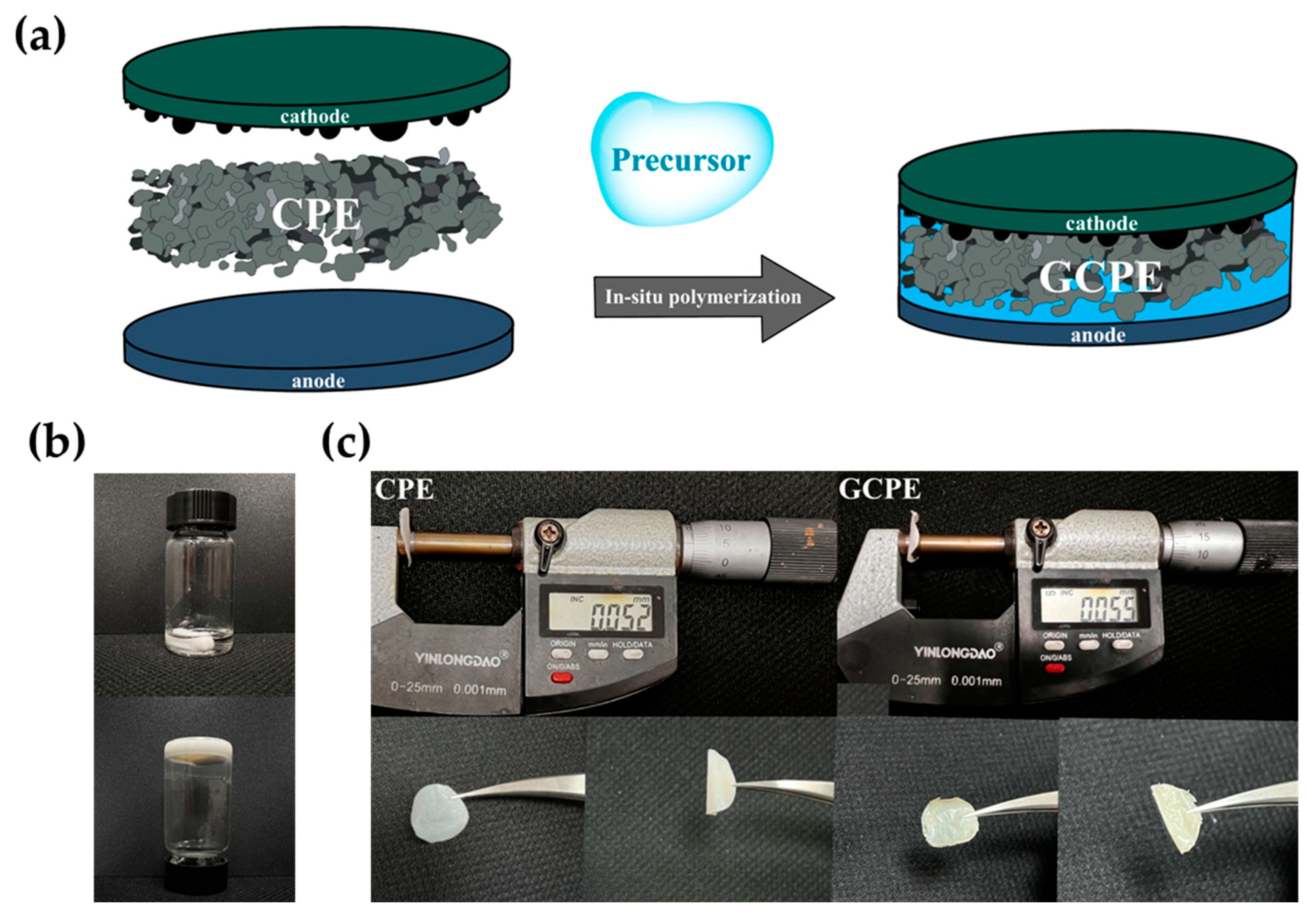
Figure 1. (a) Schematic diagram of in–situ polymerization work. (b) An optical picture describing the solidification of a material from a liquid state to a gel state. (c) Appearance and thickness mea–urement diagram of CPE and GCPE.
Batteries 09 00051 g001
Figure 2. (a) Cross section SEM of GCPE/Li. (be), EDS mapping of C, S, F, La for GCPE/Li.
Batteries 09 00051 g002
Figure 3. (ad) The XRD, Arrhenius, LSV, TGA of CPE and GCPE.
Batteries 09 00051 g003
Figure 4. (a) Li/CPE/Li symmetric cells and Li/GCPE/Li symmetric cells were tested at 0.2 mA/cm−2 for 700 h. (b) EIS of Li/CPE/Li and Li/GCPE/Li. (ce) SEM of fresh lithium metal and metallic lithium in Li/CPE/Li and metallic lithium in Li/GCPE/Li after 700 h.
Batteries 09 00051 g004
Figure 5. (a,b) XPS patterns (F1s) of lithium metal from Li/CPE/Li and Li/GCPE/Li after 700 h cycle. (c,d) XPS patterns (Li1s) of lithium metal from Li/CPE/Li and Li/GCPE/Li after 700 h cycle.
Batteries 09 00051 g005
Figure 6. (a) Cycling performance of LFP/CPE/Li cells and LFP/GCPE/Li cells at room temperature. (b) Charge/discharge profiles of LFP/GCPE/Li at room temperature. (c) Rate capability of LFP/GCPE/Li at room temperature. (d) Cycling performance of LFP/GCPE/Li at 0 °C. (e) Charge/di−charge profiles of LFP/GCPE/Li at 0 °C. (f) The EIS of LFP/GCPE/Li battery for different aging time.
Batteries 09 00051 g006
Disclaimer/Publisher’s Note: The statements, opinions and data contained in all publications are solely those of the individual author(s) and contributor(s) and not of MDPI and/or the editor(s). MDPI and/or the editor(s) disclaim responsibility for any injury to people or property resulting from any ideas, methods, instructions or products referred to in the content.