1. Introduction
With the increasing proportion of new energy power generation, its intermittency and volatility cause difficulties in power accommodation and grid connection. Fortunately, the introduction of all kinds energy storage devices greatly alleviates this dilemma by increasing reserve capacity, cutting peak and filling valley and restraining power fluctuation [
1]. Energy storage technology breaks the traditional mode of power generation and consumption and becomes an important supporting technology for building smart grids [
2].
For a battery energy storage system (BESS), the State-of-Charge (SoC) is a key parameter. Due to the complexity of battery structure and electrochemical reaction, SoC is often difficult to obtain directly. For SoC estimation in a BMS, common methods mainly include look-up table [
3], ampere-hour integral (AHI) method [
4], filter-based method, observer-based method, data-driven-based method [
5], etc. Among them, the AHI method is popular for its simplicity and ease of controller design. Additionally, in all control objectives of SoC in BMS, balance is the most basic and important one.
The ways to realize SoC balance mainly include active method and passive method [
6,
7,
8]. The authors in [
7,
8] compare the advantages and disadvantages of SoC active equalization and passive equalization through simulation, and they point out that the active equalization method is more energy-saving and generates less heat. Therefore, the active equalization method has aroused great interest, which is usually in centralized or decentralized manners [
6,
7,
8,
9,
10,
11]. For example, in [
9], the SoC balance strategy for cascaded-type energy storage systems is put forward in a decentralized way. A hierarchical method in the decentralized manner is proposed in [
10] to balance SoC at both the cell level and the module level. However, a centralized balance controller is easy to lead to single-point failure and is hard to extend, while a decentralized balance controller limits the design of the system controller with the absence of communication among cells [
12]. In view of this, a lot of researchers have focused on designing the distributed SoC balance controllers.
Among the distributed methods, the research results based on multiagent systems (MASs) are quite rich, which directly balance SoC both in charging and discharging mode. The direct balancing method refers to that each battery directly uses its own and neighbor’s SoC to build a distributed controller. Among them, there are both single-integrator- [
13,
14,
15,
16,
17,
18] and double-integrator-based MASs [
19,
20] that manage SoCs. Most controller designs are based on asymptotically stable control [
13,
19], finite time [
15,
21,
22] and fixed-time [
23,
24,
25] stable control, event-triggered control [
22,
26,
27] and fault-tolerant control [
14,
15,
16,
17,
20,
27] and attempt to solve the problems with communication delay [
13,
14,
18] and input delay, switching topology [
13,
14,
18], etc. All of these are average consensus designs, without exception. These designs focus on solving or optimizing the convergence rate of direct balance, energy conservation and communication efficiency, time delay problems, sensor failures, network failures and attacks. It is worthy to mention that the objectives of double-integrator systems are power sharing and SoC balance. It seems that the authors who designed these excellent controllers did not consider the reasonable arrangement of current to fully charge them in charging mode.
Recently, some new control objectives have emerged and some researchers have captured these and carried out research. In [
28], the mutual restraining heat balance and SoC balance are well solved based on MAS consensus methods. SoC estimators for neighbored batteries are designed both in [
29,
30]. The difference is that the controller designed by authors in [
29] realizes the precision adjustable sharing of dynamic power and SoC balancing when the battery is empty or full, while in [
30], based on the reference current signal obtained by the modelless iPI controller, the battery is guided to charge and discharge. Similar designs as in [
30] also appear in [
31]. Additionally, the topic on the economic dispatch of SoC has also attracted the attention of scholars. As analyzed in [
32,
33], the cost function of battery power generation is a quadratic function about SoC, and if the increment cost of each battery reaches consensus, the generation cost is the minimum. These new ideas give a lot of inspiration. However, the leaderless charging strategy still focuses on realizing the direct balance of SoC and does not suppress the imbalance of SoC during the charging process and the accurate balance at the time of full charge through reasonable current arrangement.
In the distributed new energy power generation systems, BESS is often used to suppress the uncertainty and intermittency of new energy power generation. In addition, BESS, as the emergency standby power supply, needs to deal with various emergencies. In view of the needs of these application backgrounds, it is necessary to restrain SoC imbalance by arranging charging current reasonably at all times. However, the traditional three-stage charging method only pays attention to the filling of the single battery and does not pay attention to the SoC balance between the battery units during the charging process. As a result, the battery unit is in a state of large SoC imbalance during mode switching. In the previous literature, a leaderless consensus control input is designed which focuses on active SoC balance but ignores the boundedness of SoC. Although some literature has obtained the reference current of DC chopper through some methods, they are either decentralized or do not consider the suppression of SoC imbalance.
To provide an advanced distributed charging scheme for a battery, we introduce the smart leader–follower model [
34,
35,
36,
37] to obtain the desired reference current for each DC chopper in this paper. Under the traditional leader–follower framework, the stability of the system depends too much on the leader’s state. Additionally, excessive deviation between the leader and its neighbored followers is harmful to the dynamic performance of the system. The smart leader adopts the follower’s feedback in a timely way to modify its control law, so as to reduce the tracking error, which is conducive to improving the stability of the system. The detailed contributions are as follows:
The smart leader method is applied here. In this paper, a distributed charging scheme based on MASs with a smart leader is designed for battery charging. A constant leader is modified by a dynamic leader by using the reference and the follower’s state when appropriate. According to [
32], this transformation makes the leader smart enough to reduce the deviation between all followers and the leader. Under this control framework, SoC imbalance can be suppressed.
The smart leadership is achieved by event-triggering strategy [
34]. If the error exceeds the predefined threshold, the smart leader adopts it to amend the control input; otherwise, the reference is only used. The two kinds of error between the leader and its neighbors are used here, i.e., the maximum error (ME) and weighted error (WE). From the simulation results, the smart leader based on ME has advantages over the one based on WE in suppressing SoC imbalance in the later stage.
The system with input time delay is transformed to a nondelay system. Based on the Artstein reduction method, the system with input time delay is reduced to the nondelay system, and there is no need to give input time delay a limit. From the simulation point of view, such a larger input time-delayed system matched by a smaller gain is more conducive to stability.
The rest of the sections are arranged as follows.
Section 2 introduces SoC estimation by the current integration method, active and passive SoC balance methods, the smart leader and graph theory.
Section 3 presents two novel distributed charging strategies based on a smart leader and gives their input time-delayed control inputs. Some cases are designed in
Section 4 to verify the proposed control strategies.
Notations: is an n-dimensional column vector whose elements are all 1, and is a zero matrix of proper dimension. denotes a matrix of . represents the diagonal matrix with vector v as the main diagonal.
2. Preliminaries
A typical multi-BESS network is shown in
Figure 1, where the inverter is the main component for bridging the DC part and the AC part. A double closed-loop control (DCLC) is usually implemented to drive the inverter. In the DC part, the charge and discharge of the battery are controlled by a PWM-driven bidirectional DC chopper, which is responsible for providing adjustable voltage. The control loop of the bidirectional DC chopper contains a MAS-based distributed controller for charge and discharge current control and provides reference current for it.
2.1. The Estimation of SoC and Its Balance Strategy
For a power system with
n BESSs, the energy level of a battery is usually characterized by SoC. Additionally, the SoC of battery
is estimated as (1) in charging mode
where
is the output current of battery
i, and
is called the capacity of battery
i, which represents the heterogeneity of a battery. This is the so-called AHI method [
5] and a formula about the dimension of time as hours. Find the derivative of (1) as
For simplicity, the time variables are omitted in the subsequent narrations. Thus, the charging system of battery is subjected to
where
is replaced by
.
When it comes to SoC balance strategy, active and passive methods are two mainstream balancing technologies [
5,
8]. The passive balance strategy requires designing a discharge circuit, which is conducive to additionally consume high levels of SoC to reach the lowest level. This method causes the unnecessary power consumption and the heat production in this process. The active balance strategy is aimed at arranging the output current of each battery to realize the balance. Unlike the former, SoC is reallocated by arranging reasonable current among battery units under the active method. This design of SoC balance strategy for BESS will help to make full use of the capacity of each cell, so as to maximize the load capacity of the power system. Thus, the active method becomes the most promising balance technology. In view of this, the objective of this paper is to obtain a reference current in order to suppress the imbalance of SoC during charging.
2.2. Consensus Design for MASs with a Smart Leader
Based on MASs, direct active SoC balance is essentially the redistribution of SoC in the form of charging and discharging between BESS, which will generate large power circulation between some two BESSs in parallel, whether in charge mode or discharge mode. This is because the difference between the SoC of each cell is too large, and power exchange may occur between some cells. In case of emergency, BESS needs to be put into use at any time. The excessive SoC deviation makes the BESS obtain a large and long-lasting circulation during the balanced operation, which is not conducive to maintain a high power factor of the system but also causes excessive losses in the line. Thus, the charging strategy for a multi-BESS network needs to be redesigned to ensure SoC balance as much as possible.
In the classical leader–follower model shown in
Figure 2a, the leader agent generally chooses the dictatorship strategy, in which the states of each follower are not concerned by the leader. This obviously does not constrain the deviation between the SoC of each battery in the charging mode.
In view of this, we introduce the smart leader method to transform the classic leader by adding a discontinuous communication item. Specifically, the smart leader has the right to decide to use follower information to modify their control law at an appropriate time. Nevertheless, a virtual constant leader is applied in the traditional distributed charging strategy. It is necessary to define a leader agent to produce a new reference signal for its neighbored followers, as shown in
Figure 2b. Additionally, this leader agent is smart enough to know when to modify its dynamic by the information of its adjacent agents.
Compared with the strategy with the virtual constant leader, the smart leadership pays more attention to the real-time dynamics of followers. When the SoC imbalance exceeds the given threshold, the smart leader can adjust its own state to guide its neighbors to adjust their own control laws to promote SoC balance.
2.3. Graph Theory
Consider a BESS containing n batteries, in which each one is governed by an agent. Define a set , any element of which represents an agent. The measured SoC of each battery is uploaded to its own agent. Then, an agent has the ability to access others’ data over a communication graph , where is a set of channels and denotes that there exists a channel from agent j to i, and agent j is called the neighbor of agent i. Denote as the set of neighbors of agent i. For the MASs governing BESS, define an adjacency matrix , where if ; otherwise, . Define that the Laplacian matrix , where and .
For the leader–follower model, define a vector and if follower i can access the leader; otherwise, . Assume that at least one follower can access the leader.
Lemma 1 ([
37]).
Denote , and and are the maximum and minimum eigenvalue of H, respectively, and H is positive definite. 3. Various Distributed Charging Strategies Based on MASs with the Smart Leader
For multiple BESSs in parallel, charging balance strategy is required so that batteries with SoC at different levels are fully charged simultaneously, i.e., time-oriented consistency. Based on the classical leader–follower model, the distributed charging control law is defined as
where
is the consensus gain, and
is a virtual leader. Since
, it is reasonable to set
equal to 1.
Next, briefly analyze the stability of the system (3) under the controller (4).
Define the error vector
between the SoCs and the desired state
. Find the derivatives of
and bring (3) and (4) into it. Then, one can obtain
Thus, according to Lemma 1,
is negative definite, and the system (5) is asymptotically stable.
The distributed charging strategy (4) is effective only if . However, SoC imbalance in the charging process is not effectively inhibited under this strategy, which leads to the hidden danger of some large circulations among BESSs when switching to the discharge mode. To alleviate this problem, we give two novel charging strategies with the smart leader in this paper, where one is based on ME and the other is based on WE.
To facilitate subsequent analysis, some useful existing conclusions in Lemmas 2 and 3 are given below without proof.
Lemma 2 ([
38]).
For a switched system , σ belongs to the finite set ; if the origin is a globally asymptoptotically stable equilibrium for all subsystems, then this switched system is globally uniformly asymptotically stable. Lemma 3 ([
39,
40]).
(Artstein’s transformation) A system with input time-delay is represented byDefine . Thus, this system can be reduced asif, for the initial existance of the system, the initial state value over interval is specified, and u is integrable. 3.1. Distributed Charging Control with Smart Leader Based on ME
Here, the constant leader is reformed, and a virtual pinned dynamic leader agent is defined. Referring to [
35], the control input of the new dynamic leader is
where
represents the smart leadership, and
C is a row vector. As required in [
33], only one neighbored agent of the leader is directly involved in (6). Thus,
. Define
and a threshold
. Then,
and
, which means that the neighbor who has the biggest error from the leader will be used to participate in regulating the leader’s state if SoC imbalance exceeds the threshold. If not, only the desired SoC
is used to adjust the leader.
Then, the control input for battery
i pinned by the modified leader state
is
With the aforementioned lemmas in hand, we give the following theorem and its proof.
Theorem 1. Assume that there is a power system containing n BESSs, and each battery is governed by an agent, whose SoC is subjected to (3), and the equipped communication network satisfies that at least one follower agent is connected to the smart leader. Then, if and , the SoC of each battery can converge to asymptotically under the smart leadership (6).
Proof. Define the error vector between the follower agents and the smart leader
and the error vector between the smart leader agent and the desired value
. With support of (2), (6) and (7), find the derivatives of
and
as follows
where
is the control gain. Thus, (8a) and (8b) can be rewritten as
where
,
,
and
.
The characteristic polynomial of the matrix is , which gives zero eigenvalues and one nonzero eigenvalue . Thus, the system is Bounded-Input–Bounded-Output (BIBO) stable if . In fact, is negative definite by mathematical induction. That is to say that the system (9) with is asymptotically stable. Thus, according to Lemma 2, the system (9) is globally uniformly asymptotically stable under the smart leadership (6). In other words, the SoC of each battery and can asymptotically converge to and , respectively. □
3.2. Distributed Charging Control with the Smart Leader Based on WE
In this section, we give another smart leader design based on WE in (10a) and (10b)
where
,
is the trigger vector and
, and (10b) implies that the smart leader will make use of the SoC error between itself and each neighbor battery that exceeds the threshold value to construct its control law proportionally.
Theorem 2. Reconsider BESS and its communication network described in Theorem 1. Then, if and , the SoC of each battery can converge to asymptotically under the smart leadership (10a) and (10b).
Proof. Find the derivatives of
and
controlled by (7), (10a) and (10b), respectively, as follows
Thus, a compact form of (11a) and (11b) is defined as
where
.
The characteristic polynomial of the matrix is , which gives zero eigenvalues and one nonzero eigenvalue . Thus, the system is BIBO-stable. The matrix is with negative eigenvalues. That is, the system (12) is globally asymptotically uniformly stable. Thus, the SoC of each battery can asymptotically converge to , which also can asymptotically converge to . □
Remark 1. Under each of the above two methods, the sole nonzero eigenvalue is related to the closed-loop system with respect to , according to the Gerschgorin disk theorem. Thus, the convergence rate of is accelerated. That is, SoCs track the status of the smart leader faster, and as a result, the SoC imbalance is suppressed.
3.3. Input Time Delay in the Two Designed Distributed Charging Modes
Considering a unified input delay
existing in the controllers of both followers and the smart leader, the control input for followers can be rewritten as
where
and
denote the SoC of battery
i and the smart leader’s state at time
.
The ME-based smart leader control input in (6) with time delay
is
where
, and
is a row vector. Define
. Then,
.
The WE-based smart leader control input in (10a) and (10b) with time delay
is
where
,
is the trigger vector and
.
Next, we analyze the stability of the two schemes with input delays.
Theorem 3. Assume that there is a time delay τ in control inputs (13), (14), (15a) and (15b). Then, if and , the SoC of each battery in the BESS described in Theorem 1 can converge to asymptotically under the smart leader schemes.
Proof. Redefine the control errors with input time delay
One can obtain, by taking the derivative of (16),
Construct a matrix form of (17) as
According to Lemma 3, (18) an be rewritten as
since the initial value of the system (18) is bounded at
according to mathematical induction, and
is integrable.
In the subsections A and B in section III, the asymptotic stability of (19b) was proved. Thus, the input-delayed system (18) is asymptotically stable with any delay. □
Remark 2. By Arsteins transformation, a input-delayed differential control equation can be transformed to a nondelay ordinary differential control equation. Here, it is not necessary to give the maximum delay to ensure stability. This is because the authors in [40] point out the qualified system with unbounded delay. 4. Case Study
Consider a BESS containing 6 batteries governed by a MAS, in which all agents are divided to two groups and each contain three followers. Additionally, each battery is governed by an agent, and the equipped communication topology of MASs is shown in
Figure 3, which is applied in Cases 1–6. Agent 1 and 4 are the neighbors of the smart leader.
Case 1 and 2 are used to check the effectiveness of the proposed two distributed control schemes with the smart leader.
In Case 3, the two methods are compared from the perspective of SoC balance.
The research on controller performance due to input time delay and parameter changes are arranged in Cases 4 and 5.
Considering different input delays, Case 6 is arranged to illustrate the effect of input time delay on SoC oscillatory behavior.
In Case 7, some communication failures are considered in the simulation to test the control performance.
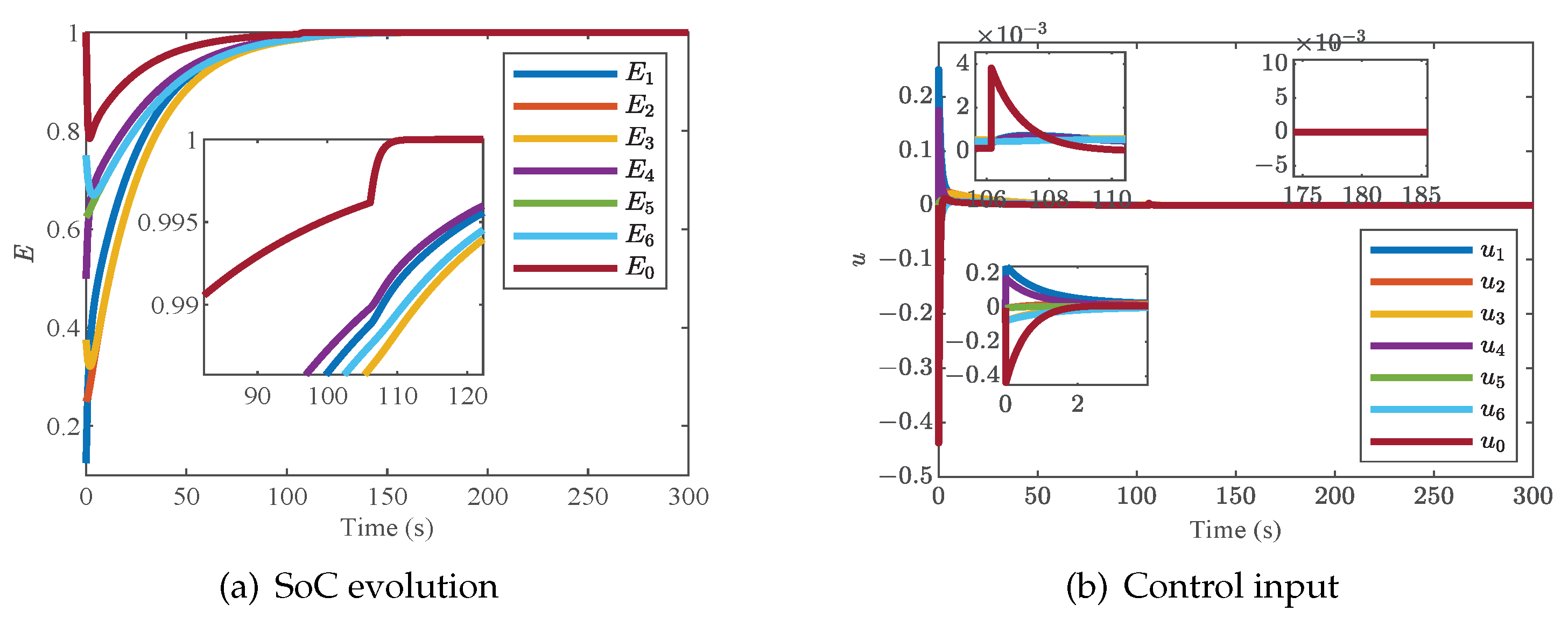
4.1. Case 1: Validation of the Proposed Distributed Charging Strategy with a ME-Based Smart Leader
This case is designed to verify the effectiveness of the designed scheme with an ME-based smart leader. The parameters
,
and
are chosen. The six agent communicate with each other through the topology graph shown in
Figure 3. Additionally, the simulation results are described in
Figure 4a,b.
It can be observed clearly in
Figure 4a,b that the state of the modified dynamic leader can be close to the followers in the evolution process until reaching the threshold. Then, the state of the virtual leader is no longer regulated by followers and finally converges to the reference value. As a result, the SoC of each battery can converge to the reference value, and the control input converges to zero.
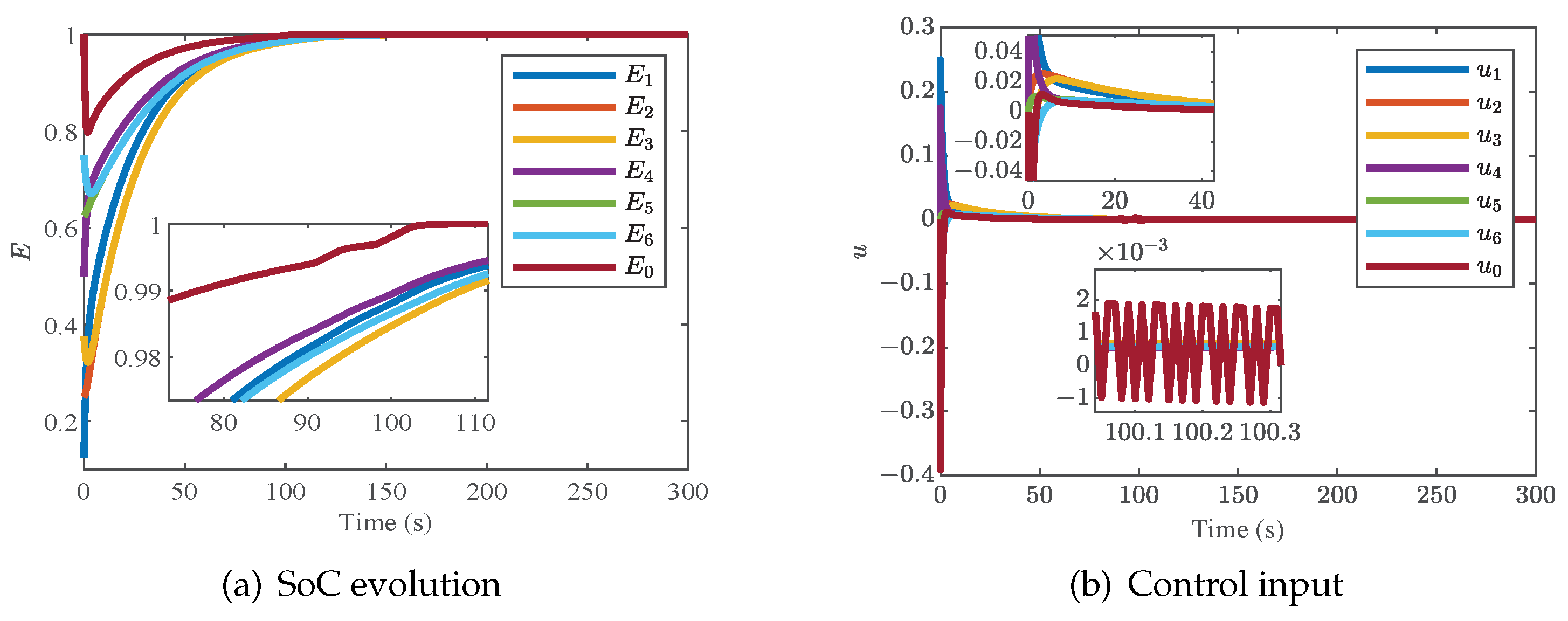
4.2. Case 2: Validation of the Proposed Distributed Charging Strategy with a WE-Based Smart Leader
Under the same conditions as the initial value of SoC in Case 1, the distributed charging strategy with a WE-based smart leader is tested in this case. Here,
,
and
are given. The simulation results are shown in
Figure 5a,b.
It can be observed in
Figure 5a,b that the constant leader is also successfully transformed into a dynamic leader, and the control input of the smart leader oscillates when the controller switches. The state and the control input of the smart leader and followers can converge to 1 and 0, respectively.
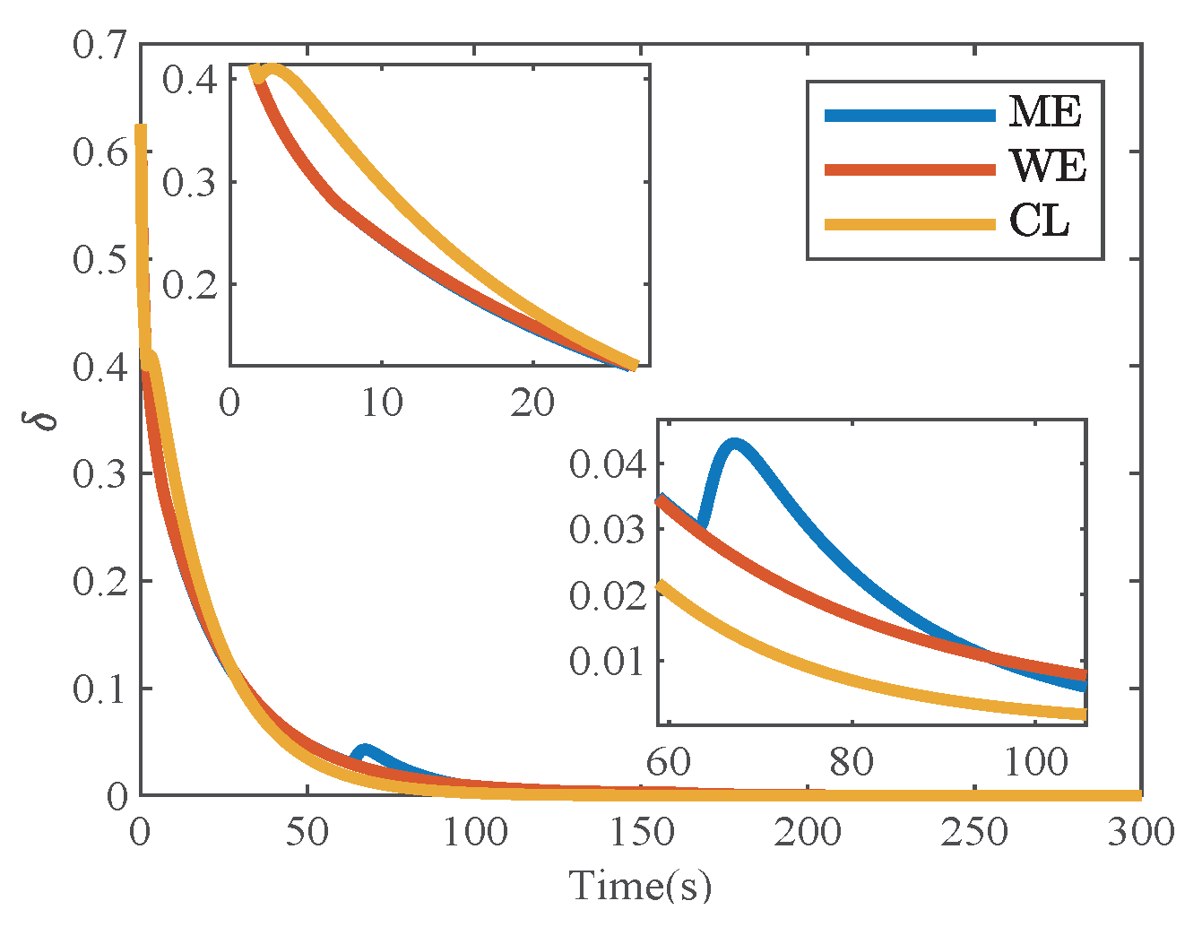
4.3. Case 3: Comparison of Controller Performance under Different Strategies
To illustrate the superiority, the two designed distributed charging strategies are compared with the distributed charging strategy based on the constant leader (CL) on the SoC imbalance index
. The parameters
,
and
are given. The simulation result is shown in
Figure 6.
It can be clearly seen in
Figure 6 that with the support of the two designed distributed charging strategies, SoC imbalance is effectively suppressed. In addition, when the dynamic of the smart leader switches, the distributed charging strategy with the WE-based smart leader is batter than the one with the ME-based smart leader on the imbalance index.
Consequently, when batteries encounter a large SoC imbalance, enabling smart leadership can inhibit SoC imbalance, especially for a WE-based smart leader. However, it has to be pointed out that when SoC imbalance is at a low level, SoC imbalance under the constant leadership is lower. What is worse, SoC imbalance rebounds under the ME-based smart leader when the controller switches.
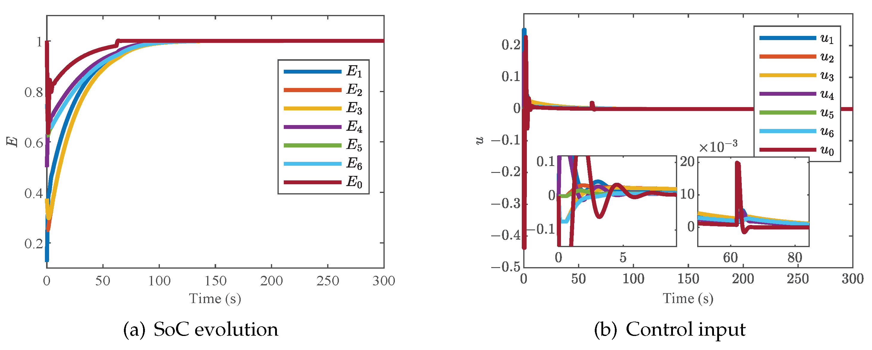
4.4. Case 4: The Two Different Strategies with Input Delay
Here, we arrange this case to verify the performance of the two designed strategies against input delay. Assume that a unified input delay
exists in both two controllers, and the other parameters are the same as those in Cases 1 and 2. The simulation results are exhibited in
Figure 7 and
Figure 8.
As a whole, the input delay does not affect the stability of SoC and the completion of charging. However, the input time delay causes some oscillation in the SoC and the control input. When the time comes to the controller switching, the oscillation of the control input of the ME-based smart leader is larger than that of a WE-based smart leader, while as for the oscillation frequency, the conclusion is just the opposite.
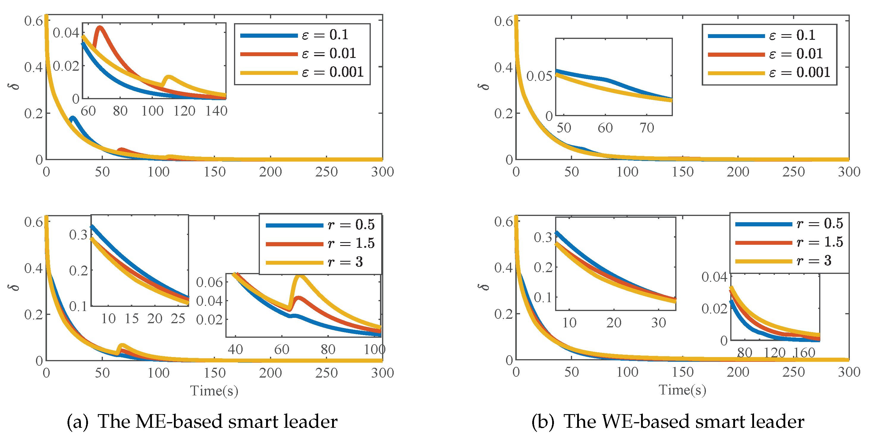
4.5. Case 5: Influence of Parameters and r on Simulation Result
In this paper, there are two parameters related to smart leadership,
and
r, which affect control performance. Here, we study the influence of these two parameters on SoC imbalance one by one with the given
. SoC imbalance indexes are compared under different parameters, which are shown in
Figure 9a,b.
It can be observed that as decreases, the duration of the ME-based smart leadership increases, while the change in has little impact on . The smaller the parameter, the stronger the inhibition of SoC imbalance in the early stage. Likewise, under the two leaderships, SoC imbalance can be better suppressed at the early stage with larger r, and this phenomenon is just the opposite in the later stage. In addition, SoC imbalance has a tiny rebound in the later stage under an ME-based smart leader.
4.6. Case 6: Oscillatory Behavior Discussion
This case is arranged to analyze SoC oscillation caused by input time delay, taking a WE-based smart leader as an example. Under the conditions of
,
and
, three different input delays,
,
and
, are considered in the controller. Additionally, SoCs and SoC imbalance
are shown in
Figure 10a,b respectively.
It can be clearly observed in
Figure 10a,b that an increase in input delay causes more violent oscillation of each agent’s state, especially the smart leader and SoC imbalance index. However, by reducing
r to
, as shown in
Figure 11, the oscillation amplitude of each agent’s state decreases. Combined with the related conclusion in Case 5, there is a trade-off between suppressing the imbalance and mitigating the oscillations caused by input time delay.
4.7. Case 7: Communication Failure
Here, we arrange a case for communication failure. We adopt the following communication failure scenarios. At the beginning, the communication failure did not occur. Until
and
, communication failures occur, respectively, as shown in
Figure 12. The simulations of the two algorithms are shown in
Figure 13 and
Figure 14, respectively.
From the simulation results, some communication failures have some impact on the control performance. By comparing
Figure 4 and
Figure 13 and
Figure 5 and
Figure 14, it can be found that the duration of the smart leadership is significantly shortened in the ME-based smart leader and prolonged in the WE-based smart leader. Additionally, at the time of controller switching, the oscillation amplitude of the two control inputs increases.


