Communication

The Application of Fuel-Cell and Battery Technologies in Unmanned Aerial Vehicles (UAVs): A Dynamic Study

by
Hossein Pourrahmani
*,
Claire Marie Isabelle Bernier
and
Jan Van herle
Group of Energy Materials, École Polytechnique Fédérale de Lausanne, 1951 Sion, Switzerland
*
Author to whom correspondence should be addressed.
Batteries 2022, 8(7), 73; https://doi.org/10.3390/batteries8070073
Submission received: 23 June 2022 / Revised: 12 July 2022 / Accepted: 13 July 2022 / Published: 15 July 2022

Abstract

:
The harmful impacts of fossil-fuel-based engines on the environment have resulted in the development of other alternatives for different types of vehicles. Currently, batteries and fuel cells are being used in the automotive industry, while promising progress in the maritime and aerospace sectors is foreseen. As a case study in the aerospace sector, an unmanned aerial vehicle (UAV) was considered. The goal and the novelty of this study are in its analysis of the possibility of providing 960 W of power for a UAV with a weight of 14 kg using a hybrid system of a lithium-ion (Li-ion) battery and proton-exchange membrane fuel cell (PEMFC). The dynamic performance of the system was analyzed considering three different load profiles over time in an optimized condition. PEMFC was the main supplier of power, while the battery intervened when the power load was high for the PEMFC and the system demanded an immediate response to the changes in power load. Additionally, the impacts of the operating temperature and the C-rate of the battery were characterized by the state of the charge of the battery to better indicate the overall performance of the system.

1. Introduction

The harmful influence of fossil fuels on the environment has convinced the authorities to set official targets to 100% phase out the sales or registrations of new internal combustion engines (ICEs) [1]. As alternatives, batteries and fuel cells are suggested to provide the required power for different applications such as cars, buses, and trucks [2]. The combined fuel-cell and battery system has been proven to be a suitable alternative for ICEs in the maritime sector [3]. Although there have been many investigations on the possibility of using integrated fuel-cell and battery systems as the prime mover for different types of vehicles, a limited number of investigations have been developed in the airplane sector [4].
At the current stage, the suggested integrated systems of batteries and fuel cells are not able to provide the required power for huge passenger planes [5], but they can generate the needed electricity to run small-sized planes (around 100 kW to 300 kW); hence, the objective of the current study was related to the domain of unmanned aerial vehicles (UAVs). UAVs are designed to fulfill long and high-altitude flight missions without any people on board [6]. The main applications of UAVs are in the fields of delivering products, aerial photography [7], surveillance [8], agriculture [9], and any type of aerial inspection [10]. Additionally, the applications of the UAVs have attracted the attention of organizations such as the police and public safety to manage transportation more efficiently [11]. UAVs are also able to prepare disaster warnings, participate in recovery operations, and supply medical help to remote areas [12]. The flight duration and flight altitude were shown to be improved when using proton-exchange membrane fuel cells (PEMFCs) as the prime mover of the UAVs [13]. In comparison to conventional engine-based UAVs, PEMFCs have better energy densities and lower specific power densities [14], which enables them to have higher potential usage in low-maneuverability UAVs. However, a concentrated effort should be made to control the parameters such as the size, weight, and cost of both the hydrogen tanks and the fuel cell stack [15]. At the current stage, these parameters are the main barriers to the commercialization of PEMFCs for UAV applications.
PEMFCs, which convert hydrogen to electricity via electrochemical reactions, are considered to be the best option for mobility applications among different types of fuel cells [16]. The current obstacles toward the commercialization of the PEMFCs are the durability [17], water/thermal management [18], waste heat recovery [19], and cost [20]. The utilization of PEMFCs in UAVs can be a promising candidate for high-endurance operation [21]. Benefiting from a low-temperature operation and fast start-up time enables PEMFCs to be utilized in UAVs [22]. The direct generation of electricity without a convoluted energy management system is another advantage of PEMFCs that facilitates their integration into UAVs [23]. However, the low acceleration and power density of PEMFCs has triggered the idea of combining PEMFCs and lithium-ion (Li-ion) batteries [24]. Thus, the integrated system can improve the low range of batteries by maintaining a high acceleration and fast refueling time.
Electrical batteries are widely used in mobility applications [25]. The design of fixed-wing vertical and takeoff landing (VTOL-FW) was made possible by integrating batteries and engines [26]. Traub [27] also characterized the endurance of battery-powered UAVs, indicating that the discharging behavior of the batteries is the main source of uncertainties. The main obstacle of using batteries as the prime mover of UAVs is the existing uncertainties in predicting the remaining charge [28]. In this regard, most flights with battery-powered UAVs are severely conservative in reality. In theory, the utilization of batteries in UAVs leads to better flight times and system configurations; however, the essential chemistry deviates from pragmatic applications. Different types of batteries have been suggested according to the type of application to facilitate the usage of batteries in different domains. A detailed study in this field can also improve the performance of batteries for UAVs.
The well-known nickel manganese cobalt (NMC) and lithium titanite oxide (LTO) Li-ion batteries are considered the most efficient types [29]. Among the existing Li-ion batteries on the market, LTO enjoys the highest performance, lifespan, and safety at higher cost, whereas NMC provides acceptable performance with low cost and high specific energy [30]. In comparison to the batteries, proton-exchange membrane fuel cells (PEMFCs) have faster refueling times and higher ranges [31]; hence, the integration of batteries and fuel cells can address the needs of UAVs.
The utilization of PEMFCs in UAVs results in a size and weight reduction of the system, in addition to improving the flight endurance. Batteries can also ameliorate the acceleration and thrust of the system. Currently, it is believed that fuel cells can be suitable for cruise flight, while batteries are more appropriate for other flight modes. The novelty of this study is in its analysis of the possibility of integrating PEMFC technology into batteries as an alternative to fossil-fuel-based combustion engines for small-sized UAV application. The proposed hybrid system was designed to provide around 960 W of power for a UAV with a weight of 14 kg. A PEMFC was used as the selected type of fuel cell while NMC was the considered type of Li-ion battery. The goal of this study was to characterize the dynamic performance of the current integrated system in an optimized condition. The integrated model of the fuel cell and the battery was developed using MATLAB/Simulink software to be controlled by an energy management system, which provided power to a DC variable power load, representing the different loads of UAV flight. The load was mainly supplied by the fuel cell, while the battery intervened in the following cases:
  • As support when the load was too high for the fuel cell,
  • As support when the fuel cell took too long to respond to a load variation,
  • As additional load when the state of the charge of the battery was low (meaning that the fuel cell recharged the battery).

2. Methodology

In every PEMFC, hydrogen flows inside the cell through the gas flow channels on the anode side, while air goes to the cathode side. The operating temperature of the PEMFC should be around 65 °C to 85 °C while benefiting from optimal humidity to prevent drying or flooding of the membrane. In this regard, a thermal management system and a humidifier are needed, respectively, to maintain the operating temperature range and humidity. Figure 1a shows a detailed schematic of the utilized PEMFC including the hydrogen source at the anode, humidifier at the cathode, and thermal management system. It is worth mentioning that dynamic modeling of the thermal management system and cooling system was established in the considered MATLAB model, thus enabling control of the operating humidity and temperature.
In the integrated system of the fuel cell and battery for UAVs, the battery could easily adapt to the load variation due to the fast response time while the PEMFC provided the main share of the power for the propulsion system. The battery could also charge/discharge to ensure the performance of the PEMFC at the nominal power using an optimal energy management system (EMS). Figure 1b shows a schematic of the utilized battery system for the UAV application, which was simulated and modeled in MATLAB, comprising a temperature management system to simulate the operating temperature, a controller for the state of the charge (SOC), and battery cells. A battery is composed of cells either in series or in parallel. Once the cells are in series, the voltage of each cell is summed up in the constant current density. In parallel cells, the voltage remains unchanged once the current densities are summed up.
Figure 2 also illustrates the integrated system of the PEMFC and battery given in Figure 1a,b, respectively. Figure 2 emphasizes the role of the EMS in utilizing a specified plan to control the power usage from the battery and fuel cell. An optimum EMS results in better performance of the integrated system and a higher lifetime of the components by optimizing the energy availability. The EMS also manages the different parameters of the system such as the air/fuel pressure, temperature, and humidity for the PEMFC, in addition to the charging/discharging behavior of the battery. The EMS monitors the power load and decides how the power should be provided; hence, it determines the power loads on the battery or the PEMFC. A current controller is also needed in the battery system to simulate the ideal current density for the flight.
Considering the nominal performance of the fuel cell and the state of charge (SOC) of the battery, the EMS can work under different states to optimize the performance of the system. In other words, specified plans are defined once the energy provider (here, either the battery or the PEMFC) reaches a limitation point. These limitation points are the extremum values of the power in the battery and PEMFC ( P m a x B a t t e r y ,   P m i n B a t t e r y , P m a x F C , and P m i n F C ) and the SOC in the battery ( S O C m a x and S O C m i n ). High SOC values are defined once the battery is at more than 80% of its charge, a normal SOC is between 20% and 80%, and a low SOC is below 20%. Accordingly, the following EMS operational states were simulated in the MATLAB model:
  • State (1) P l o a d     P m a x F C and SOC: In this condition, the PEMFC works between the rated and the minimum powers.
  • State (2) P l o a d > P m a x F C + P m a x B a t t e r y and high SOC: This case will not happen as the capacities of the PEMFC and battery were designed properly.
  • State (3) P l o a d = P m a x F C ,   P m a x F C + P m a x B a t t e r y and high SOC: The PEMFC works at the maximum power, while the SOC is reduced. The operating power of the battery is P m a x B a t t e r y = P l o a d P m a x F C .
  • State (4) P l o a d < P F C and normal SOC: In this condition, the battery can be charged, and, if the battery reaches a high SOC, the hybrid system goes to state (1).
  • State (5) P l o a d = P F C , P m a x F C and normal SOC: In this situation, the SOC is enhanced, while the PEMFC works at constant power while the battery is being charged.
  • State (6) P l o a d     P m a x F C and normal SOC: The SOC is reduced at the maximum power of the PEMFC, similar to state (3).
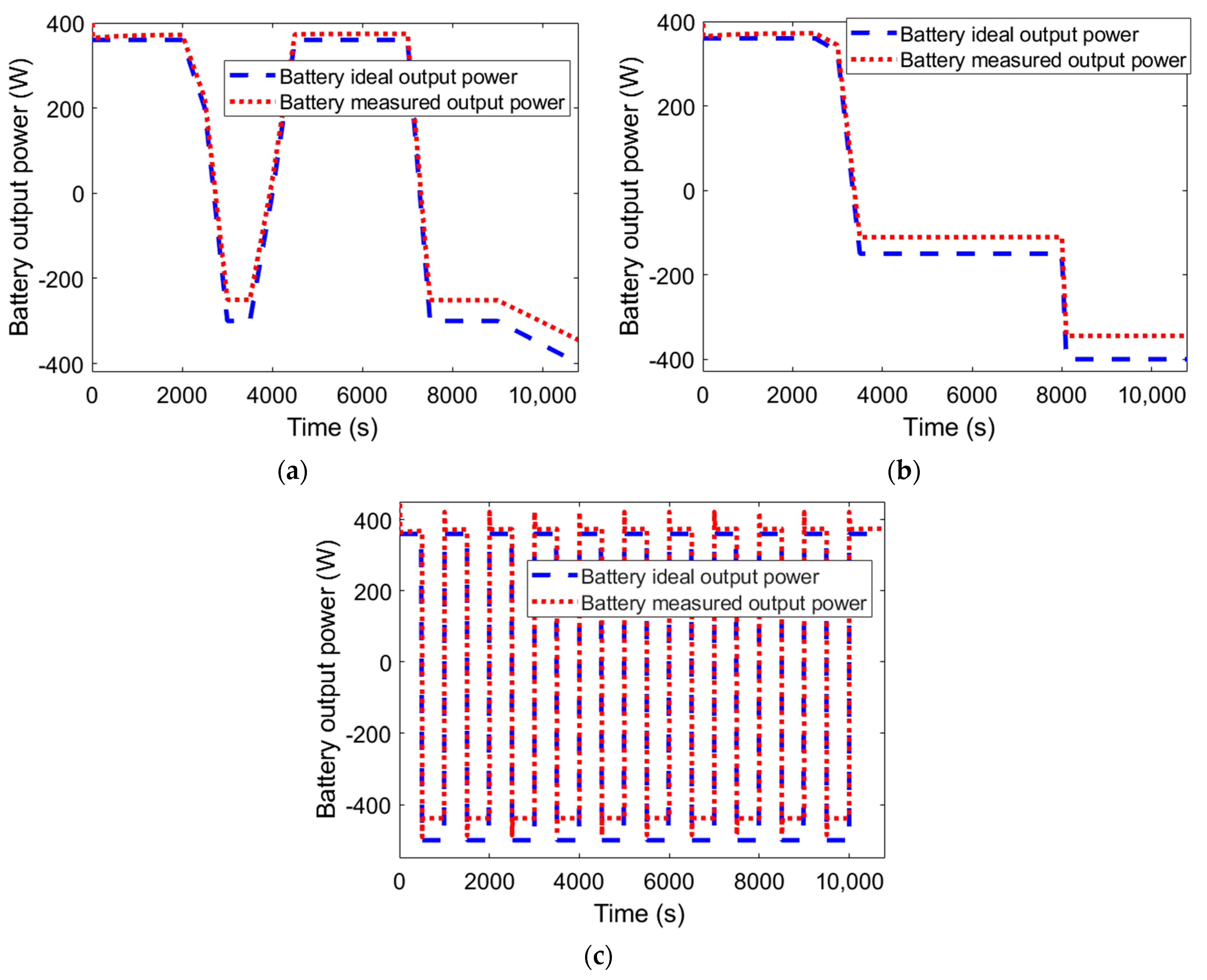
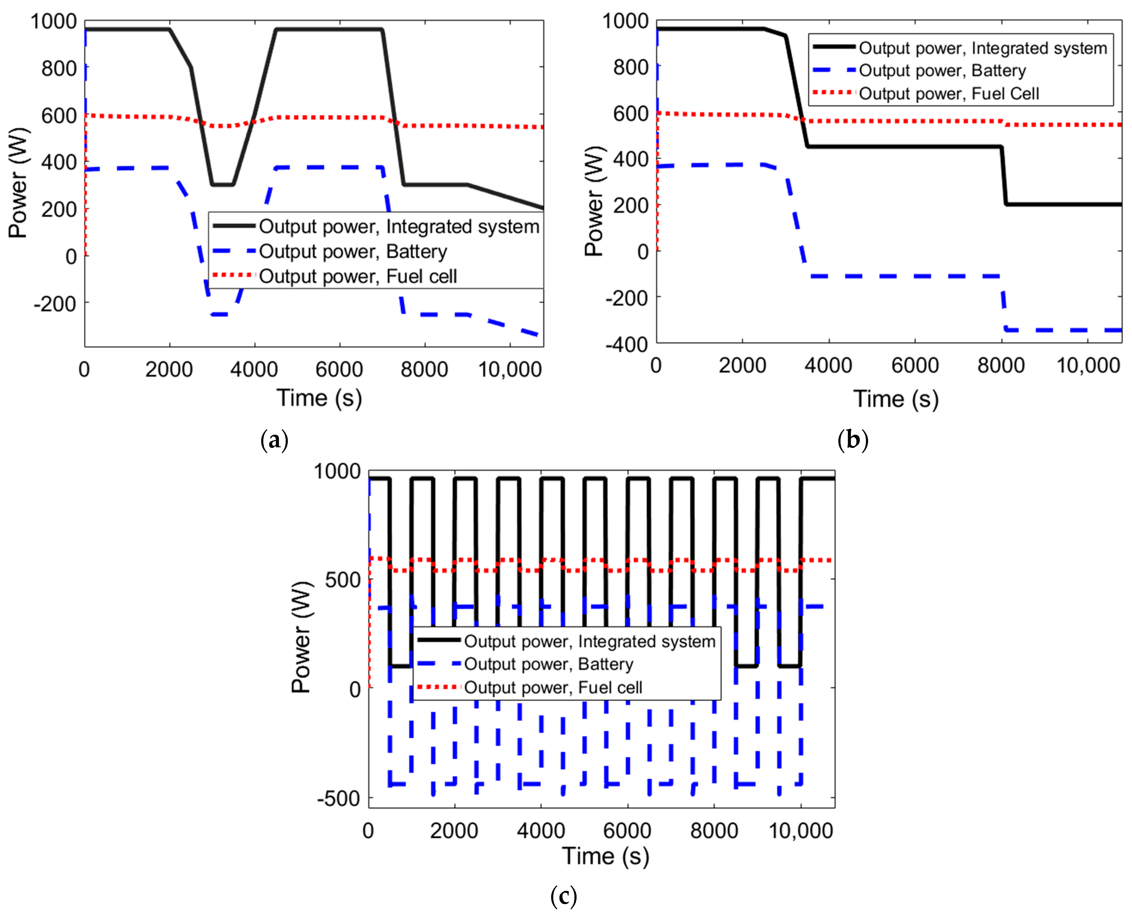
Furthermore, these operational states were implemented with the selection of a conditional switch. Therefore, the following modes were implemented:
  • First, if S O C > 0.2   and P l o a d > 600   W (the nominal output of the fuel cell), the battery goes through discharging, given the conditions in state (3) and state (6).
  • Second, if the S O C < 0.8 and the load is below 600 W, the battery is charged, indicating state (4) and state (5).
  • Third, if the load is below 600 W and the S O C > 0.8 , the battery is not used, signifying state (1).
In addition to determining the considered EMS for the integrated system, the components should be selected deliberately to ensure the optimal performance of the system. Table 1 presents the specification of the selected NMC type Li-ion battery with 18,650 Li-ion cylindrical cells packed within black PVC shrink wrap. The battery benefited from a built-in battery management system to prevent over-charge, over-discharge, over-current, and short-circuits. Furthermore, Table 2 demonstrates the specifications of the devised PEMFC in the proposed integrated system for the UAV.

3. Results and Discussion

The suggested hybrid system operates in a way that the fuel cell is directly connected to the power load, while the battery is integrated into the system with a converter to control the charging and discharging. The battery provides the power when the fuel cell is not able to reach the power load demand. In this condition, the battery is selected with the minimum energy storage capacity, which is beneficial considering the better performance of the fuel cell at lower power levels. Additionally, the battery pack is charged when the power load is lower than the average and discharged when the power load is higher according to the given state conditions in Section 2. To analyze the dynamic performance of the suggested integrated system of the fuel cell and battery to be utilized in the UAV application, three different power demand profiles were considered, as shown in Figure 3. It is worth mentioning that all three considered power demand profiles may happen during the operation of the UAV, as they are close to the practical application environment.
The main idea behind analyzing the three different power demand profiles given in Figure 3 was to characterize the dynamic responses of the UAV under unexpected conditions during the flight. In other words, the system’s response was analyzed once sudden and sharp changes occurred in the power demand, which is similar to the flight mission of a UAV. Figure 4 shows the overall output power of the system according to the given power demand profiles in Figure 3. As can be seen, the fuel cell is considered to constantly provide the main share of the needed power demand, while the battery is expected to be discharged once there is a peak in power demand. Charging of the battery occurs when the power demand is lower than the generated power by the fuel cell. Figure 4 also illustrates that the dynamic responses of the battery are faster than those of the fuel cell and, hence, more suitable for the acceleration and deceleration of the system during flight.
Figure 5 shows the ideal and measured profiles of the generated power by the battery in response to the power demand profiles given in Figure 3. As can be seen, after each drop in the power demand profile, starting from the 2000 s in the first profile (Figure 3a), 3000 s in the second profile (Figure 3b), and 500 s in the third profile (Figure 3c), the battery should be charged ideally less than measured. The reason behind this difference is due to the fuel cell controller that tries to prevent fuel starvation. Moreover, comparing Figure 4 and Figure 5, it is demonstrated that, once a change occurs in the power demand profile, mild changes happen in the power provided by the fuel cell. This stems from the fact that the fuel-cell and battery voltages are linked through diodes on the power management board; hence, a lower battery power leads to lower power settings in the fuel cell.
In analyzing the performance of the batteries, two terms are used: the state of charge (SOC) and depth of discharge (DoD). In batteries, the SOC is the ratio of the level of charge to that of the capacity, while the DoD is the opposite value of the SOC. In other words, the DoD refers to the maximum percentage of the battery’s capacity that is omitted from the charged battery on a regular basis. It is worth mentioning that the term “charged” is related to the SOC, where the battery stops being charged [32]. When batteries are used in vehicles as the energy provider, the SOC for the battery pack is similar to a fuel gauge for gasoline-based vehicles. Figure 6 illustrates the value of the SOC in the hybrid system containing the battery and fuel cell designed for use in a UAV according to the different power demand profiles given in Figure 3. Figure 7 shows the impact of the operating temperature on the respective values of the SOC during the operation of the hybrid system. As can be seen, a higher operating temperature resulted in better SOC values; however, it should not be neglected that higher temperatures also result in higher degradation, thus requiring an appropriate balance.
In addition to the SOC and DoD, another parameter used in characterizing the performance of the batteries is the C-rate. The C-rate determines the speed of charging or discharging for an arbitrary battery [33]. For example, 2C indicates that full charging of a battery from 0% to 100% will take 2 h. Figure 8 illustrates the corresponding values of the battery’s SOC at different C-rates. As can be seen, lower C-rates result in better SOC values, and they benefit from lower charging times. Furthermore, as shown in Table 1, the standard charging and discharging C-rates of the utilized batteries in the current study were 0.5C and 0.2C, respectively, with corresponding values of 1C and 5/3C for the maximum charging and discharging. As can be seen in Figure 8, increasing the maximum charging and discharging C-rate to 2C resulted in considerable performance reduction.

4. Conclusions

Currently, finding suitable alternatives to internal combustion engines (ICEs) is an attractive topic for researchers aimed at saving the environment and reducing harmful emissions. In this regard, fuel cells are suggested, which use hydrogen as fuel, benefiting from better efficiency and zero emissions of carbon and other pollutants to the environment. Although they benefit from a high distance range and fast refueling time, which make them an appropriate option for UAVs, the dynamic responses of these devices are not fast enough to react to changes in the power load typical for UAVs. Batteries are suitable candidates considering their high acceleration and fast response to changes in the power load; however, their low range prevents them from being used in UAVs. In this regard, a hybrid system featuring a battery and fuel cell was suggested in this study to benefit from their fast dynamic response and high range for UAV missions.
Using an energy management system, the results indicated that the performance of the battery was better at higher operating temperatures and lower C-rates. It was also proven that the battery could quickly respond to changes in the power demand during a flight mission, while the fuel cell can generated constant power for flight operation and charging of the battery.
It should be noted that the focus of the current study was on the overall performance of the integrated system of the battery and fuel cell. The dynamic responses of the system were examined with different power load demands to monitor the stability of the system in response to unexpected conditions during flight, which is quite probable in any UAV mission. However, as a topic for future studies, it will be interesting to study the impacts of frequent charging/discharging of the Li-ion batteries on their longevity.

Author Contributions

Conceptualization, H.P.; methodology, H.P.; software, C.M.I.B. and H.P.; validation, C.M.I.B.; formal analysis, H.P.; investigation, C.M.I.B.; resources, H.P.; data curation, C.M.I.B.; writing—original draft preparation, H.P.; writing—review and editing, H.P.; visualization, H.P. and C.M.I.B.; supervision, J.V.h.; project administration, H.P. All authors have read and agreed to the published version of the manuscript.

Funding

This project received funding from the European Union’s Horizon 2020 research and innovation program under the Marie Sklodowska-Curie grant agreement No. 754354.

Institutional Review Board Statement

Not applicable.

Informed Consent Statement

Not applicable.

Data Availability Statement

Available upon formal request.

Conflicts of Interest

The authors declare no conflict of interest.

References

  1. Pandyaswargo, A.H.; Wibowo, A.D.; Maghfiroh, M.F.; Rezqita, A.; Onoda, H. The Emerging Electric Vehicle and Battery Industry in Indonesia: Actions around the Nickel Ore Export Ban and a SWOT Analysis. Batteries 2021, 7, 80. [Google Scholar] [CrossRef]
  2. Kotak, B.; Kotak, Y.; Brade, K.; Kubjatko, T.; Schweiger, H.-G. Battery Crush Test Procedures in Standards and Regulation: Need for Augmentation and Harmonisation. Batteries 2021, 7, 63. [Google Scholar] [CrossRef]
  3. Gay, M.; Pourrahmani, H.; Van Herle, J. Fuel cell and battery technologies for a 800 kW ferry: Two optimized scenarios. Sci. Talks 2022, 3, 100039. [Google Scholar] [CrossRef]
  4. Pelegov, D.V.; Pontes, J. Main Drivers of Battery Industry Changes: Electric Vehicles—A Market Overview. Batteries 2018, 4, 65. [Google Scholar] [CrossRef] [Green Version]
  5. Kovachev, G.; Astner, A.; Gstrein, G.; Aiello, L.; Hemmer, J.; Sinz, W.; Ellersdorfer, C. Thermal Conductivity in Aged Li-Ion Cells under Various Compression Conditions and State-of-Charge. Batteries 2021, 7, 42. [Google Scholar] [CrossRef]
  6. Li, Y.; Liang, W.; Xu, W.; Jia, X. Data Collection of IoT Devices Using an Energy-Constrained UAV. In Proceedings of the 2020 IEEE International Parallel and Distributed Processing Symposium (IPDPS), New Orleans, LA, USA, 18–22 May 2020; pp. 644–653. [Google Scholar]
  7. Li, X.; Yang, L. Design and Implementation of UAV Intelligent Aerial Photography System. In Proceedings of the 2012 4th International Conference on Intelligent Human-Machine Systems and Cybernetics, Nanchang, China, 26–27 August 2012; Volume 2, pp. 200–203. [Google Scholar]
  8. Perez, D.; Maza, I.; Caballero, F.; Scarlatti, D.; Casado, E.; Ollero, A. A ground control station for a multi-UAV surveillance system. J. Intell. Robot. Syst. 2013, 69, 119–130. [Google Scholar] [CrossRef]
  9. Tsouros, D.C.; Bibi, S.; Sarigiannidis, P.G. A Review on UAV-Based Applications for Precision Agriculture. Information 2019, 10, 349. [Google Scholar] [CrossRef] [Green Version]
  10. Yahya, Z.; Imane, S.; Hicham, H.; Ghassane, A.; Bouchini-Idrissi Safia, E. Applied imagery pattern recognition for photovoltaic modules’ inspection: A review on methods, challenges and future development. Sustain. Energy Technol. Assess. 2022, 52, 102071. [Google Scholar] [CrossRef]
  11. Gupta, L.; Jain, R.; Vaszkun, G. Survey of Important Issues in UAV Communication Networks. IEEE Commun. Surv. Tutor. 2016, 18, 1123–1152. [Google Scholar] [CrossRef] [Green Version]
  12. Mao, R.; Du, B.; Sun, D.; Kong, N. Optimizing a UAV-based emergency medical service network for trauma injury patients. In Proceeding of the 2015 IEEE 15th Conference onAutomation Science and Engineering (CASE), Vancouver, BC, Canada, 22–26 August 2019; pp. 721–726. [Google Scholar]
  13. Herwerth, C.; Chiang, C.; Ko, A.; Matsuyama, S.; Choi, S.B.; Mirmirani, M.; Gamble, D.; Paul, R.; Sanchez, V.; Arena, A.; et al. Development of a small long endurance hybrid PEM fuel cell powered UAV. In Proceedings of the 2007 Aerospace Technology Conference and Exposition, Long Beach, CA, USA, 18–20 September 2007. [Google Scholar] [CrossRef]
  14. Nguyen, T.-T.; Fushinobu, K. Effect of operating conditions and geometric structure on the gas crossover in PEM fuel cell. Sustain. Energy Technol. Assess. 2020, 37, 100584. [Google Scholar] [CrossRef]
  15. González-Espasandín, Ó.; Leo, T.J.; Navarro-Arévalo, E. Fuel cells: A real option for unmanned aerial vehicles propulsion. Sci. World J. 2014, 2014, 497642. [Google Scholar] [CrossRef] [PubMed] [Green Version]
  16. Pourrahmani, H.; Van herle, J. Water management of the proton exchange membrane fuel cells: Optimizing the effect of microstructural properties on the gas diffusion layer liquid removal. Energy 2022, 256, 124712. [Google Scholar] [CrossRef]
  17. Wu, J.; Yuan, X.Z.; Martin, J.J.; Wang, H.; Zhang, J.; Shen, J.; Wu, S.; Merida, W. A review of PEM fuel cell durability: Degradation mechanisms and mitigation strategies. J. Power Sources 2008, 184, 104–119. [Google Scholar] [CrossRef]
  18. Pourrahmani, H.; Van herle, J. The impacts of the gas diffusion layer contact angle on the water management of the proton exchange membrane fuel cells: Three-dimensional simulation and optimization. Int. J. Energy Res. 2022. [Google Scholar] [CrossRef]
  19. Pourrahmani, H.; Shakeri, H.; Van herle, J. Thermoelectric Generator as the Waste Heat Recovery Unit of Proton Exchange Membrane Fuel Cell: A Numerical Study. Energies 2022, 15, 18. [Google Scholar] [CrossRef]
  20. Pourrahmani, H.; Gay, M.; Van herle, J. Electric vehicle charging station using fuel cell technology: Two different scenarios and thermodynamic analysis. Energy Rep. 2021, 7, 6955–6972. [Google Scholar] [CrossRef]
  21. Wang, Y.; Ruiz Diaz, D.F.; Chen, K.S.; Wang, Z.; Adroher, X.C. Materials, technological status, and fundamentals of PEM fuel cells—A review. Mater. Today 2020, 32, 178–203. [Google Scholar] [CrossRef]
  22. Bahari, M.; Rostami, M.; Entezari, A.; Ghahremani, S.; Etminan, M. Performance evaluation and multi-objective optimization of a novel UAV propulsion system based on PEM fuel cell. Fuel 2022, 311, 122554. [Google Scholar]
  23. Depcik, C.; Cassady, T.; Collicott, B.; Burugupally, S.P.; Li, X.; Alam, S.S.; Arandia, J.R.; Hobeck, J. Comparison of lithium ion Batteries, hydrogen fueled combustion Engines, and a hydrogen fuel cell in powering a small Unmanned Aerial Vehicle. Energy Convers. Manag. 2020, 207, 112514. [Google Scholar] [CrossRef]
  24. Dudek, M.; Tomczyk, P.; Wygonik, P.; Korkosz, M.; Bogusz, P.; Lis, B. Hybrid fuel cell–battery system as a main power unit for small unmanned aerial vehicles (UAV). Int. J. Electrochem. Sci 2013, 8, 8442–8463. [Google Scholar]
  25. Baazouzi, S.; Rist, F.P.; Weeber, M.; Birke, K.P. Optimization of Disassembly Strategies for Electric Vehicle Batteries. Batteries 2021, 7, 74. [Google Scholar] [CrossRef]
  26. Dündar, Ö.; Bilici, M.; Ünler, T. Design and performance analyses of a fixed wing battery VTOL UAV. Eng. Sci. Technol. Int. J. 2020, 23, 1182–1193. [Google Scholar] [CrossRef]
  27. Traub, L.W. Validation of endurance estimates for battery powered UAVs. Aeronaut. J. 2013, 117, 1155–1166. [Google Scholar] [CrossRef]
  28. Saha, B.; Koshimoto, E.; Quach, C.C.; Hogge, E.F.; Strom, T.H.; Hill, B.L.; Vazquez, S.L.; Goebel, K. Battery health management system for electric UAVs. In Proceedings of the 2011 Aerospace Conference, Big Sky, MT, USA, 5–12 March 2011; pp. 1–9. [Google Scholar]
  29. Wang, L.; Chen, Y.; Wen, X.; Li, J.; Meng, P.; Tao, S. Preparation of Li1.2Ni0.2Mn0.6O2 hollow stratified sphere by self-template method and surface vulcanization. Sustain. Energy Technol. Assess. 2022, 52, 102006. [Google Scholar] [CrossRef]
  30. Da Silva Lima, L.; Quartier, M.; Buchmayr, A.; Sanjuan-Delmás, D.; Laget, H.; Corbisier, D.; Mertens, J.; Dewulf, J. Life cycle assessment of lithium-ion batteries and vanadium redox flow batteries-based renewable energy storage systems. Sustain. Energy Technol. Assess. 2021, 46, 101286. [Google Scholar] [CrossRef]
  31. Bayat, M.; Özalp, M.; Gürbüz, H. Comprehensive performance analysis of a high-temperature PEM fuel cell under different operating and design conditions. Sustain. Energy Technol. Assess. 2022, 52, 102232. [Google Scholar] [CrossRef]
  32. Charfi, S.; Atieh, A.; Chaabene, M. The effect of batteries DOD range setting values on diesel engine generator pollution and overall cost of a hybrid solar/diesel/battery system. In Proceedings of the 2016 International Renewable and Sustainable Energy Conference (IRSEC), Marrakech, Morocco, 14–17 November 2016; pp. 956–960. [Google Scholar]
  33. Li, J.; Wang, D.; Pecht, M. An electrochemical model for high C-rate conditions in lithium-ion batteries. J. Power Sources 2019, 436, 226885. [Google Scholar] [CrossRef]
Figure 1. The proposed design of the fuel-cell and battery units in the suggested hybrid system: (a) detailed schematic of the fuel-cell unit, (b) detailed schematic of the battery unit.
Batteries 08 00073 g001aBatteries 08 00073 g001b
Figure 2. The proposed hybrid system of fuel cell and battery for the UAV application.
Batteries 08 00073 g002
Figure 3. Three different considered power demand profiles of the UAV provided by the suggested integrated system of the fuel cell and battery: (a) case 1, (b) case 2, and (c) case 3.
Batteries 08 00073 g003
Figure 4. The overall output power of the integrated system, differentiating the shares of the fuel cell and battery: (a) case 1, (b) case 2, and (c) case 3.
Batteries 08 00073 g004
Figure 5. The load profiles of the output power of the battery in the suggested integrated system of the UAV: (a) case 1, (b) case 2, and (c) case 3.
Batteries 08 00073 g005
Figure 6. The state of charge (SOC) of the considered battery in the suggested integrated system for the UAV.
Batteries 08 00073 g006
Figure 7. The impact of the changes in the operating temperature of the batteries on the output SOC: (a) case 1, (b) case 2, and (c) case 3.
Batteries 08 00073 g007
Figure 8. The impact of changes in the C-rate of the batteries on the output SOC: (a) case 1, (b) case 2, and (c) case 3.
Batteries 08 00073 g008
Table 1. The specification of the utilized NMC battery in the suggested integrated system for the UAV.
ParameterValue
Capacity15 (Ah)
Charging temperature0 °C to 45 °C
Cycle life1000 cycles
Dimension 152 × 122 × 71   ( mm 3 )
Discharging temperature−20 °C to 60 °C
Energy storage360 (Wh)
Internal resistance ( m Ω ) 30   m Ω / 30   m Ω
Maximum charge C-rate1C
Maximum discharge C-rate5/3C
Maximum discharge current15 (A)
Nominal discharge current7.5 (A)
Normal charge current3.0 (A)
Operating and storage humidity60% ± 25% RH
Standard charge C-rate0.5C
Standard discharge C-rate0.2C
Voltage24 (V)
Weight2.3 (kg)
Table 2. The specification of the utilized PEMFC in the suggested integrated system for the UAV.
ParameterValue
Nominal voltage24 (V)
Nominal power600 (W)
Nominal current density 25 (A)
Number of cells255 cells
DC voltage range 22–36 (V)
Hydrogen pressure 0.04–0.06 (MPa)
Hydrogen consumption at nominal power7000 (mL/min)
System weight2.590 kg
System size 205   ×   205   ×   130   ( mm 3 )
Publisher’s Note: MDPI stays neutral with regard to jurisdictional claims in published maps and institutional affiliations.

