
Integrated Arrays of Micro Resistance Temperature Detectors for Monitoring of the Short-Circuit Point in Lithium Metal Batteries


 ,
, 
Abstract
1. Introduction
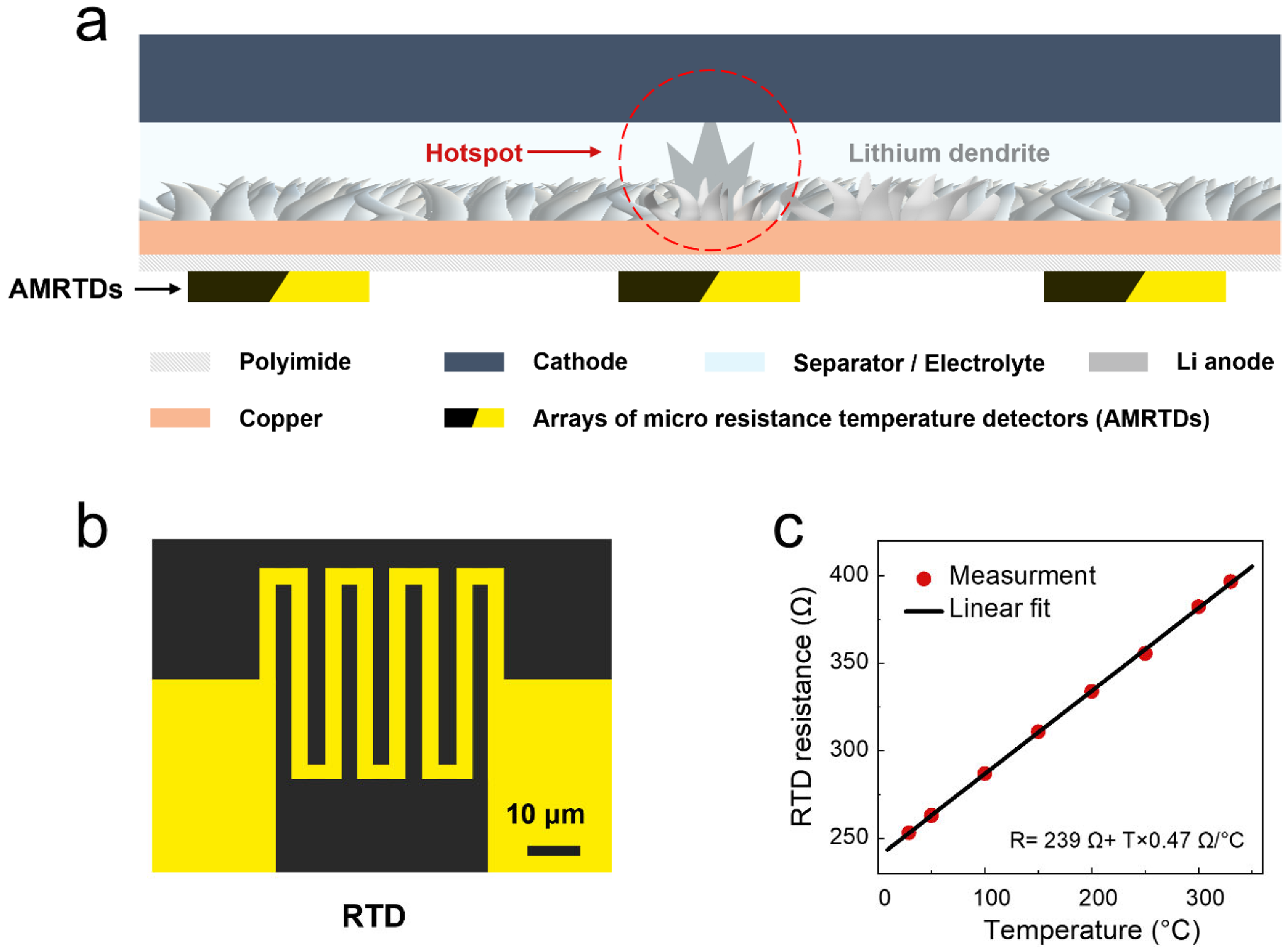
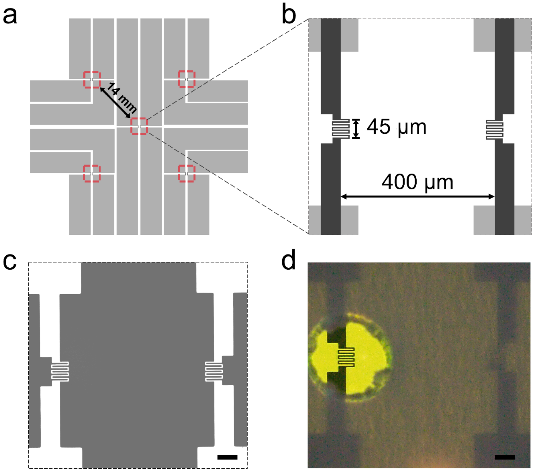
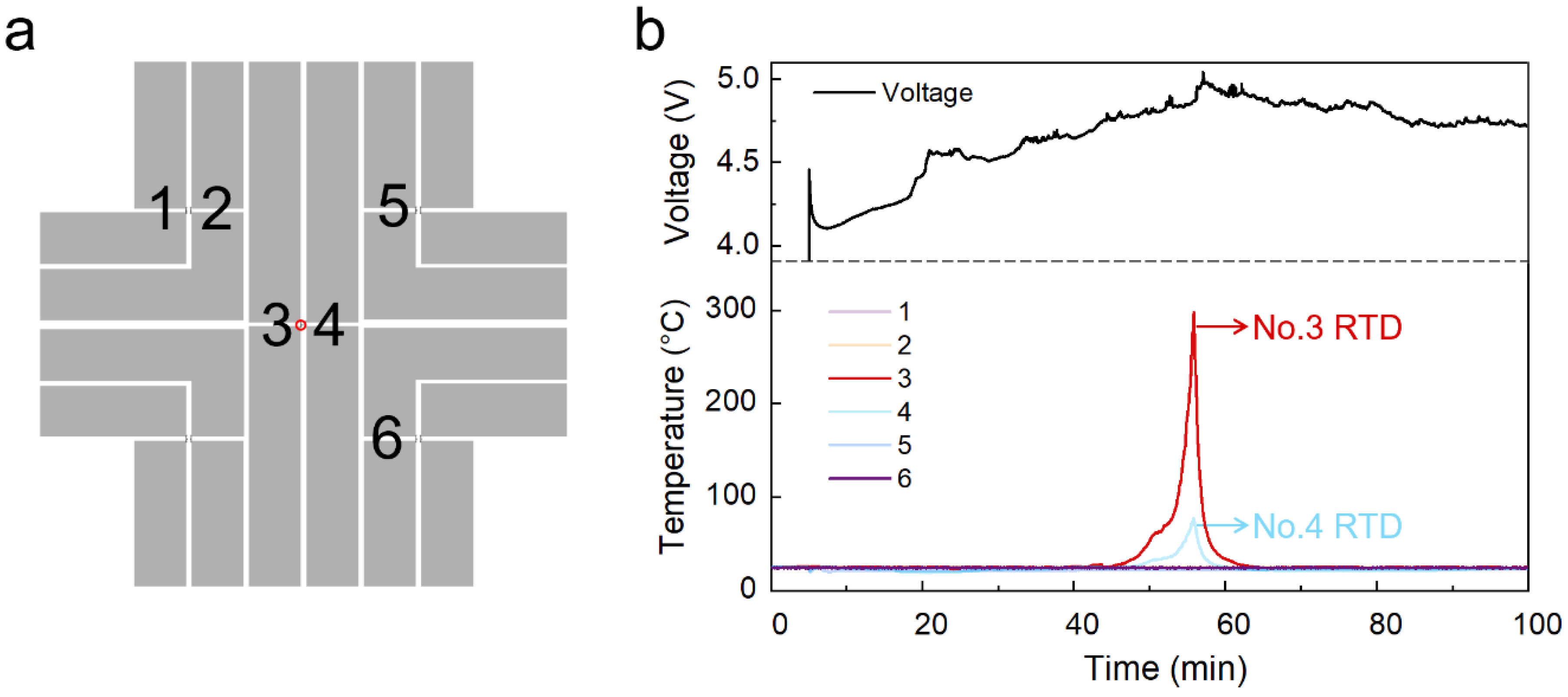
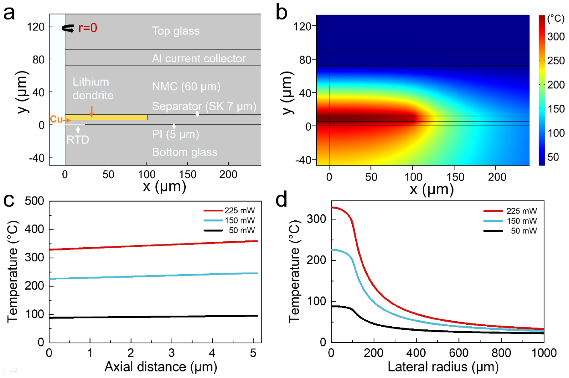
2. Results
3. Materials and Methods
4. Conclusions
Supplementary Materials
Author Contributions
Funding
Data Availability Statement
Acknowledgments
Conflicts of Interest
References
- Larcher, D.; Tarascon, J.-M. Towards Greener and More Sustainable Batteries for Electrical Energy Storage. Nat. Chem. 2015, 7, 19–29. [Google Scholar] [CrossRef] [PubMed]
- Xu, W.; Wang, J.; Ding, F.; Chen, X.; Nasybulin, E.; Zhang, Y.; Zhang, J.-G. Lithium Metal Anodes for Rechargeable Batteries. Energy Environ. Sci. 2014, 7, 513–537. [Google Scholar] [CrossRef]
- Yan, X.; Lin, L.; Chen, Q.; Xie, Q.; Qu, B.; Wang, L.; Peng, D. Multifunctional Roles of Carbon-based Hosts for Li-metal Anodes: A Review. Carbon Energy 2021, 3, 303–329. [Google Scholar] [CrossRef]
- Wang, C.; Adair, K.; Sun, X. All-Solid-State Lithium Metal Batteries with Sulfide Electrolytes: Understanding Interfacial Ion and Electron Transport. Acc. Mater. Res. 2022, 3, 21–32. [Google Scholar] [CrossRef]
- Li, J.; Kong, Z.; Liu, X.; Zheng, B.; Fan, Q.H.; Garratt, E.; Schuelke, T.; Wang, K.; Xu, H.; Jin, H. Strategies to Anode Protection in Lithium Metal Battery: A Review. InfoMat 2021, 3, 1333–1363. [Google Scholar] [CrossRef]
- Liu, B.; Zhang, J.-G.; Xu, W. Advancing Lithium Metal Batteries. Joule 2018, 2, 833–845. [Google Scholar] [CrossRef]
- Chen, X.; Yan, S.; Tan, T.; Zhou, P.; Hou, J.; Feng, X.; Dong, H.; Wang, P.; Wang, D.; Wang, B.; et al. Supramolecular “Flame-Retardant” Electrolyte Enables Safe and Stable Cycling of Lithium-Ion Batteries. Energy Storage Mater. 2022, 45, 182–190. [Google Scholar] [CrossRef]
- Ye, Y.; Chou, L.Y.; Liu, Y.; Wang, H.; Lee, H.K.; Huang, W.; Wan, J.; Liu, K.; Zhou, G.; Yang, Y.; et al. Ultralight and Fire-Extinguishing Current Collectors for High-Energy and High-Safety Lithium-Ion Batteries. Nat. Energy 2020, 5, 786–793. [Google Scholar] [CrossRef]
- Yuan, M.; Liu, K. Rational Design on Separators and Liquid Electrolytes for Safer Lithium-Ion Batteries. J. Energy Chem. 2020, 43, 58–70. [Google Scholar] [CrossRef]
- Cui, Y.; Wan, J.; Ye, Y.; Liu, K.; Chou, L.Y.; Cui, Y. A Fireproof, Lightweight, Polymer-Polymer Solid-State Electrolyte for Safe Lithium Batteries. Nano Lett. 2020, 20, 1686–1692. [Google Scholar] [CrossRef] [PubMed]
- Zhou, G.; Liu, K.; Fan, Y.; Yuan, M.; Liu, B.; Liu, W.; Shi, F.; Liu, Y.; Chen, W.; Lopez, J.; et al. An Aqueous Inorganic Polymer Binder for High Performance Lithium-Sulfur Batteries with Flame-Retardant Properties. ACS Cent. Sci. 2018, 4, 260–267. [Google Scholar] [CrossRef] [PubMed]
- Yuan, S.; Chang, C.; Yan, S.; Zhou, P.; Qian, X.; Yuan, M.; Liu, K. A Review of Fire-Extinguishing Agent on Suppressing Lithium-Ion Batteries Fire. J. Energy Chem. 2021, 62, 262–280. [Google Scholar] [CrossRef]
- Iqbal, S.; Bahadur, A.; Saeed, A.; Zhou, K.; Shoaib, M.; Waqas, M. Journal of Colloid and Interface Science Electrochemical Performance of 2D Polyaniline Anchored CuS/Graphene Nano-Active Composite as Anode Material for Lithium-Ion Battery. J. Colloid Interface Sci. 2017, 502, 16–23. [Google Scholar] [CrossRef] [PubMed]
- Bahadur, A.; Iqbal, S.; Shoaib, M.; Saeed, A. Electrochemical Study of Specially Designed Graphene-Fe3O4-Polyaniline Nanocomposite as a High-Performance Anode for Lithium-Ion Battery. Dalton Trans. 2018, 47, 15031–15037. [Google Scholar] [CrossRef] [PubMed]
- Liu, B.; Jia, Y.; Yuan, C.; Wang, L.; Gao, X.; Yin, S.; Xu, J. Safety Issues and Mechanisms of Lithium-Ion Battery Cell upon Mechanical Abusive Loading: A Review. Energy Storage Mater. 2020, 24, 85–112. [Google Scholar] [CrossRef]
- Xu, J.; Wang, H.; Shi, H.; Mei, X. Multi-Scale Short Circuit Resistance Estimation Method for Series Connected Battery Strings. Energy 2020, 202, 117647. [Google Scholar] [CrossRef]
- Liu, X.; Ren, D.; Hsu, H.; Feng, X.; Xu, G.L.; Zhuang, M.; Gao, H.; Lu, L.; Han, X.; Chu, Z.; et al. Thermal Runaway of Lithium-Ion Batteries without Internal Short Circuit. Joule 2018, 2, 2047–2064. [Google Scholar] [CrossRef]
- Wang, Q.; Mao, B.; Stoliarov, S.I.; Sun, J. A Review of Lithium Ion Battery Failure Mechanisms and Fire Prevention Strategies. Prog. Energy Combust. Sci. 2019, 73, 95–131. [Google Scholar] [CrossRef]
- Abada, S.; Marlair, G.; Lecocq, A.; Petit, M.; Sauvant-Moynot, V.; Huet, F. Safety Focused Modeling of Lithium-Ion Batteries: A Review. J. Power Sources 2016, 306, 178–192. [Google Scholar] [CrossRef]
- Feng, X.; Ouyang, M.; Liu, X.; Lu, L.; Xia, Y.; He, X. Thermal Runaway Mechanism of Lithium Ion Battery for Electric Vehicles: A Review. Energy Storage Mater. 2018, 10, 246–267. [Google Scholar] [CrossRef]
- Chen, Z.; Xiong, R.; Tian, J.; Shang, X.; Lu, J. Model-Based Fault Diagnosis Approach on External Short Circuit of Lithium-Ion Battery Used in Electric Vehicles. Appl. Energy 2016, 184, 365–374. [Google Scholar] [CrossRef]
- Chombo, P.V.; Laoonual, Y. A Review of Safety Strategies of a Li-Ion Battery. J. Power Sources 2020, 478, 228649. [Google Scholar] [CrossRef]
- Finegan, D.P.; Scheel, M.; Robinson, J.B.; Tjaden, B.; Hunt, I.; Mason, T.J.; Millichamp, J.; Di Michiel, M.; Offer, G.J.; Hinds, G.; et al. In-Operando High-Speed Tomography of Lithium-Ion Batteries during Thermal Runaway. Nat. Commun. 2015, 6, 6924. [Google Scholar] [CrossRef] [PubMed]
- Liu, K.; Liu, Y.; Lin, D.; Pei, A.; Cui, Y. Materials for Lithium-Ion Battery Safety. Sci. Adv. 2018, 4, eaas9820. [Google Scholar] [CrossRef]
- Zhu, Y.; Xie, J.; Pei, A.; Liu, B.; Wu, Y.; Lin, D.; Li, J.; Wang, H.; Chen, H.; Xu, J.; et al. Fast Lithium Growth and Short Circuit Induced by Localized-Temperature Hotspots in Lithium Batteries. Nat. Commun. 2019, 10, 2067. [Google Scholar] [CrossRef]
- Abaza, A.; Ferrari, S.; Wong, H.K.; Lyness, C.; Moore, A.; Weaving, J.; Blanco-Martin, M.; Dashwood, R.; Bhagat, R. Experimental Study of Internal and External Short Circuits of Commercial Automotive Pouch Lithium-Ion Cells. J. Energy Storage 2018, 16, 211–217. [Google Scholar] [CrossRef]
- Maleki, H.; Howard, J.N. Internal Short Circuit in Li-Ion Cells. J. Power Sources 2009, 191, 568–574. [Google Scholar] [CrossRef]
- Ramadass, P.; Fang, W.; Zhang, Z. Study of Internal Short in a Li-Ion Cell I. Test Method Development Using Infra-Red Imaging Technique. J. Power Sources 2014, 248, 769–776. [Google Scholar] [CrossRef]
- Wang, S.; Li, K.; Tian, Y.; Wang, J.; Wu, Y.; Ji, S. Infrared Imaging Investigation of Temperature Fluctuation and Spatial Distribution for a Large Laminated Lithium–Ion Power Battery. Appl. Therm. Eng. 2019, 152, 204–214. [Google Scholar] [CrossRef]
- Wang, Q.; Ping, P.; Zhao, X.; Chu, G.; Sun, J.; Chen, C. Thermal Runaway Caused Fire and Explosion of Lithium Ion Battery. J. Power Sources 2012, 208, 210–224. [Google Scholar] [CrossRef]
- Saw, L.H.; Somasundaram, K.; Ye, Y.; Tay, A.A.O. Electro-Thermal Analysis of Lithium Iron Phosphate Battery for Electric Vehicles. J. Power Sources 2014, 249, 231–238. [Google Scholar] [CrossRef]
- Ye, Y.; Shi, Y.; Cai, N.; Lee, J.; He, X. Electro-Thermal Modeling and Experimental Validation for Lithium Ion Battery. J. Power Sources 2012, 199, 227–238. [Google Scholar] [CrossRef]
- Liu, H.; Wei, Z.; He, W.; Zhao, J. Thermal Issues about Li-Ion Batteries and Recent Progress in Battery Thermal Management Systems: A Review. Energy Convers. Manag. 2017, 150, 304–330. [Google Scholar] [CrossRef]
- Ren, D.; Feng, X.; Liu, L.; Hsu, H.; Lu, L.; Wang, L.; He, X.; Ouyang, M. Investigating the Relationship between Internal Short Circuit and Thermal Runaway of Lithium-Ion Batteries under Thermal Abuse Condition. Energy Storage Mater. 2021, 34, 563–573. [Google Scholar] [CrossRef]
- Song, W.; Chen, M.; Bai, F.; Lin, S.; Chen, Y.; Feng, Z. Non-Uniform Effect on the Thermal/Aging Performance of Lithium-Ion Pouch Battery. Appl. Therm. Eng. 2018, 128, 1165–1174. [Google Scholar] [CrossRef]
- Walker, W.; Ardebili, H. Thermo-Electrochemical Analysis of Lithium Ion Batteries for Space Applications Using Thermal Desktop. J. Power Sources 2014, 269, 486–497. [Google Scholar] [CrossRef]
- Forgez, C.; Vinh Do, D.; Friedrich, G.; Morcrette, M.; Delacourt, C. Thermal Modeling of a Cylindrical LiFePO4/Graphite Lithium-Ion Battery. J. Power Sources 2010, 195, 2961–2968. [Google Scholar] [CrossRef]
- Li, Z.; Zhang, J.; Wu, B.; Huang, J.; Nie, Z.; Sun, Y.; An, F.; Wu, N. Examining Temporal and Spatial Variations of Internal Temperature in Large-Format Laminated Battery with Embedded Thermocouples. J. Power Sources 2013, 241, 536–553. [Google Scholar] [CrossRef]
- Lin, X.; Perez, H.E.; Siegel, J.B.; Stefanopoulou, A.G.; Li, Y.; Anderson, R.D.; Ding, Y.; Castanier, M.P. Online Parameterization of Lumped Thermal Dynamics in Cylindrical Lithium Ion Batteries for Core Temperature Estimation and Health Monitoring. IEEE Trans. Control Syst. Technol. 2013, 21, 1745–1755. [Google Scholar] [CrossRef]
- Feng, X.; Fang, M.; He, X.; Ouyang, M.; Lu, L.; Wang, H.; Zhang, M. Thermal Runaway Features of Large Format Prismatic Lithium Ion Battery Using Extended Volume Accelerating Rate Calorimetry. J. Power Sources 2014, 255, 294–301. [Google Scholar] [CrossRef]
- Chen, M.; Bai, F.; Lin, S.; Song, W.; Li, Y.; Feng, Z. Performance and Safety Protection of Internal Short Circuit in Lithium-Ion Battery Based on a Multilayer Electro-Thermal Coupling Model. Appl. Therm. Eng. 2019, 146, 775–784. [Google Scholar] [CrossRef]
- Lee, C.Y.; Lee, S.J.; Tang, M.S.; Chen, P.C. In Situ Monitoring of Temperature inside Lithium-Ion Batteries by Flexible Micro Temperature Sensors. Sensors 2011, 11, 9942–9950. [Google Scholar] [CrossRef] [PubMed]
- Cannon, A.; Ryan, E.M. Characterizing the Microstructure of Separators in Lithium Batteries and Their Effects on Dendritic Growth. ACS Appl. Energy Mater. 2021, 4, 7848–7861. [Google Scholar] [CrossRef]


Publisher’s Note: MDPI stays neutral with regard to jurisdictional claims in published maps and institutional affiliations. |
© 2022 by the authors. Licensee MDPI, Basel, Switzerland. This article is an open access article distributed under the terms and conditions of the Creative Commons Attribution (CC BY) license (https://creativecommons.org/licenses/by/4.0/).
Share and Cite
Zhao, L.; Wu, C.; Zhang, X.; Zhang, Y.; Zhang, C.; Dong, L.; Su, L.; Xie, J. Integrated Arrays of Micro Resistance Temperature Detectors for Monitoring of the Short-Circuit Point in Lithium Metal Batteries. Batteries 2022, 8, 264. https://doi.org/10.3390/batteries8120264
Zhao L, Wu C, Zhang X, Zhang Y, Zhang C, Dong L, Su L, Xie J. Integrated Arrays of Micro Resistance Temperature Detectors for Monitoring of the Short-Circuit Point in Lithium Metal Batteries. Batteries. 2022; 8(12):264. https://doi.org/10.3390/batteries8120264
Chicago/Turabian StyleZhao, Lianqi, Cong Wu, Xinshui Zhang, Yue Zhang, Chao Zhang, Lei Dong, Longxing Su, and Jin Xie. 2022. "Integrated Arrays of Micro Resistance Temperature Detectors for Monitoring of the Short-Circuit Point in Lithium Metal Batteries" Batteries 8, no. 12: 264. https://doi.org/10.3390/batteries8120264
APA StyleZhao, L., Wu, C., Zhang, X., Zhang, Y., Zhang, C., Dong, L., Su, L., & Xie, J. (2022). Integrated Arrays of Micro Resistance Temperature Detectors for Monitoring of the Short-Circuit Point in Lithium Metal Batteries. Batteries, 8(12), 264. https://doi.org/10.3390/batteries8120264