Article

High-Yield Preparation of ZnO Nanoparticles on Exfoliated Graphite as Anode Material for Lithium Ion Batteries and the Effect of Particle Size as well as of Conductivity on the Electrochemical Performance of Such Composites

1
ECKART GmbH, A member of ALTANA, 91235 Hartenstein, Germany
2
Department of Materials Processing, Faculty of Engineering Science, Zentrum für Energietechnik (ZET), University of Bayreuth, 95447 Bayreuth, Germany
3
Department of Functional Materials, Faculty of Engineering Science, Zentrum für Energietechnik (ZET), University of Bayreuth, 95447 Bayreuth, Germany
*
Author to whom correspondence should be addressed.
The present work is dedicated to Prof. Dr. Monika Willert-Porada. Prof. Willert-Porada passed away unexpectedly on 11 December 2016 at age of 61. We lost an open minded, highly interdisciplinary and innovative scientist and supervisor.
Batteries 2018, 4(2), 24; https://doi.org/10.3390/batteries4020024
Submission received: 4 April 2018 / Revised: 30 April 2018 / Accepted: 18 May 2018 / Published: 23 May 2018

Abstract

:
The combination of zinc oxide (ZnO) nanoparticles (NP) and graphite provides a promising approach for applications in the field of anode materials for lithium ion batteries. Here, we report a facile and environmentally friendly method yielding uniformly dispersed ZnO particles with a controllable particle size between 5 and 80 nm, supported by exfoliated graphite (EG) sheets. A thermal post-treatment (420 to 800 °C, N2) of ZnO@EG composite results in high yield with the opportunity for industrial scale-up. The post-treatment leads to growing ZnO particles on the EG sheets, while oxygen is disincorporated from ZnO by the associated carbothermal reduction of ZnO@EG composites above 600 °C and the conductivity is increased. ZnO@EG composite anodes, reduced at 600 °C, show improved Li storage capacity (+25%) and good cycle stability, compared to the EG anode. This can be attributed to the increased conductivity, despite the particle size increased up to 80 nm. Furthermore, we suggest that the mechanism for the reaction of Li+ ions with ZnO@EG-composites including ZnO-particles with an average particle size below 20 nm differs from the classical Li+ ions insertion/de-insertion or alloying process.

1. Introduction

Lithium ion batteries (LIB) are important energy storage devices—not only for portable electronic and hybrid/pure electric vehicles but also for stationary storage systems [1,2]. So far, LIBs are the most developed and satisfying energy storage technology due to excellent benefits in terms of high energy density, high voltage, light weight and long cycle life [3,4,5]. Unfortunately, the initial commercial LIB anode composed of a graphite anode exhibits a low theoretical capacity of only 372 mAhg−1 leading to a limited output energy density [6].
Accordingly, many research groups extensively investigated a variety of metal oxides as anode materials due to their high energy densities and higher theoretical capacities (>600 mAhg−1) [7] (Fe3O4 [8], Co3O4 [9,10], MoO2 [11], SnO2 [12,13], NiO [14] and CuO [15],) compared to traditional graphite anodes.
In addition to the above mentioned metal oxides, ZnO is characterized by a high theoretical capacity of 978 mAhg−1 [7], environmental friendliness and low costs [16]. Despite these advantages, ZnO is, like many other metal oxides, poorly electrically conducting at application temperature (1 · 10−2 S/m) [7] and it shows a large volume expansion (228%) caused by a conversion reaction during the lithiation [7], which is much larger than for the lithium intercalation into graphite material (~10%) [17]. The conversion reaction leads to capacity losses due to the structural changes during the lithiation/de-lithiation process including material pulverization and loss of interconnectivity between particles and even active material peeling off from the electrode [16]. The two-step lithiation mechanism of ZnO contains the reduction of ZnO to Zn accompanied by the formation of a Li2O matrix (Equation (1)) and the subsequent formation of a LiZn alloy (Equation (2)) [7].
ZnO   +   2 Li + + 2 e     Zn   +   Li 2 O
Zn   +   Li +   +   e     LiZn
An alloying reaction of Zn with Li is a multi-step process including following steps (Equation (3)) [18,19]:
Zn   Li 2 Zn 5     LiZn 2     Li 2 Zn 3     LiZn
An effective method to buffer the volume changes of metal oxides during the lithiation is the introduction of carbonaceous sheets assembled between the NPs [20,21]. Graphene, for instance, fulfills the necessary requirements for composite formation such as large specific surface area (2630 m2/g) [22], very high electrical in-plane conductivity [23] and excellent mechanical properties [24]. Furthermore, the use of nano-sized particles (abbreviated with NP in the following) minimizes not only the large mechanical stress resulting from the volume expansion/shrinkage, but also provides short diffusion paths for Li+ ions [7]. Hence, a synergy of both materials improves the stability and capacity of the resulting composite material compared to the properties of the individual materials [25].
A common method to produce composites comprised of ZnO and graphene is Hummer´s synthesis route [4,26,27] inducing the application of strong oxidation agents [28,29,30]. The formation of graphene oxide (GO) with functional groups, such as hydroxy, ketone, carboxyl and epoxy groups, induces an increase of the initial lattice space between the single graphene layers from 0.34 nm to 0.74 nm. The next step involves the addition of zinc salt to the GO followed by a reduction. The reduction step includes either the addition of chemical agents like sodium borohydride [28], hydrazine [29], hydrochinone [28], or a thermal reduction. However, the still present unreduced functional groups on the graphene surface are reactive and tend to oxidize the electrolyte at high current densities (500 mAg−1) indicating electrochemical instability in the electrode [7]. Another issue, although only rarely discussed, is the negative effect of inhomogeneously coated particles on the carbonaceous sheets and a broad particle size distribution [31,32]. The application of homogeneously coated ZnO NPs with narrow size distribution on graphene offers more electrochemical active sites, larger electrode/electrolyte interface and shorter diffusion length for Li+ ions insertion resulting in enhanced electrochemical behavior (556 mAhg−1) [21,24], compared to aggregates or inhomogeneously coated ZnO NPs (<300 mAhg−1) [26]. However, high costs, low yield and application of hazard chemicals make the production process not suitable for industrial production scale at the moment.
Previously, we reported a synthesis route to prepare a stable monolayer of highly dispersed ZnO NPs with an average size of 5 nm on an exfoliated graphite (EG) surface [33,34], which is in the following abbreviated as ZnO@EG.
In this work, we introduce a thermal post-treatment of the initial ZnO@EG composites in inert atmosphere easily control the ZnO particle size on the EG sheets, allowing to investigate the effect of ZnO particle size on the electrochemical performance of the composites. The thermal post-treatment also induces a carbothermal reduction of the ZnO@EG composites associated by an improved conductivity due to the oxygen reduction in the ZnO particles accompanied by an enhanced electrochemical performance. To the best of our knowledge, industrially scalable processes yielding uniformly dispersed ZnO particles with a controllable particle size between 5 nm and 80 nm on EG sheets as anode materials for application in LIBs have not been reported.
Depending on the size of adsorbed ZnO particles, a different electrochemical behavior of ZnO@EG composites was obtained. In this study, we provide a model for the lithiation process (Li+ insertion into the ZnO@EG composites) and de-lithiation process (Li+ extraction) depending on the ZnO particle size.

2. Materials and Methods

2.1. Materials

In the present work, graphite (ECOPHIT® G GFG 350) was obtained from SGL Carbon (Wiesbaden, Germany). This graphite exhibits a high carbon content (purity ≥ 95%) and a d50 value between 315 µm and 385 µm. Zinc acetate dihydrate (Zn(CH3COO)2·2H2O, purity ≥ 99%) and lithium hydroxide monohydrate (LiOH·H2O, purity ≥ 99%) were purchased from Sigma Aldrich (Taufkirchen, Germany) The ZnO@EG composites were prepared with isopropanol of technical grade (water content 0.03%). All chemicals were used as received.

2.2. ZnO@EG Composite Formation and Thermal Treatment

The ZnO@EG composites were synthesized according to our previously reported method [33] and used as-prepared for further characterization. Then, the ZnO@EG composites were thermally post-treated in a horizontal furnace (Nabertherm B 150, Nabertherm GmbH, Lilienthal, Germany) under heating to different temperatures (420 °C, 500 °C, 550 °C, 600 °C, 650 °C, 700 °C, 720 °C, 750 °C, and 800 °C) in N2 atmosphere for 1 h. The ZnO@EG composites are abbreviated by ZnO@EG-420 °C to ZnO@EG-800 °C in the following, in accordance with their thermal treatment temperature.

2.3. Characterization

A scanning electron microscope (SEM; Supra 35, Zeiss, Oberkochen, Germany) and a transmission electron microscope (TEM; EM 912 Omega, Zeiss) were used to determine morphology and size distribution of the ZnO@EG composite materials. SEM images were taken at operating voltages of 1 kV and 1.5 kV, respectively. For the cross section images, the ZnO@EG composites were dispersed in a mixture of EpoFix Resin and EpoFix Hardener (25:3) both from Struers, Germany. The mixture was applied on a foil and dried for 24 h at room temperature. The hardened sample was separated mechanically from the foil resulting in a thin slice. The thin slice was again embedded into an epoxy resin and hardened followed by cross-section preparation using the automatic Grinder/Polisher. For TEM images, the samples were dispersed in isopropanol using an ultrasonic bath and deposited on lacey 200 mesh copper grids. The samples were investigated at an acceleration voltage of 200 kV. For each sample, the diameters of more than 100 ZnO particles were measured and averaged. ZnO@EG composites were characterized by an X-ray diffractometer (XRD, Philips, X’Pert MPD PW 3040, EA Almelo, The Netherlands) using a Cu-Kα source. Powder diffraction patterns were recorded at ambient temperature between 2θ = 10° and 2θ = 90°with a step size of 0.02°. The spectra were analyzed using X’Pert HighScore Plus 4.1 software (Version 4.1, Malvern Panalytical Ltd, Malvern, UK). The element composition of the ZnO@EG composites were determined using ICP-OES (Ciros SOP, SPECTRO, Kleve, Germany) with HCl: H2O2 (1:1) mixtures. Simultaneous thermal analysis—mass spectrometry (STA-MS, STA 449 F3 Jupiter, Netzsch, Selb, Germany) was used to determine the ZnO content of the composites and the decomposition products. The samples were analyzed in air between 30 °C and 800 °C at a heating rate of 10 K/min. The signal intensity of the gaseous products during heating in argon was investigated in situ by MS. By energy dispersive X-ray spectroscopy (EDX, X-MaxN 150, Oxford Instruments, Abingdon-on-Thames, UK), the chemical composition of the ZnO@EG composites was investigated at a working distance of (6.0–8.5) mm and an operating voltage of 3 kV.

2.4. Electrochemical Characterization

The electrodes were prepared by mixing ZnO@EG composite material, polyacrylic acid (PAA, Sigma Aldrich, Taufkirchen, Germany), and carbon black (DENKA—Denki Kagaku Kogyo KK, Tokyo, Japan) in a weight ratio of 60:30:10 in methyl-2-pyrrolidinone (NMP, Merck, Darmstadt, Germany). The mixed slurry was uniformly coated with a doctor blade (Zehntner Testing Instruments, ZUA 2000, Sissach, Switzerland) on a copper foil (Schlenk AG, Roth, Germany, purity ≥ 99.98%). The prepared anode sheets were dried at 100 °C in a vacuum oven for 1 h. The layer thickness of the electrodes was about 110 µm. All half-cells were assembled in an Ar-filled glove box using lithium foil (Chempur, purity ≥ 99.8%) as counter electrode and Whatman®GF/C as separator. A 1 M solution of LiPF6 in a mixture of ethylene carbonate and diethyl carbonate at a volume ratio of 1:1 (SelectityleTM LP 30, BASF, Ludwigshafen, Germany) served as an electrolyte. Galvanostatic discharge/charge cycles were conducted at a voltage range between 0.05 V and 2.0 V with a constant current of 0.05 C using a BaSiTec CTS LAB testing station. The C-rate (0.05 C) corresponds to a current density of 21.8 mA/g according to the theoretical capacity of the ZnO@EG composites (435.6 mAh/g). The theoretical capacity of the Zno@EG composites was calculated as follows [35,36]:
c theoretical   =   c EG % mass   of   EG   +   c ZnO % mass   of   ZnO   =   372 mAh g · 89 . 5 %   +   978 mAh g · 10 . 5 %   =   435 . 6 mAh g
By an impedance analyzer (Gamry Instruments, Reference 3000, Haar, Germany), electrochemical impedance spectroscopy (EIS) data were obtained in the frequency range from 1 Hz to 1 MHz prior to the other electrochemical measurements.
All electrochemical measurements were conducted at ambient temperature and pressure.

3. Results and Discussion

3.1. Structure and Morphology of the ZnO@EG Composites

Structure and morphology of the initial and the thermally treated ZnO@EG composites were investigated by SEM and TEM. Figure 1a,d depicts representative top view images of initial ZnO@EG composites. The spherical ZnO NPs with an average particle size of (4.7 ± 0.7) nm are homogeneously distributed on both sides of the EG sheets without observable aggregation. The corresponding histogram, which was obtained from at least 100 ZnO NPs on EG sheets, shows a very narrow size distribution. It should be noted that the ZnO particles are strongly attached to EG sheets—even by ultrasonic treatment they could not be removed [33], indicating a strong interaction between ZnO particles and EG.
Figure 1b,c,e,f shows SEM and TEM images of ZnO@EG-600 °C and ZnO@EG-700 °C composites with corresponding particle size distributions. The observed particle sizes of the adsorbed ZnO NPs increase in both cases from ca. 5 nm (untreated) to approximately 42 nm at 600 °C and to over 77 nm at 700 °C, indicating further growth of the NP during the thermal post-treatment on the EG sheets.
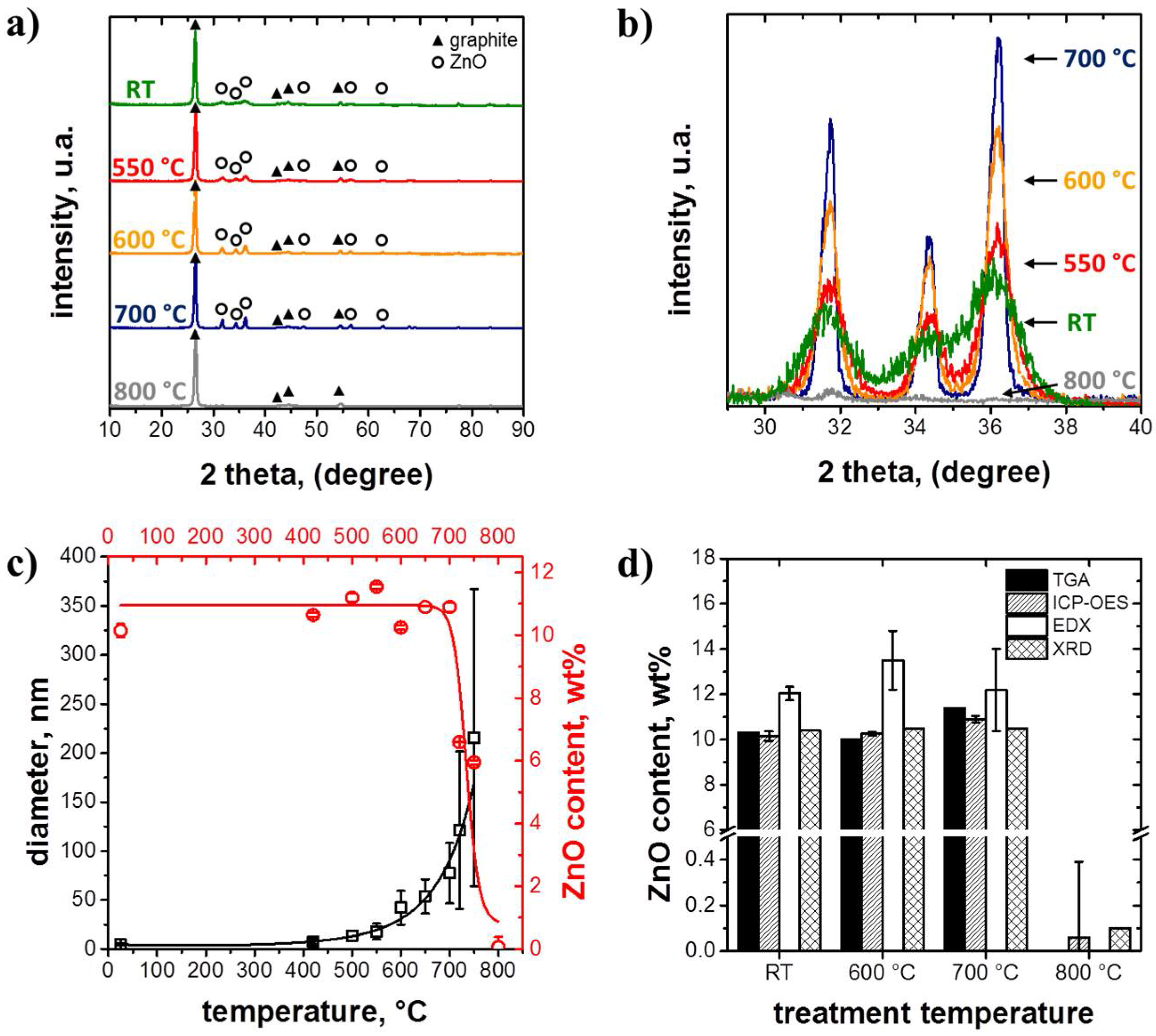
The XRD patterns of initial ZnO@EG composites (abbreviated with RT) and thermally treated ZnO@EG composites at different temperatures are shown in Figure 2a,b. The diffraction reflexes of EG in the XRD pattern are indexed with black triangles. EG exhibits four intensive diffraction reflexes at 2θ = 26.4°, 42.3°, 44.5°, and 50.6° corresponding to the (002), (100), (101), and (004) reflections of graphite (ICDD, PDF No. 00-056-0159). The characteristic graphitic reflex clearly appears at 2θ = 26.4° [37].
The ZnO@EG composites do not display the diffraction reflexes of graphite only, but also further diffraction reflexes located at 2θ = 31.7°, 34.3°, 36.1°, 47.4°, 56.5°, and 62.7°, attributed to (100), (002), (101), (102), (110), and (103) reflections of Wurtzite hexagonal structured ZnO (ICDD, PDF No. 04-008-8198), respectively. They are represented by the open circles in Figure 2a. The broadening of the ZnO diffraction reflexes in the pattern of the initial ZnO@EG composites indicates the low crystallinity of the nano-sized ZnO particles due to the absence of any long-range order [38]. After thermal treatment, the three main ZnO reflexes (100), (101), and (002) sharpen with increasing temperature, confirming that the average ZnO crystallite size and the crystallinity are significantly increased (Figure 2b). Nevertheless, the XRD pattern of ZnO@EG-800 °C composites shows the absence of the pronounced ZnO reflexes. Furthermore, the XRD patterns reveal no additional phases, confirming the high purity of ZnO@EG composites, and no changes of the basic structure, even after the thermal post-treatment processes.
In order to estimate the amount of ZnO in the composite after thermal treatments at different temperatures, inductively coupled plasma optical emission spectrometry (ICP-OES) was carried out. Figure 2c reveals a constant ZnO amount on the EG sheets up to 700 °C, followed by an abrupt decrease of the ZnO content at ≥720 °C, accompanied by an increase of the ZnO particle sizes. In order to confirm the ZnO content of the composites during the thermal post-treatment, TGA, EDX and XRD were applied (Figure 2d). All methods show a similar ZnO content. For all samples, EDX measurements show slightly higher values due to the local limitations of this method. However, ZnO particles cannot be detected on the EG sheets after a thermal treatment at 800 °C. The corresponding SEM images (Figure 3) support these findings and provide a deeper insight into the ZnO@EG composites after thermal post-treatment at different temperatures, i.e., 600 °C (Figure 3a), 700 °C (Figure 3b), and 800 °C (Figure 3c). The thermal treated ZnO@EG composites show, on the one hand, increasing ZnO particles size with increasing temperature and, on the other hand, an exfoliated graphite without ZnO NP coverage after thermal treatment at 800 °C (Figure 3c).
We attribute this to a carbothermal reduction of ZnO to Zn according to Equations (4) and (5) [39,40,41].
ZnO   +   C     Zn   +   CO
ZnO   +   CO     Zn   +   CO 2
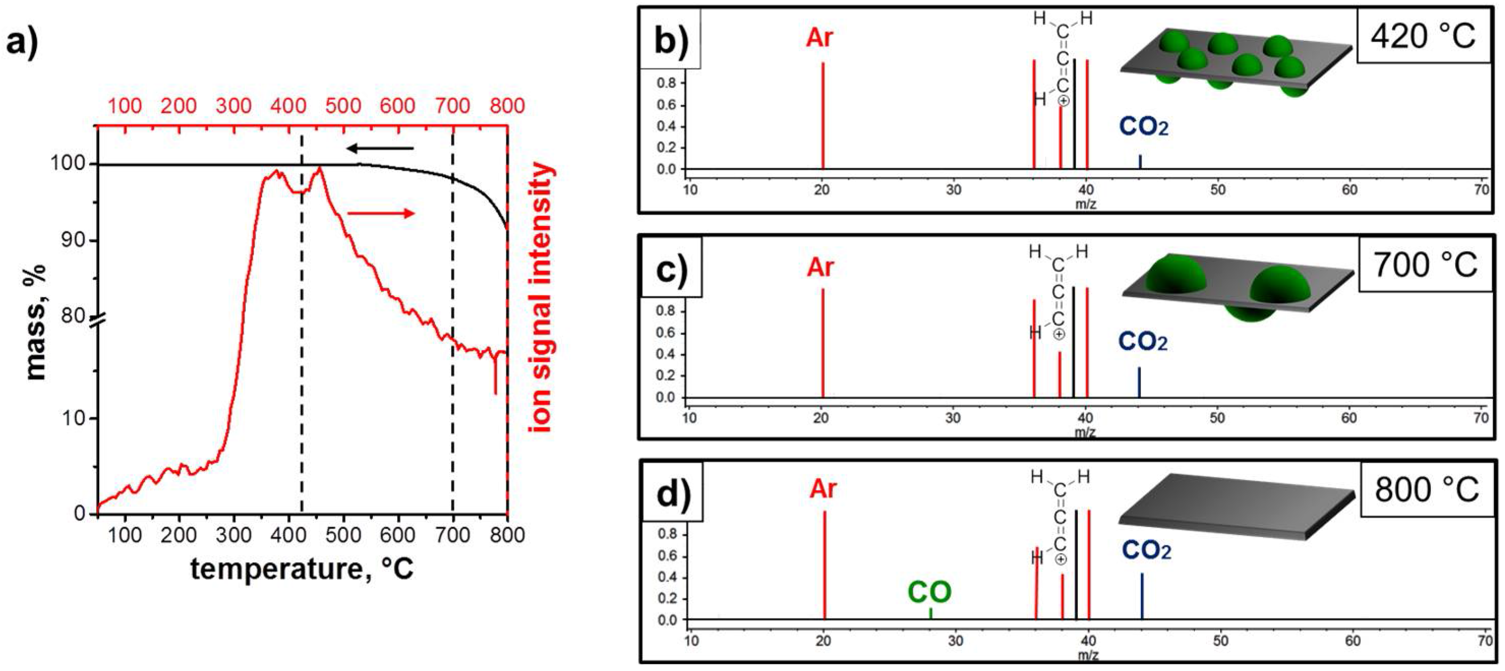
The corresponding STA-MS analyses, which were conducted from 30 °C to 800 °C in argon, support these findings and provide a deeper insight into the combustion process of the initial ZnO@EG composites (Figure 4a). N2 as carrier gas would not have been appropriate due to the overlap of the signals of N2 and CO in the MS. The ion signal exhibiting a pronounced intensity at about 420 °C is assigned to CO2 (m/z 44) and indicates the ZnO reduction according to Equation (5) (Figure 4b). The reduction of ZnO to Zn continues up to 700 °C (Figure 4c). The CO signal (m/z 28) appears first at 800 °C. It indicates the combustion of carbon (Figure 4d). Thus, the remaining almost 90 wt% at 800 °C are attributed to graphite, while the loss of ca. 10 wt% demonstrates a good correlation with the initial amount of adsorbed ZnO NPs. However, up to a temperature of 800 °C, a Zn signal at 65 m/z (as it is expected when Zn evaporates) was not detected, presumably due to the condensation of gaseous Zn at cold parts in front of the detector. The m/z 39 signal may be an indication for the hydrocarbon residues resulting from either solvent or defects in the graphite structure. Widespread peaks indicating Ar appear at 40 m/z (Ar+), 20 m/z (Ar2+) and 36 m/z (36Ar isotope). There is also a peak at 38 m/z assigned to the third stable isotope of argon (38Ar isotope) [42,43].
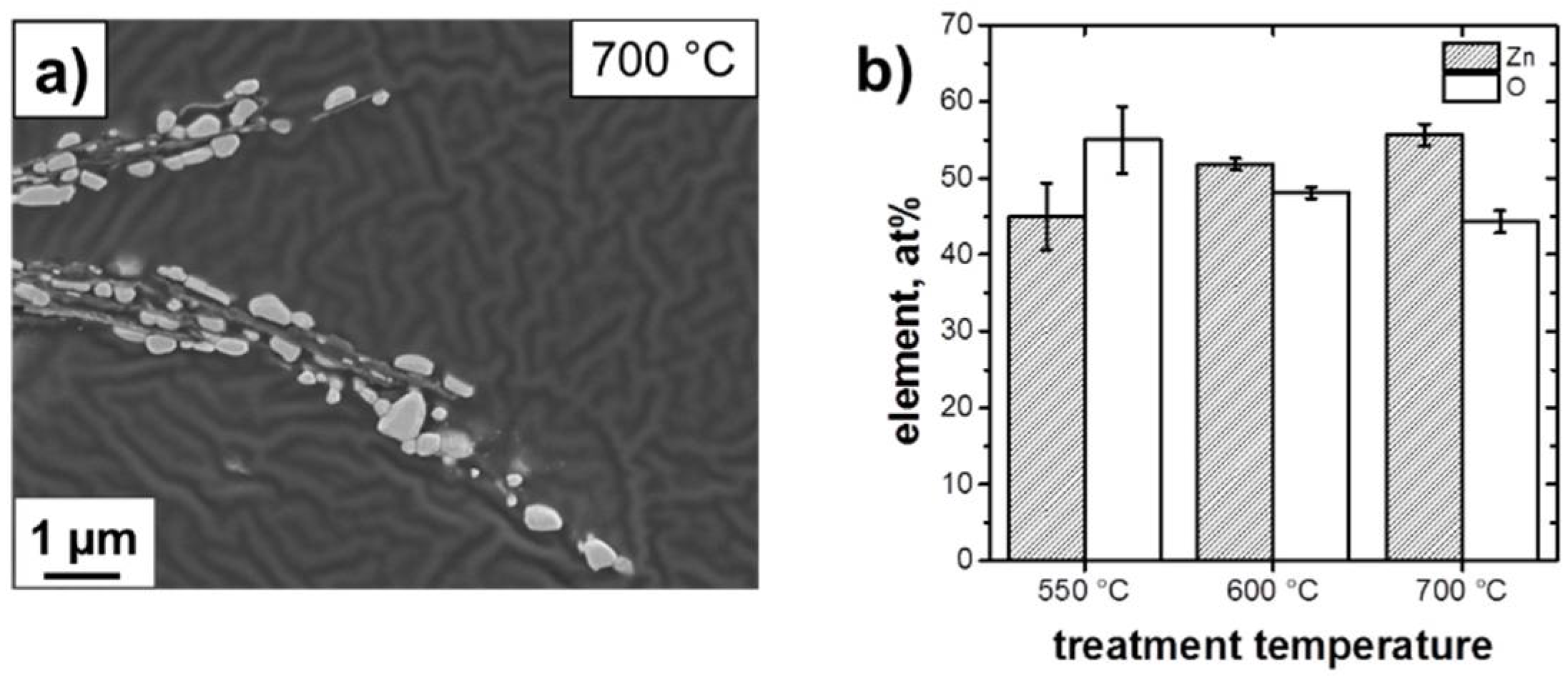
The carbothermal reduction during the thermal process should provide a lack of oxygen in the ZnO crystals. In order to prove this assumption, cross sections of thermally treated ZnO@EG composites were investigated by EDX to determine the zinc and oxygen amount in the ZnO crystals. It is obvious from the SEM cross section of ZnO@EG-700 °C composites that a layered structure is formed, consisting of alternating arrangement of ZnO particles and EG sheets (Figure 5a). It is evident that the ZnO particles (white particles) are sandwiched between the EG sheets (black sheets). The “wavy” signal background may stem from the embedding material consisting of EpoFix Resin and EpoFix Hardener (25:3).
The larger particles (treatment temperature ≥ 550 °C) facilitate a quantitative characterization of the ZnO stoichiometry due to the absence of the C signal originating from EG sheets (Figure 5b). The ZnO particles of ZnO@EG-550 °C composites show a higher amount of oxygen compared to the amount of zinc. In contrast, the ZnO@EG-600 °C composites show a lack of oxygen supporting the assumption of carbothermal reduction. The amount of oxygen decreases with increasing temperature caused by ongoing carbothermal reduction.

3.2. Electrochemical Performance

The increase of the Zn-content in the ZnO particles (which can also be written as ZnO1−x expressing the formation of oxygen vacancies in ZnO) is accompanied by the formation a donor level between the valence and conduction band and therefore by an increased density of conduction electrons [44,45,46]. This should lead to an increased electrical conductivity of the electrodes, with positive effects on the electrochemical behavior. However, the increase of the particle size leads to longer diffusion paths for Li+ ions insertion [21,47].
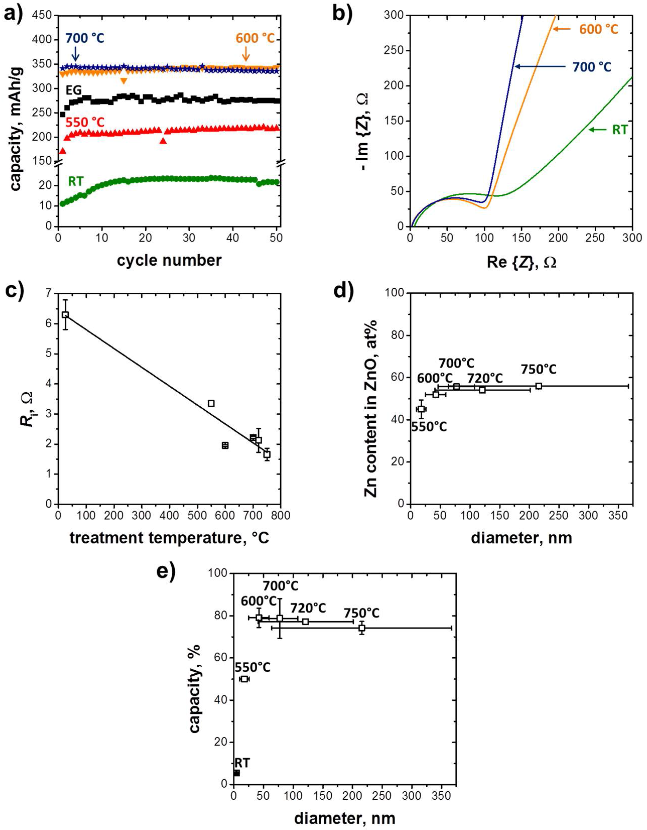
These composites are electrochemically investigated by galvanostatic measurements. Figure 6a compares the cycle performance of EG and ZnO@EG composites before and after the thermal treatments. The capacity of the initial ZnO@EG composites is very low with only 21.7 mAh/g after the 50th cycle, which is below the threshold of initial EG with a value of 274.6 mAh/g. As obvious from Figure 6a, the capacity of ZnO@EG-550 °C composites (218 mAh/g) is much higher compared to the initial ZnO@EG composites, whereas the capacity value of pure EG has still not been achieved. Only if the initial ZnO@EG composites are thermal treated above 600 °C, a higher capacity occurs. The ZnO@EG-600 °C composites show the best cycle performance among the four tested composites. A capacity of 343.5 mAh/g is maintained after the 50th cycle, which is a significant improvement of +25.1% compared to the initial EG substrate.
The enhanced electrochemical performance of thermally treated ZnO@EG composites may be attributed to their increased conductivity. The electrochemical conductivity of the ZnO@EG composite anodes is measured via EIS to confirm the relationship between the increased Zn stoichiometry in the ZnO particles and the enhanced electrochemical performance. Figure 6b shows Nyquist plots (plots in the complex plane) of initial ZnO@EG composites and of composites that were thermally treated at 600 °C and 700 °C. The plot consists of semicircles in the high frequency range that is presumably related to the charge transfer resistance and a straight line in the low frequency range that may reflect the Li+ transport in the electrolyte. The intercept on the Re{Z} axis at high frequencies can be considered as the internal resistance (Ri). Obviously, the diameter of the semicircle for initial ZnO@EG composites is larger than that of the thermally treated ZnO@EG composites, confirming the facilitated electron transport and of thermally treated composites [24]. The internal resistance Ri of initial ZnO@EG composites is (6.3 ± 0.5) Ω , while the thermally treated composites show a decrease of Ri down to (1.7 ± 0.2) Ω with increasing temperature (Figure 6c). The increased electrical conductivity of the electrodes can be attributed to the reduction of the ZnO particles, indicating an important effect on the improved capacity utilization of the composites.
Figure 6d shows the relationship between the Zn stoichiometry in the ZnO particles for different particle sizes. The achieved capacity behaves similarly for different particle sizes (Figure 6e). For better comparison, the capacity is indicated in % due to the slightly different ZnO amounts within the composites (Figure 2d). Therefore, 100% indicate the theoretical capacity of each ZnO@EG composite. It is shown that the increase of the Zn stoichiometry in the ZnO (or the increase of oxygen vacancies in ZnO that lead to increased electronic conduction) particles runs analogously to the course of the capacity, whereas the ZnO particle size does not seem to influence the capacity.
One may ask why the electrochemical performance of samples treated at 600 °C and 700 °C are so similar (Figure 6a). A possible explanation for this behavior could be the similar physical properties of both samples. They exhibit comparable internal resistances (Figure 6c) and an increased loss of oxygen in the ZnO particles was found (Figure 5b). Nevertheless, the larger particles size of 700 °C sample negatively affects the stability of electrochemical performance. The thermal treated composite at 700 °C shows a capacity fading during electrochemical cycling.
It should be noticed that the capacities of the composites are not yet satisfactory due to the initial low capacity and rate performance (Figure S1) of the used substrate. By transferring the presented concept to other types of graphite offering a higher initial capacity, the electrochemical performance can be further improved.
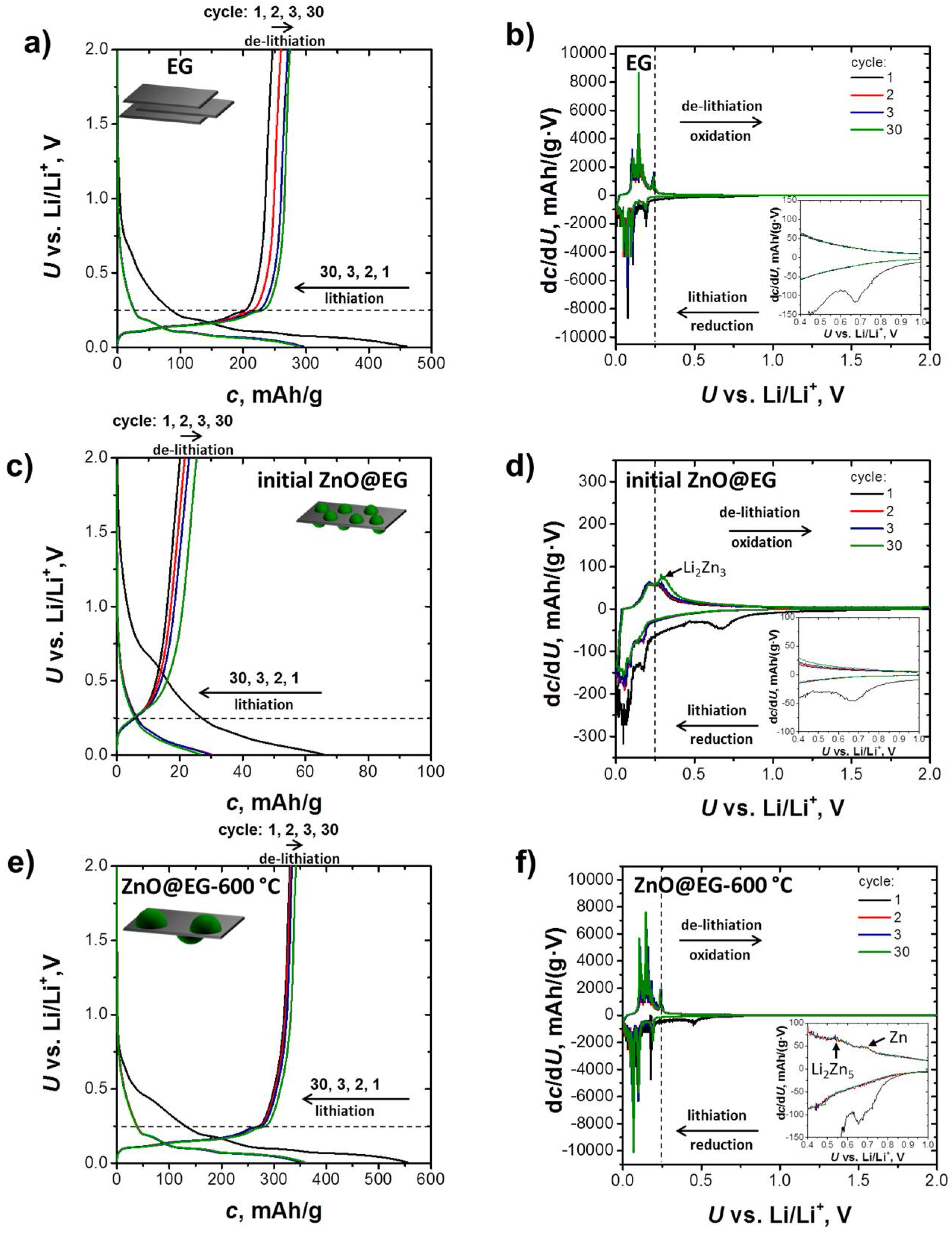
Galvanostatic discharge/charge curves of anode materials provide a deeper insight into the lithiation/de-lithiation process and help to better understand the reason for the poor electrochemical performance of the initial ZnO@EG composites. Figure 7 presents galvanostatic discharge (Li+ ions intercalation) and charge (Li+ ions de-intercalation) curves of EG, initial ZnO@EG and ZnO@EG-600 °C composites measured between 0.05 V and 2 V at 0.05 C-rate for the 1st, the 2nd, the 3rd, and the 30th cycle.
Figure 7a shows a typical graphite profile containing long plateaus below 0.25 V indicating Li+ ions intercalation and de-intercalation into the substrate [48]. During the lithiation, Li+ ions intercalate stepwise into the interlayer space of graphite, forming graphite intercalation compounds [49]. The plateaus located at 0.20 V, 0.11 V and 0.08 V indicate the Li+ ion intercalation steps into the graphite [50]. In addition, the short plateau at approximately 0.7 V reveals electrolyte decomposition caused by the irreversible formation of an SEI layer in the first charge process [51]. After the first cycle, the slopes and the curves are similar in shape indicating a good reversibility of the redox processes. The staging behavior becomes clearer in the differential specific capacity plots (dc/dU, Figure 7b), which has been directly derived from the discharge/charge curves by differentiation. It is worth noting that the plateaus in the voltage curves coincide with the peaks in the dc/dU-profiles. The reduction peaks show the Li+ ion intercalation steps into the graphite, whereas the oxidation peaks reveal the de-lithiation of graphite.
Figure 7c shows the galvanostatic discharge/charge curves of the initial ZnO@EG composites. Compared with the EG electrode, it is obvious that the initial ZnO@EG composites exhibit shorter plateaus as well as lower discharge and charge capacities. Additional information regarding the mechanism of the lithiation/de-lithiation process are revealed by the dc/dU-curves (Figure 7d). In the first cathodic scan, there is a broad peak in the range between 0.6 V and 0.8 V. We attribute it to the first electrochemical process of the composite, which contains the SEI layer formation and the reduction of ZnO to Zn (Equation (1)). The potentials of these reactions are very close, thus only one broad peak is detected. The same occurs for Li+ ion intercalation into the graphite and the formation of the LiZn alloy. However, the cathodic peak at 0.05 V is attributed to Li+ ion intercalation into the substrate, whereas the cathodic peak at 0.1 V indicates the formation of the final LiZn alloy stage according to Equation (3). In the first anodic scan, only two peaks at 0.21 V and 0.27 V are detected. They indicate the partial de-lithiation of EG and the de-alloying of ZnLi to the next Li2Zn3 intermediate stage. The absence of peaks at 0.66 V and approximately 1.4 V indicates the incomplete de-alloying process of ZnLi to Zn and the irreversible ZnO reduction to Zn and Li2O matrix. The irreversible reaction of some metal oxides to metal and the inactive Li2O matrix is already well known [52].
In summary, this may lead to the following picture: During electrochemical cycling, Li+ ions react irreversibly with ZnO reducing ZnO to Zn and Li2O matrix, then Li+ ions alloys further with Zn. The electrochemical active species such as Zn and EG are partially involved in the reaction with Li+ ions. The low electrical conductivity of the composite (Figure 6c) involves kinetic inhibition making it impossible for Zn to pass through all alloying stages with Li+. Hence, the reversible cycling occurs only between ZnLi and Li2Zn3 stages.
Peaks indicating the lithiation/de-lithiation process with graphite are either missing or are not as pronounced as in the case of EG. This implies that ZnO NPs adsorption takes place on the EG surface as well as on the EG edges preventing Li+ ion insertion into the graphite layers and resulting in low capacity utilization. This seems to be the reason for the poor electrochemical performance of the initial ZnO@EG composites. Figure 8a shows a schematic illustration for the Li+ ion insertion in the initial ZnO@EG composites according to the above-mentioned findings.
Compared with the initial ZnO@EG composite electrode, it is obvious that the ZnO@EG-600 °C composites exhibit longer plateaus, higher discharge and charge capacities (Figure 7e), as well as pronounced cathodic/anodic peaks (Figure 7f). Furthermore, two additional anodic peaks appear at 0.53 V (Li2Zn5) and 0.67 V (Zn) indicating the reversible de-alloying process of ZnLi to Zn. After the 1st cycle, the curves become almost identical in terms of shape and peak position indicating a reversible intercalation of the Li+ ions into the composite.
ZnO@EG-600 °C composites exhibit better electrochemical performance than the initial ZnO@EG composites due to the better electrical conductivity (Figure 6c) caused by the carbothermal reduction during the thermal post-treatment. The reduction changes the stoichiometry leading to an increased number of oxygen vacancies (Figure 5b) and to a higher electrical conductivity (Figure 6b) making it possible for Zn to pass through all alloying stages with Li+ ions (LixZny), whereas the ZnO reduction is still irreversible. It is known from literature that the present Li2O matrix acts as a “glue” to keep the alloying particles together and to reduce the volume change within the particles [52,53]. Hence, in the present work, both Li2O matrix and EG contribute to improved cycle stability.
The thermal treatment introduces growing ZnO NPs on the EG sheets. Consequently, the ZnO particles do not block the paths for Li+ ion intercalation inside the graphite layers. The accessibility of Li+ ions into the EG is confirmed by the sharp and pronounced peaks below 0.25 V. Thus, two electrochemical active species, namely Zn and EG, are completely involved in the reaction with the Li+ ions (Figure 8b) providing an enhanced capacity of over 25% as compared to the pure EG anode.

4. Conclusions

We introduced a simple method to form uniformly dispersed ZnO particles with controllable particle size on EG. Both composite formation and subsequent thermal treatment are characterized by high yield, simplicity, scalability, and the absence of hazardous chemicals. Thermal treatment of initial ZnO@EG composites affected the composite in terms of morphology, crystallinity, and conductivity, while the ZnO content remained unchanged up to 700 °C. Crystallinity and average particle size of ZnO as well as the conductivity of the composites increased with the annealing temperature. The increase of conductivity is achieved by the carbothermal reduction leading to an increased Zn stoichiometry in the ZnO crystals or an increased number of oxygen vacancies, both leading to a higher electrical conductivity.
The electrochemical characterization of the initial ZnO@EG composites reveals a low capacity in spite of the small ZnO particle size of around 5 nm. The reason for the poor electrochemical performance of the composites is the low electrical conductivity of the electrode, preventing the reversible formation of all ZnxLiy alloying stages. Furthermore, ZnO nano-sized particles prevent the Li+ ion intercalation into graphite due to its adsorption behavior on the surface as well as on the edges of EG.
Furthermore, we present a concept for the enhancement of electrochemical performance, which can be applied for similarly structures composites. It has been shown that thermally treated ZnO@EG composites with a certain electrical conductivity exhibit enhanced electrochemical performance in spite of the larger particle size (up to 80 nm) associated by longer diffusion paths for Li+ ions. Consequently, the ZnO@EG-600 °C composite shows both improved capacity and cycling stability compared to the initial ZnO@EG composites and even to EG, respectively. The improvement is also attributed to graphite and the irreversible formation of a Li2O matrix acting as a buffer to alleviate the large volume changes and to prevent the aggregation of ZnO NPs during the lithiation/de-lithiation process.
The results clearly exhibit higher capacity of over 25% of ZnO@EG-600 °C composites compared to the initial substrates indicating a potential application of ZnO@EG-600 °C composite as anode for lithium ion batteries.

Supplementary Materials

The following are available online at https://www.mdpi.com/2313-0105/4/2/24/s1.

Author Contributions

O.I. designed and performed the experiments as well analyzed the results and wrote the manuscript. S.H., O.S., M.W.-P. and R.M. provided the guidance. S.H., O.S., R.M. helped in manuscript preparation. R.M. contributed to scientific discussion and edited the manuscript.

Acknowledgments

The authors would like to thank Jasmin Bleisteiner for SEM, Ingrid Otto for STA-MS, Dominik Doleschal for TG, Michael Ringl for ICP-OES and Margit Fuchs for XRD measurements.

Conflicts of Interest

The authors and the institutes where the work has been carried out declare that there are no conflicts of interest regarding the publication of this article.

References

  1. Loeffler, N.; Bresser, D.; Passerini, S.; Copley, M. Secondary lithium-ion battery anodes: From first commercial batteries to recent research activities addressing the challenges in rechargeable lithium-ion battery technologies. Johns. Matthey Technol. Rev. 2015, 59, 34–44. [Google Scholar] [CrossRef]
  2. Yang, C.C.; Hung, Y.W.; Lue, S.J. The carbon additive effect on electrochemical performance of LiFe0.5Mn0.5PO4/C composites by a simple solid-state method for lithium ion batteries. Batteries 2016, 2, 18. [Google Scholar] [CrossRef]
  3. Tarascon, J.M.; Armand, M. Issues and challenges facing rechargeable lithium batteries. Nature 2001, 414, 359–367. [Google Scholar] [PubMed]
  4. Hsieh, C.T.; Lin, C.Y.; Chen, Y.F.; Lin, J.S. Synthesis of ZnO@Graphene composites as anode materials for lithium ion batteries. Electrochim. Acta 2013, 111, 359–365. [Google Scholar] [CrossRef]
  5. Singh, M.; Kaiser, J.; Hahn, H. Effect of porosity on the thick electrodes for high energy density lithium ion batteries for stationary applications. Batteries 2016, 2, 35. [Google Scholar] [CrossRef]
  6. Tatsumi, K.; Iwashita, N.; Sakaebe, H.; Shioyama, H.; Higuchi, S.; Mabuchi, A.; Fujimoto, H. The influence of the graphitic structure on the electrochemical characteristics for the anode of secondary lithium batteries. J. Electrochem. Soc. 1995, 142, 716–720. [Google Scholar]
  7. Sun, X.; Zhou, C.G.; Xie, M.; Sun, H.T.; Hu, T.; Lu, F.Y.; Scott, S.M.; George, S.M.; Lian, J. Synthesis of ZnO quantum dot/graphene nanocomposites by atomic layer deposition with high lithium storage capacity. J. Mater. Chem. A 2014, 2, 7319–7326. [Google Scholar] [CrossRef]
  8. Zhou, G.M.; Wang, D.W.; Li, F.; Zhang, L.L.; Li, N.; Wu, Z.S.; Wen, L.; Lu, G.Q.; Cheng, H.M. Graphene-wrapped Fe3O4 anode material with improved reversible capacity and cyclic stability for lithium ion batteries. Chem. Mat. 2010, 22, 5306–5313. [Google Scholar] [CrossRef]
  9. Wu, Z.S.; Ren, W.C.; Wen, L.; Gao, L.B.; Zhao, J.P.; Chen, Z.P.; Zhou, G.M.; Li, F.; Cheng, H.M. Graphene anchored with Co3O4 nanoparticles as anode of lithium ion batteries with enhanced reversible capacity and cyclic performance. ACS Nano 2010, 4, 3187–3194. [Google Scholar] [CrossRef] [PubMed]
  10. Bresser, D.; Paillard, E.; Niehoff, P.; Krueger, S.; Mueller, F.; Winter, M.; Passerini, S. Challenges of “Going Nano”: Enhanced electrochemical performance of cobalt oxide nanoparticles by carbothermal reduction and in situ carbon coating. ChemPhysChem 2014, 15, 2177–2185. [Google Scholar] [CrossRef] [PubMed]
  11. Xu, Y.; Yi, R.; Yuan, B.; Wu, X.F.; Dunwell, M.; Lin, Q.L.; Fei, L.; Deng, S.G.; Andersen, P.; Wang, D.H.; et al. High capacity MoO2/Graphite oxide composite anode for lithium-ion batteries. J. Phys. Chem. Lett. 2012, 3, 309–314. [Google Scholar] [CrossRef] [PubMed]
  12. Yao, J.; Shen, X.P.; Wang, B.; Liu, H.K.; Wang, G.X. In situ chemical synthesis of SnO2-graphene nanocomposite as anode materials for lithium-ion batteries. Electrochem. Commun. 2009, 11, 1849–1852. [Google Scholar] [CrossRef]
  13. Chen, Y.C.; Chen, J.M.; Huang, Y.H.; Lee, Y.R.; Shih, H.C. Size effect of tin oxide nanoparticles on high capacity lithium battery anode materials. Surf. Coat. Technol. 2007, 202, 1313–1318. [Google Scholar] [CrossRef]
  14. Zou, Y.Q.; Wang, Y. NiO nanosheets grown on graphene nanosheets as superior anode materials for Li-ion batteries. Nanoscale 2011, 3, 2615–2620. [Google Scholar] [CrossRef] [PubMed]
  15. Wang, B.; Wu, X.L.; Shu, C.Y.; Guo, Y.G.; Wang, C.R. Synthesis of CuO/graphene nanocomposite as a high-performance anode material for lithium-ion batteries. J. Mater. Chem. 2010, 20, 10661–10664. [Google Scholar] [CrossRef]
  16. Zhang, J.; Gu, P.; Xu, J.; Xue, H.G.; Pang, H. High performance of electrochemical lithium storage batteries: ZnO-based nanomaterials for lithium-ion and lithium-sulfur batteries. Nanoscale 2016, 8, 18578–18595. [Google Scholar] [CrossRef] [PubMed]
  17. Besenhard, C.D.; Besenhard, J.O. Handbook of Battery Materials; Wiley-VCH: Weinheim, Germany, 2011. [Google Scholar]
  18. Belliard, F.; Irvine, J.T.S. Electrochemical performance of ball-milled ZnO-SnO2 systems as anodes in lithium-ion battery. J. Power Sources 2001, 97–98, 219–222. [Google Scholar] [CrossRef]
  19. Quartarone, E.; Dall’Asta, V.; Resmini, A.; Tealdi, C.; Tredici, I.G.; Tamburini, U.A.; Mustarelli, P. Graphite-coated ZnO nanosheets as high-capacity, highly stable, and binder-free anodes for lithium-ion batteries. J. Power Sources 2016, 320, 314–321. [Google Scholar] [CrossRef]
  20. Guo, R.; Yue, W.B.; An, Y.M.; Ren, Y.; Yan, X. Graphene-encapsulated porous carbon-ZnO composites as high-performance anode materials for Li-ion batteries. Electrochim. Acta 2014, 135, 161–167. [Google Scholar] [CrossRef]
  21. Zhao, L.; Gao, M.M.; Yue, W.B.; Jiang, Y.; Wang, Y.; Ren, Y.; Hu, F.Q. Sandwich-structured graphene-Fe3O4@Carbon nanocomposites for high-performance lithium-ion batteries. ACS Appl. Mater. Interfaces 2015, 7, 9709–9715. [Google Scholar] [CrossRef] [PubMed]
  22. Stoller, M.D.; Park, S.J.; Zhu, Y.W.; An, J.H.; Ruoff, R.S. Graphene-based ultracapacitors. Nano Lett. 2008, 8, 3498–3502. [Google Scholar] [CrossRef] [PubMed]
  23. Zhu, Y.W.; Murali, S.; Cai, W.W.; Li, X.S.; Suk, J.W.; Potts, J.R.; Ruoff, R.S. Graphene and graphene oxide: Synthesis, properties, and applications. Adv. Mater. 2010, 22, 3906–3924. [Google Scholar] [CrossRef] [PubMed]
  24. Fang, H.M.; Zhao, L.; Yue, W.B.; Wang, Y.; Jiang, Y.; Zhang, Y. Facile and large-scale preparation of sandwich-structured graphene-metal oxide composites as anode materials for Li-ion batteries. Electrochim. Acta 2015, 186, 397–403. [Google Scholar] [CrossRef]
  25. Yoon, Y.S.; Jee, S.H.; Lee, S.H.; Nam, S.C. Nano Si-coated graphite composite anode synthesized by semi-mass production ball milling for lithium secondary batteries. Surf. Coat. Technol. 2011, 206, 553–558. [Google Scholar] [CrossRef]
  26. Song, W.T.; Xie, J.; Liu, S.Y.; Zheng, Y.X.; Cao, G.S.; Zhu, T.J.; Zhao, X.B. Graphene decorated with ZnO nanocrystals with improved electrochemical properties prepared by a facile in situ hydrothermal route. Int. J. Electrochem. Sci. 2012, 7, 2164–2174. [Google Scholar]
  27. Su, Q.M.; Dong, Z.M.; Zhang, J.; Du, G.H.; Xu, B.S. Visualizing the electrochemical reaction of ZnO nanoparticles with lithium by in situ TEM: Two reaction modes are revealed. Nanotechnology 2013, 24. [Google Scholar] [CrossRef] [PubMed]
  28. Bourlinos, A.B.; Gournis, D.; Petridis, D.; Szabo, T.; Szeri, A.; Dekany, I. Graphite oxide: Chemical reduction to graphite and surface modification with primary aliphatic amines and amino acids. Langmuir 2003, 19, 6050–6055. [Google Scholar] [CrossRef]
  29. Gilje, S.; Han, S.; Wang, M.; Wang, K.L.; Kaner, R.B. A chemical route to graphene for device applications. Nano Lett. 2007, 7, 3394–3398. [Google Scholar] [CrossRef] [PubMed]
  30. Simón, M.; Benítez, A.; Caballero, A.; Morales, J.; Vargas, O. Untreated natural graphite as a graphene source for high-performance li-ion batteries. Batteries 2018, 4, 13. [Google Scholar] [CrossRef]
  31. Wu, J.L.; Shen, X.P.; Jiang, L.; Wang, K.; Chen, K.M. Solvothermal synthesis and characterization of sandwich-like graphene/ZnO nanocomposites. Appl. Surf. Sci. 2010, 256, 2826–2830. [Google Scholar] [CrossRef]
  32. Kim, T.; Kim, H.; Han, J.-M.; Kim, J. ZnO-embedded N-doped porous carbon nanocomposite as a superior anode material for lithium-ion batteries. Electrochim. Acta 2017, 253, 190–199. [Google Scholar] [CrossRef]
  33. Isakin, O.; Schneider, R.; Ringl, M.; Struck, O.; Gerdes, T.; Willert-Porada, M.; Moos, R. High-yield synthesis of ZnO nanoparticles homogeneously coated on exfoliated graphite and simplified method to determine the surface coverage. Surf. Coat. Technol. 2017, 325, 445–453. [Google Scholar] [CrossRef]
  34. Isakin, O.; Hiltl, S.; Schneider, R.; Bleisteiner, J.; Struck, O.; Schindler, K.; Willert-Porada, M.; Moos, R. Ultrasound-assisted one-pot syntheses of ZnO nanoparticles that are homogeneously adsorbed on exfoliated graphite and a simplified method to determine the graphite layer thickness in such composites. J. Mater. Sci. 2018, 53, 6586–6601. [Google Scholar] [CrossRef]
  35. Paek, S.M.; Yoo, E.; Honma, I. Enhanced cyclic performance and lithium storage capacity of SnO2/Graphene nanoporous electrodes with three-dimensionally delaminated flexible structure. Nano Lett. 2009, 9, 72–75. [Google Scholar] [CrossRef] [PubMed]
  36. Rai, A.K.; Thi, T.V.; Paul, B.J.; Kim, J. Synthesis of nano-sized ZnCo2O4 anchored with graphene nanosheets as an anode material for secondary lithium ion batteries. Electrochim. Acta 2014, 146, 577–584. [Google Scholar] [CrossRef]
  37. Pierson, H.O. Handbook of Carbon, Graphite, Diamond and Fullerenes—Properties, Processing and Applications; Noyes Publications: Park Ridge, NJ, USA, 1993. [Google Scholar]
  38. Sankapal, B.R.; Gajare, H.B.; Karade, S.S.; Salunkhe, R.R.; Dubal, D.P. Zinc oxide encapsulated carbon nanotube thin films for energy storage applications. Electrochim. Acta 2016, 192, 377–384. [Google Scholar] [CrossRef]
  39. Gottstein, G.; Winning, M.; Friedrich, B. Metalle; Wiley-VCH: Weinheim, Germany, 2006. [Google Scholar]
  40. Hong, L.; Sohn, H.Y.; Sano, M. Kinetics of carbothermic reduction of magnesia and zinc oxide by thermogravimetric analysis technique. Scand. J. Metall. 2003, 32, 171–176. [Google Scholar] [CrossRef]
  41. Chen, H.K. Kinetic study on the carbothermic reduction of zinc oxide. Scand. J. Metall. 2001, 30, 292–296. [Google Scholar] [CrossRef]
  42. Contreras, C.S.; Salama, F. Laborarory investigations of polycyclic aromatic hydrocarbon formation and distrubution in the circumstellar outflows of carbon stars. Astrophys. J. Suppl. Ser. 2013. [Google Scholar] [CrossRef]
  43. Stein, S.E. Mass Spectra in NIST Chemistry WebBook; NIST Standard Reference Database Number 69; Linstrom, P.J., Mallard, W.G., Eds.; National Institute of Standards and Technology: Gaithersburg, MD, USA, 2012. Available online: http://webbook.nist.gov/cgi/cbook.cgi?Formula=Ar&NoIon=on&Units=SI&cMS=on (accessed on 7 January 2018).
  44. Zhang, C.; Geng, X.; Li, J.; Luo, Y.; Lu, P. Role of oxygen vacancy in tuning of optical, electrical and NO2 sensingproperties of ZnO1−x coatings at room temperature. Sens. Actuator B Chem. 2017, 248, 886–893. [Google Scholar] [CrossRef]
  45. Ou, G.; Li, D.K.; Pan, W.; Zhang, Q.H.; Xu, B.; Gu, L.; Nan, C.W.; Wu, H. Arc-melting to narrow the bandgap of oxide semiconductors. Adv. Mater. 2015, 27, 2589–2594. [Google Scholar] [CrossRef] [PubMed]
  46. Zhang, C.; Geng, X.; Liao, H.L.; Li, C.J.; Debliquy, M. Room-temperature nitrogen-dioxide sensors based on ZnO1−x coatings deposited by solution precursor plasma spray. Sens. Actuator B Chem. 2017, 242, 102–111. [Google Scholar] [CrossRef]
  47. Guo, Y.G.; Hu, J.S.; Wan, L.J. Nanostructured materials for electrochemical energy conversion and storage devices. Adv. Mater. 2008, 20, 2878–2887. [Google Scholar] [CrossRef]
  48. Aurbach, D.; Markovsky, B.; Weissman, I.; Levi, E.; Ein-Eli, Y. On the correlation between surface chemistry and performance of graphite negative electrodes for Li ion batteries. Electrochim. Acta 1999, 45, 67–86. [Google Scholar] [CrossRef]
  49. Ko, Y.; Cho, Y.G.; Song, H.K. Programming galvanostatic rates for fast-charging lithium ion batteries: A graphite case. RSC Adv. 2014, 4, 16545–16550. [Google Scholar] [CrossRef]
  50. Park, J.-K. Principles and Applications of Lithium Secondary Batteries; Wiley-VCH: Weinheim, Germany, 2012. [Google Scholar]
  51. Huang, X.H.; Xia, X.H.; Yuan, Y.F.; Zhou, F. Porous ZnO nanosheets grown on copper substrates as anodes for lithium ion batteries. Electrochim. Acta 2011, 56, 4960–4965. [Google Scholar] [CrossRef]
  52. Courtney, I.A.; Dahn, J.R. Electrochemical and in situ X-ray diffraction studies of the reaction of lithium with tin oxide composites. J. Electrochem. Soc. 1997, 144, 2045–2052. [Google Scholar] [CrossRef]
  53. Nitta, N.; Wu, F.X.; Lee, J.T.; Yushin, G. Li-ion battery materials: Present and future. Mater. Today 2015, 18, 252–264. [Google Scholar] [CrossRef]
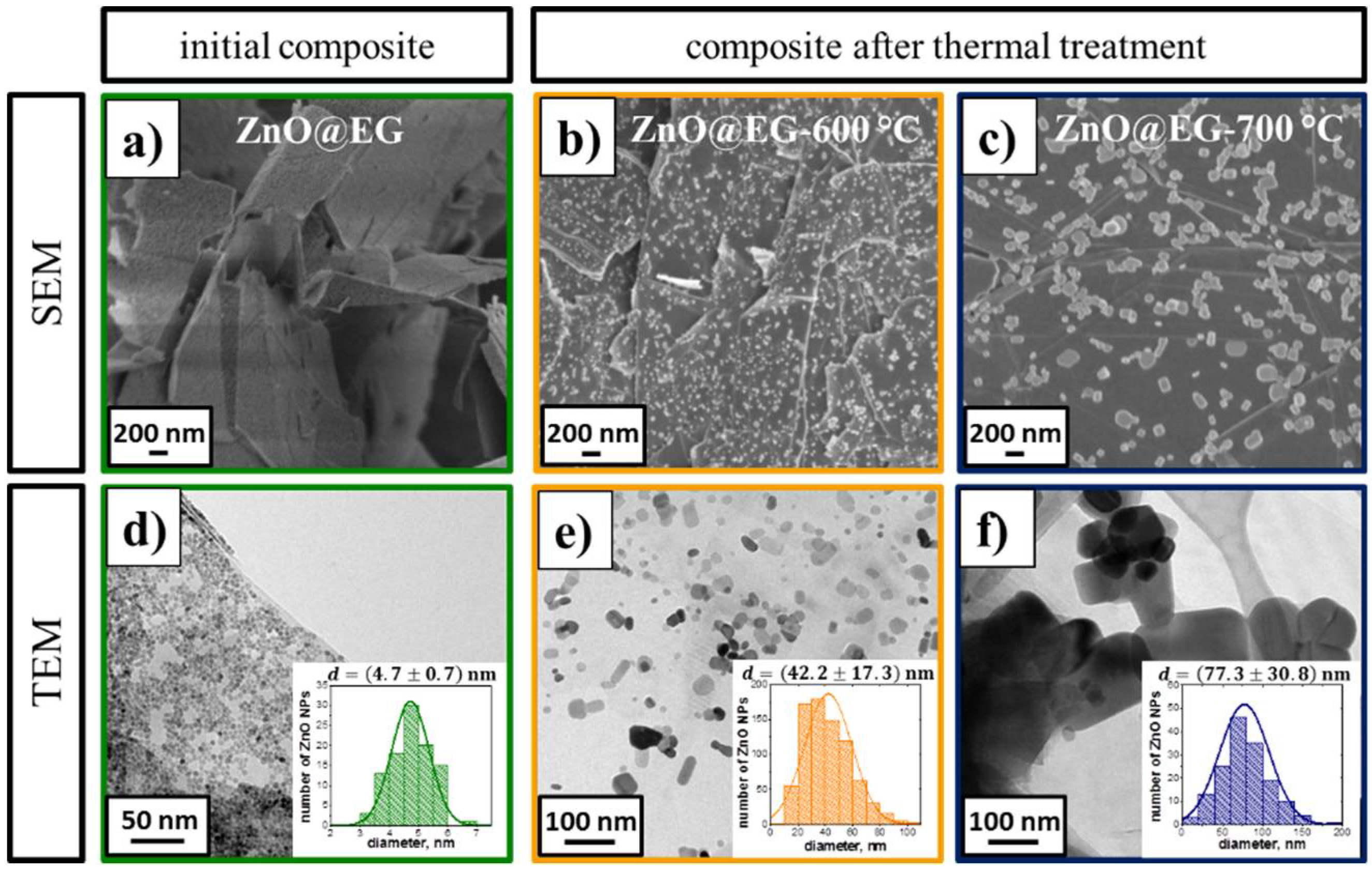
Figure 1. SEM and TEM images of (a,d) initial ZnO@EG composites and after thermal treatment at (b,e) 600 °C and (c,f) at 700 °C with corresponding histograms showing the size distributions (insets, obtained from at least 100 ZnO NPs. The colors of the frames correspond to the temperature of the thermal composite treatment.
Batteries 04 00024 g001
Figure 2. (a) XRD spectra before (RT) and after the thermal treatment of ZnO@EG composites at 550 °C, 600 °C 700 °C, and 800 °C with corresponding (b) magnification. (c) Particle growth during thermal post-treatment with corresponding ZnO content determined by ICP-OES and (d) TGA, EDX, and XRD.
Batteries 04 00024 g002
Figure 3. A series of SEM images of thermal treated ZnO@EG composites at (a) 600 °C; (b) 700 °C; and (c) 800 °C.
Batteries 04 00024 g003
Figure 4. (a) TG of initial ZnO@EG composites with corresponding ion signal intensity. MS spectrograms for thermally treated samples at (b) 420 °C; (c) 700 °C; and (d) 800 °C. The insets schematically illustrate the structural changes of the composite at the corresponding temperature. The dotted lines in (a) correlate with the temperatures in the MS spectrograms.
Batteries 04 00024 g004
Figure 5. (a) SEM cross section of as-prepared ZnO@EG-700 °C composite. (b) Content of elemental zinc and oxygen in ZnO particles after thermal post-treatment at different temperatures.
Batteries 04 00024 g005
Figure 6. (a) Cycle performance of EG, initial ZnO@EG composite (RT) and thermally treated composites at 550 °C, 600 °C, and 700 °C at 0.05 C-rate. (b) Electrochemical impedance spectra of EG, initial ZnO@EG composite prepared at room temperature (RT) and thermally treated composite at 600 °C and 700 °C before cycling. (c) Internal resistance as a function of the treatment temperature of ZnO@EG composites. (d) Plot of the Zn stoichiometry in the ZnO particles and (e) the capacity against the average ZnO particle size.
Batteries 04 00024 g006
Figure 7. Galvanostatic discharge (Li+ intercalation) and charge (Li+ de-intercalation) voltage profiles obtained from (a) EG and ZnO@EG composites (c) before and (e) after thermal treatment at 600 °C with the corresponding (b,d,f) plots of the differential specific capacity dc/dU vs. cell potential at 0.05 C-rate for 1st, 2nd, 3rd, and 30th cycle. The dotted black line is a guide for the eyes, showing the lithiation/de-lithiation process of EG occurring below 0.25 V.
Batteries 04 00024 g007
Figure 8. Schematic illustration of the lithiation process on the example of (a) initial ZnO@EG composites and (b) ZnO@EG-600 °C composites.
Batteries 04 00024 g008