Article

One-Step Electrospun LTO Anode for Flexible Li-Ion Batteries

1
School of Chemistry, Faculty of Exact Sciences, Tel Aviv University, Tel Aviv 69978, Israel
2
Jan Koum Center for Nanoscience and Nanotechnology, Tel Aviv University, Tel Aviv 6997801, Israel
3
The Center for Physics & Chemistry of Living Systems, Tel Aviv University, Tel Aviv 6997801, Israel
4
Department of Materials Science and Engineering, Tel Aviv University, Tel-Aviv 69978, Israel
*
Authors to whom correspondence should be addressed.
Batteries 2025, 11(11), 405; https://doi.org/10.3390/batteries11110405
Submission received: 15 October 2025 / Revised: 30 October 2025 / Accepted: 30 October 2025 / Published: 4 November 2025

Abstract

Fiber-based and fabric batteries signify a groundbreaking development in energy storage, allowing for the straightforward incorporation of power sources into wearable fabrics, intelligent apparel, and adaptable electronics. In this study, we introduce a novel strategy for one-step fabrication of a flexible lithium titanate oxide (Li4Ti5O12, LTO) anode directly on a copper current collector via electrospinning, eliminating the need for high-temperature post-processing. Based on our previous work with electrospun nanofiber cathodes and carbon-based current collector, we prepared the LTO electrode using polyethylene oxide (PEO) as a binder and carbon additives to enhance mechanical integrity and conductivity. LTO fiber mats detached from the current collector were found to endure multiple instances of bending, twisting, and folding without any structural damage. LTO/Li cells incorporating electrospun fiber LTO electrodes with 72 wt% active material loading deliver a high capacity of 170 mAh g−1 at 0.05 C. In addition, they demonstrate excellent cycling stability with a capacity loss of only 0.01% per cycle over 200 cycles and maintain a capacity of 160 mAh g−1 at 0.1 C. The scalability of the heat-treatment-free method for fabricating flexible LTO anodes, together with the improved mechanical durability and electrochemical performance, offers a promising route toward the development of next-generation flexible and wearable energy storage devices.

1. Introduction

Lithium-ion batteries (LIBs) have emerged as the leading energy storage solution over the past few decades, owing to their superior energy and power density [1,2]. With the increasing demand for compact, flexible, and mechanically robust micro-batteries, advanced electrode materials that can sustain high electrochemical performance while meeting the structural requirements of next-generation flexible and wearable energy storage systems are needed [3,4].
Recent research efforts have been strongly centered on developing flexible anodes for such applications. Various strategies that have yielded promising results in terms of capacity and cycling stability include the integration of binder-free composites such as Co9S8/rGO supported on a carbon cloth [5], graphene/Mn3O4 nanocomposite membrane [6], and conductive CNT-cellulose aerogels coated with Si via plasma-enhanced chemical vapor deposition [7]. While these systems show considerable potential, the majority require multi-step fabrication or post-processing under harsh conditions, such as high-temperature annealing or chemical vapor deposition, which hinder scalability and often compromise flexibility [8].
In our previous study, we demonstrated the feasibility of polymer-based LiFePO4 (LFP) cathode/current-collector micro-meshes with bi- and interlayered architectures fabricated via electrospinning, highlighting the method’s capability to produce flexible, mechanically resilient, and conductive electrodes suitable for integrated energy storage devices [9]. Building upon these findings, the present work extends this strategy to the anode side by developing flexible Li4Ti5O12 (LTO) fibers through a one-step electrospinning process.
Among various anode materials, “zero-strain” Li4Ti5O12 has attracted significant attention owing to its excellent safety, stable operating voltage (1.55 V vs. Li/Li+), which lies within the stability window of common electrolytes [10,11], and negligible volume change during cycling (~0.1%) [12,13,14]. These features suppress lithium dendrite growth and reduce the formation of an unstable solid-electrolyte interphase (SEI) layer, a common issue in graphite-based anodes [15,16]. Despite these advantages, the widespread practical application of LTO is hindered by its inherent kinetic limitations, including intrinsically low electronic conductivity and poor Li-ion diffusion ability. Spinel LTO is considered an insulator in its pristine state, due to the electronic configuration of Ti+4 [14,17]. While lithiation of Li7Ti5O12 can increase electronic conductivity significantly and mixed-valence states of Ti+3/Ti+4 at phase interfaces can enhance electron migration, the material still faces challenges in high-rate capability [14,17,18].
To address these limitations, 3D porous architectures and nanostructured LTO morphologies have been explored, because they enable enhanced ion transport, better electrolyte accessibility, and improved electrode kinetics [19,20,21,22]. Electrospinning has emerged as a versatile method to produce such architectures with fibrous, interconnected networks that offer both high surface area and mechanical flexibility [17]. Yet, in conventional electrospun LTO systems reported to date, high-temperature post-treatments (typically >600 °C) are routinely employed to decompose polymer carrier or crystallize LTO precursors to form the spinel phase [23,24,25,26,27,28]. These steps cause thermal shrinkage, fiber embrittlement, partial loss of active material or conductive additives, and demand complex thermal infrastructure, all of which undermine the potential for flexible device integration. A detailed comparison of electrospun anodes reported in the literature is provided in the Supplementary Materials (S1) [23,24,25,26,27,28,29,30,31,32].
In this study, we report a novel one-step electrospinning process for fabricating flexible LTO anode fibers that eliminates the need for post-thermal treatment. This approach preserves the as-spun fiber networks’ mechanical integrity, avoiding cracking and delamination associated with high temperature processing. To the best of our knowledge, this is the first demonstration of thermally untreated electrospun LTO mats with structural cohesion suitable for integration in flexible energy storage systems. Electrochemical measurements imply that these electrodes deliver capacities close to the theoretical value at low discharge rates, demonstrating their potential for stable low-power applications. At higher current densities, capacity limitations arise from diffusion-related constraints, revealing the trade-off between mechanical robustness and high-rate performance. Our method offers a scalable, energy-efficient pathway to flexible LTO anodes and highlights the design considerations needed for future development of high-performance, deformable lithium-ion batteries.

2. Materials and Methods

2.1. LTO Anode Preparation

The spinning suspension of the LTO anode was prepared by mixing carbon-coated LTO powder (LifePower C-T2, SUD-CHEMIE Clariant) with conductive additives, specifically carbon black (Super C65, C-Nergy, Imerys) and carboxyl-functionalized MWCNTs (US research nanomaterials, Inc.) in a solvent mixture of 4:1 (v/v) chloroform: N,N-dimethylformamide (DMF), followed by ultrasonication. Subsequently, Triton X-100 and Poly (ethylene oxide) (PEO) with an average molecular mass of 8 MDa (Sigma-Aldrich) were added to the mixture. The suspension was stirred for at least 24 h to achieve a uniform dispersion of the particles. To optimize the anode suspension formulation, various conditions, combinations of binders, solid loads, and surface-active agents were tested.
To fabricate the anode fibers, the prepared suspension was dispensed through a 25-gauge stainless-steel spinneret at a flow rate of 0.85 mL/h under an applied voltage of 3.5 kV between the needle and the collector. The needle-to-collector distance was 7 cm. The nanofibers were deposited onto copper foil mounted on a rotating grounded drum, resulting in porous electrode meshes. The copper substrate was later utilized as a current collector for the electrochemical characterization of the electrospun anode. To enhance the alignment and uniformity of the fibers, the drum was positioned horizontally on a moving X-stage, which facilitated back-and-forth motion during deposition. All experiments were conducted at room temperature under ambient conditions, with relative humidity maintained between 40% and 50%. The resulting electrospun meshes were vacuum-dried for 12 h to ensure complete solvent evaporation and subsequently were used for the assembly of lithium-ion coin cells.

2.2. Electrochemical Characterization of Electrospun LTO Anode

To evaluate the performance of the electrospun mats, CR2032 coin cell batteries were assembled and tested. The electrospun mat was punched into 12 mm diameter discs, which were then dried overnight at 60 °C under vacuum. The dried electrode discs were subsequently transferred to a glovebox filled with ultra-high-purity argon (content of O2 and H2O < 0.1 ppm). Coin cells were assembled using a single sheet of 19 mm diameter commercial polypropylene Celgard 2400 membrane as the separator and a 15 mm diameter Li metal counter electrode. A liquid electrolyte consisting of 0.3 M LiTFSI in PYR14TFSI ionic liquid (IL) electrolyte was used. To examine the reproducibility, at least three coin-cells were assembled and tested for each electrode. Galvanostatic charge/discharge cycling was performed at 30 °C within a voltage window of 1.2–2 V at rates ranging from 0.06 C to 1 C, using a BioLogic BSC-800 battery cycler, Seyssinet-Pariset, France.
Electrochemical impedance spectroscopy (EIS) measurements were performed using a BioLogic VMP3 potentiostat, at the cell’s open circuit voltage (OCV) state. The measurements were conducted over a frequency range of 10 kHz to 10 mHz using a 15 mV amplitude.
Cyclic voltammetry (CV) was conducted in a half-cell configuration to assess the performance of the electrospun LTO anode using an ionic liquid electrolyte. Measurements were carried out at a scan rate of 0.1 mVs−1, within the potential window of 1.0–3.0 V (vs. Li+/Li) at 30 °C.

2.3. Structural Characterization

The morphology of electrospun LTO composite fibers was analyzed using a high-resolution scanning electron microscope (HRSEM, Zeiss Gemini SEM 300, Oberkochen, Germany), equipped with an Energy-Dispersive X-ray Spectroscopy (EDS) detector (X-Flash 6/60, Bruker, Berlin, Germany), operating at an acceleration voltage of 2–5 kV. Additionally, a focused ion beam (FIB) integrated with an HRSEM (Helios 5 UC, ThermoFisher) and EDS detector was employed. A gallium ion FIB probe was used to mill the electrospun LTO electrode fibers and analyze their cross-sectional morphology.
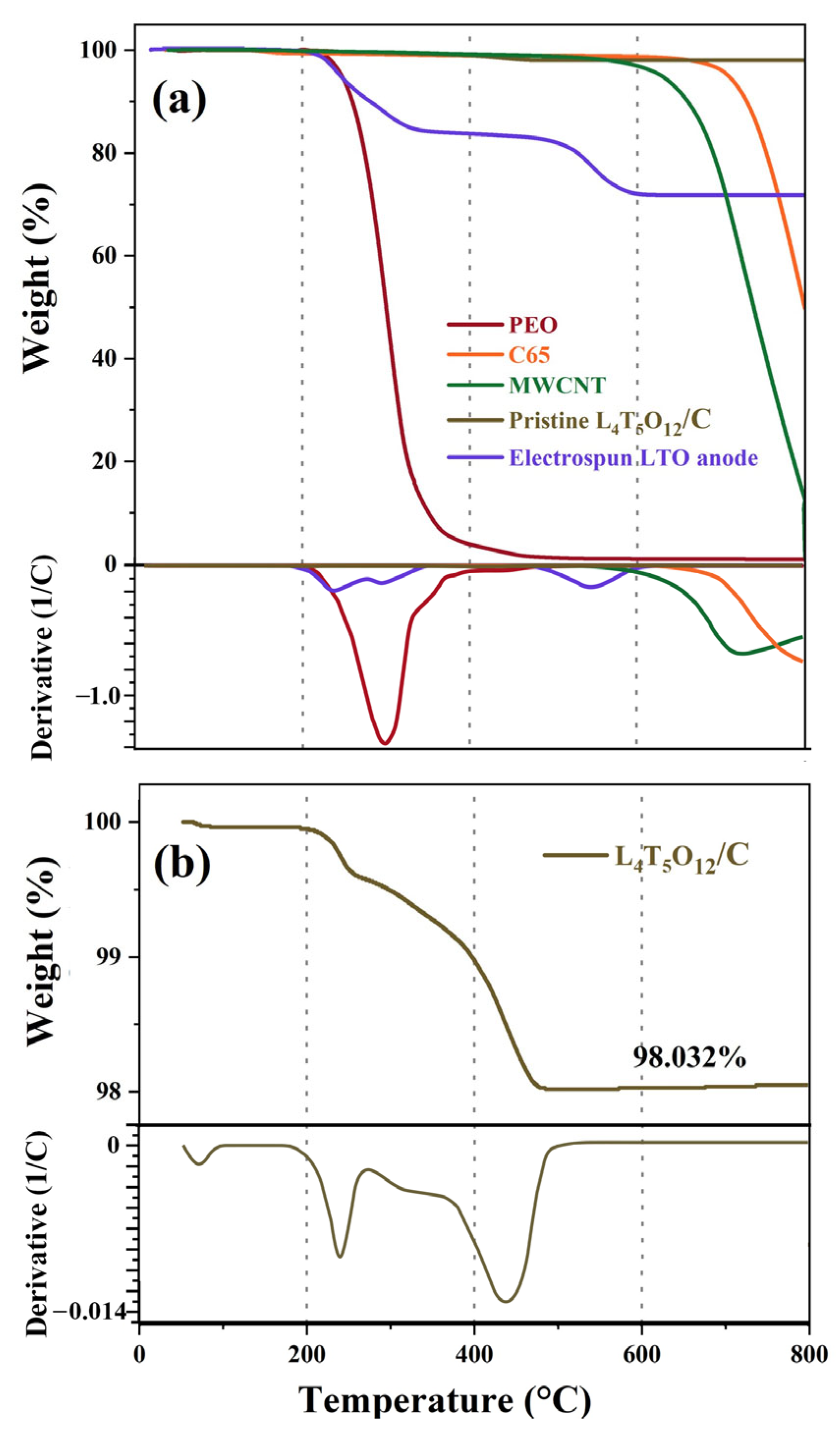
To determine the active material loading in the electrospun fibers, thermogravimetric analysis (TGA) measurements of pristine LTO, PEO (8 MDa), MWCNT, C65 and electrospun LTO fiber-meshes were performed. Each sample was loaded into an alumina crucible and heated under a dry purified air atmosphere to 800 °C at a rate of 20 °C min−1.

3. Results and Discussion

3.1. Morphology Characterization of Electrospun LTO Anode

The flexible LTO anode was fabricated via a single-step electrospinning process, in which LTO particles were directly incorporated into a spinning suspension with a PEO polymeric binder and conductive additives comprising carbon black (C65) and MWCNTs in a solvent mixture of 4:1 (v/v) CHCl3: DMF. The suspension was electrospun directly onto a copper current collector, forming a fibrous mat without the need for any post-thermal treatment. Eliminating this step allowed preserving the intrinsic flexibility of the as-spun network and avoiding thermal shrinkage and embrittlement typically observed in calcined fibers.
A schematic illustration of the fabrication process and the resulting fibrous LTO mat is shown in Figure 1.
To establish a reproducible one-step electrospinning of flexible LTO anodes, the suspension formulation and electrospinning parameters were systematically optimized. The goal was to maximize active material loading while ensuring a spinnable suspension that produces continuous, defect-free fibers with minimal bead formation and no mechanical breakage during processing. Controlling bead formation was crucial, as the presence of beads compromises fiber uniformity and disrupts the continuity of the conductive network within the electrode, thereby reducing its effective conductivity [33].
To ensure adequate electrical pathways within the fibrous network, C65 and MWCNTs were co-incorporated into the electrospinning solution. MWCNTs, owing to their high conductivity and large aspect ratio, enable the formation of a percolating conductive network at low loadings (typically below 1.0 wt%), while preserving the flexibility of the fibers [34,35,36]. PEO was selected as the polymeric binder due to its ability to form flexible, continuous fibers, its proven compatibility with a range of electrode materials, including LTO, and its widespread use in lithium battery systems [37,38], enabling the direct fabrication of mechanically robust electrodes without post-thermal treatment.
Following iterative optimization, the final suspension composition comprised 73 wt% LTO, 14 wt% PEO (8 MDa), 5 wt% C65 (CB) and 7 wt% MWCNT, with 1 wt% Triton-X surfactant to promote uniform dispersion of carbonaceous additives and prevent agglomeration [39]. This formulation yielded uniform, stable fibers with high active material loading and structural integrity, enabling their direct integration into deformable lithium-ion batteries without additional processing. Figure 2 presents a photograph of the free-standing LTO electrode, detached from the copper substrate for mechanical testing. The electrode maintains its structural integrity under various deformations, including bending, twisting, rolling, and folding, highlighting its excellent mechanical robustness.
With the optimized formulation and electrospinning parameters established, the resulting fibrous LTO mats were examined using SEM and TGA to evaluate fiber uniformity, active material distribution, and polymer content, as well as to verify that the one-step process yields structurally intact electrodes.
TGA (Figure 3) was performed on both the pristine components and the composite LTO fiber mat to determine active material loading. The profiles of the materials and their derivatives revealed that PEO undergoes complete decomposition at 450 °C, while C65 and MWCTs exhibit thermal stability up to 600 and 700 °C, respectively (Figure 3a), consistent with data reported in the literature [40,41,42]. Pristine carbon-coated LTO/C (Figure 3b) shows minimal weight loss across a wide temperature range, confirming its high thermal stability. Minor weight losses between 200–300 °C and 350–500 °C are attributed to carbon burn-off in ambient air, with a total carbon content of 1.97 wt% [43,44].
The TGA profile and its derivative for the electrospun LTO fibers (Figure 3a) display two major weight loss regions. The first occurred between 200 °C and 375 °C, corresponding to the decomposition of the polymeric binder. The second, (500–650 °C), is associated with the decomposition of carbon additives (MWCNT and C65) at lower temperatures than the pristine carbon additives. Based on the residual mass, the LTO loading in the electrospun fibers was calculated to be 72 wt%, which closely aligns with the LTO content in the initial jetting suspension mixture.
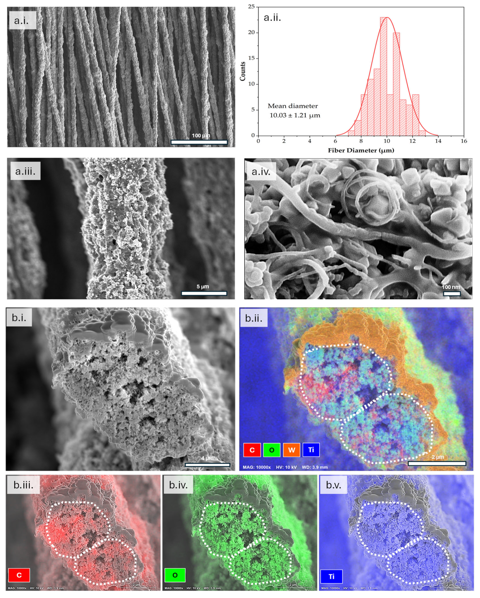
SEM examination (Figure 4) uncovered the morphological characteristics of the electrospun fibers. High-resolution SEM micrographs (Figure 4a) showed elongated, continuous, and bead-free fibers with an average diameter of 10.03 ± 1.21 µm, forming a porous, interconnected network that is expected to facilitate electrolyte infiltration and lithium-ion transport. To examine internal structure, a FIB was used to section the fibers, with a protective tungsten layer deposited before milling. Cross-sectional SEM micrographs (Figure 4b.i) revealed that LTO particles were uniformly embedded within a matrix of the polymer binder and the conductive additives.
Elemental mapping (Figure 4b.ii–v) confirmed the homogeneous distribution of titanium (Ti) and oxygen (O), indicative of LTO particles, alongside carbon-rich (C) regions corresponding to the presence of CB particles and MWCNTs. This intimate integration is expected to form a continuous conductive network, providing efficient electron pathways between the current collector and the LTO active material during electrochemical cycling.

3.2. Electrochemical Characterization

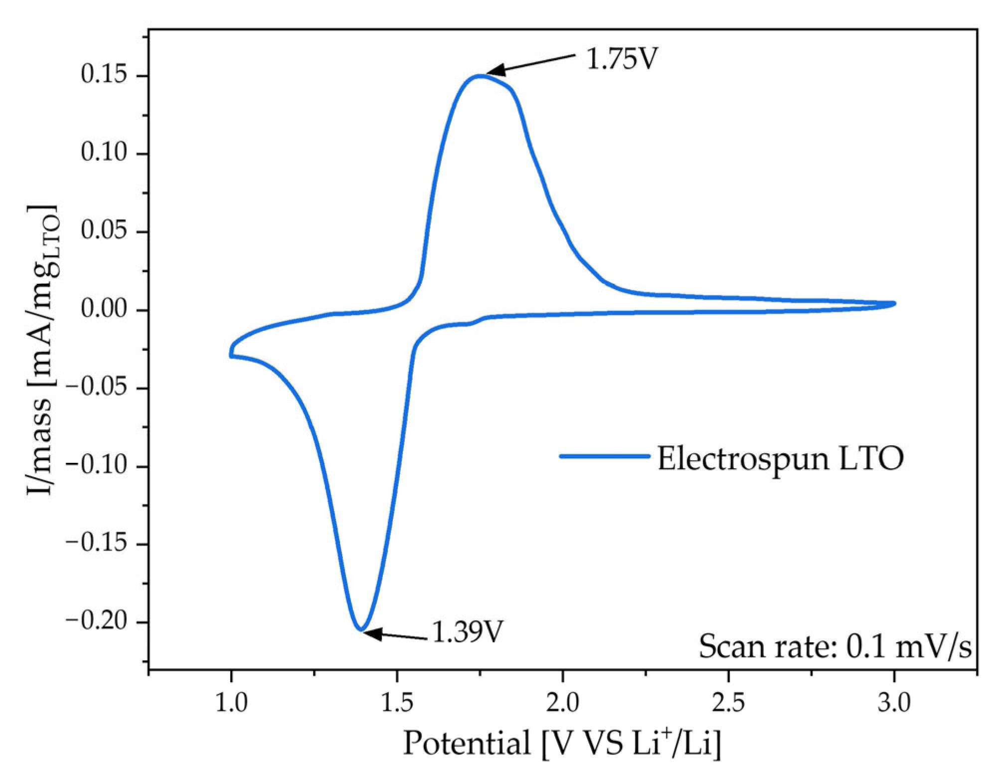
Figure 5 presents the CV profile of the electrospun LTO anode, recorded at a scan rate of 0.1 m Vs−1 within the potential range of 1.0–3.0 V (vs Li+/Li), using 70 µL of PYR14TFSI ionic liquid containing 0.3 M LiTFSI. The electrospun electrode exhibits two distinct redox peaks at 1.39 V and 1.75 V, corresponding to the lithiation and delithiation of the spinel LTO phase, respectively [45]. To maintain the electrode integrity, ionic liquid (IL) PYR14TFSI was used instead of conventional alkyl carbonate electrolytes, since the PEO binder dissolves in carbonate media [46].
Although ILs are often limited by high viscosity and a low Li+ transference number [47,48], they are highly compatible with PEO. Their weak interaction with the polymer prevents binder dissolution while simultaneously enabling Li+ coordination through the ether oxygens in PEO chains [49,50,51]. Combined with the porous morphology of the spun electrode, these synergistic effects promote local ionic conductivity and Li+ accessibility, resulting in sharper and more distinct redox peaks.
The electrochemical performance of the electrospun LTO fibers was evaluated in a Li half-cell configuration at room temperature, to assess their rate capability and cycling stability. The electrodes had an average active material loading of 1.26 mg LTO·cm−2 and were cycled between 1.2 and 2.0 V at identical charge/discharge rates, with current densities ranging from 0.06 to 1 C. Figure 6a presents the galvanostatic charge–discharge profiles at varying C-rates. At 0.06 C the profile displayed a discharge plateau at 1.547 V and a charge plateau at 1.583 V. These reactions involve the reduction of three Ti4+ ions to Ti3+ during the two-phase transition from spinel-LTO to rock-salt LTO, as described by the following reduction equation [13,52,53]:
Li4Ti5O12 + 3Li++3e ↔ Li7Ti5O12
The small polarization at low rate (ΔV = 15.7 mV) (Figure 6a, b) indicates efficient Li+ insertion/extraction pathways within the fibrous network, despite the absence of high-temperature post-treatment. Increasing the current density led to a progressive widening of the voltage gap to 25.3 mV (0.13 C), 117.5 mV (0.68 C), and 202.2 mV (1 C), reflecting growing kinetic limitations associated with restricted Li+ mobility at elevated rates. At higher rates, rapid Li+ consumption at the LTO surface, combined with limited ionic transport in the IL electrolyte, results in pronounced concentration polarization [18,47,48,54]. This leads to localized Li+ depletion (during discharge) or accumulation (during charge), leading to an increase in overpotential. Furthermore, the reformation of the electronically insulating Li4Ti5O12 phase during charge exacerbates overpotential under high current conditions [17].
Rate capability results (Figure 6c) show that at low rates, the untreated LTO fibers deliver a discharge capacity of 170 mAh g−1, corresponding to 97% of the theoretical capacity value of spinel LTO (175 mAh g−1). This value surpasses the typical capacities reported in the literature (~160 mAh g−1) [55,56], demonstrating that the electrospun microstructure supports near-complete lithiation at these rates. The electrodes exhibit excellent capacity retention up to 0.13 C, but the performance gradually declines at 0.68 C (129 mAh g−1) and 1 C (77 mAh g−1), where both ionic transport through the high-viscosity Pyr14TFSI-based electrolytes and solid-state Li+ diffusion in LTO are expected to be a limiting factor [18,48,57,58]. Upon returning to 0.13 C, the capacity recovered 95% of its initial value, confirming that the observed limitations are kinetic rather than structural, a key outcome for mechanically robust electrodes. The coulombic efficiency remained near 100% across all rates, with minor deviations at 1 C, attributed to electrolyte transport limitations and surface Li+ depletion at elevated current densities.
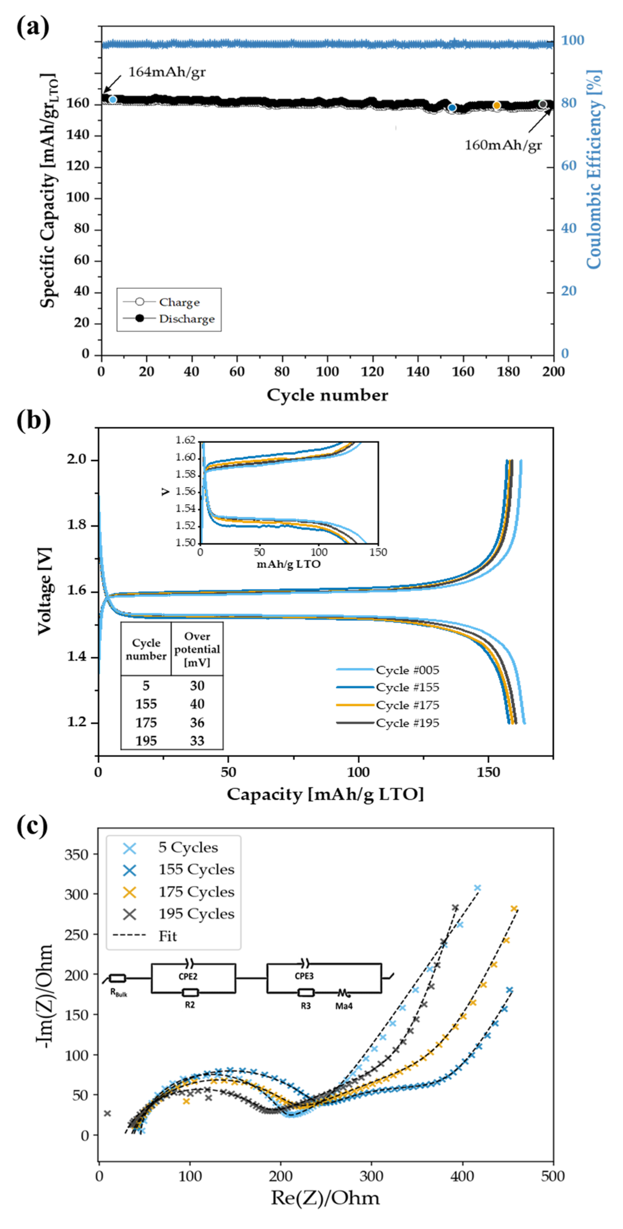
Cycling stability at 0.1 C (Figure 7a) demonstrated stable and high long-term performance, with 160 mAh g−1 retained after 200 cycles, corresponding to a negligible capacity loss of 0.01% per cycle and total capacity loss of 1.83%. The coulombic efficiency consistently remained close to 99.6%. This stability reflects both the intrinsic zero-strain property of LTO and the structural cohesion of the electrospun network, which remained intact. EIS measurements were performed at selected stages during the long-term cycling (Figure 7c). Measurements were first conducted after 5 cycles and then after 155 cycles to evaluate stability over extended operation. Beyond this point, EIS was recorded every 20 cycles. All spectra were collected after discharge, following a one-hour rest period to ensure relaxation.
The Nyquist plot (Figure 7c) and the corresponding fitting parameters (Table 1) reveal a dispersion factor (αd) consistently above 0.65, indicating that the low-frequency region cannot be accurately fitted using a conventional Warburg element. A classical Warburg response typically exhibits a slope of π/4 and a dispersion parameter of αd = 0.5, whereas the intermediate slopes detected here suggest a mixed reaction between a semi-infinite Warburg element and a finite-space Warburg (FSW) response, generally associated with porous electrode structure and limited ion diffusion [59,60]. To more accurately capture this non-ideal diffusion, a modified restricted diffusion element (Ma) was incorporated into the equivalent circuit model (Figure 7c, inset). This element, composed of a resistive component (Rd) in parallel with a constant phase element (Qd), accounts for geometry-limited, frequency-dependent diffusion and reproduces the depressed semicircle observed in the spectra. A detailed mathematical description of this model is provided in the Supplementary Materials (S2) [59,60,61,62,63].
Analysis of the impedance evolution highlights distinct trends during cycling. After 5 cycles, the cell exhibited low interfacial resistances and a moderate overpotential (30 mV, Figure 7b), reflecting efficient Li+ transport in the fresh electrode. By 155 cycles, both R2 and R3 had increased substantially, accompanied by a rise in overpotential to 40 mV, indicating the development of interfacial polarization and lower Li transport. While the mid-frequency arc (R2||Q2) is often attributed to the active electrode, in a two-electrode configuration it also reflects contributions from the Li electrode, where continuous plating/stripping promotes SEI thickening [64,65,66]. The simultaneous increase of R2 and R3 from cycle 5 to 155, together with the increased Q2 and depressed semicircle (αd > 0.7), supports the formation of a more resistive interphases, originating from both restructuring of the polymer-salt interphase on the electrospun LTO fibers and thickening of the SEI on Li. These interfacial processes jointly contribute to the polarization observed at mid-life cycling. With continued cycling to 175 and 195 cycles, both R2 and R3 partially decreased, accompanied by an increase in αd toward unity. This behavior suggests a stabilization and reorganization of the electrolyte/electrodes interfaces, possibly facilitated by the one-hour rest period before EIS measurements [67]. Concurrently, the decrease in bulk resistance (Rbulk), from 46 Ω after 5 cycles to 28 Ω after 195 cycles, indicates enhanced electrolyte penetration and improved electrode-electrolyte contact, which mitigates ohmic drop across the cell. These findings confirm that the dominant impedance evolution arises from dynamic interfacial processes, rather than intrinsic ohmic resistance.
Overall, these results highlight that the untreated electrospun LTO anode can deliver near-theoretical capacity at low-to-moderate rates, while maintaining stable cycling at moderate current densities. At high rates, performance is primarily constrained by Li+ transport kinetics rather than structural degradation, with the fibrous architecture and mechanical integrity remaining intact, features essential for flexible battery applications. This balance between structural flexibility and high-rate capability underscores the need for future designs to optimize the system, enabling improved electrochemical performance without compromising the advantages of the one-step fabrication process.
The PEO in the system serves not only as a mechanical binder but also as an ionic conductor through Li+ coordination with the ether oxygen sites. However, its partial crystallinity at room temperature is expected to limit chain mobility and can locally impede Li+ transport. Despite this, the optimized PEO content, together with MWCNT and carbon black additives, establishes continuous ionic and electronic pathways. This synergy enables efficient charge transfer while maintaining the fibrous mat’s flexibility and mechanical integrity, as evidenced by stable Coulombic efficiency, low interfacial resistance, and minimal polarization during cycling.
While the obtained areal mass loadings are relatively moderate, there is clear potential for improvement within the current fabrication framework. Increasing the active material loading by extending deposition time or stacking multiple fibrous layers could effectively boost capacity. However, excessive thickness may hinder ion transport and solvent evaporation, leading to structural inhomogeneity. Future efforts will therefore focus on tailoring fiber-mat density and porosity to enhance areal capacity while preserving both mechanical robustness and electrochemical stability.

4. Conclusions

An advanced flexible LTO anode was successfully fabricated via a one-step electrospinning technique, eliminating the need for high-temperature post-treatment. The incorporation of PEO binder with MWCNT and carbon black additives yielded a mechanically robust fibrous mat, capable of withstanding repeated bending, twisting, rolling, and folding without structural degradation. The fibrous architecture enabled a high specific capacity of 170 mAh g−1 at 0.06 C (97% of the theoretical value) and excellent long-term cycling stability, with 98.2% capacity retention and >99% coulombic efficiency after 200 cycles at 0.1 C. These results underscore the potential of electrospinning as a scalable and cost-effective strategy for producing flexible, high-performance anodes for next-generation energy storage systems. Further work will focus on enhancing rate capability through optimization of the fiber composition (reducing binder fraction while preserving electrical conductivity and mechanical stability) and exploring electrolyte-electrode interactions to improve Li+ transport. Importantly, coupling this flexible LTO anode with compatible cathode materials in full-cell configurations represents a critical step toward practical, fully flexible lithium-ion batteries for wearable and portable electronics.

Supplementary Materials

The following supporting information can be downloaded at https://www.mdpi.com/article/10.3390/batteries11110405/s1: (S1) Comparison of electrospun flexible LTO and other anode systems by processing temperature and rate performance. (S2) Detailed low-frequency impedance model equations.

Author Contributions

Conceptualization, E.E.M., D.G. and A.S.; methodology, E.E.M., D.G. and A.S.; formal analysis, E.E.M.; investigation, E.E.M., R.A. and N.K.; writing—original draft preparation, review and editing, E.E.M., D.G. and A.S.; supervision, D.G. and A.S. All authors have read and agreed to the published version of the manuscript.

Funding

A.S. thanks the Israel Science Foundation (grant no. 1682/22) and the Army Research Office (Grant Number W911NF-23–1–0257). The views and conclusions contained in this document are those of the authors and should not be interpreted as representing the official policies, either expressed or implied, of the Army Research Office or the U.S. Government. The U.S. Government is authorized to reproduce and distribute reprints for Government purposes, notwithstanding any copyright notation.

Data Availability Statement

The original contributions presented in this study are included in the article/Supplementary Materials. Further inquiries can be directed to the corresponding author(s).

Acknowledgments

The authors would like to thank the Gordon Center for Energy Studies, Tel Aviv University, for their generous support. The authors acknowledge the Chaoul Center for Nanoscale Systems of Tel Aviv University for the use of instruments and staff assistance, and the Mechanical Workshop for Research and Development, School of Chemistry, Tel Aviv University, for help in constructing the fabrication devices.

Conflicts of Interest

The authors declare no conflicts of interest.

Abbreviations

The following abbreviations are used in this manuscript:
LTOLithium Titanate Oxide
PEOPolyethylene Oxide
MWCNTMulti-Wall Carbon Nanotube
SEISolid Electrolyte Interphase
OCVOpen Circuit Voltage
EISElectrochemical Impedance Spectroscopy
(HR)SEM(High Resolution) Scanning Electron Microscope
CVCyclic Voltammetry
EDSEnergy Dispersive X-Ray Spectroscopy
TGAThermogravimetric Analysis

References

  1. Zhao, Y.; Pohl, O.; Bhatt, A.I.; Collis, G.E.; Mahon, P.J.; Rüther, T.; Hollenkamp, A.F. A Review on Battery Market Trends, Second-Life Reuse, and Recycling. Sustain. Chem. 2021, 2, 167–205. [Google Scholar] [CrossRef]
  2. Gao, Y.; Pan, Z.; Sun, J.; Liu, Z.; Wang, J. High-Energy Batteries: Beyond Lithium-Ion and Their Long Road to Commercialisation; Springer: Singapore, 2022; Volume 14. [Google Scholar]
  3. Fan, X.; Liu, B.; Ding, J.; Deng, Y.; Han, X.; Hu, W.; Zhong, C. Flexible and Wearable Power Sources for Next—Generation Wearable Electronics. Batter. Supercaps 2020, 3, 1262–1274. [Google Scholar] [CrossRef]
  4. Zhang, Q.; Soham, D.; Lian, Z.; Wan, J. Advances in wearable energy storage and harvesting systems. Med-X 2025, 3, 3. [Google Scholar] [CrossRef]
  5. Wang, N.; Hou, W.; Chang, Y.; Song, H.; Li, H.; Li, Y.; Han, G. Binder-free hydrogen storage composite Co9S8/rGO: A prospective anode for flexible energy storage device with high energy density. Electrochim. Acta 2020, 354, 136734. [Google Scholar] [CrossRef]
  6. Wang, J.G.; Jin, D.; Zhou, R.; Li, X.; Liu, X.R.; Shen, C.; Xie, K.; Li, B.; Kang, F.; Wei, B. Highly Flexible Graphene/Mn3O4 Nanocomposite Membrane as Advanced Anodes for Li-Ion Batteries. ACS Nano 2016, 10, 6227–6234. [Google Scholar] [CrossRef]
  7. Hu, L.; Liu, N.; Eskilsson, M.; Zheng, G.; McDonough, J.; Wågberg, L.; Cui, Y. Silicon-conductive nanopaper for Li-ion batteries. Nano Energy 2013, 2, 138–145. [Google Scholar] [CrossRef]
  8. Wang, X.; Lu, X.; Liu, B.; Chen, D.; Tong, Y.; Shen, G. Flexible energy-storage devices: Design consideration and recent progress. Adv. Mater. 2014, 26, 4763–4782. [Google Scholar] [CrossRef]
  9. Mados, E.; Atar, I.; Gratz, Y.; Israeli, M.; Kondrova, O.; Fourman, V.; Sherman, D.; Golodnitsky, D.; Sitt, A. Polymer-based LFP cathode/current collector microfiber-meshes with bi- and interlayered architectures for Li-ion battery. J. Power Sources 2024, 603, 234397. [Google Scholar] [CrossRef]
  10. Opra, D.P.; Gnedenkov, S.V.; Sokolov, A.A.; Minaev, A.N.; Kuryavyi, V.G.; Sinebryukhov, S.L. Facile synthesis of nanostructured transition metal oxides as electrodes for Li-ion batteries. AIP Conf. Proc. 2017, 1874, 397–402. [Google Scholar]
  11. Kavan, L.; Procházka, J.; Spitler, T.M.; Kalbáč, M.; Zukalová, M.; Drezen, T.; Grätzel, M. Li Insertion into Li4Ti5O12 (Spinel). J. Electrochem. Soc. 2003, 150, A1000. [Google Scholar] [CrossRef]
  12. Ronci, F.; Reale, P.; Scrosati, B.; Panero, S.; Rossi Albertini, V.; Perfetti, P.; Di Michiel, M.; Merino, J.M. High-resolution in-situ structural measurements of the Li4/3Ti5/3O4 “zero-strain” insertion material. J. Phys. Chem. B 2002, 106, 3082–3086. [Google Scholar] [CrossRef]
  13. Ohzuku, T.; Ueda, A.; Yamamoto, N. Zero—Strain Insertion Material of Li[Li1/3Ti5/3]O4 for Rechargeable Lithium Cells. J. Electrochem. Soc. 1995, 142, 1431–1435. [Google Scholar] [CrossRef]
  14. Yan, H.; Zhang, D.; Qilu; Duo, X.; Sheng, X. A review of spinel lithium titanate (Li4Ti5O12) as electrode material for advanced energy storage devices. Ceram. Int. 2021, 47, 5870–5895. [Google Scholar] [CrossRef]
  15. Asenbauer, J.; Eisenmann, T.; Kuenzel, M.; Kazzazi, A.; Chen, Z.; Bresser, D. The success story of graphite as a lithium-ion anode material-fundamentals, remaining challenges, and recent developments including silicon (oxide) composites. Sustain. Energy Fuels 2020, 4, 5387–5416. [Google Scholar] [CrossRef]
  16. Zaghib, K.; Dontigny, M.; Guerfi, A.; Charest, P.; Rodrigues, I.; Mauger, A.; Julien, C.M. Safe and fast-charging Li-ion battery with long shelf life for power applications. J. Power Sources 2011, 196, 3949–3954. [Google Scholar] [CrossRef]
  17. Wu, K.; Yang, J.; Qiu, X.Y.; Xu, J.M.; Zhang, Q.Q.; Jin, J.; Zhuang, Q.C. Study of spinel Li4Ti5O12electrode reaction mechanism byelectrochemical impedance spectroscopy. Electrochim. Acta 2013, 108, 841–851. [Google Scholar] [CrossRef]
  18. Vasileiadis, A.; de Klerk, N.J.J.; Smith, R.B.; Ganapathy, S.; Harks, P.P.R.M.L.; Bazant, M.Z.; Wagemaker, M. Toward Optimal Performance and In-Depth Understanding of Spinel Li4Ti5O12 Electrodes through Phase Field Modeling. Adv. Funct. Mater. 2018, 28, 1705992. [Google Scholar] [CrossRef]
  19. Park, S.K.; Copic, D.; Zhao, T.Z.; Rutkowska, A.; Wen, B.; Sanders, K.; He, R.; Kim, H.K.; De Volder, M. 3D Porous Cu-Composites for Stable Li-Metal Battery Anodes. ACS Nano 2023, 17, 14658–14666. [Google Scholar] [CrossRef]
  20. Patnaik, S.G.; Jadon, A.; Tran, C.C.H.; Estève, A.; Guay, D.; Pech, D. High Areal Capacity Porous Sn-Au Alloys with Long Cycle Life for Li-ion Microbatteries. Sci. Rep. 2020, 10, 10405. [Google Scholar] [CrossRef]
  21. Hu, L.; La Mantia, F.; Wu, H.; Xie, X.; McDonough, J.; Pasta, M.; Cui, Y. Lithium-ion textile batteries with large areal mass loading. Adv. Energy Mater. 2011, 1, 1012–1017. [Google Scholar] [CrossRef]
  22. Wang, A. Three-Dimensional Hierarchical Porous Electrode Structure for Improved Performance in Battery Applications. Int. J. High Sch. Res. 2022, 4, 1–5. [Google Scholar] [CrossRef]
  23. Lu, H.W.; Zeng, W.; Li, Y.S.; Fu, Z.W. Fabrication and electrochemical properties of three-dimensional net architectures of anatase TiO2 and spinel Li4Ti5O12 nanofibers. J. Power Sources 2007, 164, 874–879. [Google Scholar] [CrossRef]
  24. Xu, H.; Hu, X.; Luo, W.; Sun, Y.; Yang, Z.; Hu, C.; Huang, Y. Electrospun Conformal Li4Ti5O12/C Fibers for High-Rate Lithium-Ion Batteries. ChemElectroChem 2014, 1, 611–616. [Google Scholar] [CrossRef]
  25. Zhu, N.; Liu, W.; Xue, M.; Xie, Z.; Zhao, D.; Zhang, M.; Chen, J.; Cao, T. Graphene as a conductive additive to enhance the high-rate capabilities of electrospun Li4Ti5O12 for lithium-ion batteries. Electrochim. Acta 2010, 55, 5813–5818. [Google Scholar] [CrossRef]
  26. Sandhya, C.P.; John, B.; Gouri, C. Synthesis and electrochemical characterisation of electrospun lithium titanate ultrafine fibres. J. Mater. Sci. 2013, 48, 5827–5832. [Google Scholar] [CrossRef]
  27. Abureden, S.; Hassan, F.M.; Lui, G.; Ahn, W.; Sy, S.; Yu, A.; Chen, Z. Multigrain electrospun nickel doped lithium titanate nanofibers with high power lithium ion storage. J. Mater. Chem. A 2016, 4, 12638–12647. [Google Scholar] [CrossRef]
  28. Zhang, Z.; Deng, X.; Sunarso, J.; Cai, R.; Chu, S.; Miao, J.; Zhou, W.; Shao, Z. Two-Step Fabrication of Li4Ti5O12-Coated Carbon Nanofibers as a Flexible Film Electrode for High-Power Lithium-Ion Batteries. ChemElectroChem 2017, 4, 2286–2292. [Google Scholar] [CrossRef]
  29. Ji, L.; Zhang, X. Electrospun carbon nanofibers containing silicon particles as an energy-storage medium. Carbon 2009, 47, 3219–3226. [Google Scholar] [CrossRef]
  30. Self, E.C.; McRen, E.C.; Pintauro, P.N. High Performance Particle/Polymer Nanofiber Anodes for Li-ion Batteries using Electrospinning. ChemSusChem 2016, 9, 208–215. [Google Scholar] [CrossRef]
  31. Self, E.C.; Wycisk, R.; Pintauro, P.N. Electrospun titania-based fibers for high areal capacity Li-ion battery anodes. J. Power Sources. 2015, 282, 187–193. [Google Scholar] [CrossRef]
  32. Aravindan, V.; Suresh, P.; Sundaramurthy, J.; Ling, W.C.; Ramakrishna, S.; Madhavi, S. Electrospun NiO nanofibers as high performance anode material for Li-ion batteries. J. Power Sources 2013, 227, 284–290. [Google Scholar] [CrossRef]
  33. Nan, X.; Zhang, Y.; Shen, J.; Liang, R.; Wang, J.; Jia, L.; Yang, X.; Yu, W.; Zhang, Z. A Review of the Establishment of Effective Conductive Pathways of Conductive Polymer Composites and Advances in Electromagnetic Shielding. Polymers 2024, 16, 2539. [Google Scholar] [CrossRef]
  34. Li, J.; Ma, P.C.; Chow, W.S.; To, C.K.; Tang, B.Z.; Kim, J.K. Correlations between percolation threshold, dispersion state, and aspect ratio of carbon nanotubes. Adv. Funct. Mater. 2007, 17, 3207–3215. [Google Scholar] [CrossRef]
  35. Burmistrov, I.; Gorshkov, N.; Ilinykh, I.; Muratov, D.; Kolesnikov, E.; Anshin, S.; Mazov, I.; Issi, J.P.; Kusnezov, D. Improvement of carbon black based polymer composite electrical conductivity with additions of MWCNT. Compos. Sci. Technol. 2016, 129, 79–85. [Google Scholar] [CrossRef]
  36. Ma, P.C.; Liu, M.Y.; Zhang, H.; Wang, S.Q.; Wang, R.; Wang, K.; Wong, Y.K.; Tang, B.Z.; Hong, S.H.; Paik, K.W.; et al. Enhanced electrical conductivity of nanocomposites containing hybrid fillers of carbon nanotubes and carbon black. ACS Appl. Mater. Interfaces 2009, 1, 1090–1096. [Google Scholar] [CrossRef]
  37. Wen, B.R. Nanostructured Li4Ti5O12 as Anode Material for Lithium Ion Batteries. Master’s Thesis, Faculty of Science, The University of New South Wales, Kensington, NSW, Australia, 2012. [Google Scholar]
  38. Ragones, H.; Vinegrad, A.; Ardel, G.; Goor, M.; Kamir, Y.; Dorfman, M.M.; Gladkikh, A.; Golodnitsky, D. On the Road to a Multi-Coaxial-Cable Battery: Development of a Novel 3D-Printed Composite Solid Electrolyte. J. Electrochem. Soc. 2020, 167, 070503. [Google Scholar] [CrossRef]
  39. Li, Q.; Church, J.S.; Kafi, A.; Naebe, M.; Fox, B.L. An improved understanding of the dispersion of multi-walled carbon nanotubes in non-aqueous solvents. J. Nanopart. Res. 2014, 16, 2513. [Google Scholar] [CrossRef]
  40. Singh, N.K.; Verma, M.L.; Minakshi, M. PEO nanocomposite polymer electrolyte for solid state symmetric capacitors. Bull. Mater. Sci. 2015, 38, 1577–1588. [Google Scholar] [CrossRef]
  41. Freiberg, A.T.S.; Sicklinger, J.; Solchenbach, S.; Gasteiger, H.A. Li2CO3 decomposition in Li-ion batteries induced by the electrochemical oxidation of the electrolyte and of electrolyte impurities. Electrochim. Acta 2020, 346, 136271. [Google Scholar] [CrossRef]
  42. Mahajan, A.; Kingon, A.; Kukovecz, Á.; Konya, Z.; Vilarinho, P.M. Studies on the thermal decomposition of multiwall carbon nanotubes under different atmospheres. Mater. Lett. 2013, 90, 165–168. [Google Scholar] [CrossRef]
  43. Zhu, G.-N.; Wang, C.-X.; Xia, Y.-Y. A Comprehensive Study of Effects of Carbon Coating on Li4Ti5O12 Anode Material for Lithium-Ion Batteries. J. Electrochem. Soc. 2011, 158, A102. [Google Scholar] [CrossRef]
  44. Yuan, T.; Yu, X.; Cai, R.; Zhou, Y.; Shao, Z. Synthesis of pristine and carbon-coated Li4Ti5O12 and their low-temperature electrochemical performance. J. Power Sources 2010, 195, 4997–5004. [Google Scholar] [CrossRef]
  45. Agrawal, R.; Hao, Y.; Song, Y.; Chen, C.; Wang, C. Hybridization of lithium-ion batteries and electrochemical capacitors: Fabrication and challenges. Energy Harvest. Storage Mater. Devices Appl. VI 2015, 9493, 94930B. [Google Scholar]
  46. Appetecchi, G.B.; Aihara, Y.; Scrosati, B. Investigation of swelling phenomena in PEO-based polymer electrolytes: II. Chemical and electrochemical characterization. Solid State Ionics 2004, 170, 63–72. [Google Scholar] [CrossRef]
  47. Montanino, M.; Moreno, M.; Carewska, M.; Maresca, G.; Simonetti, E.; Lo Presti, R.; Alessandrini, F.; Appetecchi, G.B. Mixed organic compound-ionic liquid electrolytes for lithium battery electrolyte systems. J. Power Sources 2014, 269, 608–615. [Google Scholar] [CrossRef]
  48. Castiglione, F.; Ragg, E.; Mele, A.; Appetecchi, G.B.; Montanino, M.; Passerini, S. Molecular environment and enhanced diffusivity of Li+ ions in lithium-salt-doped ionic liquid electrolytes. J. Phys. Chem. Lett. 2011, 2, 153–157. [Google Scholar] [CrossRef]
  49. Diddens, D.; Heuer, A. Simulation study of the lithium ion transport mechanism in ternary polymer electrolytes: The critical role of the segmental mobility. J. Phys. Chem. B 2014, 118, 1113–1125. [Google Scholar] [CrossRef] [PubMed]
  50. An, Y.; Han, X.; Liu, Y.; Azhar, A.; Na, J.; Nanjundan, A.K.; Wang, S.; Yu, J.; Yamauchi, Y. Progress in Solid Polymer Electrolytes for Lithium-Ion Batteries and Beyond. Small 2022, 18, 1–36. [Google Scholar] [CrossRef]
  51. Guchok, O.; Ardel, G.; Keidar, T.D.; Nakar, H.; Ragones, H.; Kaplan, D.; Zheng, A.; Greenbaum, S.; Lounev, I.; Greenbaum, A.; et al. Understanding of the ion transport in blended TPU-PEO polymer electrolytes. J. Solid State Electrochem. 2025. [Google Scholar] [CrossRef]
  52. Zaghib, K.; Simoneau, M.; Armand, M.; Gauthier, M. Electrochemical study of Li4Ti5O12 as negative electrode for Li-ion polymer rechargeable batteries. J. Power Sources 1999, 81–82, 300–305. [Google Scholar] [CrossRef]
  53. Sun, X.; Radovanovic, P.V.; Cui, B. Advances in spinel Li4Ti5O12 anode materials for lithium-ion batteries. New J. Chem. 2015, 39, 38–63. [Google Scholar] [CrossRef]
  54. Kim, J.H.; Song, S.W.; Van Hoang, H.; Doh, C.H.; Kim, D.W. Study on the cycling performance of Li4Ti5O 12 electrode in the ionic liquid electrolytes containing an additive. Bull. Korean Chem. Soc. 2011, 32, 105–108. [Google Scholar] [CrossRef]
  55. Huynh, L.T.N.; Ha, C.T.D.; Nguyen, V.D.; Nguyen, D.Q.; Le, M.L.P.; Tran, V.M. Structure and Electrochemical Properties of Li4Ti5O12 Prepared via Low-Temperature Precipitation. J. Chem. 2019, 2019, 1727859. [Google Scholar] [CrossRef]
  56. Zaghib, K.; Armand, M.; Gauthier, M. Electrochemistry of Anodes in Solid—State Li—Ion Polymer Batteries. J. Electrochem. Soc. 1998, 145, 3135–3140. [Google Scholar] [CrossRef]
  57. Elia, G.A.; Ulissi, U.; Jeong, S.; Passerini, S.; Hassoun, J. Exceptional long-life performance of lithium-ion batteries using ionic liquid-based electrolytes. Energy Environ. Sci. 2016, 9, 3210–3220. [Google Scholar] [CrossRef]
  58. Ara, M.; Meng, T.; Nazri, G.-A.; Salley, S.O.; Simon Ng, K.Y. Ternary Imidazolium-Pyrrolidinium-Based Ionic Liquid Electrolytes for Rechargeable Li-O2 Batteries. J. Electrochem. Soc. 2014, 161, A1969–A1975. [Google Scholar] [CrossRef]
  59. Diard, J.-P.; Le Gorrec, B.; Montella, C. Diffusion Impedances. In Handbook of Electrochemical Impedance Spectroscopy; Electrical Circuits Containing CPEs, Bio-Logic: Seyssinet-Pariset, France, 2013. [Google Scholar]
  60. Cabanel, R.; Barral, G.; Diard, J.P.; Le Gorrec, B.; Montella, C. Determination of the diffusion coefficient of an inserted species by impedance spectroscopy: Application to the H/HxNb2O5 system. J. Appl. Electrochem. 1993, 23, 93–97. [Google Scholar] [CrossRef]
  61. Macdonald, J.R. Impedance Spectroscopy. Ann. Biomed. Eng. 1992, 20, 289–305. [Google Scholar] [CrossRef] [PubMed]
  62. Waluś, S.; Barchasz, C.; Bouchet, R.; Alloin, F. Electrochemical impedance spectroscopy study of lithium–sulfur batteries: Useful technique to reveal the Li/S electrochemical mechanism. Electrochim. Acta 2020, 359, 136944. [Google Scholar] [CrossRef]
  63. Gateman, S.M.; Gharbi, O.; Gomes de Melo, H.; Ngo, K.; Turmine, M.; Vivier, V. On the use of a constant phase element (CPE) in electrochemistry. Curr. Opin. Electrochem. 2022, 36, 101133. [Google Scholar] [CrossRef]
  64. Jagger, B.; Pasta, M. Solid electrolyte interphases in lithium metal batteries. Joule 2023, 7, 2228–2244. [Google Scholar] [CrossRef]
  65. Peled, E. The Electrochemical Behavior of Alkali and Alkaline Earth Metals in Nonaqueous Battery Systems—The Solid Electrolyte Interphase Model. J. Electrochem. Soc. 1979, 126, 2047–2051. [Google Scholar] [CrossRef]
  66. Perez-Beltran, S.; Kuai, D.; Balbuena, P.B. SEI Formation and Lithium-Ion Electrodeposition Dynamics in Lithium Metal Batteries via First-Principles Kinetic Monte Carlo Modeling. ACS Energy Lett. 2024, 9, 5268–5278. [Google Scholar] [CrossRef] [PubMed]
  67. Hosen, M.S.; Gopalakrishnan, R.; Kalogiannis, T.; Jaguemont, J.; Van Mierlo, J.; Berecibar, M. Impact of Relaxation Time on Electrochemical Impedance Spectroscopy Characterization of the Most Common Lithium Battery Technologies—Experimental Study and Chemistry-Neutral Modeling. World Electr. Veh. J. 2021, 12, 77. [Google Scholar] [CrossRef]
Figure 1. Schematic illustration of the LTO solution preparation process and subsequent fiber formation via electrospinning. The mixture includes L4Ti5O12, carbon black (C65), multiwalled carbon nanotubes (MWCNTs), and PEO, dispersed in a CHCl3/DMF solvent system with Triton X-100 as a surfactant. The homogenized ink is electrospun through a syringe to fabricate an aligned fibrous mat.
Batteries 11 00405 g001
Figure 2. Photos of the resulting LTO fibrous mat under various mechanical deformations: flat, 1-fold (x direction), 1-fold (y direction), bending, rolling, and twisting, demonstrating its high flexibility.
Batteries 11 00405 g002
Figure 3. (a) TGA plots (top) and derivative (bottom) of the electrospun LTO fibers and their pristine components: PEO, C65, MWCNT and pristine LTO, showing their thermal decomposition behavior up to 800 °C. (b) Zoom-in on the TGA curve (top) and derivative (bottom) of pristine LTO, highlighting its weight loss characteristics.
Batteries 11 00405 g003
Figure 4. Morphological and elemental characterization of the electrospun LTO fibers. (a.i) SEM micrograph showing uniform fibrous architecture. (a.ii) Fiber diameter distribution (a.iii) SEM micrograph of a single fiber surface (a.iv) nanoscale view highlighting the porous texture and the particles distribution (b) Fiber’s cross-section obtained using the FIB: (i) HRSEM micrograph displaying the internal morphology. (ii) EDS elemental mapping overlay highlighting the distribution of C (red), O (green), and Ti (blue), with white dotted outlines marking two distinct fibers, and W (orange) indicating the residual tungsten protective layer. Individual element maps for (iii) C, (iv) O, and (v) Ti, demonstrating the spatial distribution of key elements within the fibers.
Batteries 11 00405 g004
Figure 5. CV profiles of the electrospun LTO electrode measured in a half-cell configuration at a scan rate of 0.1 m Vs−1 within the potential range of 1.0–3.0 V (vs. Li+/Li).
Batteries 11 00405 g005
Figure 6. Electrochemical performance of electrospun LTO cells. (a) Voltage-specific capacity profiles at different C-rates, illustrating rate-dependent electrochemical behavior (b) Overpotential evolution as a function of the C-rate (c) Galvanostatic charge–discharge cycling at different current densities with coulombic efficiency (CE) shown as blue stars.
Batteries 11 00405 g006
Figure 7. Electrochemical performance of the electrospun LTO anode during cycle life test. (a) Long-term cycling stability at 0.1 C, over 200 cycles. (b) Charge–discharge profiles at different cycle numbers (5, 155, 175, and 195), highlighting minimal polarization and excellent voltage stability (inset: enlarged plateau region and table of overpotential values). (c) Nyquist plots obtained after selected cycles, fitted with the equivalent circuit model (inset), illustrating the evolution of interfacial resistance during cycling.
Batteries 11 00405 g007
Table 1. Fitted impedance parameters of the electrospun LTO/Li cell at selected cycle numbers during cycling at 0.1 C. Rbulk, R2, and R3 are normalized to the geometrical area of the working electrode.
CycleRbulk [Ω]R2 [Ω]Q2
[ Ω 1 · s α ]
R3 [Ω]Q3
[ Ω 1 · s α ]
αd
5461335.76   × 1 0 6 495.0     × 1 0 3 0.65
155382061.3   × 1 0 5 83.69.79   × 1 0 4 0.72
175351801.56   × 1 0 5 83.81.00   × 1 0 3 0.77
195281581.85   × 1 0 5 71.51.35   × 1 0 3 0.84
Disclaimer/Publisher’s Note: The statements, opinions and data contained in all publications are solely those of the individual author(s) and contributor(s) and not of MDPI and/or the editor(s). MDPI and/or the editor(s) disclaim responsibility for any injury to people or property resulting from any ideas, methods, instructions or products referred to in the content.