Abstract
The commercialization of rechargeable alkaline zinc–air batteries has been constrained by critical challenges associated with the zinc electrode, including passivation, dendrite growth, and hydrogen evolution reaction. These issues severely limit the cycle life and pose a major barrier to large-scale industrial deployment. Integration of porous anode structures and electrode additives—two widely investigated approaches for mitigating challenges related to zinc anode—shows significant promise. However, effectively combining these approaches remains challenging. This study introduces a method for fabricating zinc anodes that can combine the benefits of a porous structure and electrode additive. The polytetrafluoroethylene (PTFE) polymer binder used in fabricating the anode material resulted in a stable scaffold, providing the desired anode porosity of approximately 60% and effectively anchoring ZnO nanoparticles. The zinc anodes prepared using a nickel mesh current collector without any electrode additives demonstrated stable cycling performance, sustaining 350 cycles at a current density of 60 mA gZn−1 with a coulombic efficiency of approximately 95%. Incorporating 2 wt.% Bi2O3 as an electrode additive further enhanced the cycling performance, achieving 200 stable cycles with 100% coulombic efficiency under an increased current density of 120 mA gZn−1, signifying the effectiveness of the proposed fabrication strategy.
1. Introduction
The increasing global demand for energy, coupled with concerns about the environmental impact of fossil fuels, is motivating researchers to explore clean, affordable, and secure renewable energy sources. However, due to the intermittent nature of renewable energy sources, the need for energy storage is unavoidable [1,2,3]. Currently, Li-ion batteries dominate energy storage applications, but their high cost, safety concerns, and limited environmental friendliness make them less suitable, especially for large-scale energy storage applications [4]. Aqueous metal–air batteries are emerging as a promising alternative for the next-generation technology for grid-level energy storage [5,6,7,8,9]. The uniqueness of metal–air batteries lies in incorporating oxygen from the surrounding atmosphere into the cell chemistry to form the active cathode component, enhancing the gravimetric energy density. The rapid electrochemical kinetics of zinc in aqueous alkaline electrolyte systems, combined with cost-effectiveness, environmental compatibility, and high theoretical specific energy (1300 Wh kgZn−1), position aqueous zinc–air batteries as one of the leading candidates among metal–air batteries [3,10].
However, as with any emerging technology, developing a rechargeable zinc–air battery poses significant challenges [11]. The main issues with the zinc anode in aqueous alkaline electrolytes include zinc passivation, shape change, dendrite formation, corrosion, and hydrogen evolution reaction (HER). High zinc solubility in concentrated alkaline environments greatly impacts the performance of secondary zinc–air batteries. This solubility leads to the formation of either saturated or supersaturated zincate (Zn(OH)42−) solutions. Supersaturation near the electrode surface results in the formation of a dense zinc oxide film, known as passivation [12,13], which acts as a barrier to the diffusion of hydroxide ions (OH−). This passivating film reduces the electrochemical performance of the zinc anode [14]. Using strong alkaline solutions can mitigate zinc passivation due to the increased solubility of Zn [12]; however, this may also cause shape changes in the zinc electrode. The deposition of zinc from highly soluble Zn(OH)42− ion is nonuniform during battery charging, which can lead to reduced cycling stability or even short circuits if zinc dendrites penetrate the battery separators.
Moreover, the density difference between zinc and zinc oxide significantly affects anode stability. During discharge, the conversion of zinc to zinc oxide requires extra space, as zinc oxide occupies a larger volume than zinc, leading to potential stress-induced failures [15,16]. Moreover, the hydrogen evolution reaction (HER) occurring at the zinc anode during charging reduces the cycle life of a zinc–air battery by producing hydrogen gas, which directly impacts capacity retention over time. At the same time, the corrosion of zinc reduces the utilization of active material and generates hydrogen gas, leading to increased internal pressure [5]. Addressing these challenges is crucial for fully realizing the benefits of zinc–air batteries.
One promising approach involves the development of porous zinc-based anodes, primarily composed of either zinc or zinc oxide [3,17,18]. The porous zinc anode plays a crucial role in enhancing battery performance. The interconnected pores facilitate efficient electrolyte transport to the anode, which is essential for the electrochemical reactions that drive battery operation [19,20]. High porosity effectively mitigates the formation of sharp, needle-like dendrites by minimizing local current density, thereby reducing the risk of battery short-circuiting [21]. Moreover, high porosity enhances the mechanical stability of the anode by accommodating the volume changes that occur during the conversion of zinc to zinc oxide [19], preventing the anode from crumbling or breaking.
Various methods for fabricating porous zinc anodes have recently been reported, such as electrodeposition, calcination, annealing, and preparation of monolithic salt precursors [22]. For example, Deckenbach et al. [17] prepared a 3D hierarchically porous nanoscale zinc oxide anode using the highly ordered porous framework of MOF-5, achieving peak discharge capacity of 267 mAh g−1 (32.6% DOD) at a current density of 0.55 mA g−1 for 30 cycles in a zinc–air battery. Liu et al. [23] prepared electrodeposited porous zinc, which cycled at a current density of 5 mA cm−2 over 60 cycles. Similarly, Chamoun et al. [24] prepared a nanoporous electrodeposited zinc foam anode on a platinum wire, which improved the capacity retention and reduced dendrite formation when cycled in a Zn-Ni cell. Qu et al. [25] also prepared a zinc anode by electroplating zinc on copper foam, achieving a discharge capacity of 566.7 mAh gZn−1 at 2 mA cm−2 for 255 min in a zinc–air battery with a hydrogel electrolyte. Parker et al. [26] fabricated a 3D zinc sponge by casting and consolidating Zn powder emulsions. This sponge electrode cycled in a symmetrical zinc vs. zinc cell for 45 charge–discharge cycles at a current density of 24 mA cm−2 to a depth-of-discharge of 23% over 90 h of continuous cycling. In a separate study, Parker et al. [27] demonstrated that the open porosity and interconnectivity of the sponge particles were retained even at higher depths of discharge. These studies highlight the effectiveness of creating stable, porous anode architectures for enhancing the performance of the zinc anode.
Another strategy for improving zinc anode performance involves incorporating electrode additives. Additives can help suppress HER and reduce dendrite growth by promoting more uniform deposition [28,29,30,31]. For example, Park et al. [28] used bismuth oxide as an electrode additive and prepared a zinc electrode by mixing zinc metal powder with PTFE, isopropanol, and the additive. After casting and roll pressing, they observed a reduction in dendrite growth and improved cyclability, achieving up to 20 cycles in cyclic voltammetry tests using three-electrode electrochemical cells. Aremu et al. [31] used BiO, PbO, and K2S as electrode additives and prepared electrodes similarly to Park et al. They achieved 60 cycles with a 10% DOD in a zinc–air cell using a combination of all these additives. Da et al. [32] prepared electrodes by mixing ultrafine bismuth powder with zinc powder, acetylene black, PTFE, and PVA, and then casting and pressing them onto nickel-plated brass mesh. They achieved reduced corrosion, increased cycling performance up to 84.6% coulombic efficiency (CE) after 60 cycles with the electrode additive compared to 71.2% CE in bare zinc, and reduced dendrite growth in a zinc–air battery. Lee et al. [33] prepared a zinc gel anode by mixing zinc powder with silicon and aluminum as electrode additives with PTFE and gelling agent PAA. Their results demonstrated that the silicon and aluminum mixed zinc electrode had improved anti-corrosion properties and reversibility in both half-cell and zinc–air full-cells. Thus, the use of electrode additives has proven to be an effective strategy for enhancing the performance of zinc anodes.
Combining high porosity electrodes with electrode additives in zinc anodes has the potential to significantly enhance the performance of zinc–air batteries. On the one hand, a high porosity anode would facilitate efficient transport of electrolytes and minimize local current density, allowing space for zinc–zinc oxide conversion. On the other hand, electrode additives would suppress HER and further reduce dendrite growth. However, integration of these two approaches poses substantial challenges. The incorporation of additives into porous zinc—whether through electrodeposition or pressure-based techniques—can often compromise porosity or be difficult to control. Recently, a porous electrode with an additive has been prepared using calcination [34]. However, the use of high temperatures limits the choice of electrode additives.
This work presents a scalable and straightforward method for fabricating porous zinc electrodes using ZnO nanoparticles and PTFE binder with electrode additives. At first, various methods for fabricating the anode were evaluated to prepare a porous electrode without any electrode additives. Following this, the electrochemical performance of the anode prepared using a Ni mesh current collector without additives was assessed. In the next step, an electrode additive, namely Bi2O3, was incorporated into the anode, and the electrochemical performance of these modified anodes was further evaluated. This fabrication strategy, which allows for the integration of electrode additives into a high porosity electrode, contributes to the development of more efficient and long-lasting zinc–air batteries.
2. Materials and Methods
2.1. Chemicals and Materials
Zinc oxide (ZnO) powder (99.0%) and polytetrafluoroethylene (60 wt.% in deionized water), potassium hydroxide (KOH) pellets (≥85%), and bismuth oxide (99.9%) acquired from Sigma-Aldrich (St. Louis, MO, USA) were used in this study. Isopropanol (98%) was procured from Bernd Kraft, Duisburg, Germany. The Ni mesh (aperture width: 1.06 mm, wire diameter: 0.18 mm) was supplied by Haver & Boecker from Oelde, Germany. Hg/HgO reference electrodes were obtained from ALS, Tokyo, Japan.
2.2. Anode Preparation and Characterization
To prepare the anodes, mixtures of ZnO nanoparticles and PTFE were prepared in a weight ratio of 85:15. The anode mixtures were prepared using either a mortar and pestle or a planetary ball mill (Pulverisette 5, from Fritsch GmbH, Idar-Oberstein, Germany) under dry or wet conditions (using isopropanol). The planetary ball mill was operated at 150 rpm for 24 h with zirconia balls (3 mm and 10 mm diameter balls in 1:1 weight ratio) with material-to-ball weight ratio of 1:6.
Subsequently, the anode mixtures were fabricated into 1 mm thick anodes, incorporating Ni meshes of 1 cm × 1 cm as current collectors, sandwiched between the anode materials. For this process, either a die press (Paul-Otto Weber GmbH, Remshalden, Germany) at 90 MPa or a roll press (MTI) at linear roller speed of 25 mm s−1 was used. These anode fabrication processes were conducted at room temperature.
After preparation, the anodes were air-dried for at least 3 days before any investigations commenced. Anodes with 1 wt.%, 2 wt.%, and 5 wt.% (with respect to ZnO weight), Bi2O3 as additives were prepared via roll press using anode mixture prepared via planetary ball mill under wet conditions. Other fabrication steps remained the same.
All electrochemical characterizations were conducted using potentiostat (Biologic, Grenoble, France) in a half-cell configuration, using three-electrode cells, with the prepared ZnO-PTFE electrodes serving as the anode, a platinum (Pt) mesh as the counter electrode, and Hg/HgO as the reference electrode. First, to convert zinc oxide to zinc, the prepared anode was subjected to a constant current of 160 mA gZn−1 in 6 M KOH. Following this, symmetric cell galvanostatic cycling was performed at various current densities and different depths of charge and discharge (DOD) in a 6 M KOH with 0.2 M ZnO electrolyte. Throughout the studies, the upper cut-off potential was set at −1.2 V and the lower cut-off potential at −1.8 V, with respect to Hg/HgO reference. Cyclic voltammetry (CV) was also performed using the same three-electrode setup between −1.8 V and −1.2 V vs. Hg/HgO reference electrode in 6 M KOH electrolyte at a scan rate of 5 mV s−1.
For X-ray diffraction (XRD) analysis, an X-ray diffractometer from Malvern Panalytical, Kassel, Germany, with Mo Kα radiation (55 keV, 40 mA), was used. Scanning electron microscopy (SEM) was used to investigate the fabricated anodes before and after electrochemical studies, using a Quanta FEG 650 (FEI, Hillsboro, OR, USA) operated at 5 kV. Energy dispersive X-ray spectroscopy (EDS) analyses were conducted using a Amber X (Tescan, Brno, Czech Republic) equipped with an EDAX Octane Elite detector (Ametek, Berwyn, PA, USA) operated at 20 kV.
Open porosity of the anode pellets was estimated using Archimedes’ principle, with isopropanol serving as the fluid. This method provides information about the open pores in the anode pellets. To understand the role of Bi2O3 additive in decreasing hydrogen evolution during charging in the fabricated electrodes, the amount of hydrogen gas evolved during galvanostatic charging of the ZnO-PTFE electrodes, both with and without Bi2O3 additive, was compared. For this purpose, electrochemical experiments were conducted in a homemade three-electrode closed cell (see Figure S1), where the anodic compartment and counter electrode (Pt) compartment were separated by anion exchange membrane to allow movement of anions while preventing gas flow from one direction to another. During the galvanostatic charging process, Ar gas was flown into the anodic compartment through one port, and the resultant gas was collected through another port into a gas bag. The concentration of hydrogen in the gas bags was measured using a gas chromatograph (Thermo Scientific Trace 1310 (Waltham, MA, USA)).
3. Results and Discussion
3.1. Selection of Anode Fabrication Method
Various preparation methods were evaluated for the fabrication of the porous anode. The anode mixtures were prepared by mixing ZnO nanoparticles and PTFE in a weight ratio of 85:15. PTFE was selected as the binder due to its stability in KOH. ZnO nanoparticles served as the active materials, as their use would enhance the active sites. In this study, a two-dimensional nickel mesh was used as the current collector. While three-dimensional current collectors are widely reported to extend cycle life [21,35], the simpler mesh geometry was intentionally chosen for this fundamental investigation. This decision ensures that the observed electrochemical behavior, particularly the improvements in cycling stability and coulombic efficiency, can be unambiguously attributed to the intrinsic properties of the ZnO-PTFE architecture and the effect of the electrode additive. To assess the stability of the prepared anodes, the pellets were immersed in 6 M KOH, and SEM investigations were carried out to gain insight into the prepared anode.
Figure 1 shows the comparison of the anodes prepared via different methods. Anode pellets prepared using the ZnO-PTFE anode mixtures, prepared via mortar and pestle or ball mill, using a die press with a pressure of 90 MPa, at a necessary 90 MPa to achieve a defined shape, disintegrated within minutes in 6 M KOH. However, the pellets prepared using the ball mill exhibited greater stability, disintegrating into larger chunks compared to those made with the mortar and pestle. Figure 1a,b show typical SEM micrographs of the pellets that were prepared using the mixture from the mortar and pestle. The images reveal a notable agglomeration, indicating a non-uniform distribution of PTFE, which suggests that the PTFE was not mixed thoroughly when the anode mixtures were prepared with this method. Conversely, a distinctly different structure was observed in the electrode pellets that were prepared using the mixture from the ball mill. In these samples, PTFE formed a fiber-like structure, as illustrated in Figure 1c. These PTFE fibers vary in diameter, with thicker fibers measuring up to approximately 20 micrometers (marked by blue arrows) and thin fibers (indicated by green arrows) being as thin as 100 nm. ZnO nanoparticles are adhered to these fibers. The inset in Figure 1c provides a clearer view of the thin fibers. However, some areas within these pellets do not display fiber-like structures; instead, PTFE appears as small agglomerates, as shown in Figure 1d. The enhanced stability of these pellets in a 6 M KOH solution can be attributed to the formation of these fiber-like structures that effectively bind ZnO nanoparticles.
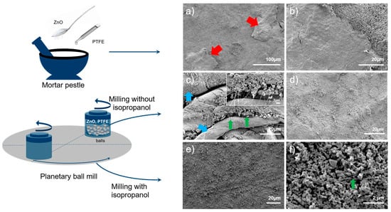
Figure 1.
Typical SEM images of the ZnO-PTFE anodes prepared via different preparation methods: (a,b) anode mixture prepared via mortar pestle, followed by die pressing for anode pellet preparation; (c,d) anode mixture prepared via dry ball mill, followed by die pressing for anode pellet preparation, inset shows thinner fibers; and (e,f) anode mixture prepared via wet ball mill, followed by roll press for anode pellet preparation.
Enhancing the distribution of PTFE, particularly with thinner PTFE fibers, could further improve pellet integrity. Inspired by the previous work of Janowitz et al. [36], isopropanol was added to the ZnO:PTFE mixture (with a weight ratio of ZnO:PTFE:isopropanol of 85:15:50) during ball-milling to achieve better mixing uniformity. Figure S2 presents typical images of the anode mixture prepared via ball milling using isopropanol. These images show that the PTFE fibers are well-distributed, with an average diameter of approximately 50 nm, and ZnO nanoparticles are attached to these fibers. The formation of a well-distributed PTFE fibrous network with ZnO particles is a direct result of isopropanol-assisted ball milling. In contrast to dry milling, which suffers from inefficient energy transfer, leading to material agglomeration and a less uniform mixture, the use of isopropanol as a liquid processing medium is crucial for achieving improved results. Isopropanol serves two primary functions: first, it acts as an effective dispersing agent for both the ZnO nanoparticles and the PTFE microparticles, creating a homogeneous slurry. This ensures uniformity of the high-impact shear forces generated by the milling media. Second, by wetting the newly formed surfaces of the PTFE, isopropanol mitigates re-agglomeration driven by van der Waals forces, thereby promoting extensive fibrillation. The ZnO nanoparticles act as localized stress concentrators. During milling, impacts from the grinding balls press the ZnO particles into the softer, ductile PTFE matrix. This focused pressure initiates fibrillation, drawing the PTFE into fine fibers. As these fibers are generated, they entangle and form a robust network, mechanically entrapping the well-dispersed ZnO particles. As a result, the increased number of PTFE fibers has resulted in a more effective binder network distribution, allowing for a higher amount of ZnO particles per unit volume of PTFE compared to thicker fibers. Another important advantage of this preparation method is that anode pellets with defined shapes can be prepared without the need for intensive densification, which is crucial for achieving high porosity in the pellets. A roll press was used for this purpose. Figure 1e,f show the SEM images of the prepared electrode. The low magnification image (Figure 1e) shows a flat surface of the anode, whereas the higher magnification image (Figure 1f) reveals the presence of PTFE fibers and ZnO particles attached to them.
When these anodes were immersed in a 6 M KOH solution, they showed no signs of disintegration. To assess the open porosity of these anodes, as open pores would allow electrolyte access during electrochemical cycling, measurements were conducted using Archimedes’ principle [37,38,39,40] with isopropanol. The results indicated that the anodes produced through roll pressing using a wet ball-milled mixture exhibited a reproducible (open) porosity of 63% (±1). This porosity value aligns well within the optimal range of 60–80% recommended for zinc–air battery anodes [19,41,42]. Thus, a stable, porous anode that remains stable in a 6 M KOH solution has been successfully fabricated.
3.2. Structural and Electrochemical Performance of the Porous Anode
X-ray diffraction (XRD) measurements were conducted on the ZnO-PTFE anode prepared using a wet ball mill process. As depicted in Figure 2a, the diffraction pattern displays several sharp, well-defined peaks, which indicate the crystalline nature of the ZnO phase within the ZnO-PTFE anode. The prominent peaks correspond to the (100), (002), (101), (102), and (110) planes of ZnO, along with additional higher-angle reflections (database: 96-210-7060), confirming that the ZnO crystalline structure was preserved during the ball milling process. Furthermore, the peak observed around 8° is associated with the presence of PTFE (database: 96-410-8430) in the sample.
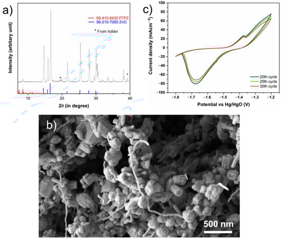
Figure 2.
(a) XRD of the ZnO-PTFE anode prepared via wet ball mill showing the ZnO peaks; (b) high resolution images showing ZnO attached PTFE fibers and electrode porosity; (c) CV analysis of the ZnO-PTFE anode between −1.2 V and −1.8V with respect to Hg/HgO.
The high-resolution SEM images, Figure 2b, of the prepared electrode clearly demonstrate that ZnO nanoparticles are attached to the thin PTFE fibers. This high-resolution image also shows the inherent porosity of the electrodes. Additional lower magnification images can also be seen in Figure S3.
To investigate the electrochemical behavior and cycling stability of the electrode, cyclic voltammetry (CV) was performed. Figure 2c presents the 20th, 25th, and 30th CV cycles recorded at a scan rate of 5 mV s−1 within a potential window of −1.8 V to −1.2 V vs. Hg/HgO. These cycles were specifically chosen for analysis as they would reflect the stabilized operational state of the electrode.The voltammograms display characteristic peaks indicative of the electrochemical behavior of zinc in an alkaline electrolyte. During the anodic sweep, as the potential crosses approximately −1.5 V, the net current becomes anodic; in the region between −1.5 V and −1.35 V, the net current rises steeply. This potential range corresponds to the active dissolution of zinc, which is primarily controlled by charge transfer, leading to the formation of soluble zincate species (Zn(OH)42−) [43,44]. A distinct anodic shoulder is observed around −1.35 V, representing the onset of pre-passivation, which is attributed to a dissolution-precipitation mechanism.
As anodic dissolution continues, the concentration of zincate ions at the electrode-electrolyte interface increases, leading to a supersaturated state. This results in the precipitation of a porous, non-adherent “Type I” zinc oxide/hydroxide film on the electrode surface [44]. The formation of this porous layer temporarily impedes the dissolution reaction, causing the observed current shoulder before the onset of full passivation at more positive potentials, which was avoided in this study.
On the reverse cathodic sweep, a prominent reduction peak is observed with a maximum current density at approximately −1.67 V. This peak corresponds to the reduction of metallic zinc from the zincate ions [43,45]. The high degree of overlap between the 20th, 25th, and 30th cycles demonstrates excellent cycling stability and high electrochemical reversibility. A slight, progressive decrease in peak current densities for both the anodic and cathodic processes is observable. These minor changes may be attributed to subtle morphological changes in the electrode surface or the incomplete reduction of the passivating oxide film during the cathodic scan, leading to a potential gradual loss of active surface area over extended cycling.
All electrochemical performance evaluations were conducted using a three-electrode half-cell configuration. This setup was intentionally chosen to isolate and fundamentally assess the intrinsic properties of the fabricated anode. By decoupling the anode’s performance from variables introduced by other components (e.g., the air cathode), this approach allows for a direct and unambiguous correlation between our fabrication method and the observed electrochemical behavior, such as cycling stability and rate capability. This provides a foundational understanding of the anode’s performance before its integration into more complex full-cell systems in the future. Figure 3a shows the galvanostatic cycling behavior of the anodes that were prepared via the wet ball milling method. A two-step electrochemical cycling process was employed. In the first step, to convert the zinc oxide particles to zinc, the anodes were charged in a 6 M KOH solution at a rate of 160 mA gZn−1 to a theoretically calculated capacity value of 820 mAh gZn−1. This activation step would also improve the charge transfer resistance due to the better electronic conductivity of zinc compared to zinc oxide (ranging from 10−10 to 10−3 S cm−1) [26]. The SEM image of the fully charged anode, which illustrates Zn particles attached to the PTFE fibers, including the corresponding EDS analysis, can be found in the Supplementary Materials (Figure S4). In the second stage, the anodes were subjected to galvanostatic cycling at a rate of 60 mA gZn−1 in 6 M KOH + 0.2M ZnO electrolyte. The addition of ZnO to a 6 M KOH solution was intended to reduce Zn corrosion and HER [46].
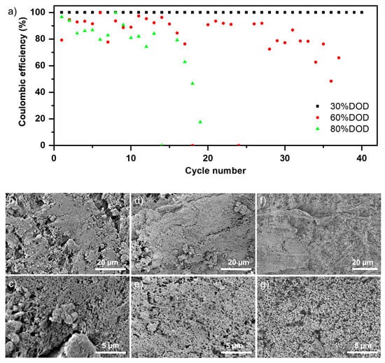
Figure 3.
(a) Comparing Coulombic efficiencies across cycles at 30%, 60%, and 80% depth of charge and discharge (DOD) levels, with a constant current of 60 mA gZn−1. Typical SEM images of anodes cycled with various DODs (b,c) anodes cycled with 80% DOD after 20 cycles; (d,e) anodes cycled with 60% DOD after 30 cycles; (f,g) anodes cycled with 30% DOD after 40 cycles.
Three different depths of charge and discharge (DODs)—30%, 60%, and 80%—were compared to analyze their effects on coulombic efficiency (CE) and cycle number. Figure 3a illustrates the relationship between CE and cycle number for these DODs, with CE calculated based on material utilization. Initially, the CE of the anodes cycled at 80% and 60% DOD fluctuated before experiencing significant performance degradation. The CE of the anode cycled at 80% DOD continuously decreased, reaching approximately 80% after 10 cycles and dropping below 20% after 20 cycles. The CE for the anode cycled at 60% DOD dropped to about 90% after 20 cycles and around 50% after 30 cycles. The corresponding charge–discharge capacities are plotted in Figure S5. It can be seen that for the higher DODs (60%, 80%), even though the charge capacity is mostly maintained throughout the tested cycles, the discharge capacity is reduced over the cycles. This could be linked to loss of active zinc and/or surface passivation. The anodes operated at a 30% DOD demonstrated better electrochemical stability, maintaining a stable coulombic efficiency of 95% over 40 cycles. The rapid decline in CE at higher DODs can be attributed to an increased amount of dissolved zinc in the electrolyte due to the zinc oxidation reaction. This may lead to negative effects, such as dendrite formation and ZnO precipitation. Moreover, increased dissolution rates at higher DODs can result in empty pores within the anode, compromising its electrical conductivity [47]. These cumulative effects ultimately reduce CE at higher DODs.
However, even after cycling at higher DODs, the overall structure of the anode remained intact and did not degrade. This stability can be attributed to the PTFE scaffold. To investigate whether any ZnO particles were still attached to the PTFE fibers, a series of post-mortem SEM analyses was carried out on the cycled electrodes. Typical SEM images of the cycled anodes at 80%, 60%, and 30% DODs are shown in Figure 3b,c, Figure 3d,e, and Figure 3f,g, respectively. These SEM images confirm that the active materials continue to adhere to the thin PTFE fiber network. While Figure 3b–e reveal additional sprouts like deposition that could be responsible for dendrite formation, no external deposition was observed in the SEM images of the cycled anode at 30% DOD (Figure 3f,g). Further, electrodes cycled at higher DODs showed more porosity. This can be linked to the loss of active material during cycling. To investigate the suitability of the prepared anode for long-term cycling, a DOD of 30% (equivalent to an absolute cell capacity of 100–140 mAh) was selected. Although this DOD may appear modest, it is adequate due to the relatively high specific energy of Zn-air batteries [26]. A current density of 60 mA gZn−1 (approximately 10 mA cm−2, based on the geometrical surface area of the electrode) was chosen for the cycling. This current density is consistent with those commonly used in the literature for zinc–air batteries [21,23,48].
Figure 4a represents the results of the CE versus cycle number during long-term cycling. The as-prepared anode delivered a discharge capacity of approximately 230 mAh gZn−1 over 350 cycles, achieving a CE of around 95% before experiencing capacity fading. Although the number of charge–discharge cycles in this three-electrode cell cannot be directly compared to those in a full-cell, this high number of cycles, combined with a high CE, demonstrates the prepared anode’s suitability for long-term cycling.
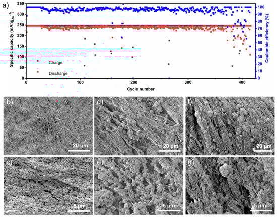
Figure 4.
(a) Long-term charge–discharge capacities and Coulombic efficiency with 30% DOD at 60 mA gZn−1. Typical SEM analysis of anodes cycled at different cycle numbers (b,c) anodes after 1st cycle; (d,e) anodes cycled up to 150 cycles; (f,g) anodes cycled up to 400 cycles.
To investigate the underlying reasons for this performance over a span of 4 months, a series of microscopic analyses were carried out during various stages of the charging and discharging process. Figure 4b–g illustrate the SEM analyses conducted after one, 150, and 400 cycles. The SEM images of the anodes after the first cycle show active particles attached to PTFE fibers. Compared to the pristine electrode, ZnO particles became more spherical. These images (Figure 4b,c) are very similar to those taken after 40 cycles (Figure 3f,g). In both cases, minimal external deposition is noticeable. In contrast, the SEM images of anodes after 150 and 400 cycles (Figure 4d,e and Figure 4f,g, respectively) reveal the presence of flower-like deposits alongside the adhered active nanoparticles with PTFE fibers. It can be suggested that while the anchored ZnO nanoparticles transformed from zinc oxide to zinc during cycling, the flower-like formations resulted from Zn deposition from the electrolyte. These deposits have the potential to contribute to dendrite formation [17]. However, the main focus here is the persistence of the adhered active nanoparticles with the PTFE fiber network, even after cycling for up to 400 cycles. This indicates the successful fabrication of an anode architecture suitable for long-term cycling. The porosity of this architecture provides sufficient space to accommodate the volume changes from zinc to zinc oxide [19], thereby ensuring mechanical stability. Furthermore, the high surface area of the porous anode minimizes local current densities and reduces dendrite growth [3].
3.3. Electrochemical Performance of Anode with Incorporated Electrode Additive
Previous studies have reported that the presence of Bi2O3, owing to its high hydrogen evolution overpotential, reduces the formation of hydrogen gas during Zn deposition [28,30]. Additionally, Qu et al. demonstrated that the presence of Bi2O3 on the electrode surface mitigates polarization effects and limits dendrite formation [29]. Thus, Bi2O3 was selected as the electrode additive. To demonstrate the potential of the fabrication strategy for integrating electrode additives, we prepared electrodes using Bi2O3. This strategy facilitated the straightforward incorporation of additives into the anode; the desired amounts of electrode additives were added to ZnO and PTFE during the wet ball milling process, while the remaining steps in anode preparation were unchanged. Anodes with 1 wt.%, 2 wt.%, and 5 wt.% of Bi2O3 additives were produced. To confirm that the electrodes with additives could maintain porosity, we measured their porosity using Archimedes’ principle. As shown in Table S1, the estimated porosity of these electrodes is approximately 63%. This finding demonstrates the effectiveness of our method in achieving a porous electrode that includes electrode additives.
Figure 5a compares the performance of anodes prepared with different amounts of Bi2O3 additives. All the anodes with different amounts of Bi2O3 additives achieved the discharge capacity of 246 mAh gZn−1 at a current density of 60 mA gZn−1. Similarly, at 100 and 120 mA gZn−1 current densities, all anodes maintained this capacity of 246 mAh gZn−1. However, at 180 mA gZn−1, apart from the electrodes with 2 wt.% Bi2O3 additives, other electrodes, namely with 1 wt.% and 5 wt.% additives begin to show fluctuations in discharge capacity. Only the anodes with 2 wt.% Bi2O3 still delivered a stable discharge capacity of 246 mAh gZn−1. This finding is consistent with previous research by Park et al. [28], who also concluded that a similar composition resulted in the best performance. Even though the exact reason for the best performance of the 2 wt.% Bi2O3 concentration is not yet fully understood and requires further investigations, this concentration was selected for further investigations.
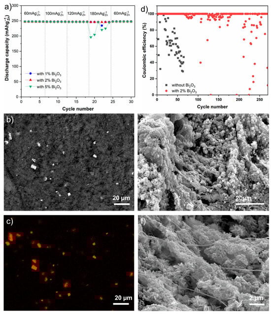
Figure 5.
Electrochemical performance and physical characterization of porous anode with electrode additive. (a) Variation of discharge capacity of anode with different concentration of Bi2O3 at different current densities; (b) the BSE image and the corresponding (c) EDS map the pristine anode with 2% Bi2O3; (d) comparison of coulombic efficiency between anode with and without 2% Bi2O3 during long-term cycling at 120 mA gZn−1 at 30% DOD; and (e,f) typical SEM images of the anode with 2% Bi2O3 cycled after 250 cycles.
To assess the distribution of Bi2O3, SEM and EDS measurements were carried out on an anode containing 2 wt.% Bi2O3. Figure 5b presents a typical backscattered electron (BSE) image, with the corresponding elemental mapping of Bi shown in Figure 5c. The bright spots observed in both the BSE image and the Bi elemental map indicate the presence of Bi2O3. Figure 5b,c illustrate that Bi2O3 was uniformly distributed throughout the anode, highlighting the effectiveness of the preparation method.
Long-term cycling experiments were conducted using anodes containing 2 wt.% Bi2O3 at a current density of 120 mA gZn−1 and a DOD of 30%. Figure 5d compares the coulombic efficiency of the anode with 2 wt.% Bi2O3 to that of the anode without an additive. At this current density, the anode without an additive exhibited severe capacity fading after just 15 cycles. Figure S6 illustrates the comparison of charge–discharge capacity for the anode without any additives. It is evident that at higher current densities, although the charge capacity is largely maintained throughout the cycles, the discharge capacity decreases over time. This reduction may be attributed to the loss of active zinc and/or surface passivation. Additionally, Figure S7 presents a comparison of the charge–discharge profiles at different cycles for current densities of 60 mA gZn−1 and 120 mA gZn−1. As expected, increasing the current density results in a higher overpotential.However, the anode with 2 wt.% Bi2O3 achieved 200 cycles with a 100% CE (at 30% DOD). This demonstrates the advantages of combining porous Zn anodes with electrode additives, resulting in improved cycling stability and performance in Zn-air batteries.
The BSE image and the corresponding EDS mapping of the cycled anode with 2 wt.% Bi2O3 (Figure S8) confirm that Bi2O3 particles are still present. Additionally, secondary electron images in Figure 5e,f reveal that even though sprout-like deposits are evident at the end of the 250 cycles, the active particles have remained adhered to the PTFE fibers. D.-J. Park et al. previously integrated Bi2O3 additive into a pressed ZnO-PTFE anode using a roll press [28]. They reported achieving a specific capacity of approximately 100 mAh g−1 after 20 cycles at a C/20 rate with a 3 wt.% Bi2O3 additive. Although the results cannot be directly compared due to differences in depth of discharge (DOD) and the absence of porosity data, the 100% coulombic efficiency achieved over 200 cycles, spanning over two months at a current density of 120 mA gZn−1 in this study, demonstrates the effectiveness of the porous electrode preparation strategy.
To examine the effect of Bi2O3 on HER, gas chromatography was conducted during charging with the 2 wt.% Bi2O3 anodes. The results demonstrated a 40% reduction in hydrogen production during charging at 60 mA gZn−1 for 1 h when using the 2 wt.% Bi2O3 electrode additives, compared to the anode without the additive. This indicates that the addition of Bi2O3 significantly reduces HER. These results are provided in Supplementary Materials (Table S2).
This straightforward and scalable strategy has successfully enabled the fabrication of an anode architecture that can sustain long-term cycling at high current densities. It should be pointed out, further surface modifications of Zn/ZnO should be explored to minimize zinc corrosion in KOH. Notably, anodes incorporating these types of active nanoparticles can be prepared using the same procedure.
4. Conclusions
In this study, we developed a scalable and versatile fabrication method using wet ball milling and roll pressing to create a robust and porous ZnO anode architecture. The effectiveness of this approach is demonstrated by its ability to consistently achieve a desirable porosity of approximately 63%. This technique results in a structure where ZnO nanoparticles are anchored onto a stable polytetrafluoroethylene (PTFE) fiber scaffold. Cyclic voltammetry confirmed the highly reversible nature of the electrode’s electrochemical processes. The anode demonstrated good cycling stability, delivering over 400 cycles, maintaining a 30% depth of discharge with approximately 95% coulombic efficiency at a current density of 60 mA gZn−1. Moreover, the developed framework serves as an ideal platform for incorporating electrode additives. For example, incorporating 2 wt.% Bi2O3 significantly improved the electrode performance (over 200 cycles at 120 mA gZn−1 with nearly 100% coulombic efficiency). We attribute this enhancement to the additive’s role in reducing hydrogen evolution and potentially mitigating electrode passivation. Furthermore, the results reveal that the coulombic efficiency is decreasing due to a declining discharge capacity while the charge capacity remains relatively stable.
These findings validate a powerful strategy that synergistically combines engineered anode porosity with the targeted action of electrode additives. By demonstrating the anode’s intrinsic benefits in a half-cell configuration, we establish a strong foundation for future advancements. A critical next step is to translate these promising results into a practical full-cell zinc–air battery to evaluate performance under realistic operating conditions. Integrating this optimized anode with advanced 3D foam current collectors within such a full-cell system presents a clear path to enhance cycling performance and validate its practical viability. Furthermore, the inherent flexibility of our fabrication process is well-suited for incorporating coated ZnO nanoparticles, offering a promising route to mitigate zinc corrosion and extend the cycle life of aqueous zinc-based batteries.
Supplementary Materials
The following supporting information can be downloaded at: https://www.mdpi.com/article/10.3390/batteries11100359/s1. Figure S1: Schematic representation of the cell for H2 evolution measurement; Figure S2: Typical SEM image of wet ball-milled anode mixture showing thin PTFE fibers run throughout the anode mixture; Figure S3: Additional SEM images of the pristine ZnO-PTFE electrode prepared using wet ball mill anode mixture; Figure S4: Typical SEM and EDS results of full charged anode (after gold coating). Figure S5: Charge–discharge capacity, and the corresponding coulombic efficiency, for (a) 80%, (b) 60% and (c) 30% DOD at a constant current of 60 mA gZn−1. Figure S6: Specific capacities and coulombic efficiencies of ZnO-PTFE anode with 30% DOD at 120 mA gZn−1; Figure S7: Comparison of potential profiles of the ZnO-PTFE anodes during charge–discharge at 60 and 120 mA gZn−1 at (a) 5th, (b) 30th and (c) 50th cycles; Figure S8: The BSE image and the corresponding EDS map of the 2% Bi2O3 anode cycled with 120 mA gZn−1at 30% DOD; Table S1: Measured open porosity of electrodes with additives using Archimedes’ principle.; Table S2: Measured H2 evolution during charging through gas chromatography.
Author Contributions
Conceptualization, S.D. and Y.E.D.; experimental work and data analysis, S.D.; writing—original draft preparation, S.D.; writing—review and editing, S.D., Y.E.D., E.I., H.K. and H.T.; supervision, Y.E.D., H.T. and R.-A.E.; project administration, H.T. and R.-A.E. All authors have read and agreed to the published version of the manuscript.
Funding
This research was funded by the German Federal Ministry of Education and Research (BMBF) within the project Verbundvorhaben iNEW2.0 (03SF0627A).
Data Availability Statement
The original contributions presented in this study are included in the article and Supplementary Materials. Further inquiries can be directed to the corresponding author.
Conflicts of Interest
Authors Sarmila Dutta, Yasin Emre Durmus, Eunmi Im, Hans Kungl, Hermann Tempel and Rüdiger-A. Eichel were employed by the Institute of Energy Technologies IET-1, Forschungszentrum Jülich GmbH. The authors declare that the research was conducted in the absence of any commercial or financial relationships that could be construed as a potential conflict of interest.
References
- Pei, P.; Wang, K.; Ma, Z. Technologies for Extending Zinc–Air Battery’s Cyclelife: A Review. Appl. Energy 2014, 128, 315–324. [Google Scholar] [CrossRef]
- Rahman, M.A.; Wang, X.; Wen, C. High Energy Density Metal-Air Batteries: A Review. J. Electrochem. Soc. 2013, 160, A1759–A1771. [Google Scholar] [CrossRef]
- Fu, J.; Cano, Z.P.; Park, M.G.; Yu, A.; Fowler, M.; Chen, Z. Electrically Rechargeable Zinc–Air Batteries: Progress, Challenges, and Perspectives. Adv. Mater. 2017, 29, 1604685. [Google Scholar] [CrossRef]
- Harting, K.; Kunz, U.; Turek, T. Zinc-Air Batteries: Prospects and Challenges for Future Improvement. Z. Für Phys. Chem. 2012, 226, 151–166. [Google Scholar] [CrossRef]
- Gu, P.; Zheng, M.; Zhao, Q.; Xiao, X.; Xue, H.; Pang, H. Rechargeable Zinc–Air Batteries: A Promising Way to Green Energy. J. Mater. Chem. A 2017, 5, 7651–7666. [Google Scholar] [CrossRef]
- Liu, Q.; Pan, Z.; Wang, E.; An, L.; Sun, G. Aqueous Metal-Air Batteries: Fundamentals and Applications. Energy Storage Mater. 2020, 27, 478–505. [Google Scholar] [CrossRef]
- Weinrich, H.; Durmus, Y.E.; Tempel, H.; Kungl, H.; Eichel, R.-A. Silicon and Iron as Resource-Efficient Anode Materials for Ambient-Temperature Metal-Air Batteries: A Review. Materials 2019, 12, 2134. [Google Scholar] [CrossRef] [PubMed]
- Lv, X.; Wang, Z.; Lai, Z.; Liu, Y.; Ma, T.; Geng, J.; Yuan, Z. Rechargeable Zinc–Air Batteries: Advances, Challenges, and Prospects. Small 2024, 20, 2306396. [Google Scholar] [CrossRef]
- Zhu, Z.; Jiang, T.; Ali, M.; Meng, Y.; Jin, Y.; Cui, Y.; Chen, W. Rechargeable Batteries for Grid Scale Energy Storage. Chem. Rev. 2022, 122, 16610–16751. [Google Scholar] [CrossRef] [PubMed]
- Li, Y.; Lu, J. Metal–Air Batteries: Will They Be the Future Electrochemical Energy Storage Device of Choice? ACS Energy Lett. 2017, 2, 1370–1377. [Google Scholar] [CrossRef]
- Wang, Q.; Kaushik, S.; Xiao, X.; Xu, Q. Sustainable Zinc–Air Battery Chemistry: Advances, Challenges and Prospects. Chem. Soc. Rev. 2023, 52, 6139–6190. [Google Scholar] [CrossRef] [PubMed]
- Mainar, A.R.; Iruin, E.; Colmenares, L.C.; Kvasha, A.; De Meatza, I.; Bengoechea, M.; Leonet, O.; Boyano, I.; Zhang, Z.; Blazquez, J.A. An Overview of Progress in Electrolytes for Secondary Zinc-Air Batteries and Other Storage Systems Based on Zinc. J. Energy Storage 2018, 15, 304–328. [Google Scholar] [CrossRef]
- Zhao, Z.; Fan, X.; Ding, J.; Hu, W.; Zhong, C.; Lu, J. Challenges in Zinc Electrodes for Alkaline Zinc–Air Batteries: Obstacles to Commercialization. ACS Energy Lett. 2019, 4, 2259–2270. [Google Scholar] [CrossRef]
- Prakoso, B.; Mahbub, M.A.A.; Yilmaz, M.; Khoiruddin; Wenten, I.G.; Handoko, A.D.; Sumboja, A. Recent Progress in Extending the Cycle-Life of Secondary Zn-Air Batteries. ChemNanoMat 2021, 7, 354–367. [Google Scholar] [CrossRef]
- Mainar, A.R.; Colmenares, L.C.; Grande, H.-J.; Blázquez, J.A. Enhancing the Cycle Life of a Zinc–Air Battery by Means of Electrolyte Additives and Zinc Surface Protection. Batteries 2018, 4, 46. [Google Scholar] [CrossRef]
- Stamm, J. Modeling Nucleation and Growth of Zinc Oxide during Discharge of Primary Zinc-Air Batteries. J. Power Sources 2017, 360, 136–149. [Google Scholar] [CrossRef]
- Deckenbach, D.; Schneider, J.J. A 3D Hierarchically Porous Nanoscale ZnO Anode for High-Energy Rechargeable Zinc-Air Batteries. J. Power Sources 2021, 488, 229393. [Google Scholar] [CrossRef]
- Lei, L.; Sun, Y.; Wang, X.; Jiang, Y.; Li, J. Strategies to Enhance Corrosion Resistance of Zn Electrodes for Next Generation Batteries. Front. Mater. 2020, 7, 96. [Google Scholar] [CrossRef]
- Mainar, A.R.; Colmenares, L.C.; Blázquez, J.A.; Urdampilleta, I. A Brief Overview of Secondary Zinc Anode Development: The Key of Improving Zinc-Based Energy Storage Systems. Int. J. Energy Res. 2018, 42, 903–918. [Google Scholar] [CrossRef]
- Minakshi, M.; Appadoo, D.; Martin, D.E. The Anodic Behavior of Planar and Porous Zinc Electrodes in Alkaline Electrolyte. Electrochem. Solid-State Lett. 2010, 13, A77. [Google Scholar] [CrossRef]
- Li, L.; Tsang, Y.C.A.; Xiao, D.; Zhu, G.; Zhi, C.; Chen, Q. Phase-Transition Tailored Nanoporous Zinc Metal Electrodes for Rechargeable Alkaline Zinc-Nickel Oxide Hydroxide and Zinc-Air Batteries. Nat. Commun. 2022, 13, 2870. [Google Scholar] [CrossRef]
- Yang, D.; Li, J.; Liu, C.; Xing, W.; Zhu, J. Design Strategy and Comprehensive Performance Assessment towards Zn Anode for Alkaline Rechargeable Batteries. J. Energy Chem. 2023, 82, 122–138. [Google Scholar] [CrossRef]
- Liu, P.; Ling, X.; Zhong, C.; Deng, Y.; Han, X.; Hu, W. Porous Zinc Anode Design for Zn-Air Chemistry. Front. Chem. 2019, 7, 656. [Google Scholar] [CrossRef]
- Chamoun, M.; Hertzberg, B.J.; Gupta, T.; Davies, D.; Bhadra, S.; Van Tassell, B.; Erdonmez, C.; Steingart, D.A. Hyper-Dendritic Nanoporous Zinc Foam Anodes. NPG Asia Mater. 2015, 7, e178. [Google Scholar] [CrossRef]
- Qu, S.; Liu, B.; Fan, X.; Liu, X.; Liu, J.; Ding, J.; Han, X.; Deng, Y.; Hu, W.; Zhong, C. 3D Foam Anode and Hydrogel Electrolyte for High-Performance and Stable Flexible Zinc–Air Battery. ChemistrySelect 2020, 5, 8305–8310. [Google Scholar] [CrossRef]
- Parker, J.F.; Chervin, C.N.; Nelson, E.S.; Rolison, D.R.; Long, J.W. Wiring Zinc in Three Dimensions Re-Writes Battery Performance—Dendrite-Free Cycling. Energy Env. Sci. 2014, 7, 1117–1124. [Google Scholar] [CrossRef]
- Parker, J.F.; Nelson, E.S.; Wattendorf, M.D.; Chervin, C.N.; Long, J.W.; Rolison, D.R. Retaining the 3D Framework of Zinc Sponge Anodes upon Deep Discharge in Zn–Air Cells. ACS Appl. Mater. Interfaces 2014, 6, 19471–19476. [Google Scholar] [CrossRef]
- Park, D.-J.; Aremu, E.O.; Ryu, K.-S. Bismuth Oxide as an Excellent Anode Additive for Inhibiting Dendrite Formation in Zinc-Air Secondary Batteries. Appl. Surf. Sci. 2018, 456, 507–514. [Google Scholar] [CrossRef]
- Qu, D.; Wang, L.; Zheng, D.; Xiao, L.; Deng, B.; Qu, D. An Asymmetric Supercapacitor with Highly Dispersed Nano-Bi2O3 and Active Carbon Electrodes. J. Power Sources 2014, 269, 129–135. [Google Scholar] [CrossRef]
- Park, J.H.; Schneider, N.M.; Steingart, D.A.; Deligianni, H.; Kodambaka, S.; Ross, F.M. Control of Growth Front Evolution by Bi Additives during ZnAu Electrodeposition. Nano Lett. 2018, 18, 1093–1098. [Google Scholar] [CrossRef]
- Aremu, E.O.; Park, D.-J.; Ryu, K.-S. The Effects of Anode Additives towards Suppressing Dendrite Growth and Hydrogen Gas Evolution Reaction in Zn-Air Secondary Batteries. Ionics 2019, 25, 4197–4207. [Google Scholar] [CrossRef]
- Da, Y.; Zhao, F.; Shi, J.; Zhang, Z. Effects of Ultrafine Bismuth Powder on the Properties of Zinc Electrodes in Zinc-Air Batteries. J. Electron. Mater. 2020, 49, 2479–2490. [Google Scholar] [CrossRef]
- Lee, Y.-S.; Ryu, K.-S. Effects of Aluminum and Silicon as Additive Materials for the Zinc Anode in Zn-Air Batteries. J. Korean Electrochem. Soc. 2018, 21, 12–20. [Google Scholar] [CrossRef]
- Stock, D.; Dongmo, S.; Miyazaki, K.; Abe, T.; Janek, J.; Schröder, D. Towards Zinc-Oxygen Batteries with Enhanced Cycling Stability: The Benefit of Anion-Exchange Ionomer for Zinc Sponge Anodes. J. Power Sources 2018, 395, 195–204. [Google Scholar] [CrossRef]
- Yan, Z.; Wang, E.; Jiang, L.; Sun, G. Superior Cycling Stability and High Rate Capability of Three-Dimensional Zn/Cu Foam Electrodes for Zinc-Based Alkaline Batteries. RSC Adv. 2015, 5, 83781–83787. [Google Scholar] [CrossRef]
- Janowitz, K.; Woltering, P.; Beckmann, R.; Steinmetz, T.; Kiefer, R.; Dulle, K.-H.; Funck, F.; Kohnke, H.-J. Method for Producing Gas Diffusion Electrodes. EP 1402587B1, 16 March 2004. [Google Scholar]
- Erol, M.; Ertugrul, O. HIPed TiO2 Dense Pellets with Improved Photocatalytic Performance. Ceram. Int. 2018, 44, 2991–2999. [Google Scholar] [CrossRef]
- Westphal, E.; Seitz, H. Porosity and Density Measurement of Additively Manufactured Components: A Comparative Analysis of Measurement Methods across Processes and Materials. Mater. Sci. Addit. Manuf. 2025, 4, 025090010. [Google Scholar] [CrossRef]
- Klobes, P.; Meyer, K.; Munro, R.G. Porosity and Specific Surface Area Measurements for Solid Materials; NIST Recommended Practice Guide; NIST: Gaithersburg, MD, USA, 2006. [Google Scholar]
- Martínez, C.; Guerra, C.; Silva, D.; Cubillos, M.; Briones, F.; Muñoz, L.; Páez, M.A.; Aguilar, C.; Sancy, M. Effect of Porosity on Mechanical and Electrochemical Properties of Ti–6Al–4V Alloy. Electrochim. Acta 2020, 338, 135858. [Google Scholar] [CrossRef]
- Ko, J.S.; Bishop, K.; Seitzman, N.; Chen, B.-R.; Toney, M.F.; Nelson Weker, J. Highly Reversible Plating/Stripping of Porous Zinc Anodes for Multivalent Zinc Batteries. J. Electrochem. Soc. 2020, 167, 140520. [Google Scholar] [CrossRef]
- Hopkins, B.J.; Sassin, M.B.; Parker, J.F.; Long, J.W.; Rolison, D.R. Zinc-Sponge Battery Electrodes That Suppress Dendrites. J. Vis. Exp. 2020, 163, 61770. [Google Scholar] [CrossRef]
- Cai, M.; Park, S. Spectroelectrochemical Studies on Dissolution and Passivation of Zinc Electrodes in Alkaline Solutions. J. Electrochem. Soc. 1996, 143, 2125–2131. [Google Scholar] [CrossRef]
- Zhang, X.G. Corrosion and Electrochemistry of Zinc; Springer: Boston, MA, USA, 1996; ISBN 978-1-4757-9879-1. [Google Scholar]
- Hwang, B.; Oh, E.-S.; Kim, K. Observation of Electrochemical Reactions at Zn Electrodes in Zn-Air Secondary Batteries. Electrochim. Acta 2016, 216, 484–489. [Google Scholar] [CrossRef]
- Lim, M.B.; Lambert, T.N.; Ruiz, E.I. Effect of ZnO-Saturated Electrolyte on Rechargeable Alkaline Zinc Batteries at Increased Depth-of-Discharge. J. Electrochem. Soc. 2020, 167, 060508. [Google Scholar] [CrossRef]
- Turney, D.E.; Gallaway, J.W.; Yadav, G.G.; Ramirez, R.; Nyce, M.; Banerjee, S.; Chen-Wiegart, Y.K.; Wang, J.; D’Ambrose, M.J.; Kolhekar, S.; et al. Rechargeable Zinc Alkaline Anodes for Long-Cycle Energy Storage. Chem. Mater. 2017, 29, 4819–4832. [Google Scholar] [CrossRef]
- Khezri, R.; Jirasattayaporn, K.; Abbasi, A.; Maiyalagan, T.; Mohamad, A.A.; Kheawhom, S. Three-Dimensional Fibrous Iron as Anode Current Collector for Rechargeable Zinc–Air Batteries. Energies 2020, 13, 1429. [Google Scholar] [CrossRef]
Disclaimer/Publisher’s Note: The statements, opinions and data contained in all publications are solely those of the individual author(s) and contributor(s) and not of MDPI and/or the editor(s). MDPI and/or the editor(s) disclaim responsibility for any injury to people or property resulting from any ideas, methods, instructions or products referred to in the content. |
© 2025 by the authors. Licensee MDPI, Basel, Switzerland. This article is an open access article distributed under the terms and conditions of the Creative Commons Attribution (CC BY) license (https://creativecommons.org/licenses/by/4.0/).