Review

Swelling Mechanisms, Diagnostic Applications, and Mitigation Strategies in Lithium-Ion Batteries

1
Center for Advanced Life Cycle Engineering (CALCE), University of Maryland, College Park, MD 20742, USA
2
LUMS Energy Institute (LEI), Syed Babar Ali School of Science and Engineering (SBASSE), Lahore University of Management Sciences (LUMS), Lahore 54792, Pakistan
*
Author to whom correspondence should be addressed.
Batteries 2025, 11(10), 356; https://doi.org/10.3390/batteries11100356
Submission received: 12 August 2025 / Revised: 23 September 2025 / Accepted: 23 September 2025 / Published: 28 September 2025

Abstract

Electrochemical processes within a lithium-ion battery cause electrode expansion and gas generation, thus resulting in battery swelling and, in severe cases, reliability and safety issues. This paper presents the mechanisms responsible for swelling, including thermal expansion, lithium intercalation, electrode interphase layer growth, lithium plating, and gas generation, while highlighting their dependence on material properties, design considerations, C-rate, temperature, state of charge (SoC), and voltage. The paper then discusses how swelling correlates with capacity fade, impedance rise, and thermal runaway, and demonstrates the potential of using swelling as a diagnostic and prognostic metric for battery health. Swelling models that connect microscopic mechanisms to macroscopic deformation are then presented. Finally, the paper presents strategies to mitigate swelling, including materials engineering, surface coatings, electrolyte formulation, and mechanical design modifications.

Graphical Abstract

1. Introduction

Swelling in lithium-ion batteries (LIBs) arises from electrochemical, mechanical, and thermal mechanisms [1], and include volumetric expansion of electrode materials during intercalation and phase transformations, expansion of the solid electrolyte interphase (SEI) and cathode electrolyte interphase (CEI), expansion due to lithium plating, and expansion due to gas generation resulting from electrolyte decomposition and interfacial breakdown [2,3]. These mechanisms can induce both reversible and irreversible dimensional changes [4,5,6], ranging from a few percent during normal cycling to over 45% in aged cells [7]. Swelling, in turn, can affect the performance and safety of the battery.
Grimsmann et al. [6] observed that battery swelling is a key driver of capacity loss and safety risks. Mohtat et al. [8] demonstrated that cells undergo reversible (cycle-to-cycle) and irreversible (long-term) expansion dependent on the C-rate and temperature, which correlate to capacity fade. Li et al. showed that swelling increased steadily with cycling and can be associated with accelerated capacity fade [9]. Heugel et al. [10] and Cannarella et al. [11] noted that the mechanical strains caused by swelling can crack active material particles and delaminate composite layers, which in turn expose fresh electrode surfaces to the electrolyte, initiating parasitic side reactions that consume lithium and electrolyte components, generate gaseous byproducts, and contribute to capacity loss.
Swollen LIBs are also more vulnerable to puncture, which increases the risk of external objects breaching the cell structure or rupturing seals. A puncture results in leakage of volatile gases and liquids, which are often flammable, explosive, and toxic [12,13]. In addition, products that have embedded batteries can be damaged due to battery swelling, and have been reported in smartwatches, smartphones, and laptops (Figure 1) [14,15,16,17]. Given the implications for performance degradation, safety risks, and product reliability, understanding swelling mechanisms and their driving factors is essential.
Several prior reviews have examined stress evolution in lithium-ion batteries during aging [1] and summarized measurement methods for swelling [18]. This paper extends the literature by linking swelling phenomena to measurable degradation indicators such as capacity fade, impedance rise, and safety risks, while also evaluating the feasibility of swelling as a real-time diagnostic metric for battery health monitoring and prognostics. Section 2 categorizes swelling mechanisms into electrode expansion (thermal, intercalation-induced, interphase layer formation, and lithium plating) and gas generation (during both formation and operation). Section 3 presents operational factors that influence swelling. Section 4 examines how swelling correlates with capacity fade, impedance growth, and safety risks, highlighting its potential use as a diagnostic metric for battery health monitoring and prognostics. Section 5 presents modeling approaches that capture swelling behavior and assess their predictive capability. Section 6 outlines strategies to mitigate swelling through materials design, cell engineering, and operational controls. The paper concludes by identifying key research gaps and evaluating the feasibility of using swelling in real-time battery monitoring.

2. Causes of Battery Swelling

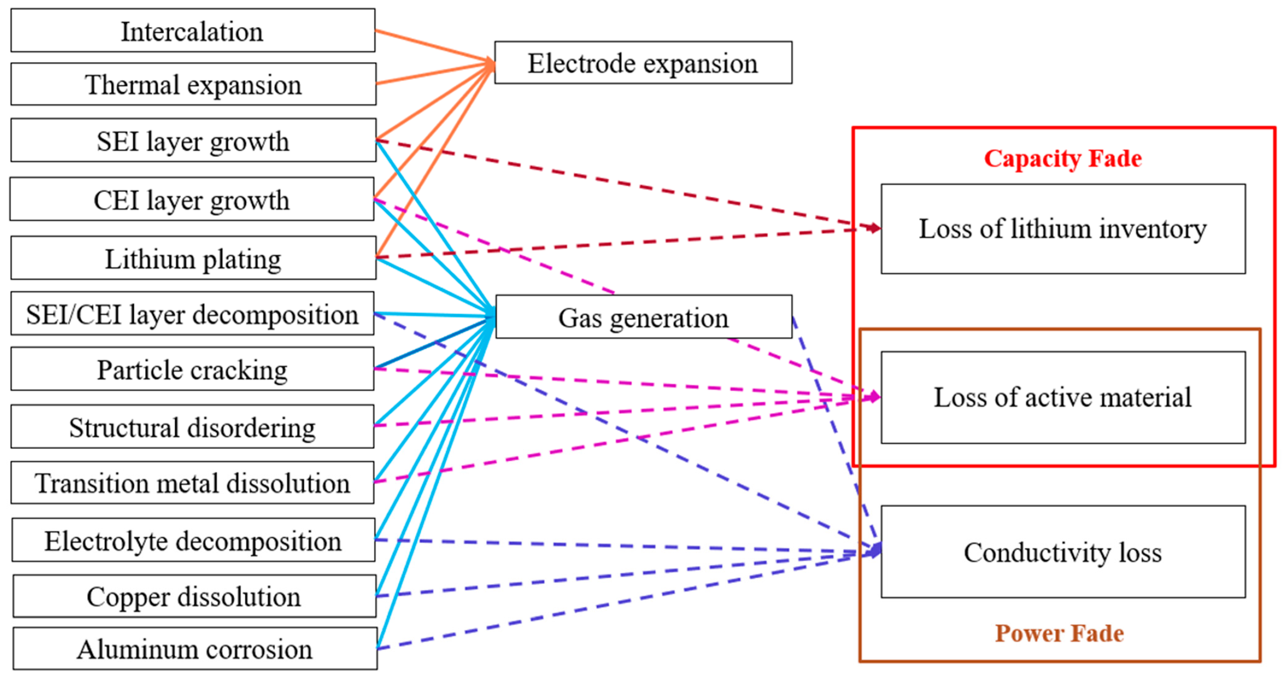
Swelling in LIBs can be reversible or irreversible. In reversible swelling, the battery returns to its near-original dimensions after exposure to operational or environmental stimuli, while for irreversible swelling, the battery continues to expand over time. The mechanisms that result in electrode expansion and gas generation (see Figure 2) are discussed in the following subsections.

2.1. Electrode Expansion

Electrodes in lithium-ion batteries consist of active material coated onto metal current collectors. The anode typically uses graphite as the active material, which is coated on a copper current collector. The cathode uses materials such as lithium manganese oxide (LMO), lithium iron phosphate (LFP), lithium cobalt oxide (LCO), lithium nickel manganese cobalt oxide (NMC), or lithium nickel cobalt aluminum oxide (NCA), coated onto an aluminum current collector [19]. The electrode slurry is prepared by mixing active material with binder and conductive additives, which are coated onto the current collector, dried, and calendared [20].
Electrode expansion refers to the dimensional changes in electrodes during battery operation. These changes arise from several mechanisms, including thermal expansion, lithium intercalation, interphase layer growth, and lithium plating. Thermal expansion and contraction occur due to changes in temperature during cycling or within the ambient temperature in which the battery is stored or operated. Intercalation expansion and contractions result from changes in the lattice structure as lithium ions enter or exit the electrode material [21,22]. The formation and growth of the solid electrolyte interphase (SEI) on the anode and the cathode electrolyte interphase (CEI) on the cathode contribute to increased electrode thickness along with gas generation. Lithium plating occurs due to the deposition of metallic lithium on the anode surface, increasing its thickness. The following subsections examine each of these mechanisms.

2.1.1. Thermal Expansion

Thermal expansion is the tendency of a material to change its volume in response to a change in temperature, quantified by the coefficient of thermal expansion (CTE). In LIBs, this occurs when the cell heats up during charging and operation due to the LIB’s internal resistance or when the battery is placed in an increased ambient temperature condition [23]. Thermal expansion affects all cell components, including electrodes, separator, electrolyte, and casing. The expansion depends on the CTE of each material and how they are attached. Electrode materials, including active material and current collectors, generally have CTEs ranging from 2.1 × 10⁻⁶/°C to 15 × 10−6/°C [24,25,26,27,28] compared to the polymer-based separators having CTEs ranging from 44 × 10−6/°C to 130 × 10−6/°C [29,30]. However, since electrodes are substantially thicker (50–200 µm) compared to separators (20–30 µm), their contribution to overall cell dimensional change is greater. Consequently, the cell stack’s effective or “bulk” thermal expansion depends on the intrinsic CTE of each material and its relative thickness (volume fraction) within the cell. The CTEs of commonly used anodes, cathodes, and separators are listed in Table 1.
Some of the battery components listed in Table 1 exhibit anisotropic thermal expansion, meaning the extent of expansion differs in different directions. Graphite anodes, for instance, expand primarily along the c-axis of the crystal structure because the weak van der Waals forces between layers allow the interlayer spacing to increase with temperature. In contrast, strong covalent bonding within the graphene planes restricts motion, leading to a slight contraction and thus a negative CTE in the in-plane directions [32].
Polymer separators are manufactured through a multi-step process involving melt extrusion, annealing, stretching, and heat fixation, resulting in an orthotropic material with different CTEs in different perpendicular directions [30]. Within the normal operating temperature range of lithium-ion cells (typically −20 °C to 60 °C), thermal expansion of cell components is generally reversible [33]. However, polymers tend to be viscoelastic, and repeated thermal cycling can lead to irreversible expansion as well as mechanical fatigue, microcracking, and delamination at material-to-material interfaces.
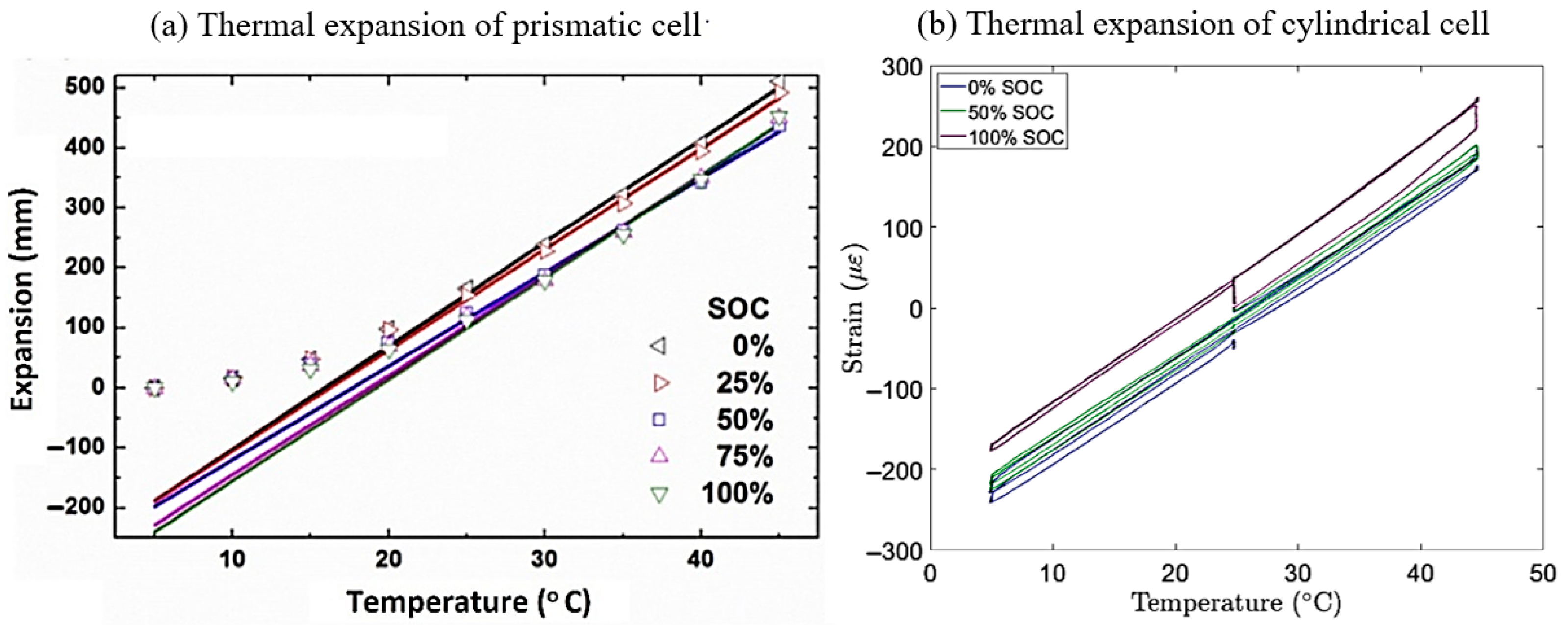
Oh et al. [34] measured expansion at five locations on a 5 Ah NMC–graphite prismatic battery from 5 °C to 45 °C (at 5 °C intervals) and five SoC levels and observed that expansion was highest at the center of the cell. The thermal expansion appeared to be nonlinear from 5 °C to 25 °C and linear from 25 °C to 45 °C, as shown in Figure 3a; however, the authors noted that the observed nonlinearity at lower temperatures results from initial gaps inside the jellyroll that gradually close with increasing temperature, after which expansion becomes linear. Furthermore, the measured CTE matched the values for polyethylene (PE) and polypropylene (PP), suggesting that separator materials dominate thermal expansion. A weak SoC dependence (<10%) was observed, linked to phase transitions in graphite and NMC.
Bezsonov et al. [35] measured hoop strain at the center of an 18,650 NCA-graphite cell across three SoC levels and found thermal expansion to be linear from 5 °C to 45 °C throughout, supporting the idea that the nonlinearity observed by Oh et al. arises from initial internal gaps rather than the intrinsic properties of the cell materials. The similar slopes of the strain–temperature curves across SoC levels further confirm that thermal expansion is largely independent of the state of charge.

2.1.2. Intercalation-Induced Expansion

LIB operation involves the movement of lithium ions between the anode and cathode through the electrolyte. Intercalation refers to the reversible insertion of lithium ions into the layered structure of a host material (anode or cathode active material), while deintercalation involves their removal [36]. During charging and discharging, lithium ions intercalate into and deintercalate from the electrode materials, altering the valence states of the electrodes, resulting in the largely reversible expansion and contraction of the electrode materials.
Atomic-scale structural changes are analyzed using X-ray diffraction (XRD) and neutron diffraction [37,38,39], while electrochemical dilatometry and wafer curvature methods quantify single electrode-level expansion (current collector + active material) [40]. Massoudi et al. [41] conducted an investigation combining dynamic mechanical analysis, thermomechanical analysis, electrochemical dilatometry, acoustic emission monitoring, ultrasonic probing, and stress–strain testing to characterize electrode stiffness, expansion behavior, and structural evolution over cycling. Their results showed that when the battery is subjected to cycling, the initial strain is reversible, but continued cycling causes irreversible changes such as plastic deformation, particle cracking, and cumulative volume increases.
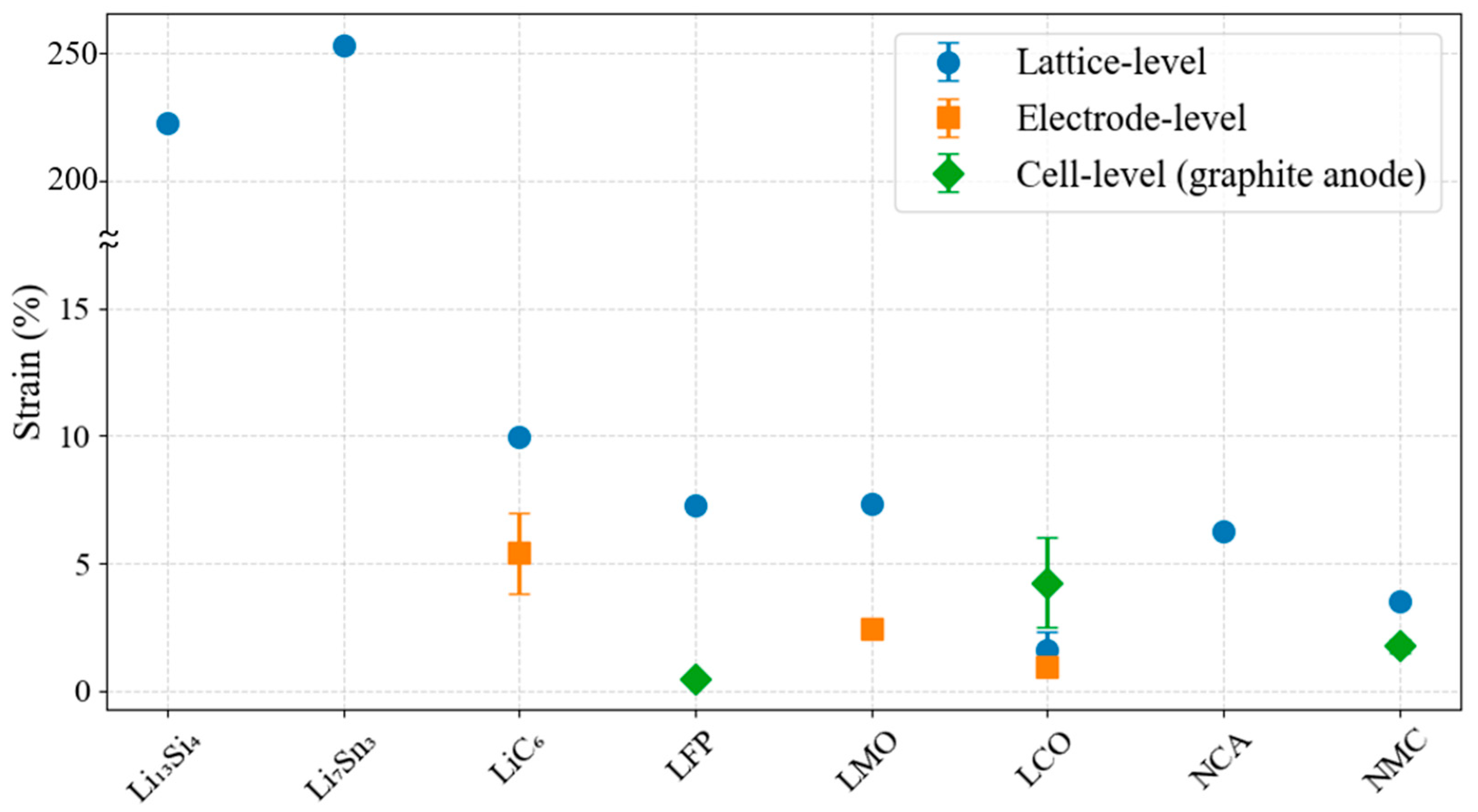
Anode swelling varies with material type. Graphite is the most widely used anode material due to its structural stability, where its layered structure allows lithium to intercalate between graphene planes [42]. Zhang et al. [43] described the lithium intercalation mechanism in graphite, showing that the evolution of stage transitions, structural anisotropy, and stress development during cycling contribute to electrode expansion and long-term capacity fade. Their calculations predicted graphite lattice expansion of ~14% [39], while their experimental measurements reported ~10% in fully lithiated LiC6 [38]. Hahn et al. [44] performed a dilatometric study of graphite electrodes to quantify electrode expansion during lithium intercalation and found that, at the electrode level, the overall swelling is limited to ~3–4%, as the porosity and binder in composite electrodes accommodate a portion of the interlayer lattice expansion.
Silicon-based materials offer higher theoretical capacity (~3579 mAh/g for Li15Si4) than graphite (~372 mAh/g) but undergo up to 300% volume expansion during full lithiation. This amount of expansion generates high internal stress, which can lead to particle fracture, electrical disconnection, and rapid capacity fade [45]. Qian et al. [46] showed that SiOx-based anodes exhibit expansion dependent on SiOx content, with swelling approaching 300% at high loadings (>10%). Reducing silicon content to below 10% and applying a confining layer on top of the electrode can suppress excessive SEI formation and limit volume growth [46]. Silicon is now commonly used in small fractions (5–15%) in commercial anodes [47].
Lithium titanate (Li4Ti5O12, or LTO) is another anode material known for its structural stability [42,48]. LTO operates via a zero-strain mechanism and exhibits negligible volume change during lithiation [49]. Its dimensional stability under cycling makes it suitable for applications requiring long life and high-rate performance, despite its lower capacity (~175 mAh/g).
Cathode materials in LIBs are categorized based on their crystal structure into layered, spinel, and olivine types [50], all of which affect the swelling behavior. Olivine-type LFP supports one-dimensional lithium transport, with up to 7% lattice expansion [38]. Layered oxide cathodes, such as LCO, NMC, and NCA, allow lithium ions to intercalate and deintercalate in a two-dimensional fashion [51,52]. LCO electrodes exhibit relatively low (~1–2%) lattice expansion during cycling [38,53,54]. Reiger et al. [53] found that single-layer LCO cathode expansion is dependent on electrode thickness, with expansion of 0.8% in 50 µm electrodes to 1.74% in 400 µm electrodes. NMC exhibits ~3.5% lattice expansion during the initial charge to 4.2 V, while NCA expands more (~6%) under the same conditions, indicating greater structural distortion and potentially reduced cycling stability [37]. Spinel-type LMO has a cubic structure with three-dimensional lithium transport [55], showing ~7% lattice [38] and ~2.5% electrode expansion [53]. However, it exhibits more mechanical strain during cycling due to the dynamic Jahn–Teller distortion of Mn3+ ions [56].
Stallard et al. [57] reviewed the dimensional changes in cathode materials that occur during lithiation and delithiation, highlighting that these volume changes are strongly anisotropic in layered materials (e.g., NMC, LCO) but more isotropic in spinels. They linked lattice-level dimensional changes to particle-scale swelling and strain heterogeneity, showing that misaligned grains within cathode particles expand differently. This differential expansion generates stress concentrations at grain boundaries, promoting intergranular cracking and microfracture, which progressively degrades the cathode’s mechanical integrity. The resulting mechanical degradation manifests as reductions in Young’s modulus, hardness, and fracture strength with cycling, and leads to loss of active material connectivity, ultimately reducing electrochemical performance.
Cell-level swelling pertains to the expansion of all the internal components as well as the casing, and is a function of the cell architecture, the SoC, C-rate, temperature, and cycle history. It is measured by monitoring cell thickness/strain using micrometers, optical displacement sensors, or in situ X-ray imaging. Wang et al. [58] investigated a commercial LCO–graphite cell using load cell measurements and in situ X-ray imaging during cycling at 1C and 2C rates. They observed that volume changes became more pronounced at higher C-rates (>1C), especially in the near-surface regions of the active material particles. This behavior was attributed to limited lithium diffusion, which causes lithium to accumulate near the particle surface, leading to localized lattice expansion before the core can fully equilibrate.
Sauerteig et al. [59] developed an electrochemical–mechanical model to investigate how internal pressures evolve during cycling in a 10 Ah NMC–graphite hard-case cell. Their simulations showed that electrode volume changes in the range of 2–4% generate significant mechanical stress within and between electrode layers, influencing local ionic transport at the electrode–separator interfaces. The model revealed that these stresses can cause heterogeneous strain distributions across the electrode thickness, potentially affecting the mechanical integrity of the cell and leading to localized performance degradation over repeated cycles.
Wunsch et al. [60] measured SoC-dependent thickness variations in aged NMC pouch cells and reported expansions in the range of 1.5–2%. These results were supported by Zhao et al. [61], who observed comparable swelling in NMC–graphite cells under operational conditions. Lee et al. [62] found reversible 2% swelling during cycling of cells composed of graphite anodes and layered lithium transition metal oxide cathodes.
Figure 4 summarizes the lithiation-induced expansion across the lattice, electrode, and cell levels for different active material combinations. Among the chemistries compared, LCO–graphite cells showed the highest cell-level expansion (~6%) due to minimal contraction in the LCO cathode, whereas LFP–graphite cells exhibited the least (~0.5%), consistent with LFP’s low lattice expansion and structural rigidity [58,63].
Cell expansion during lithiation is anisotropic. Mechanical constraints imposed by current collectors and polymeric binders restrict deformation within the electrode plane (xy), resulting in preferential expansion in the out-of-plane (z) direction. Rieger et al. [53] conducted XRD, single-electrode dilatometry, and cell-level displacement measurements for LCO cathodes and reported lattice-level volumetric expansion of 2.32% upon full lithiation. However, the electrode-level thickness increase was only 1.74 to 1.86. Measurements showed in-plane (x-axis) expansion of 0.12%, compared to an out-of-plane (z-axis) expansion of 2.5%. Similarly, in graphite anodes, the interlayer spacing expands by ~10% during full lithiation, whereas basal plane dimensions increase by only ~1% [38].

2.1.3. Electrode-Electrolyte Interphase Layer Formation and Growth

The formation and growth of electrode-electrolyte interphase layers, specifically the SEI on the anode and the CEI on the cathode, contribute significantly to electrode swelling during early cycling and long-term aging. These interphases act as kinetic barriers that regulate ion transport while preventing continuous electrolyte decomposition. A stable and uniform SEI minimizes parasitic reactions, reduces impedance growth, and enhances Coulombic efficiency, while an unstable or resistive SEI leads to lithium consumption, capacity fade, and dendrite formation, increasing the risk of short circuits and thermal runaway. Similarly, the CEI influences transition metal dissolution and cathode surface degradation, especially at high operating voltages (typically >4.2 V vs. Li/Li+). Variations in the composition, thickness, and morphology of these layers under different cycling and thermal conditions directly impact gas generation as well.
The SEI forms on the anode via electrolyte reduction and typically reaches 10–50 nm in thickness [66]. Hahn et al. and Sauerteig et al. showed that SEI formation accounts for ~3.5–4% irreversible expansion during the first cycle [44,65]. SEI growth continues with cycling due to cracking, regrowth, and stress buildup, especially at high currents and elevated temperatures [67]. In silicon-based anodes, SEI thickness can increase from 22 to 72 nm between the first and eleventh cycle [68], and in SiOx/graphite composites, SEI layers can grow from 100 to 300 nm [69,70], contributing significantly to volume expansion and mechanical degradation. Zang et al. demonstrated that SEI swells in contact with electrolyte and thickens with aging, indicating continued electrolyte uptake and reduced transport properties [71].
Electrolyte additives such as fluoroethylene carbonate (FEC) and vinylene carbonate (VC) have been shown to effectively engineer stable interphases on high-capacity electrodes, suppressing continuous electrolyte decomposition and mitigating electrode swelling [72]. Specifically, FEC improves the cycling stability of nano-silicon anodes [73] and Si–C composite anodes [74] by forming a protective SEI that reduces swelling-induced degradation, whereas VC enhances rate capability but provides less suppression of swelling [73].
Formation protocols using low current densities can further improve SEI uniformity and limit electrode expansion [75,76], though they may increase manufacturing costs [77]. Empirical studies by Ota et al. [78] demonstrated that SEI growth follows a diffusion-limited process, generally scaling linearly with the square root of time across a range of current densities. These experiments were conducted at room temperature to isolate concentration-dependent effects, minimizing thermal gradients or viscosity changes that could influence the results.
Jha et al. [79] showed by modeling that SEI thickness can vary between 50 and 500 nm by 2000 cycles, depending on the anode particle size, reaction rate constants, discharge rate, and cell voltage. Smaller anode particles and higher reaction rate constants result in thinner SEI films and reduced film resistance due to faster lithium transport. Conversely, higher C-rates and elevated cell potentials accelerate SEI growth, increasing both film thickness and resistance [79]. These insights highlight the need for careful optimization of electrochemical and material parameters to control SEI evolution and minimize long-term degradation.
The CEI layer forms on the cathode via oxidative decomposition of salts and solvents [80]. The CEI layer consists of inorganic-rich and organic-rich layers that passivate the surface but contribute to volumetric changes. Neutron reflectometry has revealed CEI thickness increases from ~35.6 nm (discharged) to ~48.8 nm (charged) on LCO cathodes, suggesting ~37% volumetric expansion of the cathode due to CEI evolution [81]. Bonefacino et al. [82] used fiber Bragg grating (FBG) sensors to measure in situ strain in LFP–LTO coin cells during cycling and observed irreversible strain buildup during the first 20 cycles. The irreversible strain increased to around 5% before stabilizing, which was attributed to CEI formation, as SEI formation is not expected on the LTO anode. Over prolonged cycling, non-uniform CEI can delaminate and re-form, creating a continuous electrolyte consumption loop and contributing to capacity fade [81]. CEI thickness and stability are influenced by moisture, voltage limits, and electrolyte composition, with additives like lithium bis-(oxalate)borate (LiBOB) or fluorinated solvents helping suppress excessive growth [80,81,83]. Together, SEI and CEI evolution drives irreversible volume increases and contributes to performance degradation through coupled electrochemical–mechanical effects.

2.1.4. Lithium Plating

Lithium plating occurs when lithium ions deposit as metallic lithium on the anode surface instead of intercalating into graphite. This happens when the anode potential falls below 0 V vs. Li/Li+, meaning the anode is locally “overcharged” and lithium prefers to plate as metal. Such a drop in potential is typically caused by polarization (voltage losses due to Ohmic resistance in the cell), slow charge transfer kinetics at the electrode–electrolyte interface, or limited lithium diffusion within the electrode or electrolyte [84,85]. Plating often occurs alongside intercalation during fast charging or at low temperatures, where lithium transport is kinetically limited [86].
Plated lithium occupies more volume than intercalated lithium (~0.37 cm3 per Ah), directly contributing to local electrode swelling and increased internal stress. This expansion exacerbates SEI growth, forms unstable surface layers, and creates dead lithium regions, reducing both mechanical integrity and electrochemical performance [84,86,87]. Lithium plating-induced swelling is influenced by high state-of-charge, elevated charging rates (>1C), low ambient temperatures [84], electrode imbalance [88], and structural features such as porosity and tortuosity [89,90]. Applying appropriate stacking pressure can reduce localized plating, limit swelling heterogeneity, and promote more uniform mechanical and electrochemical aging [91,92,93]
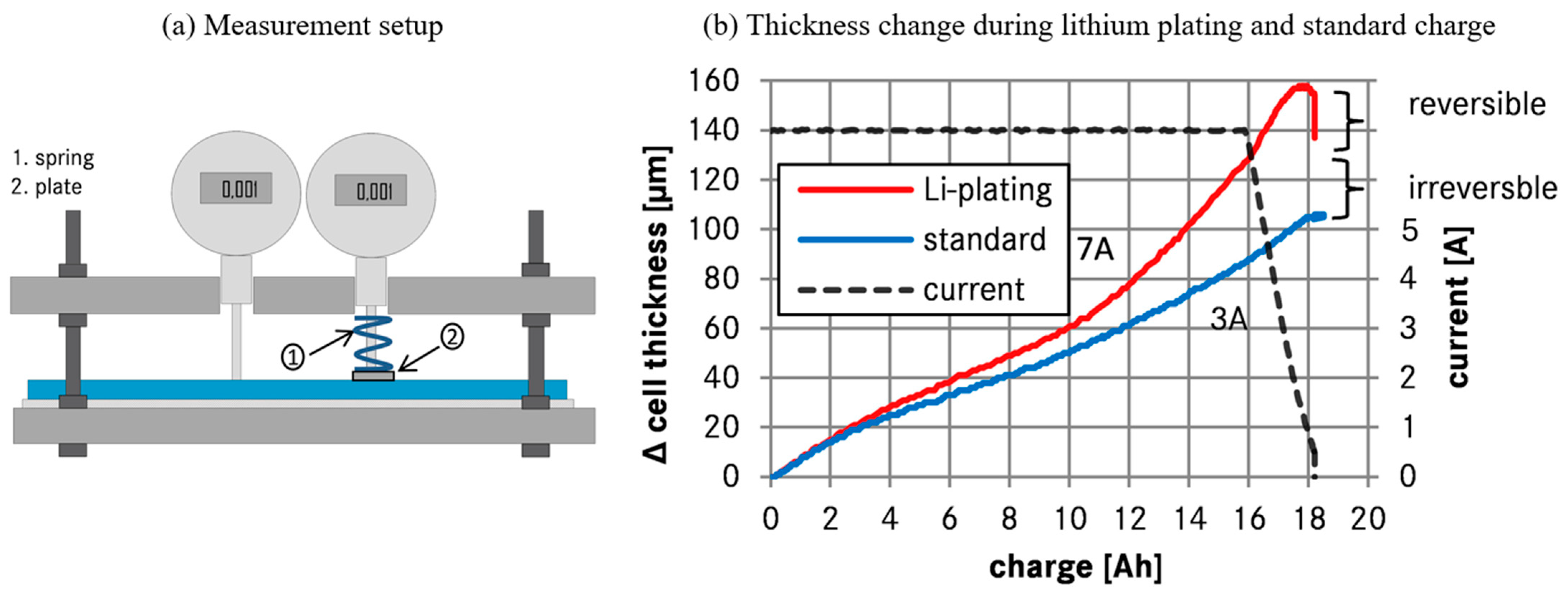
Bitzer et al. [5] investigated lithium plating in 20 Ah Li-ion pouch cells (graphite anode, NMC cathode) by tracking cell thickness using two high-precision dial indicators in a temperature-controlled setup (Figure 5a). Cell thickness refers to the physical distance between the two outer surfaces of a pouch cell, measured perpendicular to the electrode stack. The cell was mounted between fixed plates in a temperature-controlled chamber, where one of the indicators had a spring applying ~2 bar to distinguish mechanical compression effects from true volume expansion. At low current charging (2.5–4.5 A) and −5 °C, the thickness changes matched the expected intercalation behavior, with no difference between the two indicators, indicating no gas evolution. In contrast, at higher current (14A) and the same temperature, a marked and partly irreversible increase in thickness was observed, especially at the uncompressed point, as shown in Figure 5b. This suggests lithium plating, which deposits metallic lithium on the anode surface, occupying more volume than intercalated lithium (approx. 0.37 cm3 per Ah plated, or ~16.1 µm increase in thickness per Ah for their cell size). The additional swelling was attributed to both irreversible lithium and gas evolution from side reactions. This behavior highlights that swelling during charging is not fully reversible, with the residual swelling serving as an indicator of cumulative lithium plating and associated degradation.
Bauer et al. [94] reported similar findings to Bitzer et al. [5], with a decrease in cell thickness after charging at −5 °C, which was attributed to the chemical intercalation of plated lithium. Rieger et al. [95] found localized thickness increases near the current collector tab during fast charging at 17 °C. Grimsmann et al. [96] confirmed these effects using 10 nm resolution displacement measurements. Spingler et al. [97] linked localized anode expansion to lithium plating by tracking NMC pouch cell thickness during cycling using laser triangulation. They found that irreversible expansion averaged 5.2% and correlated with voltage relaxation and capacity fade.
Lithium plating-induced swelling overlaps with other contributions to electrode expansion, including intercalation strain, SEI growth, and gas evolution [84]. Therefore, changes in cell thickness should be interpreted as the combined result of these mechanisms rather than solely due to plating. Complementary techniques such as voltage relaxation analysis, differential voltage analysis [97,98,99], incremental capacity analysis, coulombic efficiency [100,101], and electrochemical impedance spectroscopy (EIS) [87] can help separate the contributions of plating from other sources of swelling. Irreversible thickness increases observed during cycling provide a measure of cumulative electrode expansion and associated mechanical changes. Non-destructive, spatially resolved methods such as ultrasound acoustic measurements [102] can identify localized regions of expansion. Measurements of cell thickness, including irreversible increases cycling and localized expansions detected by ultrasound, provide a direct assessment of electrode-level swelling and its spatial distribution, capturing the combined effects of lithium plating, intercalation strain, SEI growth, and gas evolution.

2.2. Gas Generation

Gas generation in LIBs begins during the formation cycle and continues throughout the life of the cell. During the formation stage, gas evolution is dominated by electrolyte reduction at the anode during SEI formation. Establishing a stable and electronically insulating SEI is essential to limit further electrolyte decomposition and to minimize gas production in subsequent cycles [103]. Leibing et al. [104] showed that formation at low C-rates (e.g., 0.1C) resulted in minimal gas evolution and reduced swelling in NMC–graphite cells. Wang et al. [105] identified CO2, CO, and C2H4 as the dominant gases formed during initial charging. In pouch cells, excess gas is removed during formation through a degassing step before final sealing. In contrast, cylindrical and prismatic formats do not undergo degassing, resulting in a sealed system with elevated internal pressure due to retained gases [20].
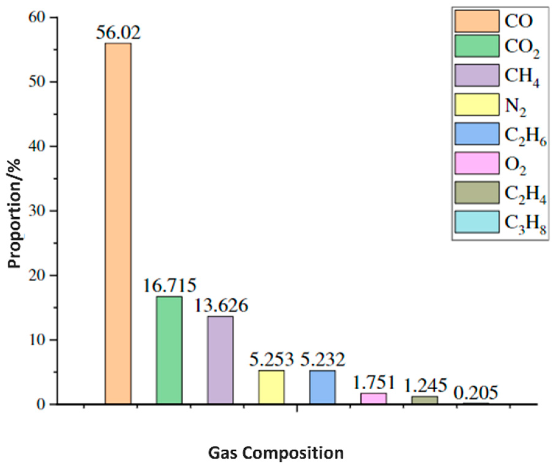
The battery swelling during charge/discharge and storage can result from gas generation, generally due to the chemical oxidation and redox decomposition of the electrolyte solvents on the anode and cathode [106]. Figure 6 illustrates the eight types of chemical constituents that were identified by gas chromatography in an NMC–graphite cell after overcharge. CO was the dominant component, accounting for about 56% of the total gases found, CO2 represented 16%, and CH4 represented 13% [107]. As the cell continues to cycle, gas generation increases due to electrolyte decomposition, electrode-electrolyte interphase reactions, and cathode degradation. The generation of these gases is directly correlated with both temperature and voltage. The gases can include flammable and reactive species such as hydrogen, ethylene, carbon monoxide, carbon dioxide, and oxygen, leading to degradation of performance parameters such as capacity retention and impedance, and safety hazards [108,109]. The following subsections detail the specific sources and mechanisms of gas generation in LIBs.

2.2.1. Gases Generated at the Anode

Graphite anodes are particularly prone to gas evolution due to electrolyte reduction, especially during the initial charge–discharge cycles. Ethylene (C2H4) is primarily produced from the reduction in EC at around 0.8 V vs. Li/Li+, peaking at 0.5 V in EC/EMC electrolytes [44,108,110]. Lithium ethylene dicarbonate (LEDC) and Li2CO3 are key products of these reactions, contributing to the SEI [110,111]. Water contamination, even at low ppm levels, is a major source of hydrogen evolution due to water reduction at the anode surface [111,112]. Any hydroxide ions generated can further catalyze electrolyte decomposition and hydrolysis reactions with EC [113,114].
Although LTO is often termed a “zero-strain” anode due to negligible electrode expansion [115], gas evolution can still lead to swelling and pressure build-up. LTO anodes, operating at 1.55 V vs. Li/Li+, lie within the electrolyte stability window and avoid initial SEI formation [116] but exhibit significant hydrogen evolution during storage, due to water reduction at potentials up to 2 V [114,115]. LTO can also catalyze dehydrogenation and decarboxylation of electrolyte solvents, producing H2 and CO [117,118].
SEI breakdown at elevated temperatures and poor SEI quality in the presence of moisture can exacerbate gas evolution. The use of additives like VC can mitigate some of this gas generation [44]. Under over-discharge or local short-circuits, copper from the anode current collector can dissolve and deposit on the cathode [119]. This copper can catalyze additional electrolyte decomposition reactions, resulting in increased gas generation, especially CO2 and C2H4 [120]. The gases generated at the anode occupy additional volume within the cell, contributing directly to cell-level swelling.

2.2.2. Gases Generated at the Cathode

At the cathode, particularly for nickel-rich NMC materials, gas evolution arises from both electrochemical oxidation of the electrolyte and surface contaminants like Li2CO3. Decomposition of surface Li2CO3 begins at ~3.8 V and produces CO2 and singlet oxygen (1O2) [121]. Renfrew et al. [122] and Mahne et al. [123] showed that residual Li2CO3 on both Li-stoichiometric and Li-rich layered oxides is the dominant source of CO2 and CO outgassing in the first cycle, linking surface contamination directly to gas evolution.
Jung et al. [124] found that oxygen release from Ni-rich NMC cathodes at high states of charge of the cell destabilizes the surface and accelerates electrolyte decomposition. Wandt et al. [125] demonstrated that layered transition-metal oxides evolve singlet oxygen during cycling, which drives parasitic electrolyte oxidation. Streich et al. [126] observed that Ni-mediated surface reconstruction in Ni-rich NMC begins very early in cycling, creating reactive sites that promote electrolyte decomposition. Oxygen evolution becomes significant at >80% SoC of the cell and correlates with Ni content in the NMC lattice [127]. Electrochemical oxidation of conductive carbon and PVDF binder at high voltages (>4.5 V) also contributes to CO and CO2 production [128,129]. Electrolyte salt degradation due to hydrolysis of LiPF6 in the presence of ROH and moisture produces POF3 and HF, further exacerbating gas evolution [130,131,132].
The dissolution of transition metals (e.g., Ni, Mn, Co) from NMC cathodes into the electrolyte and subsequent migration to the anode can degrade the SEI and increase parasitic reactions, particularly under high voltage or high temperature cycling [133]. Corrosion of the aluminum current collector at the cathode can also contribute to gas generation [120]. At high potentials (>4.2 V), especially in the presence of HF formed from LiPF6 hydrolysis, Al3+ ions are released. This dissolution process catalyzes electrolyte decomposition and promotes hydrogen and CO2 evolution [134].
Cracking secondary particles in high-Ni layered oxides (e.g., NMC811) during cycling exposes fresh surfaces that are highly reactive to electrolyte solvents. This increases oxygen release and accelerates gas-generating side reactions, particularly with EC and EMC, producing O2, CO2, and CO [132]. The continuous formation of reactive surfaces through particle fracture also enhances the dissolution of transition metals, further exacerbating degradation and gas evolution [132]. Washing cathodes before cycling has proven effective in reducing initial gas evolution by removing surface Li2CO3 [135]. Cathode materials like LFP are more stable and show minimal gas evolution due to their resistance to gas-generating reactions [130].

2.2.3. Electrolyte Decomposition

Electrolyte decomposition contributes substantially to gas generation through electrochemical and chemical oxidation pathways. Electrochemical oxidation depends on the cell potential and electrode surface area, with conductive carbon playing a critical role due to its high surface area [136]. Chemical oxidation, on the other hand, results from reactive species including singlet oxygen released from cathodes, particularly NMC, which can attack carbonate solvents [114]. The decomposition of EC can produce CO, CO2, and/or C2H4, depending on the reaction pathway and cell potential [118,137,138].

2.2.4. Crosstalk and Gas Consumption

Inter-electrode reactions, or “cross-talk,” alter gas dynamics by enabling the consumption of gases formed at opposing electrodes [139,140]. Xiong et al. [140] showed that high-temperature and high-voltage operation intensifies crosstalk between positive and negative electrodes, leading to accelerated electrolyte oxidation, gas generation, and impedance growth. One example is the consumption of CO2 at lithiated graphite anodes to form lithium oxalate (Li2C2O4), especially at potentials below 2.8 V vs. Li/Li+ [13,141].
Sloop et al. [142] showed that reactive electrolyte decomposition products generated at the cathode can migrate to the anode, where they undergo further reduction; this crosstalk between electrodes drives parasitic reactions, accelerates self-discharge, and contributes to gas evolution. Similarly, CO2 can be consumed to form carbon deposits on lithium electrodes. Hydrogen can also be consumed electrochemically to form lithium hydride (LiH) [143]. This process is temperature-sensitive and more prominent above 60 °C. Ethylene is known to be consumed at charged graphite anodes [144]. Finally, CO is thought to react with residual moisture to form H2 and CO2 during long-term storage [143].
Transition metal dissolution from the cathode, especially in cells using LNMO or NMC, can promote SEI degradation at the anode, leading to gas generation [133]. Self et al. [145] found that CO2 forms at the cathode from electrolyte oxidation and is absorbed by the graphite anode, while anode-side reductions produce C2H4 and CH4. Lee et al. [2] found that side products from the lithium metal anode, including HF and organic decomposition compounds, migrated through the separator and deposited on the cathode, forming a thick and resistive CEI. They observed that the poly(vinylidene fluoride) co-polymer binder (PVDF-HFP) in the separator swelled, creating defects that allowed the soluble species to pass through. These inter-electrode interactions not only influence the overall gas composition within the cell but also accelerate degradation through cross-contamination and interphase instability.
The primary gases identified across LIB systems include: CO and CO2, generated during the initial charge as a result of SEI formation on graphite and during oxidation at high potentials when the electrolyte is being decomposed at the cathode side [133,146]; C2H4, formed during SEI formation [147]; H2, formed through the reduction in water impurities [148]; and O2, formed at high potentials, especially from lithium-rich transition metal oxides [105,149]. The major reaction pathways identified at the cathode and anode are summarized in Table 2. The volume expansion associated with gas generation in the presence of repeated cracking and thickening of the SEI layer leads to irreversible expansion, which can be as high as 50% of the cell volume [150]. While initial gas evolution during formation can be addressed through degassing, long-term gas management requires careful control of material purity, electrolyte composition, electrode formulation, and chemistry-dependent operating and environmental conditions.

3. Factors Affecting Swelling

Swelling in lithium-ion cells arises from both reversible and irreversible processes. While intercalation causes reversible expansion, long-term dimensional growth is driven by irreversible mechanisms such as SEI thickening, lithium metal plating, and gas accumulation. Swelling behavior is strongly influenced by cell chemistry, electrode structure (e.g., porosity, tortuosity), electrolyte composition, and manufacturing quality, particularly moisture control and contamination avoidance. Operational factors such as C-rate, temperature, voltage, and SoC determine the severity and onset of the degradation pathways causing swelling. Each condition promotes specific failure mechanisms, including lithium plating, SEI growth, and gas evolution, which collectively drive irreversible swelling. The following sections discuss the factors that contribute to this irreversible expansion.

3.1. Effect of C-Rate on Swelling

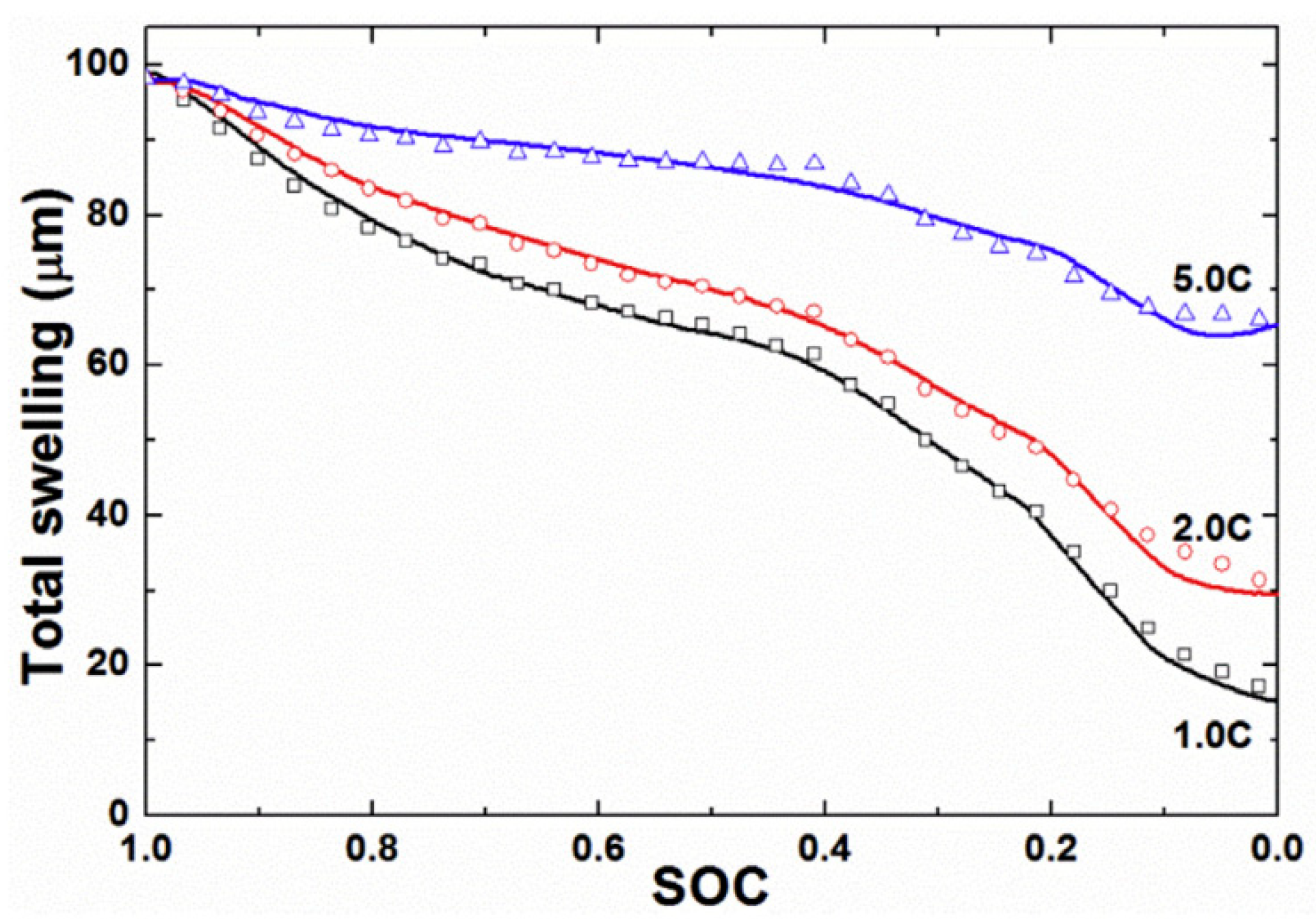
Swelling in LIBs increases with increasing C-rates due to Joule heating, which causes thermal expansion, and due to kinetic/electrochemical effects, including lithium plating and gas generation. Oh et al. [23] used in situ dilatometry on a 5 Ah NMC/graphite prismatic cell to track thickness changes at various C-rates. At C/25, ~1.5% reversible expansion was observed, consistent with intercalation. At high C-rate (5C), an additional residual increase in cell thickness persisted after discharge (see Figure 7). Thus, while higher C-rates induce both reversible thermal and intercalation expansion, the persistent thickness increase highlights irreversible swelling.
Seigel et al. [62] used in situ neutron imaging during C/5 and 5C cycling of LFP/graphite pouch cells. At low C-rates, neutron imaging showed that expansion follows the staging behavior of lithium intercalation in graphite, with a saturation region above ~40% SoC where little additional swelling occurs. This behavior reflects the phase transitions in the graphite anode during lithium intercalation. However, at higher C-rates, the relationship changed, where swelling increased linearly across the entire SoC range. As the cells aged at high C-rate (2C), an irreversible expansion of 1.5% was observed with a reduction of 4% capacity.
Dai et al. [155] cycled LFP pouch cells at 30 °C over a voltage range of 3–4 V at 0.2C, 0.5C, 1C, and 4C for 200–800 cycles. After 800 cycles at 1C, the graphite electrode exhibited approximately 20–30% expansion. This expansion was attributed to the formation of voids within the graphite particles, leading to a ~10% increase in particle diameter.
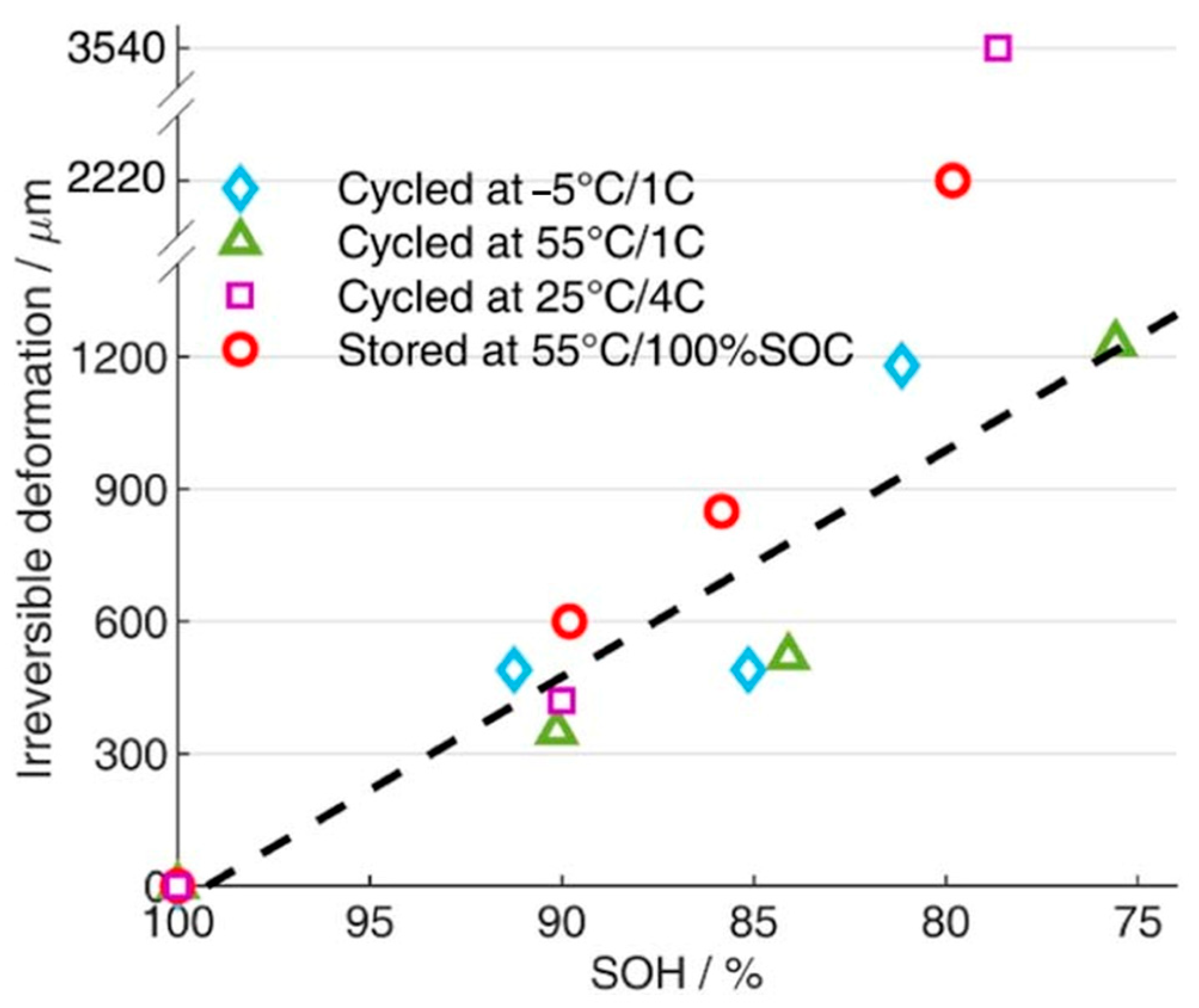
Li et al. [150] investigated the effects of C-rate and temperature on long-term irreversible swelling in large-format NMC/graphite pouch cells. At approximately 79% state of health (SoH), the battery cycled at 4C charge/1.5C discharge at 25 °C exhibited a thickness increase of 3540 μm, which corresponds to 45.3% of its original thickness (7720 μm) as shown in Figure 8. SEM revealed dense deposits on the anode from electrolyte decomposition and SEI growth. Incremental capacity analysis showed lithium intercalation peaks faded significantly, confirming lithium loss. This degradation mechanism resulted in a nonlinear increase in irreversible deformation that was disproportionately large below 80% SoH. Szürke et al. [156] evaluated polymer LIBs at 1C, 1.5C, and 2C using displacement sensors. Their results revealed that there is a rise in swelling magnitude as the C-rate is increased, with a swelling of 22% observed at a 2C rate.

3.2. Effect of Temperature on Swelling

Temperature impacts swelling via both intrinsic thermal expansion of internal components and temperature-dependent electrochemical degradation. While uniform heating causes recoverable expansion of electrodes, separators, and current collectors, irreversible swelling also occurs, especially at elevated temperatures (≥45 °C) due to SEI growth, electrolyte decomposition, and gas generation.
He et al. [157] used in situ pressure measurements and open cell configurations to detect H2, C2H4, and CO2 in LTO cells at 50 °C, with H2 evolving during the first charge and C2H4 from EC reduction at lower potentials. Wu et al. [118] observed that gas generation in LTO cells held at 80 °C for 120 h originated from solvent decomposition, which was anode-potential driven. Belharouak et al. [151] aged LTO–LMO cells at 30–60 °C for 5 months and observed increasing gas generation (H2, CO2, CH4, C2H6) with temperature. Kim et al. [158] studied NMC, NCA, and LCO pouch cells stored at 60 °C and 85 °C. Ni-rich cathodes released most of their gas early during storage, leading to a rapid increase in internal pressure and cell swelling. In contrast, LCO released gas more slowly and continuously over time, resulting in a gradual rise in pressure and more controlled swelling. This slower gas evolution reduces mechanical stress on the electrodes and cell components, making LCO cells more favorable for long-term storage.
Mohtat et al. [8] investigated the impact of temperature on irreversible swelling in NMC–graphite pouch cells. Cycling at 55 °C/1C caused ~16% irreversible deformation at a SoH of 76%, primarily due to cathode-related degradation such as loss of active material and CEI growth. Storage at 55 °C and 100% state of charge (SoC) led to substantially higher expansion (~29% at 80% SoH over 180 days), driven by gas generation from thermal decomposition of the electrolyte, with SEM imaging confirming the absence of solid deposits. Cells aged at 45 °C also exhibited greater irreversible thickness growth compared to 25 °C, even though intercalation-induced strain per cycle was similar as shown in Figure 9. These results indicate that higher temperatures accelerate swelling, mainly through accelerated chemical and electrochemical degradation and increased gas formation within the cell.
Low temperatures, while reducing gas formation, introduce the risk of lithium plating. Chen et al. [159] used 2D/3D X-ray CT and micro-zone analysis to show that charging at 0 °C promotes Li plating, leading to irreversible swelling due to electrode deformation, delamination, and dendrite formation. Mohtat et al. [8] found that cells cycled at −5 °C showed higher irreversible expansion per cycle than those at 25 °C, which is consistent with plating-induced swelling. Li et al. [150] found that at low temperatures, cells cycled at −5 °C/1C exhibited 15% irreversible swelling at 81% SoH. This deformation was primarily attributed to lithium plating on the anode, as confirmed by SEM images showing mossy lithium deposits. Mild gas generation from side reactions between plated lithium and the electrolyte further contributes to irreversible swelling by increasing cell thickness and internal pressure.

3.3. Effect of Voltage and SoC on Swelling

When operated within the nominal voltage range, gas generation in LIBs is generally minimal and attributed to ester exchange reactions in the electrolyte [160]. However, overcharging or over-discharging can significantly accelerate gas formation, triggering pronounced swelling.
During overcharge, increased delithiation of the cathode and lithiation of the anode initiate a three-stage swelling mechanism: a steady voltage rise beyond nominal levels, decomposition of active materials and electrolyte, and eventual structural collapse of electrodes, accompanied by elevated temperatures and side reactions [97]. Mao et al. [161] and Yuan et al. [162] showed that NMC–graphite cells charged above 4.2 V showed a 40% volume increase. These increases are attributed to electrolyte decomposition and gas evolution (e.g., H2, CH4, CO2) [4,162]. Sun et al. [163] reported volumetric expansion up to 277.6% in LFP modules, where lithium plating and thermal breakdown of the SEI layer caused deformation even below 60 °C. Kong et al. [152] found that the extent of gas generation and swelling is also influenced by cathode oxidation capability, with LCO > LMO > LFP.
Over-discharge promotes gas evolution through reduction reactions and dissolution of the copper current collector. In LCO cells, copper migration and re-deposition on the cathode reduce intercalation efficiency and contribute to swelling [164]. Structural SEI changes during over-discharge further release gases such as H2, including CxHy and COz molecules, with hydrogen traced to cathode-originated reactions [165].
Swelling is also strongly SoC-dependent. Neutron imaging and X-ray radiography during C/5 charge–discharge of LFP/graphite pouch cell showed linear swelling from 0 to 30% SoC due to initial intercalation, a plateau between 30 and 70%, and a second expansion phase above 70% as lithium staging progresses in graphite [62]. Fahy et al. [166] demonstrated that swelling magnitude varies with SoC, C-rate, and cell age, with high SoC promoting irreversible electrode deformation. Read et al. [167] observed LiF formation in the cathode during discharge, affecting cathode swelling, while Lu et al. [168] reported greater swelling in LFP-graphite cells stored at 0% SoC due to SEI instability, recommending 30% SoC for safer storage. Lawder et al. [169] used a physics-based pseudo-two-dimensional (P2D) model to show that SEI growth during high-voltage charging and shallow cycling at high SoC accelerates capacity fade and swelling.

4. Relationship Between Swelling and Cell Performance

Swelling in lithium-ion batteries is closely linked to the degradation pathways that occur during cycling and storage. Lin et al. [100] and Juarez-Robles et al. [170] have shown that electrode expansion is interconnected with loss of active material, electrical conductivity, and lithium inventory, which arise from processes such as lithium plating, dendrite formation, SEI growth, and structural decomposition of electrode materials [100,170]. Sauerteig et al. [63] highlighted the connection between swelling and active material loss, stemming from crystal structure changes, electrolyte oxidation, and electrode decomposition. Xing et al. [171] revealed that the loss of conductivity is attributed to the current collector corrosion and binder decomposition, which can contribute to capacity loss and swelling. Li et al. [9] examined the impact of electrode sheet number on swelling force, showing that higher sheet count accelerates swelling and leads to capacity decay.
Swelling also exacerbates the rise in internal resistance. Gas pockets and thicker SEI layers slow down the ion flow between electrodes. Stravová et al. [172] reported that after long-term cycling, the cell’s series resistance roughly doubled (from 81 mΩ to 167 mΩ). Corresponding CT scans revealed 29% swelling in cell thickness, highlighting the coupling between swelling and electrochemical impedance growth. The simultaneous rise in resistance and swelling was attributed to electrolyte breakdown (producing SEI and gas), lithium deposition on the anode, and electrode delamination, all of which increase charge-transfer resistance and mechanical degradation.
The amount and rate of swelling can be used as a diagnostic metric, as it is linked to the internal electrochemical and mechanical state of a LIB cell. For example, it is known that the reversible swelling during charge and discharge cycles corresponds to the SoC [8]. Hendricks et al. [173] installed strain gauges on prismatic cells and trained a neural network on the data to map strain signals to depth-of-discharge, and found that the nonlinear strain response during dynamic discharge could be used to track the SoC.
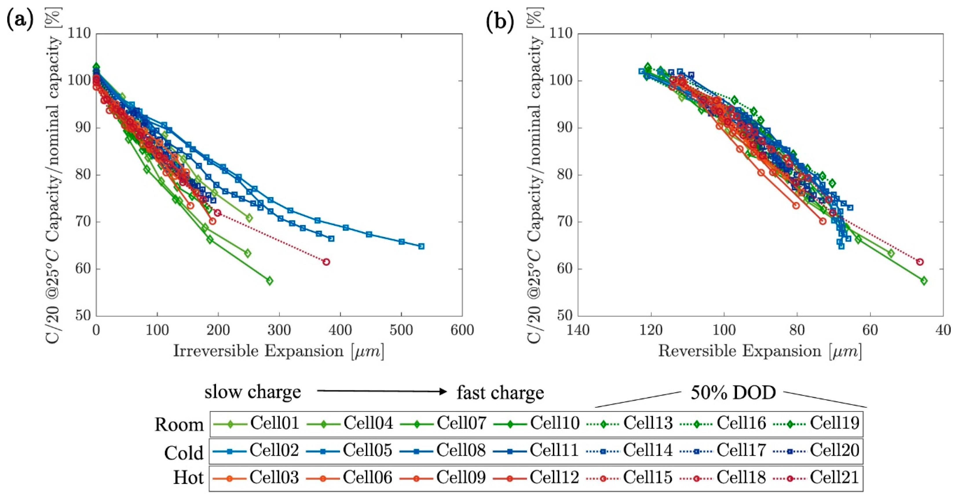
Mohtat et al. [8] monitored thickness changes operando in pouch cells under external load and showed that both the shape and magnitude of the reversible expansion curve evolved with cycling, directly reflecting changes in the anode, cathode, and lithium inventory. By combining expansion data with electrochemical measurements, they were able to separate electrode-specific degradation contributions and estimate key health metrics. The amplitude of reversible expansion per cycle proved to be a sensitive indicator of aging, as its decline reflected the loss of cyclable lithium; with reduced lithium intercalation, the associated volume changes became progressively smaller. In contrast, cumulative irreversible expansion exhibited a linear correlation with capacity fade.
Peng et al. [174] analyzed peak-strain patterns to estimate capacity fade and demonstrated that features of the strain curve can be used to predict capacity degradation. Similarly, Zeng et al. [175] employed the relationship between swelling and underlying degradation mechanisms as prognostic and diagnostic inputs. Swelling measurements have also been applied to detect anomalies such as battery health degradation [11], lithium plating [99], internal short circuits [176], and manufacturing-induced inhomogeneities [64].
Jiang et al. [177] evaluated mechanical measurement techniques for capturing real-time electro-chemo-mechanical behavior in battery electrodes. Their study demonstrated that multi-beam optical stress sensors, digital image correlation, and bending curvature measurement systems can be used to track stress evolution, deformation, and stiffness variations during cycling. These methods were found to provide sufficient spatial and temporal resolution for detecting early indicators of interfacial delamination, internal stress accumulation, and mechanical degradation.
Thermal runaway events trigger the decomposition of electrolytes, which release volatile compounds including carbon dioxide, carbon monoxide, and various hydrocarbons [178]. The breakdown of the SEI layer adds to the gas release, including hydrogen and other hydrocarbons. Additionally, the thermal decomposition of organic solvents in the electrolyte generates gases such as hydrogen, methane, ethane, and propane. As gases accumulate, the internal pressure within the battery rises rapidly, leading to mechanical deformation or swelling [179]. Chen et al. [180] reported a two-stage strain response in prismatic cells under heating—an initial slow rise followed by a steep increase before venting. The strain thresholds scaled linearly with capacity, providing 160–500 s of early-warning time.
Lin et al. [181] compared overcharge, external heating, and nail penetration in large-format NMC (51 Ah) and LFP (52 Ah) prismatic cells. NMC under overcharge showed five distinct force stages leading to thermal runaway, while LFP showed only two stages, with valve activation but no runaway. Nail penetration produced lower peak forces, marked by a puncture drop followed by a rapid rise from short-circuit heating. External heating caused sudden force peaks just before venting. Lead-time analysis showed NMC signaled ~2.6 s before runaway, whereas LFP provided ~20 s. These findings confirm that expansion-based metrics offer sensitive, quantifiable early-warning indicators across different triggers and chemistries, though further research is needed to optimize their application for real-time battery safety monitoring.

5. Swelling Models

Swelling models in lithium-ion cells connect microscopic mechanisms such as Li intercalation, SEI formation, or gas generation to macroscopic manifestations in cell thickness, casing expansion force, and stack pressure. These models are essential for estimating the battery SoC and SoH, as well as for detecting anomalies or thermal runaway.
Yuan et al. [182] developed an electrochemical–mechanical model of a constrained cell, showing that Li intercalation induced electrode volume change and internal pressure, which increased cell voltage and reduced capacity during fast charging. They quantified the reaction force arising from the combined effects of intercalation swelling and structural deformation.
Schmidier et al. [183] developed a pseudo-3D thermo–electro–mechanical model for a pouch cell with a graphite anode and an NCA/LCO cathode blend. The model coupled electrochemistry, heat transport, and thickness change, and was parameterized and validated against electrochemical dilatometry, thermal, and electrical data over a 0.05–10C C-rate. Their results identified graphite intercalation as the dominant swelling source among electrodes, with partial cancelation from cathode contraction and additional contributions from thermal expansion at high C-rates.
Oh et al. [184] introduced a phenomenological swelling model for constrained pouch cells consisting of two sub-models. The 1-D force model predicted the force generated by Li intercalation when the cell was mechanically constrained, using a nonlinear elastic stiffness and dividing the SOC range into three sub-ranges to capture electrode phase transitions. The first-order relaxation model described the time evolution of swelling during relaxation after current removal, introducing a relaxation coefficient. Although temperature effects were included, the treatment of thermal gradients and aging-induced changes in stiffness, modulus, adhesion, and binder properties was not considered.
Oh et al. [32] developed a swelling model that separated intercalation-induced swelling and thermal expansion. An equivalent coefficient of thermal expansion dependent on SOC described thermal swelling in the through-thickness direction, combined with a 1-D heat conduction approximation to estimate core–surface temperature gradients. The model showed quadratic dependence of swelling on temperature at low values, transitioning to a linear dependence above 25 °C. However, the 1-D assumption of uniform heat generation did not capture spatial non-uniformities in current density, resistance, or local reactions.
Köbbing et al. [185] compared continuum SEI growth models and demonstrated that electron-diffusion-limited growth best explained the observed SOC and time dependence of SEI thickness. Their work highlighted the importance of coupling electrochemical kinetics to transport limitations in modeling interfacial layer growth, but they did not include feedback from mechanical stress or morphological evolution. Von Kolzenberg et al. [186] extended this framework with a chemomechanical model coupling SEI growth to stress evolution on silicon electrodes. The model incorporated SEI elasticity, plasticity, fracture, and regrowth, and captured a square-root-of-time (√t) dependence of SEI growth during storage and linear growth during cycling.
Cai et al. [187] developed a thermal runaway model linking gas generation rate to expansion force. The model assumed that SEI decomposition was the main contributor to gas generation (particularly CO2) during the early stage of thermal runaway triggered by an internal short circuit. Their framework coupled the reaction kinetics of electrolyte decomposition with gas species evolution and applied an equation of state to convert molar gas generation to pressure. This pressure was then coupled to mechanical deformation to predict expansion force and cell thickness changes during the onset of thermal runaway. However, modeling gas swelling by considering only CO2 generation from SEI decomposition neglected contributions from other mechanisms of gas generation (electrolyte, binder, cathode reactions), leading to an underestimation of total gas evolution and force buildup.
Phenomenological and equivalent mechanical models describe swelling at the module level, where multiple pouch cells are stacked and mechanically constrained. Stack pressure develops as the expansion of individual cells generates tensile forces on the module bracing. Jiang et al. [188] developed an equivalent mechanical model of lithium-ion pouch cells based on stack pressure measurements. The model represented a cell as a nonlinear spring system whose stiffness varied with SOC, thereby translating electrochemical swelling into equivalent mechanical elements for module-level analysis. This abstraction simplified the incorporation of swelling into structural simulations of packs and enabled stack pressure prediction without requiring multiphysics coupling. The limitation was that the model was empirical and tuned to specific measurements, reducing predictive generality. It also neglected temperature dependence, gas generation, and degradation-induced swelling.
Choi et al. [189] developed a phenomenological model to analyze uncertainty in stack pressure within EV battery modules. The model captured how intercalation-induced swelling in pouch cells, along with module-level mechanical interactions, contributed to stack pressure variations. They applied uncertainty quantification to propagate parameter variability through to system-level outputs, providing a framework for linking cell-level swelling to pack-level mechanical stress. However, thermal swelling was not considered.
Hahn et al. [190] developed and validated a model for predicting pressure in pouch cells within buffered module assemblies. Buffer layers are mechanical spacers placed between cells or between cells and the module casing to absorb and redistribute expansion forces. Their work focused on the interaction between cell swelling and module-level buffer layers, showing how buffering influenced internal stack pressure evolution. The model was experimentally validated at the module level, providing design insight into mechanical integration. However, the formulation abstracted away underlying sources of swelling, assumed simplified material properties for buffer layers, and did not incorporate aging, thermal gradients, or gas generation, limiting its applicability for long-term or safety-critical predictions.
Swelling models were also used to estimate SoH based on stack pressure and/or dimensional changes. Cannarella et al. [191] demonstrated a linear relationship between stack stress and SoH in LCO pouch cells, showing that pressure sensors embedded in modules could track capacity fade. Perez et al. [192] investigated NMC pouch cells and reported a third-order polynomial relationship between stack pressure and SoH. Their work highlighted the chemistry-dependence of swelling–SoH correlations, as well as the need for more sophisticated models to account for nonlinear behaviors at different stages of degradation. Ebert et al. [193] demonstrated that stack pressure sensing could be applied to identify cell imbalance, abnormal temperature behavior, and the onset of failure events.
While models have been developed, they did not account for the combined effects of dynamic swelling due to preload, reversible swelling (intercalation and thermal swelling of all components), and irreversible swelling with aging. Furthermore, there is a need for models that incorporate uncertainties related to manufacturing and assembly tolerances, material property variations, measurement inaccuracies, and operating conditions. In addition, methodologies are needed that utilize field data to update model parameters for improved predictions, which reflect real-life operational values and conditions.

6. Methods to Mitigate Swelling

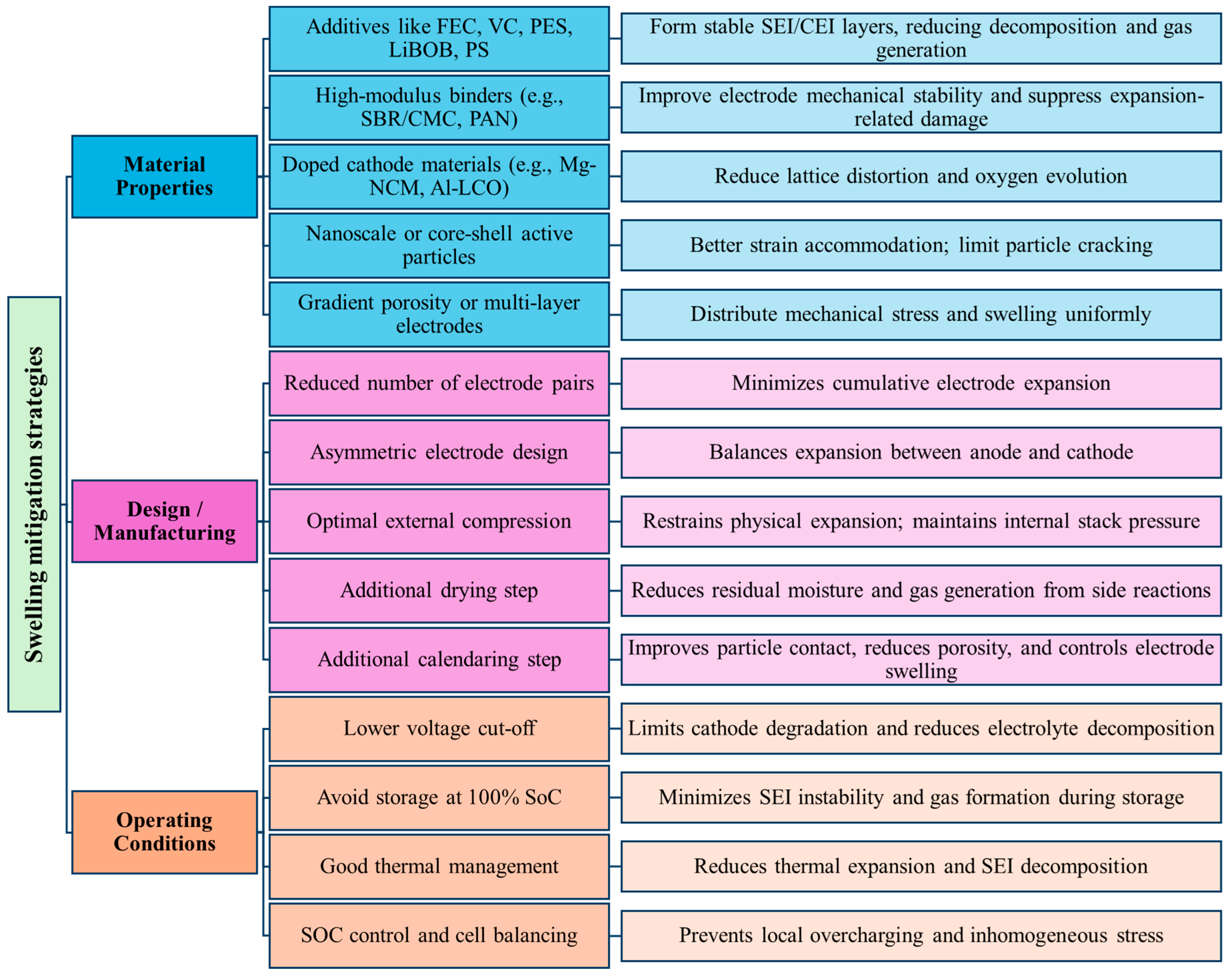
Swelling in LIBs is associated with the internal stresses that contribute to mechanical degradation, including fragmentation, disintegration, and fracturing of active materials, and can result in the loss of electrical contact between the current collector and the electrode. Such disconnections electrically isolate parts of the electrode and expose fresh surfaces to the electrolyte, triggering further side reactions. Fracturing of active materials also damages the SEI layer, which leads to repeated SEI formation and electrolyte consumption. Additionally, stress accumulation can reduce electrode porosity, limiting ionic transport [1,38,194,195]. Boyce et al. [196] suggest that many of the failure mechanisms, including fracture, cracking, and delamination, stem from diffusion-induced stress and volumetric strain. To address these issues, mitigation strategies must include modifying material properties, implementing effective cell design and manufacturing practices, and maintaining controlled operating conditions, as illustrated in Figure 10.
Chemical modifications have an impact on how cells irreversibly expand, particularly because gas generation is so closely linked to parasitic electrolyte redox reactions. Wu et al. [118] showed that cells with DMC alone swelled by ~325%, while most other single or binary electrolytes caused ~90–100% swelling under high-temperature conditions. In contrast, the PC + DMC (1:1) mixture reduced swelling to ~50% compared to standard electrolytes, due to the formation of a more protective film on the electrode surface. This demonstrates that solvent selection and synergy directly impact gas generation and swelling suppression.
Müllner et al. [197] have shown that CMC/SBR binders can stabilize fractured silicon or graphite particles and preserve the SEI, thereby reducing swelling compared to using a more elastic binder like PVDF. Doping Ni-rich NCM cathodes with small amounts of Mg or other cations, or doping LCO with aluminum (Al), strengthens the metal–oxygen bonds and reduces lattice distortion during lithium extraction [198]. Al doping is most effective in suppressing gas evolution from high-Ni layered cathodes by preventing oxygen release.
Lee et al. [199] controlled the swelling in silicon-based electrodes in LIBs through amorphous carbon-coated silicon/graphite granules (C@SGG) as an anode material. The authors measured the thickness change in the lithium-ion cells using an in situ electrode thickness measurement system to monitor the swelling behavior. The study addressed the swelling issue of silicon-based electrodes in LIBs by introducing amorphous carbon-coated silicon/graphite granules (C@SGG) as an anode material. The C@SGG electrode exhibits stable cycling performance with high reversible capacity (1150 mAh/g) and improved initial coulombic efficiency (85%). A pouch full cell with C@SGG as the anode and LiCoO2 as the cathode demonstrated long-term cyclability, retaining 71% capacity over 500 cycles at a 1C rate. Initial volume expansion of 12.7% was observed when first charged at 0.1C, and the volume expansion of 14.5% when charged at 1C. The swelling behavior of the C@SGG electrode showed an initial expansion of 16.0% at a charged state and a cycling expansion of 6.7% over 50 cycles. The study highlights the C@SGG as an anode material with improved electrochemical properties and regulated swelling behavior.
Zybert et al. [200] studied Na- and Nd-doped NMC622 cathodes for enhancing the structural stability of Ni-rich layered oxides during repeated lithiation/delithiation. Sodium ions, when introduced into the lithium layers, expanded the interplane spacing and acted as “pillars” that support the layered framework, thereby improving Li-ion diffusion and reducing stress accumulation from volume changes. Neodymium, on the other hand, substituted for transition metals in the oxide layers and formed strong Nd–O bonds, which suppressed lattice collapse, oxygen release, and microcracking. Zybert et al. [201] also studied Al- and Mg-doped NCM622 and observed that doping stabilized the layered structure and suppressed the H2–H3 phase transition, a known driver of anisotropic strain and microcracking. Improved cycling stability and reduced impedance growth were observed. However, these studies did not measure swelling, electrode thickness change, or stack pressure evolution. Consequently, the extent to which doping-induced structural stabilization translates to macroscopic swelling mitigation remains uncertain.
Su et al. [202] employed a multiscale operando approach combining synchrotron X-ray scattering and transmission X-ray microscopy to directly monitor electro-chemo-mechanical evolution in LiCoO2 cathodes under high C-rate (>1C) cycling. It was observed that particle cracking, agglomerate fragmentation, and nanoscale feature formation were the primary mechanisms behind capacity degradation and electrode swelling. However, by engineering a poly(3,4-ethylenedioxythiophene) (PEDOT) surface coating, the authors suppressed these degradation pathways, reducing surface deterioration, inhibiting LCO expansion, and extending cycling life. The study highlights the importance of surface modification in mitigating stress-induced swelling and demonstrates multiscale diagnostics in guiding cathode design.
Li et al. [203] demonstrated that the structure of SEI and electrode swelling in silicon-based anodes are influenced by the choice of material and electrode design. Porous Si/C–graphite composite electrodes, synthesized using electrochemical etching and carbon coating, were engineered to minimize volumetric expansion during cycling. The porous Si architecture with thin silicon walls surrounding large pores exhibited only about 30% volume expansion, less than that of nano-Si, which typically undergoes 300% expansion. This reduced swelling limited continuous SEI formation and electrolyte consumption, helping stabilize cycling performance. The SEI formed on the porous Si/C structure was stable, enabling high Coulombic efficiencies (~99.8% after initial cycles) and long-term retention (~82% over 450 cycles). An additional calendaring step improved particle packing to limit volume expansion in Si-anode-based LIBs. Electrode swelling was kept below 20% upon full lithiation and around 56% at end-of-life for calendared electrodes, compared to higher swelling in traditional Si systems (300%) [203]. Controlling Si content, particle porosity, and electrode calendaring are key strategies to achieve high capacity, stable cycling, and manageable swelling in practical silicon-based LIB anodes.
Jain et al. [204] conducted experiments that showed that using nano-sized active material particles or core–shell structured particles that accommodate strain from lithiation perform much better than large, homogeneous particles. When particle dimensions are on the order of ~100 nm or less, the lithium insertion-induced stress is more uniformly distributed and below the critical threshold for crack formation. Silicon particles below ~150 nm do not fracture upon full lithiation, whereas bulk silicon cracks due to internal strain [204]. However, in the case of LCO, a contrasting trend was observed by Su et al. [202] in which larger particles exhibited delayed cracking, whereas smaller particles fractured earlier during over-lithiation. This indicates that the relationship between particle size and mechanical resilience is material-specific and depends on crystallographic orientation, defect density, or surface energy. Material engineering, like a core–shell design with a shell buffering the active core, can confine expansion [204]. These strategies prevent particle pulverization and the continuous SEI reformation that generates gases.
Niu et al. [205] presented a high-energy (300 Wh/kg), 1.0 Ah lithium-metal pouch cell with minimized anode swelling and extended cycling performance, achieved through synergistic electrolyte design, cell configuration, and external pressure application. A major finding is that conventional carbonate electrolytes rapidly degrade the Li metal anode by forming thick, unstable SEI layers, producing electrically disconnected “dead” Li and leading to over 100% cell swelling and capacity fade within 12 cycles. Replacing the electrolyte with a LiFSI-TEP/BTFE system improves SEI stability, forming larger Li particles with lower surface area and reducing swelling to 74% over 50 cycles. The application of uniform 10 psi external pressure further enhances structural integrity, suppressing Li particle isolation, and supporting the formation of a porous, percolated Li structure that enables sustained ionic and electronic transport. This combined strategy limits swelling to 48% in the first 50 cycles and only 19% in the subsequent 150 cycles, allowing the cell to reach 200 cycles with 86% capacity retention. The study highlights that swelling arises during early SEI buildup and Li pulverization, and that controlling early-stage expansion is critical for safer Li metal batteries.
Park et al. [206] proposed an electrode microstructural engineering approach using a two-step calendaring process, where the first step allowed for the rearrangement of graphite particles, resulting in a uniform pore size and distribution throughout the electrode. This improved the swelling behavior and electrochemical properties of the electrode.
Zhang et al. [207] employed a design of an asymmetric electrode configuration to suppress the thickness increase in pouch cells. The sample with a thickness ratio of 1.05 exhibited the highest consistency in capacity retention ratio and the least swelling during cycle testing.
Spielbauer et al. [208] demonstrated that the initial gap between the jelly roll and the cylindrical casing strongly influences the mechanical stability and performance of the cell. If this gap is too small, swelling from both reversible breathing during cycling and irreversible expansion over the cell’s life can cause the jelly roll to press tightly against the casing. This results in elevated stresses, localized deformation, electrode delamination, and potential mechanical failure. To mitigate these issues, they suggested the use of compressible or buffer materials inside the casing. These materials can absorb and distribute the expansion forces, maintaining structural integrity.
Restricting the upper charge voltage of the cell prevents the accelerated electrolyte oxidation and structural stress that occur at high voltages. Keeping cells at full charge for extended periods is known to accelerate SEI degradation and gas buildup, so a lower storage state-of-charge is preferred. Calendar-aging studies have found that cells stored at high SoC suffer faster capacity loss and resistance growth, whereas cells stored at mid-level SoC fare much better. In particular, significant gas generation and lithium consumption occur in cells stored at 100% SoC due to continuous electrolyte oxidation on the charged cathode and SEI reactions on the lithiated anode [209]. Storing cells at, say, 40 to 60% SoC minimizes these processes [210].
SEI and electrolyte break down faster at higher temperatures, generating gases including CO2 and CO. Effective thermal management systems are therefore essential to limit temperature rise, stabilize interfacial layers, and reduce gas evolution under both storage and cycling conditions. Common thermal management approaches include air cooling, liquid cooling, and phase change materials (PCMs) [211,212]. Mini-channel liquid cooling plates [190], additive-manufactured heat exchangers [213], and advanced PCMs with enhanced thermal conductivity [214] improve heat removal while minimizing weight and space requirements. In parallel, materials with negative CTE are being investigated to counteract volume increases in battery components. These materials contract upon heating and can be integrated into composite structures to balance thermal deformation [215]. For example, materials like zirconium tungstate (ZrW2O8) and quaternary tungstate-type NTE ceramic (ZrScMo2VO12) exhibit negative CTE over a wide temperature range and have been explored as additives in electrodes [215,216]. Using such materials can help reduce internal stress, maintain structural integrity, and extend battery life during thermal cycling [216].
In multi-cell battery packs, managing SoC uniformity helps avoid localized overcharge, which can lead to increased gas generation. Small capacity imbalances between cells in a series-connected pack may cause one cell to reach full charge prematurely, entering overcharge conditions while others remain below their voltage limits. Overcharging induces electrolyte oxidation at the cathode and lithium plating at the anode, both of which result in gas generation and swelling [217]. Battery management systems (BMS) play a key role in mitigating this risk through active and passive cell balancing techniques. Passive balancing dissipates excess charge from higher-capacity cells as heat, while active balancing redistributes energy between cells to equalize SoC [218]. These approaches help maintain all cells within safe operating limits, reducing the risk of gas-related failure modes.

7. Discussion and Conclusions

Swelling of LIBs results from the interplay of electrochemical and mechanical mechanisms. Reversible swelling, ranging from 1% to 6% is primarily driven by intercalation-induced lattice expansion and thermal expansion. Graphite anodes consistently show ~10–14% lattice expansion during full lithiation [38,39], yet electrode-level expansion is typically limited to ~3–4% due to binder and porosity accommodation [45]. In contrast, silicon-based anodes show widely varying expansion (100–300%) depending on SiOx content and electrode design [47,69,70], with discrepancies arising in quantifying how much SEI thickening versus mechanical fracture contributes.
Irreversible swelling stems from gas generation, SEI/CEI layer growth, and lithium plating, which can collectively exceed 45% expansion. The SEI layer on graphite anodes contributes approximately 3.5–4% irreversible expansion during early cycles [44,64]. For silicon anodes, SEI thickness can increase from 22 to 72 nm within just 10 cycles [68], while SiOx composites can develop SEI layers hundreds of nanometers thick [68,69]. CEI swelling has been less studied; neutron reflectometry indicates ~37% volumetric expansion of the cathode [81], but standardized, cross-chemistry quantification of CEI evolution is lacking.
Lithium plating has been consistently linked to irreversible swelling at low temperatures and high C-rates [5,97]. However, discrepancies arise in separating plating-induced swelling from overlapping intercalation strain and SEI growth.
Gas evolution is the major driver of irreversible swelling. Some studies report CO as primary (56% of gas content) [107], while others emphasize ethylene and hydrogen under similar conditions [108,115]. These inconsistencies stem from differences in electrode material, electrolyte composition, cycling protocols, and gas chromatography sensitivity.
High C-rates consistently increase irreversible swelling, with up to 45% expansion observed under 4C/1.5C cycling [150]. Similarly, temperature effects are consistently reported where high temperatures accelerate SEI growth and gas evolution [8,157], while low temperatures induce plating and mossy lithium deposits [159]. However, SoC-dependence is less uniformly characterized where neutron imaging reveals swelling plateaus between 30 and 70% SoC [166], but other reports show linear or nonlinear dependencies depending on chemistry [62,168]. These discrepancies underscore the chemistry- and protocol-specific nature of swelling.
Given the substantial irreversible swelling caused by gas evolution, SEI/CEI growth, and lithium plating, effective mitigation strategies are critical to improve battery longevity and safety. PEDOT surface coatings, LiFSI-based electrolytes under controlled stack pressure, and silicon–carbon composites have achieved 30–50% reductions in expansion over hundreds of cycles, though trade-offs in energy density and scalability remain.
Experimental studies reveal a strong quantitative link between battery swelling and performance degradation metrics such as capacity fade and internal resistance. Reversible thickness changes track state of charge linearly, enabling real-time SoC estimation. Irreversible swelling increases with degradation and can indicate capacity loss, lithium inventory loss, and electrode delamination. Irreversible swelling beyond 20% correlates with a 150% rise in internal resistance and over 30% capacity fade [172]. Excessive swelling can therefore serve as an early indicator of battery stress and potential safety risks, including venting or thermal runaway.
Swelling is a potential diagnostic and prognostic signal. External strain gauges and force sensors bonded to cell casings can detect mechanical deformations that correlate not only with SoC and SoH but also with early indicators of thermal runaway. Embedded fiber Bragg gratings achieve ~1 µε resolution, enabling capacity fade predictions within 2% error over more than 300 cycles. Ultrasonic pulse echo detects gas bubble formation once swelling exceeds 2%, well before measurable capacity loss, and acoustic emission sensors capture plating-induced fracture events corresponding to under 1% irreversible expansion. Together, these methods enable a new class of health monitoring systems that could improve battery safety.
While swelling correlates with capacity fade, integration into battery management systems is still limited by sensor costs, calibration drift, and insufficient predictive capability for real-world operating conditions. Most mechanistic insights have been obtained from small-format cells and understanding how swelling behavior scales to large-format commercial cells, considering non-uniform expansion, mechanical constraints from cell stacking, and interactions within battery packs, remain underdeveloped. Current swelling models address subsets of mechanisms but fail to integrate preload-induced swelling, reversible contributions (intercalation and thermal), and irreversible aging-related expansion. While swelling is recognized as a precursor to venting and thermal runaway, the thresholds for “safe versus unsafe” swelling need to be defined. Standardized protocols for quantifying swelling under abuse conditions (e.g., overcharge, nail penetration, or external) would advance safety assessment.
Future research should focus on integrating swelling-based sensing techniques with electrochemical diagnostics and machine learning approaches to develop predictive frameworks capable of early failure detection and root-cause identification. This includes correlating in situ thickness or strain measurements with electrochemical tools such as EIS to link internal degradation processes with external mechanical responses, thereby refining swelling models. Complementary development of miniaturized sensors with high accuracy and stable long-term calibration is essential for integration into BMS and for enabling predictive, safety-focused battery management.

Author Contributions

Conceptualization, S.M., H.R. and M.P.; methodology, S.M. and H.R.; formal analysis, S.M. and H.R.; writing—original draft preparation, S.M. and H.R.; writing—review and editing, M.O., N.A. and M.P.; visualization, S.M.; supervision, M.P. All authors have read and agreed to the published version of the manuscript.

Funding

This work has been supported by the Electrochemical Safety Research Institute of UL Research Institutes through the Discoveries in Safety Grant Program.

Data Availability Statement

No new data were created or analyzed in this study. Data sharing is not applicable to this article.

Acknowledgments

The authors thank the Center for Advanced Life Cycle Engineering (CALCE) and its over 150 funding companies.

Conflicts of Interest

The authors declare no conflicts of interest.

Abbreviations

The following abbreviations are used in this manuscript:
LIBLithium-ion battery
SEISolid electrolyte interphase
CEICathode electrolyte interphase
LMOLithium manganese oxide
LFPLithium iron phosphate
LCOLithium cobalt oxide
NMCLithium nickel manganese cobalt oxide
NCALithium nickel cobalt aluminum oxide
CTECoefficient of thermal expansion
SoCState of charge
SoHState of health
PEPolyethylene
PPPolypropylene
XRDX-ray diffraction
LTOLithium titanate
FBGFiber Bragg grating
LiBOBLithium bis-(oxalate)borate
EISElectrochemical impedance spectroscopy
LEDCLithium ethylene dicarbonate
P2DPseudo-two-dimensional
C@SGGCoated silicon/graphite granules
PEDOTPoly(3,4-ethylenedioxythiophene)
PCMsPhase change materials
BMSBattery management system

References

  1. Vetter, J.; Novák, P.; Wagner, M.R.; Veit, C.; Möller, K.-C.; Besenhard, J.O.; Winter, M.; Wohlfahrt-Mehrens, M.; Vogler, C.; Hammouche, A. Ageing Mechanisms in Lithium-Ion Batteries. J. Power Sources 2005, 147, 269–281. [Google Scholar] [CrossRef]
  2. Lee, H.; Lim, H.-S.; Ren, X.; Yu, L.; Engelhard, M.H.; Han, K.S.; Lee, J.; Kim, H.-T.; Xiao, J.; Liu, J.; et al. Detrimental Effects of Chemical Crossover from the Lithium Anode to Cathode in Rechargeable Lithium Metal Batteries. ACS Energy Lett. 2018, 3, 2921–2930. [Google Scholar] [CrossRef]
  3. Guo, J.; Li, P.; Piccolo, F.; Jie, Y.; Jia, H.; Cao, R.; Jiao, S.; Adelhelm, P.; Xu, Y. Degradation and Failure Mechanisms of Lithium/LiNixCoyMn1−xyO2 Batteries. ACS Energy Lett. 2025, 10, 2318–2340. [Google Scholar] [CrossRef]
  4. Galushkin, N.E.; Yazvinskaya, N.N.; Galushkin, D.N. Mechanism of Gases Generation during Lithium-Ion Batteries Cycling. J. Electrochem. Soc. 2019, 166, A897–A908. [Google Scholar] [CrossRef]
  5. Bitzer, B.; Gruhle, A. A New Method for Detecting Lithium Plating by Measuring the Cell Thickness. J. Power Sources 2014, 262, 297–302. [Google Scholar] [CrossRef]
  6. Grimsmann, F.; Brauchle, F.; Gerbert, T.; Gruhle, A.; Parisi, J.; Knipper, M. Impact of Different Aging Mechanisms on the Thickness Change and the Quick-Charge Capability of Lithium-Ion Cells. J. Energy Storage 2017, 14, 158–162. [Google Scholar] [CrossRef]
  7. Li, X.; Zeng, T.; Qin, H.; Huo, R.; Liu, Y.; Wei, D.; Ding, X. Investigation of Inhomogeneous Degradation in Large-Format Lithium-Ion Batteries. J. Energy Storage 2021, 42, 103113. [Google Scholar] [CrossRef]
  8. Mohtat, P.; Lee, S.; Siegel, J.B.; Stefanopoulou, A.G. Reversible and Irreversible Expansion of Lithium-Ion Batteries Under a Wide Range of Stress Factors. J. Electrochem. Soc. 2021, 168, 100520. [Google Scholar] [CrossRef]
  9. Li, Y.; Wei, C.; Sheng, Y.; Jiao, F.; Wu, K. Swelling Force in Lithium-Ion Power Batteries. Ind. Eng. Chem. Res. 2020, 59, 12313–12318. [Google Scholar] [CrossRef]
  10. Heugel, P.; Märkle, W.; Deich, T.; Von Kessel, O.; Tübke, J. Thickness Change and Jelly Roll Deformation and Its Impact on the Aging and Lifetime of Commercial 18650 Cylindrical Li-Ion Cells with Silicon Containing Anodes and Nickel-Rich Cathodes. J. Energy Storage 2022, 53, 105101. [Google Scholar] [CrossRef]
  11. Cannarella, J.; Arnold, C.B. Stress Evolution and Capacity Fade in Constrained Lithium-Ion Pouch Cells. J. Power Sources 2014, 245, 745–751. [Google Scholar] [CrossRef]
  12. Oh, K.-Y.; Epureanu, B.I. Characterization and Modeling of the Thermal Mechanics of Lithium-Ion Battery Cells. Appl. Energy 2016, 178, 633–646. [Google Scholar] [CrossRef]
  13. Ellis, L.D.; Allen, J.P.; Thompson, L.M.; Harlow, J.E.; Stone, W.J.; Hill, I.G.; Dahn, J.R. Quantifying, Understanding and Evaluating the Effects of Gas Consumption in Lithium-Ion Cells. J. Electrochem. Soc. 2017, 164, A3518–A3528. [Google Scholar] [CrossRef]
  14. Aalund, R.; Endreddy, B.; Pecht, M. How Gas Generates in Pouch Cells and Affects Consumer Products. Front. Chem. Eng. 2022, 4, 828375. [Google Scholar] [CrossRef]
  15. Apple Now Offering Free Repairs of 42 mm Apple Watch Series 2 Models with Swollen Batteries. Available online: https://www.macrumors.com/2018/04/14/apple-watch-s2-swollen-battery-service-policy/ (accessed on 6 April 2025).
  16. fergie434. Macbook Battery Swelling Up. r/techsupportgore. 2013. Available online: https://www.reddit.com/r/techsupportgore/comments/1on9h2/macbook_battery_swelling_up/ (accessed on 6 April 2025).
  17. Ivan Apple Looking into iPhone 8 and 8 Plus Swelling Batteries Reports. Available online: https://www.gsmarena.com/does_the_iphone_8_and_8_plus_have_a_swelling_battery-news-27594.php (accessed on 6 April 2025).
  18. Krause, T.; Nusko, D.; Pitta Bauermann, L.; Vetter, M.; Schäfer, M.; Holly, C. Methods for Quantifying Expansion in Lithium-Ion Battery Cells Resulting from Cycling: A Review. Energies 2024, 17, 1566. [Google Scholar] [CrossRef]
  19. Maddipatla, S.; Kong, L.; Pecht, M. Safety Analysis of Lithium-Ion Cylindrical Batteries Using Design and Process Failure Mode and Effect Analysis. Batteries 2024, 10, 76. [Google Scholar] [CrossRef]
  20. Li, J.; Fleetwood, J.; Hawley, W.B.; Kays, W. From Materials to Cell: State-of-the-Art and Prospective Technologies for Lithium-Ion Battery Electrode Processing. Chem. Rev. 2022, 122, 903–956. [Google Scholar] [CrossRef]
  21. Wang, J.; Hao, F. Experimental Investigations on the Chemo-Mechanical Coupling in Solid-State Batteries and Electrode Materials. Energies 2023, 16, 1180. [Google Scholar] [CrossRef]
  22. Rieger, B.; Schlueter, S.; Erhard, S.V.; Schmalz, J.; Reinhart, G.; Jossen, A. Multi-Scale Investigation of Thickness Changes in a Commercial Pouch Type Lithium-Ion Battery. J. Energy Storage 2016, 6, 213–221. [Google Scholar] [CrossRef]
  23. Oh, K.-Y.; Siegel, J.B.; Secondo, L.; Kim, S.U.; Samad, N.A.; Qin, J.; Anderson, D.; Garikipati, K.; Knobloch, A.; Epureanu, B.I.; et al. Rate Dependence of Swelling in Lithium-Ion Cells. J. Power Sources 2014, 267, 197–202. [Google Scholar] [CrossRef]
  24. Shen, K.; Cao, X.; Huang, Z.-H.; Shen, W.; Kang, F. Microstructure and Thermal Expansion Behavior of Natural Microcrystalline Graphite. Carbon 2021, 177, 90–96. [Google Scholar] [CrossRef]
  25. Shi, D.; Xiao, X.; Huang, X.; Kia, H. Modeling Stresses in the Separator of a Pouch Lithium-Ion Cell. J. Power Sources 2011, 196, 8129–8139. [Google Scholar] [CrossRef]
  26. Valentin, O.; Thivel, P.-X.; Kareemulla, T.; Cadiou, F.; Bultel, Y. Modeling of Thermo-Mechanical Stresses in Li-Ion Battery. J. Energy Storage 2017, 13, 184–192. [Google Scholar] [CrossRef]
  27. Qu, M.; Woodford, W.H.; Maloney, J.M.; Carter, W.C.; Chiang, Y.; Van Vliet, K.J. Nanomechanical Quantification of Elastic, Plastic, and Fracture Properties of LiCoO2. Adv. Energy Mater. 2012, 2, 940–944. [Google Scholar] [CrossRef]
  28. Cheng, E.J.; Hong, K.; Taylor, N.J.; Choe, H.; Wolfenstine, J.; Sakamoto, J. Mechanical and Physical Properties of LiNi0.33Mn0.33Co0.33O2 (NMC). J. Eur. Ceram. Soc. 2017, 37, 3213–3217. [Google Scholar] [CrossRef]
  29. Shackelford, J.F.; Alexander, W. (Eds.) CRC Materials Science and Engineering Handbook; CRC Press: Boca Raton, FL, USA, 2000; ISBN 978-0-429-11786-2. [Google Scholar]
  30. Yan, S.; Deng, J.; Bae, C.; Xiao, X. Thermal Expansion/Shrinkage Measurement of Battery Separators Using a Dynamic Mechanical Analyzer. Polym. Test. 2018, 71, 65–71. [Google Scholar] [CrossRef]
  31. Wu, W.; Xiao, X.; Huang, X.; Yan, S. A Multiphysics Model for the in Situ Stress Analysis of the Separator in a Lithium-Ion Battery Cell. Comput. Mater. Sci. 2014, 83, 127–136. [Google Scholar] [CrossRef]
  32. Abdullah, M.A.; Albarody, T.M.B.; Hussein, A.R. Graphite Thermal Expansion Coefficient Measured by in-Situ x-Ray Diffraction. Nanotechnology 2020, 31, 285709. [Google Scholar] [CrossRef]
  33. Ma, S.; Jiang, M.; Tao, P.; Song, C.; Wu, J.; Wang, J.; Deng, T.; Shang, W. Temperature Effect and Thermal Impact in Lithium-Ion Batteries: A Review. Prog. Nat. Sci. Mater. Int. 2018, 28, 653–666. [Google Scholar] [CrossRef]
  34. Oh, K.-Y.; Epureanu, B.I. A Novel Thermal Swelling Model for a Rechargeable Lithium-Ion Battery Cell. J. Power Sources 2016, 303, 86–96. [Google Scholar] [CrossRef]
  35. Bezsonov, I.I.; Waller, G.H.; Ko, J.; Nadimpalli, S.P.V. In Operando Measurement of Surface Strain of 18650 Li-Ion Cells during Cycling. J. Power Sources 2024, 592, 233915. [Google Scholar] [CrossRef]
  36. Liu, C.; Neale, Z.G.; Cao, G. Understanding Electrochemical Potentials of Cathode Materials in Rechargeable Batteries. Mater. Today 2016, 19, 109–123. [Google Scholar] [CrossRef]
  37. Yoon, W.-S.; Chung, K.Y.; McBreen, J.; Yang, X.-Q. A Comparative Study on Structural Changes of LiCo1/3Ni1/3Mn1/3O2 and LiNi0.8Co0.15Al0.05O2 during First Charge Using in Situ XRD. Electrochem. Commun. 2006, 8, 1257–1262. [Google Scholar] [CrossRef]
  38. Mukhopadhyay, A.; Sheldon, B.W. Deformation and Stress in Electrode Materials for Li-Ion Batteries. Prog. Mater. Sci. 2014, 63, 58–116. [Google Scholar] [CrossRef]
  39. Qi, Y.; Guo, H.; Hector, L.G.; Timmons, A. Threefold Increase in the Young’s Modulus of Graphite Negative Electrode during Lithium Intercalation. J. Electrochem. Soc. 2010, 157, A558. [Google Scholar] [CrossRef]
  40. Winter, M.; Wrodnigg, G.H.; Besenhard, J.O.; Biberacher, W.; Novák, P. Dilatometric Investigations of Graphite Electrodes in Nonaqueous Lithium Battery Electrolytes. J. Electrochem. Soc. 2000, 147, 2427. [Google Scholar] [CrossRef]
  41. Massoudi, A.; Nangir, M.; Moghadami, M. Characterization of Battery Materials by Mechanical Measurements. In Nanostructured Materials Engineering and Characterization for Battery Applications; Elsevier: Amsterdam, The Netherlands, 2024; pp. 373–437. ISBN 978-0-323-91304-1. [Google Scholar]
  42. Asenbauer, J.; Eisenmann, T.; Kuenzel, M.; Kazzazi, A.; Chen, Z.; Bresser, D. The Success Story of Graphite as a Lithium-Ion Anode Material–Fundamentals, Remaining Challenges, and Recent Developments Including Silicon (Oxide) Composites. Sustain. Energy Fuels 2020, 4, 5387–5416. [Google Scholar] [CrossRef]
  43. Zhang, H.; Yang, Y.; Ren, D.; Wang, L.; He, X. Graphite as Anode Materials: Fundamental Mechanism, Recent Progress and Advances. Energy Storage Mater. 2021, 36, 147–170. [Google Scholar] [CrossRef]
  44. Hahn, M.; Buqa, H.; Ruch, P.W.; Goers, D.; Spahr, M.E.; Ufheil, J.; Novák, P.; Kötz, R. A Dilatometric Study of Lithium Intercalation into Powder-Type Graphite Electrodes. Electrochem. Solid-State Lett. 2008, 11, A151. [Google Scholar] [CrossRef]
  45. Liu, X.H.; Zheng, H.; Zhong, L.; Huang, S.; Karki, K.; Zhang, L.Q.; Liu, Y.; Kushima, A.; Liang, W.T.; Wang, J.W.; et al. Anisotropic Swelling and Fracture of Silicon Nanowires during Lithiation. Nano Lett. 2011, 11, 3312–3318. [Google Scholar] [CrossRef] [PubMed]
  46. Qian, G.; Li, Y.; Chen, H.; Xie, L.; Liu, T.; Yang, N.; Song, Y.; Lin, C.; Cheng, J.; Nakashima, N.; et al. Revealing the Aging Process of Solid Electrolyte Interphase on SiOx Anode. Nat. Commun. 2023, 14, 6048. [Google Scholar] [CrossRef]
  47. Zhao, P.-Y.; Zhang, S.; Choy, K.-L.; Song, Y.; Zhang, S.; Guo, D.; Yang, C. Silicon Negative Electrodes for Lithium-Ion Batteries: Challenges, Advances, and Future Prospects. Mater. Horiz. 2025, 12, 6440–6484. [Google Scholar] [CrossRef]
  48. Cheng, H.; Shapter, J.G.; Li, Y.; Gao, G. Recent Progress of Advanced Anode Materials of Lithium-Ion Batteries. J. Energy Chem. 2021, 57, 451–468. [Google Scholar] [CrossRef]
  49. Sandhya, C.P.; John, B.; Gouri, C. Lithium Titanate as Anode Material for Lithium-Ion Cells: A Review. Ionics 2014, 20, 601–620. [Google Scholar] [CrossRef]
  50. Julien, C.; Mauger, A.; Zaghib, K.; Groult, H. Comparative Issues of Cathode Materials for Li-Ion Batteries. Inorganics 2014, 2, 132–154. [Google Scholar] [CrossRef]
  51. Zhao, S.; Yan, K.; Zhang, J.; Sun, B.; Wang, G. Reaction Mechanisms of Layered Lithium-Rich Cathode Materials for High-Energy Lithium-Ion Batteries. Angew. Chem. Int. Ed. 2021, 60, 2208–2220. [Google Scholar] [CrossRef]
  52. He, P.; Yu, H.; Li, D.; Zhou, H. Layered Lithium Transition Metal Oxide Cathodes towards High Energy Lithium-Ion Batteries. J. Mater. Chem. 2012, 22, 3680. [Google Scholar] [CrossRef]
  53. Rieger, B.; Schlueter, S.; Erhard, S.V.; Jossen, A. Strain Propagation in Lithium-Ion Batteries from the Crystal Structure to the Electrode Level. J. Electrochem. Soc. 2016, 163, A1595–A1606. [Google Scholar] [CrossRef]
  54. Reimers, J.N.; Dahn, J.R. Electrochemical and In Situ X-Ray Diffraction Studies of Lithium Intercalation in LixCoO2. J. Electrochem. Soc. 1992, 139, 2091–2097. [Google Scholar] [CrossRef]
  55. Zhang, Y.; Zhang, W.; Zhou, J.; Li, X.; Zhou, W.; Xie, Y.; Mao, J.; Dai, K. Research Development on Spinel Lithium Manganese Oxides Cathode Materials for Lithium-Ion Batteries. J. Electrochem. Soc. 2023, 170, 090532. [Google Scholar] [CrossRef]
  56. Arabolla Rodríguez, R.; González Montiel, M.; Della Santina Mohallem, N.; Mosqueda Laffita, Y.; Andrey Montoro, L.; Avila Santos, M.; León Ramírez, H.; Pérez-Cappe, E.L. The Role of Defects on the Jahn-Teller Effect and Electrochemical Charge Storage in Nanometric LiMn2O4 Material. Solid State Ion. 2021, 369, 115707. [Google Scholar] [CrossRef]
  57. Stallard, J.C.; Wheatcroft, L.; Booth, S.G.; Boston, R.; Corr, S.A.; De Volder, M.F.L.; Inkson, B.J.; Fleck, N.A. Mechanical Properties of Cathode Materials for Lithium-Ion Batteries. Joule 2022, 6, 984–1007. [Google Scholar] [CrossRef]
  58. Wang, X.; Sone, Y.; Kuwajima, S. In Situ Investigation of the Volume Change in Li-Ion Cell with Charging and Discharging. J. Electrochem. Soc. 2004, 151, A273. [Google Scholar] [CrossRef]
  59. Sauerteig, D.; Hanselmann, N.; Arzberger, A.; Reinshagen, H.; Ivanov, S.; Bund, A. Electrochemical-Mechanical Coupled Modeling and Parameterization of Swelling and Ionic Transport in Lithium-Ion Batteries. J. Power Sources 2018, 378, 235–247. [Google Scholar] [CrossRef]
  60. Wünsch, M.; Kaufman, J.; Sauer, D.U. Investigation of the Influence of Different Bracing of Automotive Pouch Cells on Cyclic Liefetime and Impedance Spectra. J. Energy Storage 2019, 21, 149–155. [Google Scholar] [CrossRef]
  61. Zhao, X.; Yin, Y.; Hu, Y.; Choe, S.-Y. Electrochemical-Thermal Modeling of Lithium Plating/Stripping of Li(Ni0.6Mn0.2Co0.2)O2/Carbon Lithium-Ion Batteries at Subzero Ambient Temperatures. J. Power Sources 2019, 418, 61–73. [Google Scholar] [CrossRef]
  62. Lee, J.H.; Lee, H.M.; Ahn, S. Battery Dimensional Changes Occurring during Charge/Discharge Cycles—Thin Rectangular Lithium Ion and Polymer Cells. J. Power Sources 2003, 119–121, 833–837. [Google Scholar] [CrossRef]
  63. Siegel, J.B.; Stefanopoulou, A.G.; Hagans, P.; Ding, Y.; Gorsich, D. Expansion of Lithium Ion Pouch Cell Batteries: Observations from Neutron Imaging. J. Electrochem. Soc. 2013, 160, A1031–A1038. [Google Scholar] [CrossRef]
  64. Sauerteig, D.; Ivanov, S.; Reinshagen, H.; Bund, A. Reversible and Irreversible Dilation of Lithium-Ion Battery Electrodes Investigated by in-Situ Dilatometry. J. Power Sources 2017, 342, 939–946. [Google Scholar] [CrossRef]
  65. Zhao, Y.; Spingler, F.B.; Patel, Y.; Offer, G.J.; Jossen, A. Localized Swelling Inhomogeneity Detection in Lithium Ion Cells Using Multi-Dimensional Laser Scanning. J. Electrochem. Soc. 2019, 166, A27–A34. [Google Scholar] [CrossRef]
  66. Wang, A.; Kadam, S.; Li, H.; Shi, S.; Qi, Y. Review on Modeling of the Anode Solid Electrolyte Interphase (SEI) for Lithium-Ion Batteries. npj Comput. Mater. 2018, 4, 15. [Google Scholar] [CrossRef]
  67. Bernhard, R.; Metzger, M.; Gasteiger, H.A. Gas Evolution at Graphite Anodes Depending on Electrolyte Water Content and SEI Quality Studied by On-Line Electrochemical Mass Spectrometry. J. Electrochem. Soc. 2015, 162, A1984–A1989. [Google Scholar] [CrossRef]
  68. Peled, E.; Patolsky, F.; Golodnitsky, D.; Freedman, K.; Davidi, G.; Schneier, D. Tissue-like Silicon Nanowires-Based Three-Dimensional Anodes for High-Capacity Lithium Ion Batteries. Nano Lett. 2015, 15, 3907–3916. [Google Scholar] [CrossRef] [PubMed]
  69. Zhen, H.; Meng, F.; Gao, J.; Liu, Y.; Liu, X. Asymmetric Swelling Behaviors of High-Energy-Density Lithium-Ion Batteries with a SiOx/Graphite Composite Anode. Small 2023, 19, 2300500. [Google Scholar] [CrossRef]
  70. Dopilka, A.; Larson, J.M.; Kostecki, R. Operando Infrared Nanospectroscopy of the Silicon/Electrolyte Interface during Initial Stages of Solid-Electrolyte-Interphase Layer Formation. ACS Energy Lett. 2025, 10, 410–419. [Google Scholar] [CrossRef]
  71. Zhang, Z.; Li, Y.; Xu, R.; Zhou, W.; Li, Y.; Oyakhire, S.T.; Wu, Y.; Xu, J.; Wang, H.; Yu, Z.; et al. Capturing the Swelling of Solid-Electrolyte Interphase in Lithium Metal Batteries. Science 2022, 375, 66–70. [Google Scholar] [CrossRef]
  72. Kim, K.; Ma, H.; Park, S.; Choi, N.-S. Electrolyte-Additive-Driven Interfacial Engineering for High-Capacity Electrodes in Lithium-Ion Batteries: Promise and Challenges. ACS Energy Lett. 2020, 5, 1537–1553. [Google Scholar] [CrossRef]
  73. Jaumann, T.; Balach, J.; Langklotz, U.; Sauchuk, V.; Fritsch, M.; Michaelis, A.; Teltevskij, V.; Mikhailova, D.; Oswald, S.; Klose, M.; et al. Lifetime vs. Rate Capability: Understanding the Role of FEC and VC in High-Energy Li-Ion Batteries with Nano-Silicon Anodes. Energy Storage Mater. 2017, 6, 26–35. [Google Scholar] [CrossRef]
  74. Jung, R.; Metzger, M.; Haering, D.; Solchenbach, S.; Marino, C.; Tsiouvaras, N.; Stinner, C.; Gasteiger, H.A. Consumption of Fluoroethylene Carbonate (FEC) on Si-C Composite Electrodes for Li-Ion Batteries. J. Electrochem. Soc. 2016, 163, A1705–A1716. [Google Scholar] [CrossRef]
  75. Bhattacharya, S.; Alpas, A.T. Micromechanisms of Solid Electrolyte Interphase Formation on Electrochemically Cycled Graphite Electrodes in Lithium-Ion Cells. Carbon 2012, 50, 5359–5371. [Google Scholar] [CrossRef]
  76. Agubra, V.A.; Fergus, J.W. The Formation and Stability of the Solid Electrolyte Interface on the Graphite Anode. J. Power Sources 2014, 268, 153–162. [Google Scholar] [CrossRef]
  77. Wood, D.L.; Li, J.; Daniel, C. Prospects for Reducing the Processing Cost of Lithium Ion Batteries. J. Power Sources 2015, 275, 234–242. [Google Scholar] [CrossRef]
  78. Ota, M.; Izuo, S.; Nishikawa, K.; Fukunaka, Y.; Kusaka, E.; Ishii, R.; Selman, J.R. Measurement of Concentration Boundary Layer Thickness Development during Lithium Electrodeposition onto a Lithium Metal Cathode in Propylene Carbonate. J. Electroanal. Chem. 2003, 559, 175–183. [Google Scholar] [CrossRef]
  79. Jha, V.; Krishnamurthy, B. Modeling the SEI Layer Formation and Its Growth in Lithium-Ion Batteries (LiB) during Charge–Discharge Cycling. Ionics 2022, 28, 3661–3670. [Google Scholar] [CrossRef]
  80. Xu, J. Critical Review on Cathode–Electrolyte Interphase Toward High-Voltage Cathodes for Li-Ion Batteries. Nano-Micro Lett. 2022, 14, 166. [Google Scholar] [CrossRef]
  81. .Zhang, N.; Wang, B.; Jin, F.; Chen, Y.; Jiang, Y.; Bao, C.; Tian, J.; Wang, J.; Xu, R.; Li, Y.; et al. Modified Cathode-Electrolyte Interphase toward High-Performance Batteries. Cell Rep. Phys. Sci. 2022, 3, 101197. [Google Scholar] [CrossRef]
  82. Bonefacino, J.; Ghashghaie, S.; Zheng, T.; Lin, C.-P.; Zheng, W.; Blanquer, L.A.; Huang, J.; Gervillié, C.; Tam, H.-Y.; Tarascon, J.-M.; et al. High-Fidelity Strain and Temperature Measurements of Li-Ion Batteries Using Polymer Optical Fiber Sensors. J. Electrochem. Soc. 2022, 169, 100508. [Google Scholar] [CrossRef]
  83. Heidrich, B.; Pritzlaff, L.; Börner, M.; Winter, M.; Niehoff, P. Comparative X-Ray Photoelectron Spectroscopy Study of the SEI and CEI in Three Different Lithium Ion Cell Formats. J. Electrochem. Soc. 2022, 169, 030533. [Google Scholar] [CrossRef]
  84. Waldmann, T.; Hogg, B.-I.; Wohlfahrt-Mehrens, M. Li Plating as Unwanted Side Reaction in Commercial Li-Ion Cells—A Review. J. Power Sources 2018, 384, 107–124. [Google Scholar] [CrossRef]
  85. Legrand, N.; Knosp, B.; Desprez, P.; Lapicque, F.; Raël, S. Physical Characterization of the Charging Process of a Li-Ion Battery and Prediction of Li Plating by Electrochemical Modelling. J. Power Sources 2014, 245, 208–216. [Google Scholar] [CrossRef]
  86. Arora, P.; Doyle, M.; White, R.E. Mathematical Modeling of the Lithium Deposition Overcharge Reaction in Lithium-Ion Batteries Using Carbon-Based Negative Electrodes. J. Electrochem. Soc. 1999, 146, 3543–3553. [Google Scholar] [CrossRef]
  87. Yan, C.; Zhang, Q. Towards the Intercalation and Lithium Plating Mechanism for High Safety and Fast-Charging Lithium-Ion Batteries: A Review. Energy Lab 2022, 1, 220011. [Google Scholar] [CrossRef]
  88. Liu, S.; Xiong, L.; He, C. Long Cycle Life Lithium Ion Battery with Lithium Nickel Cobalt Manganese Oxide (NCM) Cathode. J. Power Sources 2014, 261, 285–291. [Google Scholar] [CrossRef]
  89. Ebner, M.; Wood, V. Tool for Tortuosity Estimation in Lithium Ion Battery Porous Electrodes. J. Electrochem. Soc. 2015, 162, A3064–A3070. [Google Scholar] [CrossRef]
  90. Kehrwald, D.; Shearing, P.R.; Brandon, N.P.; Sinha, P.K.; Harris, S.J. Local Tortuosity Inhomogeneities in a Lithium Battery Composite Electrode. J. Electrochem. Soc. 2011, 158, A1393. [Google Scholar] [CrossRef]
  91. Daubinger, P.; Schelter, M.; Petersohn, R.; Nagler, F.; Hartmann, S.; Herrmann, M.; Giffin, G.A. Impact of Bracing on Large Format Prismatic Lithium-Ion Battery Cells during Aging. Adv. Energy Mater. 2022, 12, 2102448. [Google Scholar] [CrossRef]
  92. Zhang, S.S. Uncovering the Root Leading to Accelerated Capacity Fade of Li-Ion Coin Cells in Fast Charging. Energy Technol. 2023, 11, 2200370. [Google Scholar] [CrossRef]
  93. Cao, C.; Steinrück, H.-G.; Paul, P.P.; Dunlop, A.R.; Trask, S.E.; Jansen, A.N.; Kasse, R.M.; Thampy, V.; Yusuf, M.; Weker, J.N.; et al. Conformal Pressure and Fast-Charging Li-Ion Batteries. J. Electrochem. Soc. 2022, 169, 040540. [Google Scholar] [CrossRef]
  94. Bauer, M.; Wachtler, M.; Stöwe, H.; Persson, J.V.; Danzer, M.A. Understanding the Dilation and Dilation Relaxation Behavior of Graphite-Based Lithium-Ion Cells. J. Power Sources 2016, 317, 93–102. [Google Scholar] [CrossRef]
  95. Rieger, B.; Schuster, S.F.; Erhard, S.V.; Osswald, P.J.; Rheinfeld, A.; Willmann, C.; Jossen, A. Multi-Directional Laser Scanning as Innovative Method to Detect Local Cell Damage during Fast Charging of Lithium-Ion Cells. J. Energy Storage 2016, 8, 1–5. [Google Scholar] [CrossRef]
  96. Grimsmann, F.; Gerbert, T.; Brauchle, F.; Gruhle, A.; Parisi, J.; Knipper, M. Determining the Maximum Charging Currents of Lithium-Ion Cells for Small Charge Quantities. J. Power Sources 2017, 365, 12–16. [Google Scholar] [CrossRef]
  97. Gao, X.-L.; Liu, X.-H.; Xie, W.-L.; Zhang, L.-S.; Yang, S.-C. Multiscale Observation of Li Plating for Lithium-Ion Batteries. Rare Met. 2021, 40, 3038–3048. [Google Scholar] [CrossRef]
  98. Tanim, T.R.; Dufek, E.J.; Dickerson, C.C.; Wood, S.M. Electrochemical Quantification of Lithium Plating: Challenges and Considerations. J. Electrochem. Soc. 2019, 166, A2689–A2696. [Google Scholar] [CrossRef]
  99. Tian, Y.; Lin, C.; Li, H.; Du, J.; Xiong, R. Detecting Undesired Lithium Plating on Anodes for Lithium-Ion Batteries—A Review on the in-Situ Methods. Appl. Energy 2021, 300, 117386. [Google Scholar] [CrossRef]
  100. Lin, X.; Khosravinia, K.; Hu, X.; Li, J.; Lu, W. Lithium Plating Mechanism, Detection, and Mitigation in Lithium-Ion Batteries. Prog. Energy Combust. Sci. 2021, 87, 100953. [Google Scholar] [CrossRef]
  101. Janakiraman, U.; Garrick, T.R.; Fortier, M.E. Review—Lithium Plating Detection Methods in Li-Ion Batteries. J. Electrochem. Soc. 2020, 167, 160552. [Google Scholar] [CrossRef]
  102. Bommier, C.; Chang, W.; Lu, Y.; Yeung, J.; Davies, G.; Mohr, R.; Williams, M.; Steingart, D. In Operando Acoustic Detection of Lithium Metal Plating in Commercial LiCoO2/Graphite Pouch Cells. Cell Rep. Phys. Sci. 2020, 1, 100035. [Google Scholar] [CrossRef]
  103. Maiser, E. Battery Packaging-Technology Review. AIP Conf. Proc. 2014, 1597, 204–218. [Google Scholar]
  104. Leißing, M.; Horsthemke, F.; Wiemers-Meyer, S.; Winter, M.; Niehoff, P.; Nowak, S. The Impact of the C-Rate on Gassing During Formation of NMC622 II Graphite Lithium-Ion Battery Cells. Batter. Supercaps 2021, 4, 1344–1350. [Google Scholar] [CrossRef]
  105. Wang, H.; Rus, E.; Sakuraba, T.; Kikuchi, J.; Kiya, Y.; Abruña, H.D. CO2 and O2 Evolution at High Voltage Cathode Materials of Li-Ion Batteries: A Differential Electrochemical Mass Spectrometry Study. Anal. Chem. 2014, 86, 6197–6201. [Google Scholar] [CrossRef] [PubMed]
  106. Lee, S.-H.; Ko, I.-H. Failure Analysis of Swelling in Prismatic Lithium-Ion Batteries During Their Cycle Life After Long-Term Storage. J. Fail. Anal. Prev. 2018, 18, 554–561. [Google Scholar] [CrossRef]
  107. Xu, P.; Li, J.; Lei, N.; Zhou, F.; Sun, C. An Experimental Study on the Mechanical Characteristics of Li-ion Battery during Overcharge-induced Thermal Runaway. Int. J. Energy Res. 2021, 45, 19985–20000. [Google Scholar] [CrossRef]
  108. Rowden, B.; Garcia-Araez, N. A Review of Gas Evolution in Lithium Ion Batteries. Energy Rep. 2020, 6, 10–18. [Google Scholar] [CrossRef]
  109. Zheng, T.; Muneeswara, M.; Bao, H.; Huang, J.; Zhang, L.; Hall, D.S.; Boles, S.T.; Jin, W. Gas Evolution in Li-Ion Rechargeable Batteries: A Review on Operando Sensing Technologies, Gassing Mechanisms, and Emerging Trends. ChemElectroChem 2024, 11, e202400065. [Google Scholar] [CrossRef]
  110. Metzger, M.; Strehle, B.; Solchenbach, S.; Gasteiger, H.A. Origin of H2 Evolution in LIBs: H2O Reduction vs. Electrolyte Oxidation. J. Electrochem. Soc. 2016, 163, A798–A809. [Google Scholar] [CrossRef]
  111. An, S.J.; Li, J.; Daniel, C.; Mohanty, D.; Nagpure, S.; Wood, D.L. The State of Understanding of the Lithium-Ion-Battery Graphite Solid Electrolyte Interphase (SEI) and Its Relationship to Formation Cycling. Carbon 2016, 105, 52–76. [Google Scholar] [CrossRef]
  112. Xiong, D.J.; Petibon, R.; Madec, L.; Hall, D.S.; Dahn, J.R. Some Effects of Intentionally Added Water on LiCoO2/Graphite Pouch Cells. J. Electrochem. Soc. 2016, 163, A1678–A1685. [Google Scholar] [CrossRef]
  113. Mogi, R.; Inaba, M.; Iriyama, Y.; Abe, T.; Ogumi, Z. Study on the Decomposition Mechanism of Alkyl Carbonate on Lithium Metal by Pyrolysis-Gas Chromatography-Mass Spectroscopy. J. Power Sources 2003, 119–121, 597–603. [Google Scholar] [CrossRef]
  114. Yang, Y.-L.; Ramaswamy, S.G.; Jakoby, W.B. Enzymatic Hydrolysis of Organic Cyclic Carbonates. J. Biol. Chem. 1998, 273, 7814–7817. [Google Scholar] [CrossRef]
  115. Rodrigues, M.-T.F.; Kalaga, K.; Trask, S.E.; Shkrob, I.A.; Abraham, D.P. Anode-Dependent Impedance Rise in Layered-Oxide Cathodes of Lithium-Ion Cells. J. Electrochem. Soc. 2018, 165, A1697–A1705. [Google Scholar] [CrossRef]
  116. Ohzuku, T.; Ueda, A.; Yamamoto, N. Zero-Strain Insertion Material of Li[Li1/3Ti5/3]O4 for Rechargeable Lithium Cells. J. Electrochem. Soc. 1995, 142, 1431–1435. [Google Scholar] [CrossRef]
  117. Han, C.; He, Y.-B.; Liu, M.; Li, B.; Yang, Q.-H.; Wong, C.-P.; Kang, F. A Review of Gassing Behavior in Li4Ti5O12-Based Lithium Ion Batteries. J. Mater. Chem. A 2017, 5, 6368–6381. [Google Scholar] [CrossRef]
  118. Wu, K.; Yang, J.; Liu, Y.; Zhang, Y.; Wang, C.; Xu, J.; Ning, F.; Wang, D. Investigation on Gas Generation of Li4Ti5O12/LiNi1/3Co1/3Mn1/3O2 Cells at Elevated Temperature. J. Power Sources 2013, 237, 285–290. [Google Scholar] [CrossRef]
  119. Flügel, M.; Waldmann, T.; Kasper, M.; Wohlfahrt-Mehrens, M. Detection of Copper Deposition on Anodes of Over-Discharged Lithium Ion Cells by GD-OES Depth Profiling. ChemPhysChem 2020, 21, 2047–2050. [Google Scholar] [CrossRef]
  120. Guo, L.; Thornton, D.B.; Koronfel, M.A.; Stephens, I.E.L.; Ryan, M.P. Degradation in Lithium Ion Battery Current Collectors. J. Phys. Energy 2021, 3, 032015. [Google Scholar] [CrossRef]
  121. Hatsukade, T.; Schiele, A.; Hartmann, P.; Brezesinski, T.; Janek, J. Origin of Carbon Dioxide Evolved during Cycling of Nickel-Rich Layered NCM Cathodes. ACS Appl. Mater. Interfaces 2018, 10, 38892–38899. [Google Scholar] [CrossRef]
  122. Renfrew, S.E.; McCloskey, B.D. Residual Lithium Carbonate Predominantly Accounts for First Cycle CO2 and CO Outgassing of Li-Stoichiometric and Li-Rich Layered Transition-Metal Oxides. J. Am. Chem. Soc. 2017, 139, 17853–17860. [Google Scholar] [CrossRef]
  123. Mahne, N.; Renfrew, S.E.; McCloskey, B.D.; Freunberger, S.A. Electrochemical Oxidation of Lithium Carbonate Generates Singlet Oxygen. Angew. Chem. Int. Ed. 2018, 57, 5529–5533. [Google Scholar] [CrossRef] [PubMed]
  124. Jung, R.; Metzger, M.; Maglia, F.; Stinner, C.; Gasteiger, H.A. Oxygen Release and Its Effect on the Cycling Stability of LiNixMnyCozO2 (NMC) Cathode Materials for Li-Ion Batteries. J. Electrochem. Soc. 2017, 164, A1361–A1377. [Google Scholar] [CrossRef]
  125. Wandt, J.; Freiberg, A.T.S.; Ogrodnik, A.; Gasteiger, H.A. Singlet Oxygen Evolution from Layered Transition Metal Oxide Cathode Materials and Its Implications for Lithium-Ion Batteries. Mater. Today 2018, 21, 825–833. [Google Scholar] [CrossRef]
  126. Streich, D.; Erk, C.; Guéguen, A.; Müller, P.; Chesneau, F.-F.; Berg, E.J. Operando Monitoring of Early Ni-Mediated Surface Reconstruction in Layered Lithiated Ni–Co–Mn Oxides. J. Phys. Chem. C 2017, 121, 13481–13486. [Google Scholar] [CrossRef]
  127. Rinkel, B.L.D.; Vivek, J.P.; Garcia-Araez, N.; Grey, C.P. Two Electrolyte Decomposition Pathways at Nickel-Rich Cathode Surfaces in Lithium-Ion Batteries. Energy Environ. Sci. 2022, 15, 3416–3438. [Google Scholar] [CrossRef]
  128. Onuki, M.; Kinoshita, S.; Sakata, Y.; Yanagidate, M.; Otake, Y.; Ue, M.; Deguchi, M. Identification of the Source of Evolved Gas in Li-Ion Batteries Using [Sup 13]C-Labeled Solvents. J. Electrochem. Soc. 2008, 155, A794. [Google Scholar] [CrossRef]
  129. Metzger, M.; Marino, C.; Sicklinger, J.; Haering, D.; Gasteiger, H.A. Anodic Oxidation of Conductive Carbon and Ethylene Carbonate in High-Voltage Li-Ion Batteries Quantified by On-Line Electrochemical Mass Spectrometry. J. Electrochem. Soc. 2015, 162, A1123–A1134. [Google Scholar] [CrossRef]
  130. Guéguen, A.; Streich, D.; He, M.; Mendez, M.; Chesneau, F.F.; Novák, P.; Berg, E.J. Decomposition of LiPF6 in High Energy Lithium-Ion Batteries Studied with Online Electrochemical Mass Spectrometry. J. Electrochem. Soc. 2016, 163, A1095–A1100. [Google Scholar] [CrossRef]
  131. Renfrew, S.E.; Kaufman, L.A.; McCloskey, B.D. Altering Surface Contaminants and Defects Influences the First-Cycle Outgassing and Irreversible Transformations of LiNi0.6Mn0.2Co0.2O2. ACS Appl. Mater. Interfaces 2019, 11, 34913–34921. [Google Scholar] [CrossRef]
  132. Kaufman, L.A.; Huang, T.-Y.; Lee, D.; McCloskey, B.D. Particle Surface Cracking Is Correlated with Gas Evolution in High-Ni Li-Ion Cathode Materials. ACS Appl. Mater. Interfaces 2022, 14, 39959–39964. [Google Scholar] [CrossRef]
  133. Michalak, B.; Sommer, H.; Mannes, D.; Kaestner, A.; Brezesinski, T.; Janek, J. Gas Evolution in Operating Lithium-Ion Batteries Studied In Situ by Neutron Imaging. Sci. Rep. 2015, 5, 15627. [Google Scholar] [CrossRef] [PubMed]
  134. Shi, X.; Zhang, H.; Zhang, Y.; Liu, J.; Zhang, J.; Li, L. Corrosion and Protection of Aluminum Current Collector in Lithium-Ion Batteries. Innov. Mater. 2023, 1, 100030. [Google Scholar] [CrossRef]
  135. Kim, Y. Investigation of the Gas Evolution in Lithium Ion Batteries: Effect of Free Lithium Compounds in Cathode Materials. J. Solid State Electrochem. 2013, 17, 1961–1965. [Google Scholar] [CrossRef]
  136. Jung, R.; Metzger, M.; Maglia, F.; Stinner, C.; Gasteiger, H.A. Chemical versus Electrochemical Electrolyte Oxidation on NMC111, NMC622, NMC811, LNMO, and Conductive Carbon. J. Phys. Chem. Lett. 2017, 8, 4820–4825. [Google Scholar] [CrossRef] [PubMed]
  137. He, Q.; Cairns, E.J. Review—Recent Progress in Electrocatalysts for Oxygen Reduction Suitable for Alkaline Anion Exchange Membrane Fuel Cells. J. Electrochem. Soc. 2015, 162, F1504–F1539. [Google Scholar] [CrossRef]
  138. Nie, M.; Chalasani, D.; Abraham, D.P.; Chen, Y.; Bose, A.; Lucht, B.L. Lithium Ion Battery Graphite Solid Electrolyte Interphase Revealed by Microscopy and Spectroscopy. J. Phys. Chem. C 2013, 117, 1257–1267. [Google Scholar] [CrossRef]
  139. Michalak, B.; Berkes, B.B.; Sommer, H.; Brezesinski, T.; Janek, J. Electrochemical Cross-Talk Leading to Gas Evolution and Capacity Fade in LiNi0.5Mn1.5O4/Graphite Full-Cells. J. Phys. Chem. C 2017, 121, 211–216. [Google Scholar] [CrossRef]
  140. Xiong, D.J.; Petibon, R.; Nie, M.; Ma, L.; Xia, J.; Dahn, J.R. Interactions between Positive and Negative Electrodes in Li-Ion Cells Operated at High Temperature and High Voltage. J. Electrochem. Soc. 2016, 163, A546–A551. [Google Scholar] [CrossRef]
  141. Wuersig, A.; Scheifele, W.; Novák, P. CO2 Gas Evolution on Cathode Materials for Lithium-Ion Batteries. J. Electrochem. Soc. 2007, 154, A449. [Google Scholar] [CrossRef]
  142. Sloop, S.E.; Kerr, J.B.; Kinoshita, K. The Role of Li-Ion Battery Electrolyte Reactivity in Performance Decline and Self-Discharge. J. Power Sources 2003, 119–121, 330–337. [Google Scholar] [CrossRef]
  143. Xiong, D.J.; Ellis, L.D.; Petibon, R.; Hynes, T.; Liu, Q.Q.; Dahn, J.R. Studies of Gas Generation, Gas Consumption and Impedance Growth in Li-Ion Cells with Carbonate or Fluorinated Electrolytes Using the Pouch Bag Method. J. Electrochem. Soc. 2017, 164, A340–A347. [Google Scholar] [CrossRef]
  144. Manceron, L.; Andrews, L. Infrared Spectra and Structures of Lithium-Ethylene Complexes [Li(C2H4)n (n = 1, 2, 3) and Li2C2H4] in Solid Argon. J. Phys. Chem. 1986, 90, 4514–4528. [Google Scholar] [CrossRef]
  145. Self, J.; Aiken, C.P.; Petibon, R.; Dahn, J.R. Survey of Gas Expansion in Li-Ion NMC Pouch Cells. J. Electrochem. Soc. 2015, 162, A796–A802. [Google Scholar] [CrossRef]
  146. Berkes, B.B.; Jozwiuk, A.; Sommer, H.; Brezesinski, T.; Janek, J. Simultaneous Acquisition of Differential Electrochemical Mass Spectrometry and Infrared Spectroscopy Data for in Situ Characterization of Gas Evolution Reactions in Lithium-Ion Batteries. Electrochem. Commun. 2015, 60, 64–69. [Google Scholar] [CrossRef]
  147. Ota, H.; Sakata, Y.; Inoue, A.; Yamaguchi, S. Analysis of Vinylene Carbonate Derived SEI Layers on Graphite Anode. J. Electrochem. Soc. 2004, 151, A1659. [Google Scholar] [CrossRef]
  148. Bernhard, R.; Meini, S.; Gasteiger, H.A. On-Line Electrochemical Mass Spectrometry Investigations on the Gassing Behavior of Li4Ti5O12 Electrodes and Its Origins. J. Electrochem. Soc. 2014, 161, A497–A505. [Google Scholar] [CrossRef]
  149. Lanz, P.; Sommer, H.; Schulz-Dobrick, M.; Novák, P. Oxygen Release from High-Energy xLi2MnO3·(1 − x)LiMO2 (M = Mn, Ni, Co): Electrochemical, Differential Electrochemical Mass Spectrometric, in Situ Pressure, and in Situ Temperature Characterization. Electrochim. Acta 2013, 93, 114–119. [Google Scholar] [CrossRef]
  150. Li, R.; Ren, D.; Guo, D.; Xu, C.; Fan, X.; Hou, Z.; Lu, L.; Feng, X.; Han, X.; Ouyang, M. Volume Deformation of Large-Format Lithium Ion Batteries under Different Degradation Paths. J. Electrochem. Soc. 2019, 166, A4106–A4114. [Google Scholar] [CrossRef]
  151. Belharouak, I.; Koenig, G.M.; Tan, T.; Yumoto, H.; Ota, N.; Amine, K. Performance Degradation and Gassing of Li4Ti5O12/LiMn2O4 Lithium-Ion Cells. J. Electrochem. Soc. 2012, 159, A1165–A1170. [Google Scholar] [CrossRef]
  152. Kong, W.; Li, H.; Huang, X.; Chen, L. Gas Evolution Behaviors for Several Cathode Materials in Lithium-Ion Batteries. J. Power Sources 2005, 142, 285–291. [Google Scholar] [CrossRef]
  153. Parimalam, B.S.; MacIntosh, A.D.; Kadam, R.; Lucht, B.L. Decomposition Reactions of Anode Solid Electrolyte Interphase (SEI) Components with LiPF6. J. Phys. Chem. C 2017, 121, 22733–22738. [Google Scholar] [CrossRef]
  154. Dose, W.M.; Li, W.; Temprano, I.; O’Keefe, C.A.; Mehdi, B.L.; De Volder, M.F.L.; Grey, C.P. Onset Potential for Electrolyte Oxidation and Ni-Rich Cathode Degradation in Lithium-Ion Batteries. ACS Energy Lett. 2022, 7, 3524–3530. [Google Scholar] [CrossRef]
  155. Dai, K.; Wang, Z.; Ai, G.; Zhao, H.; Yuan, W.; Song, X.; Battaglia, V.; Sun, C.; Wu, K.; Liu, G. The Transformation of Graphite Electrode Materials in Lithium-Ion Batteries after Cycling. J. Power Sources 2015, 298, 349–354. [Google Scholar] [CrossRef]
  156. Szurke, S.K.; Lakatos, I. The Lithium Polymer Battery Swelling Test with High-Precision Displacement Sensors. In Proceedings of the 2018 20th International Symposium on Electrical Apparatus and Technologies (SIELA), Bourgas, Bulgaria, 3–6 June 2018; pp. 1–4. [Google Scholar]
  157. He, M.; Castel, E.; Laumann, A.; Nuspl, G.; Novák, P.; Berg, E.J. In Situ Gas Analysis of Li4Ti5O12 Based Electrodes at Elevated Temperatures. J. Electrochem. Soc. 2015, 162, A870–A876. [Google Scholar] [CrossRef]
  158. Kim, Y. Mechanism of Gas Evolution from the Cathode of Lithium-Ion Batteries at the Initial Stage of High-Temperature Storage. J. Mater. Sci. 2013, 48, 8547–8551. [Google Scholar] [CrossRef]
  159. Chen, C.; Wei, Y.; Zhao, Z.; Zou, Y.; Luo, D. Investigation of the Swelling Failure of Lithium-Ion Battery Packs at Low Temperatures Using 2D/3D X-Ray Computed Tomography. Electrochim. Acta 2019, 305, 65–71. [Google Scholar] [CrossRef]
  160. Kumai, K.; Miyashiro, H.; Kobayashi, Y.; Takei, K.; Ishikawa, R. Gas Generation Mechanism Due to Electrolyte Decomposition in Commercial Lithium-Ion Cell. J. Power Sources 1999, 81–82, 715–719. [Google Scholar] [CrossRef]
  161. Mao, C.; Ruther, R.E.; Geng, L.; Li, Z.; Leonard, D.N.; Meyer, H.M.; Sacci, R.L.; Wood, D.L. Evaluation of Gas Formation and Consumption Driven by Crossover Effect in High-Voltage Lithium-Ion Batteries with Ni-Rich NMC Cathodes. ACS Appl. Mater. Interfaces 2019, 11, 43235–43243. [Google Scholar] [CrossRef] [PubMed]
  162. Yuan, Q.; Zhao, F.; Wang, W.; Zhao, Y.; Liang, Z.; Yan, D. Overcharge Failure Investigation of Lithium-Ion Batteries. Electrochim. Acta 2015, 178, 682–688. [Google Scholar] [CrossRef]
  163. Sun, Y.; Lu, H.; Jin, Y. Experimental and Numerical Study on Mechanical Deformation Characteristics of Lithium Iron Phosphate Pouch Battery Modules under Overcharge Conditions. Energy Fuels 2021, 35, 15172–15184. [Google Scholar] [CrossRef]
  164. Li, H.; Gao, J.; Zhang, S. Effect of Overdischarge on Swelling and Recharge Performance of Lithium Ion Cells. Chin. J. Chem. 2008, 26, 1585–1588. [Google Scholar] [CrossRef]
  165. Hashimoto, M.; Yamashiro, M.; Ichihashi, T.; Toda, A.; Miyazaki, T.; Fujieda, S. Mechanism of Gas Generation in Lithium Ion Batteries By Overdischarge. ECS Meet. Abstr. 2015, MA2015-02, 354. [Google Scholar] [CrossRef]
  166. Fahy, K.F.; Shafaque, H.W.; Shrestha, P.; Ouellette, D.; Ge, N.; Ikeda, N.; Kotaka, T.; Tabuchi, Y.; Bazylak, A. Tracking Battery Swelling in Uncompressed Li-Ion Cells Via in-Operando X-Ray Radiography and Micro-Tomography. ECS Meet. Abstr. 2019, MA2019-02, 338. [Google Scholar] [CrossRef]
  167. Read, J.; Collins, E.; Piekarski, B.; Zhang, S. LiF Formation and Cathode Swelling in the Li/CFx Battery. J. Electrochem. Soc. 2011, 158, A504–A510. [Google Scholar] [CrossRef]
  168. Lu, D.; Lin, S.; Cui, W.; Hu, S.; Zhang, Z.; Peng, W. Swelling Mechanism of 0%SOC Lithium Iron Phosphate Battery at High Temperature Storage. J. Energy Storage 2020, 32, 101791. [Google Scholar] [CrossRef]
  169. Lawder, M.T.; Northrop, P.W.C.; Subramanian, V.R. Model-Based SEI Layer Growth and Capacity Fade Analysis for EV and PHEV Batteries and Drive Cycles. J. Electrochem. Soc. 2014, 161, A2099–A2108. [Google Scholar] [CrossRef]
  170. Juarez-Robles, D.; Vyas, A.A.; Fear, C.; Jeevarajan, J.A.; Mukherjee, P.P. Overcharge and Aging Analytics of Li-Ion Cells. J. Electrochem. Soc. 2020, 167, 090547. [Google Scholar] [CrossRef]
  171. Xing, J.; Bliznakov, S.; Bonville, L.; Oljaca, M.; Maric, R. A Review of Nonaqueous Electrolytes, Binders, and Separators for Lithium-Ion Batteries. Electrochem. Energy Rev. 2022, 5, 14. [Google Scholar] [CrossRef]
  172. Stravova, Z.; Klvac, O.; Bana, J.; Anothumakkool, B.; Zikmund, T.; Blazek, P.; Kaiser, J.; Kazda, T. Comprehensive Study of Rapid Capacity Fade in Prismatic Li-Ion Cells with Flexible Packaging. Sci. Rep. 2024, 14, 28546. [Google Scholar] [CrossRef]
  173. Hendricks, C.; Sood, B.; Pecht, M. Lithium-Ion Battery Strain Gauge Monitoring and Depth of Discharge Estimation. J. Electrochem. Energy Convers. Storage 2023, 20, 011008. [Google Scholar] [CrossRef]
  174. Peng, J.; Jia, S.; Yang, S.; Kang, X.; Yu, H.; Yang, Y. State Estimation of Lithium-Ion Batteries Based on Strain Parameter Monitored by Fiber Bragg Grating Sensors. J. Energy Storage 2022, 52, 104950. [Google Scholar] [CrossRef]
  175. Zeng, X.; Berecibar, M. Emerging Sensor Technologies and Physics-Guided Methods for Monitoring Automotive Lithium-Based Batteries. Commun. Eng. 2025, 4, 44. [Google Scholar] [CrossRef]
  176. Cai, T.; Pannala, S.; Stefanopoulou, A.G.; Siegel, J.B. Battery Internal Short Detection Methodology Using Cell Swelling Measurements. In Proceedings of the 2020 American Control Conference (ACC), Denver, CO, USA, 1–3 July 2020; pp. 1143–1148. [Google Scholar]
  177. Jiang, H.; Chen, J.; Li, X.; Jin, Z.; Chen, T.; Liu, J.; Li, D. A Comprehensive Review of In Situ Measurement Techniques for Evaluating the Electro-Chemo-Mechanical Behaviors of Battery Electrodes. Molecules 2024, 29, 1873. [Google Scholar] [CrossRef]
  178. Jeevarajan, J.A.; Joshi, T.; Parhizi, M.; Rauhala, T.; Juarez-Robles, D. Battery Hazards for Large Energy Storage Systems. ACS Energy Lett. 2022, 7, 2725–2733. [Google Scholar] [CrossRef]
  179. Yin, S.; Liu, J.; Cong, B. Review of Thermal Runaway Monitoring, Warning and Protection Technologies for Lithium-Ion Batteries. Processes 2023, 11, 2345. [Google Scholar] [CrossRef]
  180. Chen, S.; Wei, X.; Zhang, G.; Wang, X.; Feng, X.; Dai, H.; Ouyang, M. Mechanical Strain Signal Based Early Warning for Failure of Different Prismatic Lithium-Ion Batteries. J. Power Sources 2023, 580, 233397. [Google Scholar] [CrossRef]
  181. Lin, C.; Mao, J.; Yang, J.; Qi, C.; Zhang, Y.; Dan, S.; Liu, X. Early Warning for Thermal Runaway of Li[Ni0.5Co0.2Mn0.3]O2 and LiFePO4 Batteries under External Heating, Penetration and Overcharging Conditions. J. Energy Storage 2025, 109, 115085. [Google Scholar] [CrossRef]
  182. Yuan, C.; Hahn, Y.; Lu, W.; Oancea, V.; Xu, J. Quantification of Electrochemical-Mechanical Coupling in Lithium-Ion Batteries. Cell Rep. Phys. Sci. 2022, 3, 101158. [Google Scholar] [CrossRef]
  183. Qian, Z.; Li, Y.; Rao, Z. Thermal Performance of Lithium-Ion Battery Thermal Management System by Using Mini-Channel Cooling. Energy Convers. Manag. 2016, 126, 622–631. [Google Scholar] [CrossRef]
  184. Oh, K.-Y.; Epureanu, B.I.; Siegel, J.B.; Stefanopoulou, A.G. Phenomenological Force and Swelling Models for Rechargeable Lithium-Ion Battery Cells. J. Power Sources 2016, 310, 118–129. [Google Scholar] [CrossRef]
  185. Köbbing, L.; Latz, A.; Horstmann, B. Growth of the Solid-Electrolyte Interphase: Electron Diffusion versus Solvent Diffusion. arXiv 2022, arXiv:2209.10854. [Google Scholar] [CrossRef]
  186. von Kolzenberg, L.; Latz, A.; Horstmann, B. Chemo-Mechanical Model of SEI Growth on Silicon Electrode Particles. arXiv 2021, arXiv:2108.04078. [Google Scholar] [CrossRef]
  187. Cai, T.; Stefanopoulou, A.G.; Siegel, J.B. Modeling Li-Ion Battery Temperature and Expansion Force during the Early Stages of Thermal Runaway Triggered by Internal Shorts. J. Electrochem. Soc. 2019, 166, A2431–A2443. [Google Scholar] [CrossRef]
  188. Jiang, Y.; Xu, J.; Hou, W.; Mei, X. A Stack Pressure Based Equivalent Mechanical Model of Lithium-Ion Pouch Batteries. Energy 2021, 221, 119804. [Google Scholar] [CrossRef]
  189. Choi, H.; Jiang, C.; Youn, B.D.; Kim, T. Uncertainty Analysis of Stack Pressure in EV Battery Module Systems Using a Phenomenological Modeling Approach. J. Energy Storage 2023, 73, 108948. [Google Scholar] [CrossRef]
  190. Hahn, S.; Theil, S.; Kroggel, J.; Birke, K.P. Pressure Prediction Modeling and Validation for Lithium-Ion Pouch Cells in Buffered Module Assemblies. J. Energy Storage 2021, 40, 102517. [Google Scholar] [CrossRef]
  191. Cannarella, J.; Arnold, C.B. State of Health and Charge Measurements in Lithium-Ion Batteries Using Mechanical Stress. J. Power Sources 2014, 269, 7–14. [Google Scholar] [CrossRef]
  192. Perez Estevez, M.A.; Conte, F.V.; Tremonti, C.; Renzi, M. Aging Estimation of Lithium Ion Cells under Real-World Conditions through Mechanical Stress Measurements. J. Energy Storage 2023, 64, 107186. [Google Scholar] [CrossRef]
  193. Ebert, F.; Sextl, G.; Adermann, J.; Reiter, C.; Lienkamp, M. Detection of Cell-Stack Inhomogeneities via Mechanical SOC and SOH Measurement. In Proceedings of the 2017 IEEE Transportation Electrification Conference and Expo (ITEC), Chicago, IL, USA, 22–24 June 2017; pp. 545–549. [Google Scholar]
  194. Li, R.; Li, W.; Singh, A.; Ren, D.; Hou, Z.; Ouyang, M. Effect of External Pressure and Internal Stress on Battery Performance and Lifespan. Energy Storage Mater. 2022, 52, 395–429. [Google Scholar] [CrossRef]
  195. De Vasconcelos, L.S.; Xu, R.; Xu, Z.; Zhang, J.; Sharma, N.; Shah, S.R.; Han, J.; He, X.; Wu, X.; Sun, H.; et al. Chemomechanics of Rechargeable Batteries: Status, Theories, and Perspectives. Chem. Rev. 2022, 122, 13043–13107. [Google Scholar] [CrossRef] [PubMed]
  196. Boyce, A.M.; Martínez-Pañeda, E.; Shearing, P.R. The Role of Chemo-Mechanical Modelling in the Development of Battery Technology—A Perspective. J. Phys. Energy 2024, 6, 021001. [Google Scholar] [CrossRef]
  197. Müllner, S.; Michlik, T.; Reichel, M.; Held, T.; Moos, R.; Roth, C. Effect of Water-Soluble CMC/SBR Binder Ratios on Si-rGO Composites Using Μm- and Nm-Sized Silicon as Anode Materials for Lithium-Ion Batteries. Batteries 2023, 9, 248. [Google Scholar] [CrossRef]
  198. Wang, E.; Ye, X.; Zhang, B.; Qu, B.; Guo, J.; Zheng, S. Enhancing the Stability of 4.6 V LiCoO2 Cathode Material via Gradient Doping. Nanomaterials 2024, 14, 147. [Google Scholar] [CrossRef]
  199. Lee, D.; Kondo, A.; Lee, S.; Myeong, S.; Sun, S.; Hwang, I.; Song, T.; Naito, M.; Paik, U. Controlled Swelling Behavior and Stable Cycling of Silicon/Graphite Granular Composite for High Energy Density in Lithium Ion Batteries. J. Power Sources 2020, 457, 228021. [Google Scholar] [CrossRef]
  200. Zybert, M.; Ronduda, H.; Ostrowski, A.; Sobczak, K.; Moszyński, D.; Raróg-Pilecka, W.; Hamankiewicz, B.; Wieczorek, W. Structural Analysis and Electrochemical Investigation of Dual-Doped NMC622 Cathode Material: Effect of Sodium and Neodymium on the Performance in Li-Ion Batteries. Energy Rep. 2023, 10, 1238–1248. [Google Scholar] [CrossRef]
  201. Zybert, M.; Ronduda, H.; Dąbrowska, K.; Ostrowski, A.; Sobczak, K.; Moszyński, D.; Hamankiewicz, B.; Rogulski, Z.; Raróg-Pilecka, W.; Wieczorek, W. Suppressing Ni/Li Disordering in LiNi0.6Mn0.2Co0.2O2 Cathode Material for Li-Ion Batteries by Rare Earth Element Doping. Energy Rep. 2022, 8, 3995–4005. [Google Scholar] [CrossRef]
  202. Su, L.; Choi, P.; Nakamura, N.; Charalambous, H.; Litster, S.; Ilavsky, J.; Reeja-Jayan, B. Multiscale Operando X-Ray Investigations Provide Insights into Electro-Chemo-Mechanical Behavior of Lithium Intercalation Cathodes. Appl. Energy 2021, 299, 117315. [Google Scholar] [CrossRef]
  203. Li, X.; Yan, P.; Xiao, X.; Woo, J.H.; Wang, C.; Liu, J.; Zhang, J.-G. Design of Porous Si/C–Graphite Electrodes with Long Cycle Stability and Controlled Swelling. Energy Environ. Sci. 2017, 10, 1427–1434. [Google Scholar] [CrossRef]
  204. Jain, R.; Lakhnot, A.S.; Bhimani, K.; Sharma, S.; Mahajani, V.; Panchal, R.A.; Kamble, M.; Han, F.; Wang, C.; Koratkar, N. Nanostructuring versus Microstructuring in Battery Electrodes. Nat. Rev. Mater. 2022, 7, 736–746. [Google Scholar] [CrossRef]
  205. Niu, C.; Lee, H.; Chen, S.; Li, Q.; Du, J.; Xu, W.; Zhang, J.-G.; Whittingham, M.S.; Xiao, J.; Liu, J. High-Energy Lithium Metal Pouch Cells with Limited Anode Swelling and Long Stable Cycles. Nat. Energy 2019, 4, 551–559. [Google Scholar] [CrossRef]
  206. Park, K.; Myeong, S.; Shin, D.; Cho, C.-W.; Kim, S.C.; Song, T. Improved Swelling Behavior of Li Ion Batteries by Microstructural Engineering of Anode. J. Ind. Eng. Chem. 2019, 71, 270–276. [Google Scholar] [CrossRef]
  207. Zhang, N.; Tang, H.; Zhang, L.; Trifonova, A. Asymmetric Electrode for Suppressing Cell Swelling in Commercial Lithium Ion Batteries. J. Electrochem. Soc. 2015, 162, A2152–A2156. [Google Scholar] [CrossRef]
  208. Spielbauer, M.; Steinhardt, M.; Singer, J.; Aufschläger, A.; Bohlen, O.; Jossen, A. Influence of Breathing and Swelling on the Jelly-Roll Case Gap of Cylindrical Lithium-Ion Battery Cells. Batteries 2022, 9, 6. [Google Scholar] [CrossRef]
  209. Ecker, M.; Nieto, N.; Käbitz, S.; Schmalstieg, J.; Blanke, H.; Warnecke, A.; Sauer, D.U. Calendar and Cycle Life Study of Li(NiMnCo)O2-Based 18650 Lithium-Ion Batteries. J. Power Sources 2014, 248, 839–851. [Google Scholar] [CrossRef]
  210. Mao, Z.; Farkhondeh, M.; Pritzker, M.; Fowler, M.; Chen, Z. Calendar Aging and Gas Generation in Commercial Graphite/NMC-LMO Lithium-Ion Pouch Cell. J. Electrochem. Soc. 2017, 164, A3469–A3483. [Google Scholar] [CrossRef]
  211. Yang, S.; Ling, C.; Fan, Y.; Yang, Y.; Tan, X.; Dong, H. A Review of Lithium-Ion Battery Thermal Management System Strategies and the Evaluate Criteria. Int. J. Electrochem. Sci. 2019, 14, 6077–6107. [Google Scholar] [CrossRef]
  212. Ghaeminezhad, N.; Wang, Z.; Ouyang, Q. A Review on Lithium-Ion Battery Thermal Management System Techniques: A Control-Oriented Analysis. Appl. Therm. Eng. 2023, 219, 119497. [Google Scholar] [CrossRef]
  213. Anwajler, B. Potential of 3D Printing for Heat Exchanger Heat Transfer Optimization—Sustainability Perspective. Inventions 2024, 9, 60. [Google Scholar] [CrossRef]
  214. Zhang, J.; Shao, D.; Jiang, L.; Zhang, G.; Wu, H.; Day, R.; Jiang, W. Advanced Thermal Management System Driven by Phase Change Materials for Power Lithium-Ion Batteries: A Review. Renew. Sustain. Energy Rev. 2022, 159, 112207. [Google Scholar] [CrossRef]
  215. Ge, X.; Yuan, B.; Xu, S.; Xu, P.; Shi, Y.; Liu, Y.; Li, Z.; Sun, Q.; Guo, J.; Liang, E.; et al. Anodic Lithium Ion Battery Material with Negative Thermal Expansion. Ceram. Int. 2020, 46, 19127–19134. [Google Scholar] [CrossRef]
  216. Hao, H.; Xu, S.; Jing, N.; Wang, M.; Wang, Z.; Yang, L.; Chen, J.; Wang, G.; Wang, G. Negative Thermal Expansion Material: Promising for Improving Electrochemical Performance and Safety of Lithium-Ion Batteries. J. Phys. Chem. Lett. 2021, 12, 6134–6142. [Google Scholar] [CrossRef]
  217. Ouyang, D.; Chen, M.; Liu, J.; Wei, R.; Weng, J.; Wang, J. Investigation of a Commercial Lithium-Ion Battery under Overcharge/over-Discharge Failure Conditions. RSC Adv. 2018, 8, 33414–33424. [Google Scholar] [CrossRef]
  218. Qi, J.; Dah-Chuan Lu, D. Review of Battery Cell Balancing Techniques. In Proceedings of the 2014 Australasian Universities Power Engineering Conference (AUPEC), Perth, Australia, 28 September–1 October 2014; pp. 1–6. [Google Scholar]
Figure 1. Battery swelling and component damage in an Apple Watch [15], MacBook [16], and iPhone 8 Plus [17].
Batteries 11 00356 g001
Figure 2. Flowchart linking degradation mechanisms in Li-ion batteries to swelling (electrode expansion and gas generation) and performance loss. Orange arrows indicate electrode expansion processes, blue arrows indicate gas generation processes, brown arrows indicate lithium inventory loss, violet arrows indicate active material loss, and purple arrows indicate conductivity loss.
Batteries 11 00356 g002
Figure 3. Thermal expansion plotted as a function of temperature at different SoCs of (a) Prismatic cell showing expansion (in mm) as a function of temperature, with data points representing measured values and solid lines indicating least-squares fits [34] and (b) Cylindrical cell, where diameter changes are measured as hoop strain in microstrain [35]. Reprinted from Refs. [34], 2016, and [35], 2014, with permission from Elsevier.
Batteries 11 00356 g003
Figure 4. Multiscale measurements for different LIB chemistries at the lattice level, electrode level, and cell level [37,38,40,44,53,54,59,60,61,62,64,65].
Batteries 11 00356 g004
Figure 5. (a) Cell thickness measurement setup and (b) thickness changes under low vs. high current cycling at −5 °C showing lithium plating induced swelling [5]. Reprinted from Ref. [5], 2014, with permission from Elsevier.
Batteries 11 00356 g005
Figure 6. Composition of gas generated inside the NMC–graphite cell identified using gas chromatography [107]. Reprinted from Ref. [107], 2021, with permission from John Wiley and Sons.
Batteries 11 00356 g006
Figure 7. C-rate-dependent cell thickness changes in a 5 Ah NMC/graphite prismatic cell during discharge [34]. Higher C-rates (2C, 5C) show increased swelling, with 5C exhibiting the largest residual expansion at the end of discharge [34]. Reprinted from Ref. [34], 2016, with permission from Elsevier.
Batteries 11 00356 g007
Figure 8. Irreversible deformation of the NMC–graphite cell under different degradation paths [150]. Reprinted from Ref. [150], under the terms of the Creative Commons Attribution 4.0 License.
Batteries 11 00356 g008
Figure 9. (a) The capacity retention is plotted as a function of the irreversible expansion, and (b) the reversible expansion for all the cycling aging conditions measured during the C/20 charge test at 25 °C. The curves in the plots are color-coded such that the red, blue, and green colors indicate the aging condition at hot, cold, and room temperatures [8]. Reprinted from Ref. [8], under the terms of the Creative Commons Attribution 4.0 License.
Batteries 11 00356 g009
Figure 10. Flowchart of strategies to mitigate swelling in lithium-ion batteries based on material design, manufacturing, and operating conditions.
Batteries 11 00356 g010
Table 1. Coefficients of thermal expansion (CTE) of common lithium-ion cell components.
ComponentMaterialCTE (×10−6/°C)Temperature RangeRef.
Anode active materialGraphite IG-1103.9–4.225–500 °C[24]
Mitsubishi coke4.0–4.325–500 °C[24]
Microcrystalline graphite2.1–2.225–500 °C[24]
Cathode active materialLithium manganese oxide (LMO)8.6-[25]
Lithium iron phosphate (LFP)15.0-[26]
Lithium cobalt oxide (LCO)12.0–15.075–400 °C[27]
Lithium nickel manganese cobalt oxide (NMC)12.0–13.075–400 °C[28]
Current
collector
Copper17.020–200 °C[29]
Aluminum23.620–200 °C[29]
SeparatorPolypropylene (PP)44.030–65 °C[30]
130.0-[29]
PP-PE-PP tri-layer30.030–60 °C[30]
Ceramic-coated PP-PE-PP tri-layer−1.2 T + 39.030–160 °C[30]
Can/casingNickel-plated steel20.6-[31]
Table 2. Major gas generation reaction pathways in lithium-ion batteries.
LocationCell/MaterialsGas GeneratedChemical EquationRef.
AnodeGraphite, LTO; Electrolyte with H2OH2H2O + e → OH + ½ H2 (g)[151]
LTO/LFPH2Li7Ti5O12 + 3 H2O → Li4Ti5O12 + 1.5 H2 (g) + 3 Li+ + 3 OH[148]
Electrolyte solvents (ROH)H2ROH + e → RO + ½ H2 (g)[110]
Graphite; EC-derived SEIC2H4, CO2, O2(CH2OCO2Li)2 → Li2CO3 + C2H4 (g) + CO2 + ½ O2[110]
EC + O2 (e.g., from NMC)CO, CO2, H2O(CH2O)2CO + O2 → CO (g) + 2 CO2 + 2 H2O[124]
EC/DMC electrolyteCODMC + 2 Li+ + 2 e → CH3OLi + CO (g)[44]
EC/EMC electrolyteCOEMC + 2 Li+ + 2 e → CH3OLi + EtOLi + CO (g)[44]
Lithiated graphiteCOCO2 + 2 Li+ + 2 e → CO (g) + Li2CO3[44]
CathodeNMC cathodes; EC solventCO, CO2, H2O(CH2O)2CO + O2 → CO (g) + 2 CO2 + 2 H2O[124]
Carbon black (additive) + H2OCOC + H2O → CO (g) + 2 H+ + 2 e[44]
Carbon black + H2OCO2C + 2 H2O → CO2 + 4 H+ + 4 e[4]
Organic carbonate (RCO3R)CO2RCO3R → ROR + CO2 (g)[152]
EC + H2OCO2(CH2O)2CO + H2O → (CH2OH)2 + CO2 (g)[114]
LiPF6 + Li2CO3CO2, POF3LiPF6 + Li2CO3 → CO2 (g) + 3 LiF + POF3 (g)[153]
LiPF6 + LMC (SEI component)CO2, CH3OCH3LiPF6 + 3 LMC → 3 CO2 (g) + 4 LiF + OPF2OCH3 + CH3OCH3[153]
Ni-rich NMC (e.g., NMC811)O2MO2 → MO2–δ + ½ O2 (g) (M = Ni, Mn, Co)[154]
Li2CO31O2Li2CO2 → CO2 + ½ O2 (g)[123]
EC (oxidized by O2)CO, CO2, H2O(CH2O)2CO + O2 → CO (g) + 2 CO2 + 2 H2O[124]
Disclaimer/Publisher’s Note: The statements, opinions and data contained in all publications are solely those of the individual author(s) and contributor(s) and not of MDPI and/or the editor(s). MDPI and/or the editor(s) disclaim responsibility for any injury to people or property resulting from any ideas, methods, instructions or products referred to in the content.