Article

Impact of Inert Materials on Commercial Lithium–Ion Cell Energy Density

Hazleton Campus, Penn State University, Hazleton, PA 18202, USA
*
Author to whom correspondence should be addressed.
Batteries 2025, 11(10), 353; https://doi.org/10.3390/batteries11100353
Submission received: 8 September 2025 / Revised: 23 September 2025 / Accepted: 25 September 2025 / Published: 27 September 2025
(This article belongs to the Special Issue Battery Manufacturing: Current Status, Challenges, and Opportunities)

Abstract

With the goal of increasing energy density in lithium–ion cells, new active materials continue to be developed and evaluated. Similarly, in commercial lithium–ion cells, inert materials present in manufactured cells should also be evaluated. The impact of the thickness of inert materials on EV-sized lithium–ion cells was evaluated. The impact of the thicknesses of the positive current collector, negative current collector, separator, and aluminum laminate package on cell properties is presented. The impact of these materials varies greatly over different cell designs, with one of the largest impacts being from a decrease in separator material thickness, especially in cells with a high number of electrode pairs, specifically, cells with a larger thickness or cells with low-capacity loadings. For high-capacity positive electrode loading, a decrease in separator thickness from 16 to 8 microns results in an increase in stack volumetric energy density from 502 to 531 Wh/L or an increase of 5.7%.

1. Introduction

Lithium–ion batteries are the overwhelming technology of choice for powering portable electronics and electric vehicles (EVs) [1], due to the combination of having both high energy density and power density [2]. As human dependence on devices such as smartphones, smart watches, and EVs continues, a main research goal is to increase the battery or cell capacity while decreasing cell volume and weight. All while maintaining or improving safety and decreasing cell charge times [3,4,5,6]. Since the introduction of lithium–ion cells to the consumer in the early 1990s, the main improvements in energy density have been from fabrication improvements such as switching from stainless steel to aluminum cases, resulting in a lighter battery, or from design optimization, such as an increase in active material content as a percentage of the electrode composition and/or an increase in electrode mass loading. The theoretical limits of traditional positive and negative electrode active materials, such as lithium cobalt dioxide (LCO) and graphite, are close to being achieved [7]. With that, to further increase cell volumetric or gravimetric energy density, new active materials with higher theoretical capacities are being investigated with the goal of increasing device run times in lithium–ion powered products [8,9].
Aside from electrochemically active materials, lithium–ion cells’ inert components as well as cell design parameters also influence energy density. The major cell design parameters would include negative and positive electrode porosity, charge voltage, electrode mass loading, and negative to positive electrode capacity ratio. Dimensional design specifications, such as internal space allotted for tab ultrasonic welds, also influence cell energy density. All these design characteristics have demonstrated an influence on cell performance and safety. Negative and positive electrode porosity have been shown to decrease cell rate capability as porosity is decreased from the industry standard ranges of ~30–40% [10,11]. Increasing cell charge voltage results in an increase in cell energy density but can negatively affect cell cycle life performance [12]. Numerous authors have investigated the influence of electrode mass loading of the positive [13,14,15] and negative [16,17] electrodes. The overall conclusions are that as electrode loadings are increased to a level where higher energy density can be achieved, cell rate capability is decreased. This is most likely caused by electrolyte limitations at higher current densities. Negative to positive reversible capacity ratio (N:P) has also been investigated. General acceptance is that an N:P ratio should be greater than 1:1, with commercial cells using ratios in the range of 1.1:1 to 1.2:1 for increased cycle life and safety [18,19]. The impact of these parameters on commercial cell volumetric energy density and cell capacity has been previously investigated by our group [12].
Inert materials present in lithium–ion commercial cells are often overlooked for their impact on cell energy density. One major reason this occurs is that research in academia is rarely performed on cells on a commercial scale. Meaning multi-electrode pair cells with larger areas. Typically, fundamental research is performed on cells through half-cell characterization in coin cells, where the goal is not to assess the performance of a battery or cell on a volume or weight basis, but on understanding the fundamental performance of the materials being investigated. Once the transition to full cells on a larger scale (commercial) is made, these materials play a significant role in cell capacity and energy density. Lithium–ion cell inert components are materials that are essential to cell functionality but contribute nothing to the cell electrochemically. These components include positive current collectors, negative current collectors, separators, exit tabs, and cell packaging. These inert materials account for approximately half the total cell weight [20,21].
Lithium–ion current collectors are used as the substrate on which electrodes are coated. They are electronic conductors, collecting and distributing electrical current generated by the cells’ electrochemically active components, which then connect to the cells’ exit tabs, that can then be connected to an external circuit [20]. Several other performance parameters, such as cycle stability, rate, and contact resistance, are also dependent on the properties of the current collector materials chosen [22]. Aluminum (Al) is typically used as the positive current collector material due to its corrosion resistance at higher voltages [23]. In the late 1990s, the aluminum foil thickness was in the range of 25 µm and has slowly decreased to approximately 15 µm in current commercial cells [24]. The negative current collectors are typically copper (Cu) foil, which does not alloy with lithium [23]. These foils were initially around 18 µm in thickness, with current commercial cells using Cu foil in the range of 10–15 µm. With the decrease in foil thickness for batteries, the current collectors now account for approximately 5–10% of the mass of the cell [25]. For both positive and negative current collectors, some manufacturers choose to use carbon-coated current collector foils. These have been shown to decrease internal electrode resistance and increase adhesion. These carbon layers are ~1 µm in thickness [26].
The separator for lithium–ion cells is typically a polypropylene monolayer or polypropylene/polyethylene layered film. The role of the separator is for physical separation of the positive and negative electrode while serving as a reservoir for the electrolyte, allowing the transport of ions between the two electrochemically active areas of the cell [27]. Although the separator is inactive, the properties of the separator, such as thickness, porosity, and chemical stability, do influence the overall cell rate and performance [28]. Separators in commercial lithium–ion cells have a thickness between 16 and 25 microns and account for approximately 5% of the cell’s total weight [27,29]. As separator material thickness decreases, safety concerns increase. This has been partially offset by the use of ceramic-coated separators (CCSs). CCSs are standard separator materials coated on both sides with a micrometer-thick ceramic coating. This coating provides additional thermal stability and puncture resistance [30].
Lithium–ion cell packaging for prismatic, not cylindrical, cells either comprises a ridged metal case fabricated from stainless steel or aluminum, or a layered Al laminate pouch cell material. DNP manufactured material is a common Al laminate material used in commercial lithium–ion cells, with thicknesses ranging from 88 to 156 µm. This packaging material consists of a multi-layer design, where the outer layer comprises oriented nylon offering formability and insulation. The middle layer of the packaging is Al metal, which maintains moldability and resistance to air mitigation. The inner layer of the packaging is polypropylene. This polypropylene layer functions as a water barrier while also allowing for cell sealing, either to itself or a polypropylene-coated exit tab [31].
As new electrode active materials are investigated for the goal of increasing energy density in commercial lithium–ion cells, the role of inert materials should not be overlooked, as these also have the potential to significantly impact cell characteristics. The following manuscript offers a look at the role these inert materials play in overall cell volumetric energy density, cell capacity, and electrode pairs. For the following evaluation, numerous cell designs and the accompanying results are presented. It should be understood that, depending on the cell’s overall thickness and electrode loading, the results or impact these inert materials have may vary greatly. This is why the results are presented for numerous cell designs and cell thicknesses. The baseline electrode design represents a commercial design where inert material parameters are varied. For the baseline cell design, LCO and graphite are chosen as the positive and negative electrode active materials, respectively. These materials are greatly understood in the lithium–ion industry and are still in use today. The results presented make no statements about the integrity of a cell manufactured with the accompanying inert cell characteristics. For example, if an Al positive current collector of 2 µm thickness is used in cell production, it is understood that manufacturing a cell with such a thin current collector may influence cell manufacturability and ultrasonic weld integrity. The results act as a guide to what increases in energy density can be achieved if new developments and manufacturing processes allow cell manufacturing with thinner inert materials. The presented results attempt to answer the question of: What does one expect the increase in lithium–ion cell volumetric energy density to be as inert material thickness is decreased, and which materials have the largest impact and should be the focus of future research? The author’s assumption is that as newer materials are developed, cell manufacturability, durability, and performance with these materials will remain unchanged.

2. Materials and Methods

Similarly to a previous publication by our group [32,33], for the generic/baseline lithium–ion cell design, LCO and graphite were selected for the electrode pairing. Table 1 shows the electrode composition and resulting mixture density for the positive and negative electrodes. Using the electrode formulation from Table 1 and a reversible specific capacity of 330 mAh g−1 and 150 mAh g−1 for graphite and LCO, respectively. Positive electrode of 30% porosity was then designed with coating ranging from 2.00 to 5.00 mAh cm−2 in increments of 0.25 mAh cm−2. Using the previously stated reversible capacities, the matched negative electrode loading of 40% porosity was then determined using a 1.1:1 negative to positive equal area reversible capacity ratio.
Given the resulting electrode thickness, determined from mixture density, electrode porosity, and capacity loading (mAh cm−2), electrode coating thickness could then be determined. The overall electrode pair thickness, current collector thickness, and separator thickness must first be selected. An electrode pair, for the purpose of this manuscript, is defined as one double-sided negative electrode, one double-sided positive electrode, and two separator layers. Table 2 outlines the inert materials that were varied. For the aluminum positive electrode current collectors, six different thicknesses were evaluated: 20 µm, 16 µm, 12 µm, 8 µm, 4 µm, and 0 µm. Having a positive current collector with 0 µm thickness is an unrealistic number, but this data is included for reference. Showing what may be achieved through nontraditional cell fabrication methods, such as using a tab mounted to the side of the electrode. Cu negative current collector thicknesses evaluated were: 15 µm, 12 µm, 10 µm, 6 µm, 2 µm, and 0 µm. Again, having a zero-thickness current collector is being evaluated just for reference. This statement is also true when a zero-thickness separator was evaluated, and a zero-thickness aluminate laminate foil package. It is again understood that zero-thickness separator and packaging are unrealistic numbers included as reference only. Future fabrication techniques, such as using larger, outer current collectors as cell packaging or electrodes dipped in a separator polymer solution, may offer pathways to making these layers extremely thin. Separator thicknesses evaluated were: 25 µm, 20 µm, 16 µm, 12 µm, 8 µm, 4 µm, and 0 µm. Lastly, the Al laminate packaging thicknesses assessed were: 156 µm, 150 µm, 125 µm, 100 µm, 75 µm,50 µm, 25 µm, and 0 µm.
Given electrode capacity loading, porosity, N:P ratio, electrode formulation, and inert material thickness, the next design parameter that dictates overall cell capacity and energy density would be cell thickness. Figure 1 highlights the different cell thicknesses evaluated. With fixed cell thickness and varying capacity loading, there are large differences in the number of electrode pairs that can fit within a maximum cell design thickness.
Design cell thickness is defined as the maximum allowable cell thickness when the cell is at 100% state of charge. This thickness is greater than the “dry” or fabricated cell thickness, as a “dry” cell does not include electrode coating thickness change during cell charging. Typically, LCO and graphite electrodes experience a thickness change during charging. For the purpose of this manuscript, a six percent increase in coating thickness is used to determine the change in thickness from a cell fabricated thickness to a 100% state of charge thickness [33]. The final design parameter used to determine overall cell capacity and energy density would be the stack “footprint”. This parameter defines the electrode size and separator size. As different cell manufacturers use different parameters when comparing overall cell length and width to electrode footprint, the results are presented based on stack size rather than overall cell size. For example, different commercial manufacturers would allow slightly different internal spaces for tab welding. Table 3 lists the electrode and separator size selected for this investigation. This electrode size selection is representative of cell parameters used in commercial EV batteries [12].

3. Results

The results are presented for a large number of cell designs. To simplify interpretation, this section of the manuscript is broken into the impact each inert material has on a number of cell parameters. These parameters include cell capacity, cell electrode pairs, electrode pair volumetric energy density (Wh/L per pair), and stack volumetric energy density percentage change for each design thickness. For energy density calculations, a nominal discharge voltage of 3.7 V is used. For the results presented as energy density per cell, this thickness includes the cell packaging.

3.1. Impact of Positive Current Collector Thickness

For each electrode pair in a stacked lithium–ion cell, there is one positive current collector. As the thickness of this parameter is changed, one would expect the largest impact to be observed in cells with the greatest number of electrode pairs. This would occur in cells that have a large overall thickness, allowing for more electrode pairs and/or a cell design with low-capacity loading, as this would result in a thinner electrode, again allowing for more electrode pairs. Figure 2 summarizes the impact of the inert positive current collector on cell design parameters.
Figure 2a,b highlights the cell capacity and electrode pairs for each cell design thickness (3.0 mm, 5.0 mm, and 7.0 mm) as a function of positive current collector thickness and electrode capacity loading. These results should be viewed for each cell thickness individually and for each capacity loading individually. For each cell thickness and loading, the current collector thickness makes little difference in cell capacity. Only in certain designs does a thinner current collector thickness allow for an extra electrode pair, resulting in an increase in cell capacity. For example, with a 7.0 mm cell thickness and 2.00 mAh cm−2 capacity loading, cell designs with a 20 µm thick positive current collector result in a cell capacity of 19.89 Ah with 21 electrode pairs. For current collectors of 16 and 12 µm, 22 electrode pairs fit in the 7.0 mm cell design, resulting in a capacity increase to 20.84 Ah. For 4 µm and thinner positive current collector designs, 23 electrode pairs fit the cell design and again result in an increase in capacity. Figure 2b demonstrates the number of electrode pairs that fit each cell design thickness, showing that as capacity loading is increased, fewer pairs fit each cell design, reducing the effect of positive current collector thickness on overall cell capacity.
Wh/L for a single electrode pair and the impact of positive current collector thickness is shown in Figure 2c. This plot is independent of overall cell thickness, as it represents a single pair energy density. At low-capacity loadings where the positive current collector thickness is a greater percentage of the overall single electrode pair thickness, the impact of positive current collector thickness is greater. Volumetric energy density increases from 473 Wh/L for a 20 µm current collector to 506 Wh/L for the non-realistic 0 µm current collector. For higher capacity loadings, such as 5.00 mAh cm−2, single electrode pair volumetric energy density increases from 561 to 579 Wh/L as positive current collector thickness is decreased.
Figure 2d–f shows the percentage increase in volumetric energy density compared to a cell with a 20 µm positive current collector and 2.00 mAh cm−2. As the current collector thickness is decreased from 20 µm, one can expect up to a 7.6% increase in cell volumetric energy density for a 3.0 mm cell. At the high end of the capacity loading, cells show a 19% increase in energy density from changes in electrode loading. The impact of positive current collector thickness at these higher loadings is minimized, where only a 3.4% increase in volumetric energy density is observed. Again, because at higher loadings, there are fewer electrode pairs in a fixed thickness lithium–ion cell.

3.2. Impact of Negative Current Collector Thickness

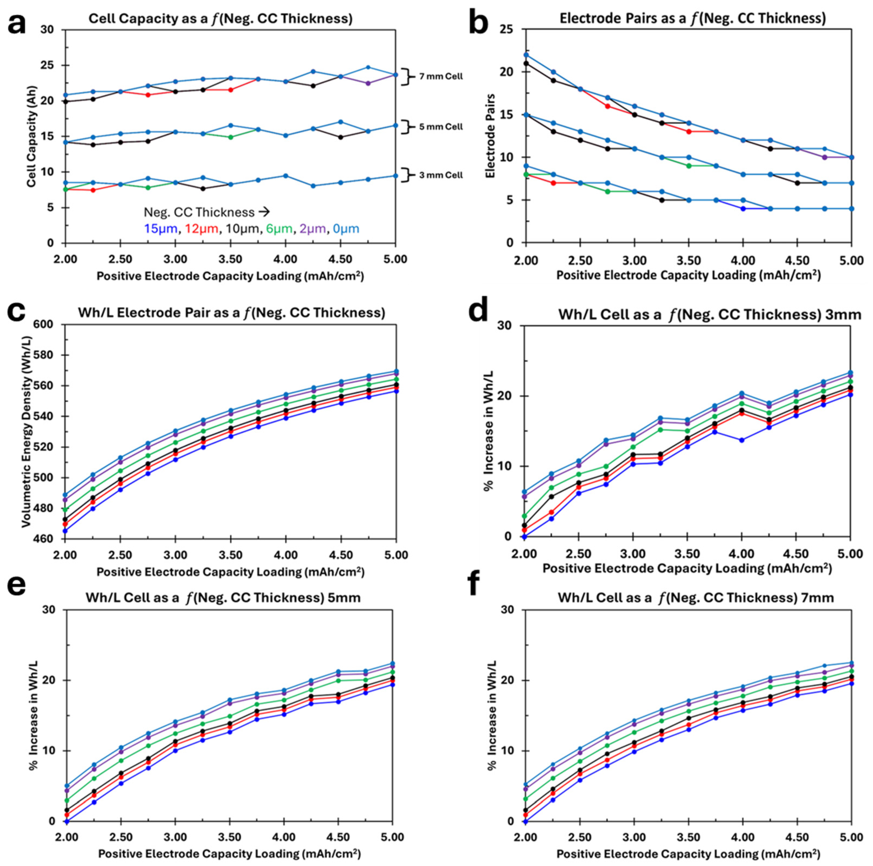
Like the previously presented positive current collector results, the negative current collector has a similar but smaller impact on the cell properties, Figure 3a–f. Negative current collector ranges from 15 µm to 0 µm. Lithium–ion stacked plate cell designs have one more negative current collector in each design when compared to positive current collectors, due to the two single-sided, top and bottom negative electrodes, but the thickness change evaluated in the negative current collector is less than that of the positive. When looking at Figure 3a,b, at a fixed positive electrode capacity loading, with certain designs, when the negative current collector thickness is decreased, an extra electrode pair can fit in the specific cell designs, resulting in a step change in cell capacity. Also, for example, a 3 mm thick cell, between 3.5 mAh cm−2 and 5.00 mAh cm−2, no change in cell capacity or electrode pairs is observed for any negative current collector thickness. Related to Figure 3c, at 2.00 mAh cm−2, volumetric energy density increased by 24 Wh/L as negative current collector thickness is decreased, or 5.2%, while at 5.00 mAh cm−2, a 2.3% rise in single pair volumetric energy density is observed for the range of negative current collector thickness. Figure 3d–f again illustrates the percentage increase in cell volumetric energy density for each cell thickness. Similar results are noted between the negative and positive current collector results. For a 3.0 mm cell thickness and 2.00 mAh cm−2, as the negative current collector thickness is decreased from 15 µm to 0 µm, there is a 6.4% increase in cell volumetric energy density. While for a 5.00 mAh cm−2 capacity loading, the cell volumetric energy density is increased by 3.1%. As cell thickness increases (see Figure 3e,f), the shape of the curve approaches that of Figure 3c. With thicker cell designs, the current collector thickness has a smaller effect on the step changes in electrode pairs or cell capacity, and the increase in volumetric energy density is related to a decrease in overall stack or cell thickness.

3.3. Impact of Separator Thickness

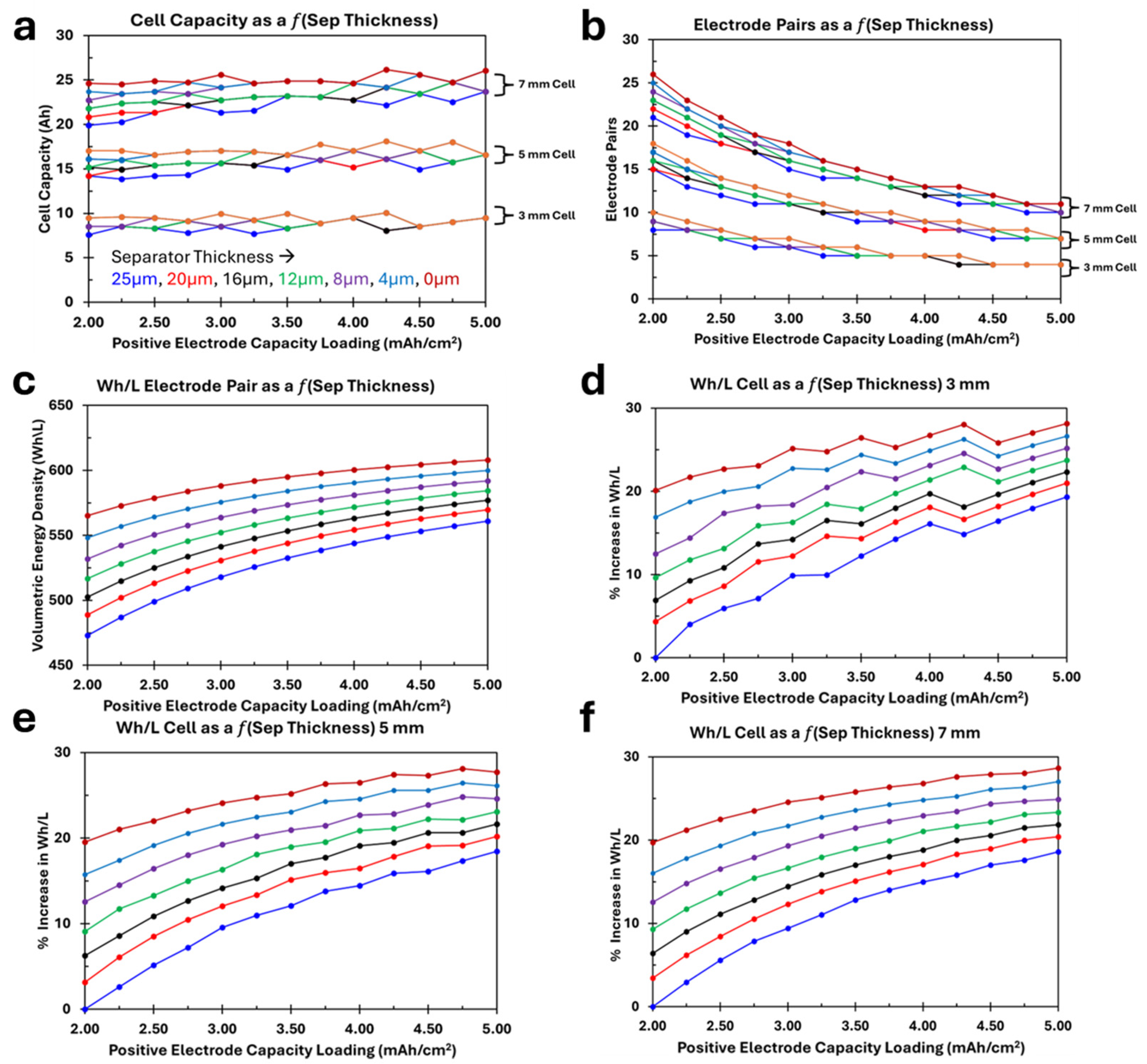
Figure 4 shows the impact of separator thickness on cell properties. The thicknesses of the separators evaluated range from 25 µm to 0 µm, and each electrode pair contains two layers of separator material. The impact of the separator on the cell properties, especially volumetric energy density, is the greatest for the various inert materials evaluated. For Figure 4a,b, the impact is not as observable. Very similar cell properties are noted when comparing cell capacity and electrode pairs related to positive current collector, negative current collector, and separator thickness. At low-capacity loadings, 2.00 mAh cm−2, as separator thickness is decreased from 25 µm to 0 µm, electrode pair volumetric energy density (Figure 4c) is increased by 92 Wh/L or 19.5%, and at the high-capacity loading, an 8.3% increase is noted for the same thickness change. Similar results are noted in Figure 4d–f, where at low-capacity loadings an approximately 20% increase in volumetric energy density is noted.

3.4. Impact of Aluminum Laminate Cell Package Thickness

The range of aluminum laminate package thicknesses evaluated ranges from 156 µm to 0 µm, with the understanding that a 0 µm thick package is unrealistic and used for evaluation purposes only. This is the greatest range of all materials evaluated, and only two layers of laminate package material are included for each cell thickness calculation. Little impact is observed between package thickness and cell capacity or electrode pairs, other than the periodic step changes, where a decrease in package thickness allows for an increase in electrode pairs and cell capacity, similar to the separator and current collector impact previously evaluated. Unlike previous figures, Figure 5c does not show the single electrode pair volumetric energy density, as cell package thickness would have no effect on this property, resulting in overlapping lines. Instead, Figure 5c shows the volumetric energy density for a 7.00 mm thick packaged cell for the various package thicknesses evaluated. For Figure 5c–f an inverse relationship is observed compared to the previously evaluated materials. For positive current collector, negative current collector, and separator thickness, the greatest increase in energy density was observed where the greatest number of electrode pairs occurred, which is either high cell thickness and/or low-capacity loading. Since cell packages are independent of electrode pairs or overall cell thickness, the package thickness is a greater percent of overall cell thickness for thinner cells. This is clear in Figure 5d–f. For a 3.0 mm thick cell with a capacity loading of 2.00 mAh cm−2, a 13.2% increase in volumetric energy density is noted. For a 5.0 mm thick cell, the increase is 7.1% and for a 7.0 mm thick cell, the increase is 5.1%. Also observed is the increase in volumetric energy density change at higher capacity loadings for all cell thicknesses. This is a result of electrode pair thickness and overall cell thickness limitations. For example, for a 3.0 mm cell thickness, at lighter capacity loadings, each electrode pair is thinner. This means that it is easier for the sum of these thin electrode pairs to get closer to 3.0 mm without going over the maximum thickness. While at heavier loadings, each electrode pair is relatively thick. This means that the actual cell thickness for a 3.00 mm thick cell with lighter loadings is thicker and closer to 3.0 mm than a cell designed to be 3.00 mm with heavier loadings.

4. Conclusions

With the need to increase lithium–ion cell capacity and energy density for continued and accelerated adoption of portable electronics and electric vehicles, new active materials continue to be developed and evaluated. Aside from active material development, inert materials used in commercial lithium–ion cells also contribute to cell design characteristics. In the academic world, these inert materials are often overlooked as a crucial component in cell design. It is not until prototypes or commercial cells are manufactured that the importance of these materials is fully understood. Although the presented results are applied to an LCO/Graphite electrode pairing, one would expect similar results to other electrode pairs with relatively similar specific capacities and densities, where the electrode pair thicknesses do not change. If Silicon or SiOx negative materials are incorporated in the negative electrode as active components, the results may not be as straightforward as these extremely high-capacity active materials, which result in very thin negative electrode loadings. As new, higher-capacity active materials are used, typically, more electrode pairs fit into a specific cell thickness, increasing the impact and importance of inert materials.
The impact of positive current collector thickness, negative current collector thickness, separator thickness, and package thickness should not be overlooked as contributing factors in commercial lithium–ion cell design. Decreasing the thickness of these materials while also maintaining a safe and manufacturable cell should continue to be an area of interest for continued development.

Author Contributions

Conceptualization, W.Y. and K.N.; methodology, W.Y.; formal analysis, W.Y.; investigation, W.Y.; writing—original draft preparation, W.Y.; writing—review and editing, K.N. and B.B.; All authors have read and agreed to the published version of the manuscript.

Funding

Work has been partially supported by the Penn State Hazleton Research Development Grant.

Data Availability Statement

The data presented in this study are available on request from the corresponding author due to privacy and restrictions.

Conflicts of Interest

The authors declare no conflicts of interest.

References

  1. Sharma, H.; Sharma, S.; Mishra, P.K. A Critical Review of Recent Progress on Lithium Ion Batteries: Challenges, Applications, and Future Prospects. Microchem. J. 2025, 212, 113494. [Google Scholar] [CrossRef]
  2. Nitta, N.; Wu, F.; Lee, J.T.; Yushin, G. Li-Ion Battery Materials: Present and Future. Mater. Today 2015, 18, 252–264. [Google Scholar] [CrossRef]
  3. Niu, H.; Zhang, N.; Lu, Y.; Zhang, Z.; Li, M.; Liu, J.; Song, W.; Zhao, Y.; Miao, Z. Strategies toward the Development of High-Energy-Density Lithium Batteries. J. Energy Storage 2024, 88, 111666. [Google Scholar] [CrossRef]
  4. Xie, J.; Lu, Y.C. A Retrospective on Lithium-Ion Batteries. Nat. Commun. 2020, 11, 2499. [Google Scholar] [CrossRef] [PubMed]
  5. Liu, J.; Zhang, Y.; Zhou, J.; Wang, Z.; Zhu, P.; Cao, Y.; Zheng, Y.; Zhou, X.; Yan, C.; Qian, T. Advances and Prospects in Improving the Utilization Efficiency of Lithium for High Energy Density Lithium Batteries. Adv. Funct. Mater. 2023, 33, 2302055. [Google Scholar] [CrossRef]
  6. Feng, Y.; Zhou, L.; Ma, H.; Wu, Z.; Zhao, Q.; Li, H.; Zhang, K.; Chen, J. Challenges and Advances in Wide-Temperature Rechargeable Lithium Batteries. Energy Environ. Sci. 2022, 15, 1711–1759. [Google Scholar] [CrossRef]
  7. Scrosati, B.; Garche, J. Lithium Batteries: Status, Prospects and Future. J. Power Sources 2010, 195, 2419–2430. [Google Scholar] [CrossRef]
  8. Schipper, F.; Erickson, E.M.; Erk, C.; Shin, J.-Y.; Chesneau, F.F.; Aurbach, D. Review—Recent Advances and Remaining Challenges for Lithium Ion Battery Cathodes. J. Electrochem. Soc. 2017, 164, A6220–A6228. [Google Scholar] [CrossRef]
  9. Divakaran, A.M.; Minakshi, M.; Bahri, P.A.; Paul, S.; Kumari, P.; Divakaran, A.M.; Manjunatha, K.N. Rational Design on Materials for Developing next Generation Lithium-Ion Secondary Battery. Prog. Solid State Chem. 2021, 62, 100298. [Google Scholar] [CrossRef]
  10. Singh, M.; Kaiser, J.; Hahn, H. Effect of Porosity on the Thick Electrodes for High Energy Density Lithium Ion Batteries for Stationary Applications. Batteries 2016, 2, 35. [Google Scholar] [CrossRef]
  11. Singh, M.; Kaiser, J.; Hahn, H. Thick Electrodes for High Energy Lithium Ion Batteries. J. Electrochem. Soc. 2015, 162, A1196–A1201. [Google Scholar] [CrossRef]
  12. Yourey, W. Cell Design Considerations and Impact on Energy Density—A Practical Approach to EV Cell Design. World Electr. Veh. J. 2023, 14, 279. [Google Scholar] [CrossRef]
  13. Zheng, H.; Li, J.; Song, X.; Liu, G.; Battaglia, V.S. A Comprehensive Understanding of Electrode Thickness Effects on the Electrochemical Performances of Li-Ion Battery Cathodes. Electrochim. Acta 2012, 71, 258–265. [Google Scholar] [CrossRef]
  14. Kim, Y.; Kim, M.; Lee, T.; Kim, E.; An, M.; Park, J.; Cho, J.; Son, Y. Investigation of Mass Loading of Cathode Materials for High Energy Lithium-Ion Batteries. Electrochem. Commun. 2023, 147, 107437. [Google Scholar] [CrossRef]
  15. Choi, J.; Son, B.; Ryou, M.-H.; Kim, S.H.; Ko, J.M.; Lee, Y.M. Effect of LiCoO2 Cathode Density and Thickness on Electrochemical Performance of Lithium-Ion Batteries. J. Electrochem. Sci. Technol. 2013, 4, 27–33. [Google Scholar] [CrossRef]
  16. Malifarge, S.; Delobel, B.; Delacourt, C. Experimental and Modeling Analysis of Graphite Electrodes with Various Thicknesses and Porosities for High-Energy-Density Li-Ion Batteries. J. Electrochem. Soc. 2018, 165, A1275–A1287. [Google Scholar] [CrossRef]
  17. Shim, J.; Striebel, K.A. The Dependence of Natural Graphite Anode Performance on Electrode Density. J. Power Sources 2004, 130, 247–253. [Google Scholar] [CrossRef]
  18. Mu, G.; Agrawal, S.; Sittisomwong, P.; Bai, P. Impacts of Negative to Positive Capacities Ratios on the Performance of Next-Generation Lithium-Ion Batteries. Electrochim. Acta 2022, 406, 139878. [Google Scholar] [CrossRef]
  19. Kim, C.S.; Jeong, K.M.; Kim, K.; Yi, C.W. Effects of Capacity Ratios between Anode and Cathode on Electrochemical Properties for Lithium Polymer Batteries. Electrochim. Acta 2015, 155, 431–436. [Google Scholar] [CrossRef]
  20. Zhu, P.; Gastol, D.; Marshall, J.; Sommerville, R.; Goodship, V.; Kendrick, E. A Review of Current Collectors for Lithium-Ion Batteries. J. Power Sources 2021, 485, 229321. [Google Scholar] [CrossRef]
  21. He, L.P.; Sun, S.Y.; Song, X.F.; Yu, J.G. Recovery of Cathode Materials and Al from Spent Lithium-Ion Batteries by Ultrasonic Cleaning. Waste Manag. 2015, 46, 523–528. [Google Scholar] [CrossRef]
  22. Mahmud, S.; Rahman, M.; Kamruzzaman, M.; Ali, M.O.; Emon, M.S.A.; Khatun, H.; Ali, M.R. Recent Advances in Lithium-Ion Battery Materials for Improved Electrochemical Performance: A Review. Results Eng. 2022, 15, 100472. [Google Scholar] [CrossRef]
  23. Matsumoto, F.; Fukunishi, M. Review of Current Collector-, Binder-, Conductive Additive-Free, and Freestanding Electrodes in Lithium and Related Batteries. Batteries 2024, 10, 330. [Google Scholar] [CrossRef]
  24. Johnson, B.A.; White, R.E. Characterization of Commercially Available Lithium-Ion Batteries. J. Power Sources 1998, 70, 48–54. [Google Scholar] [CrossRef]
  25. Li, J.; Fleetwood, J.; Hawley, W.B.; Kays, W. From Materials to Cell: State-of-the-Art and Prospective Technologies for Lithium-Ion Battery Electrode Processing. Chem. Rev. 2022, 122, 903–956. [Google Scholar] [CrossRef]
  26. Hao, H.; Tan, R.; Ye, C.; Low, C.T.J. Carbon-Coated Current Collectors in Lithium-Ion Batteries and Supercapacitors: Materials, Manufacture and Applications. Carbon. Energy 2024, 6, e604. [Google Scholar] [CrossRef]
  27. Lee, H.; Yanilmaz, M.; Toprakci, O.; Fu, K.; Zhang, X. A Review of Recent Developments in Membrane Separators for Rechargeable Lithium-Ion Batteries. Energy Environ. Sci. 2014, 7, 3857–3886. [Google Scholar] [CrossRef]
  28. Rajan, D.; Kannan, R.; Terala, K.; Moss, P.L.; Weatherspoon, M.H. Analysis of the Separator Thickness and Porosity on the Performance of Lithium-Ion Batteries. Int. J. Electrochem. 2018, 2018, 1925708. [Google Scholar] [CrossRef]
  29. Horváth, D.V.; Tian, R.; Gabbett, C.; Nicolosi, V.; Coleman, J.N. Quantifying the Effect of Separator Thickness on Rate Performance in Lithium-Ion Batteries. J. Electrochem. Soc. 2022, 169, 030503. [Google Scholar] [CrossRef]
  30. Choi, S.; Kim, U.; Roh, Y.; Dzakpasu, C.B.; Lim, J.; Song, M.; Rhee, J.; Lee, Y.S.; Lee, Y.M. Roll-to-Roll Fabrication and Characterization of Ultra-Thin Ceramic-Coated Separator for High-Energy-Density Lithium-Ion Batteries. J. Power Sources 2024, 623, 235427. [Google Scholar] [CrossRef]
  31. Yoo, S.; Hong, C.; Chong, K.T.; Seul, N. Analysis of Pouch Performance to Ensure Impact Safety of Lithium-Ion Battery. Energies 2019, 12, 2865. [Google Scholar] [CrossRef]
  32. Yourey, W. Theoretical Impact of Manufacturing Tolerance on Lithium-Ion Electrode and Cell Physical Properties. Batteries 2020, 6, 23. [Google Scholar] [CrossRef]
  33. Yourey, W. Silicon Negative Electrodes—What Can Be Achieved for Commercial Cell Energy Densities. Batteries 2023, 9, 576. [Google Scholar] [CrossRef]
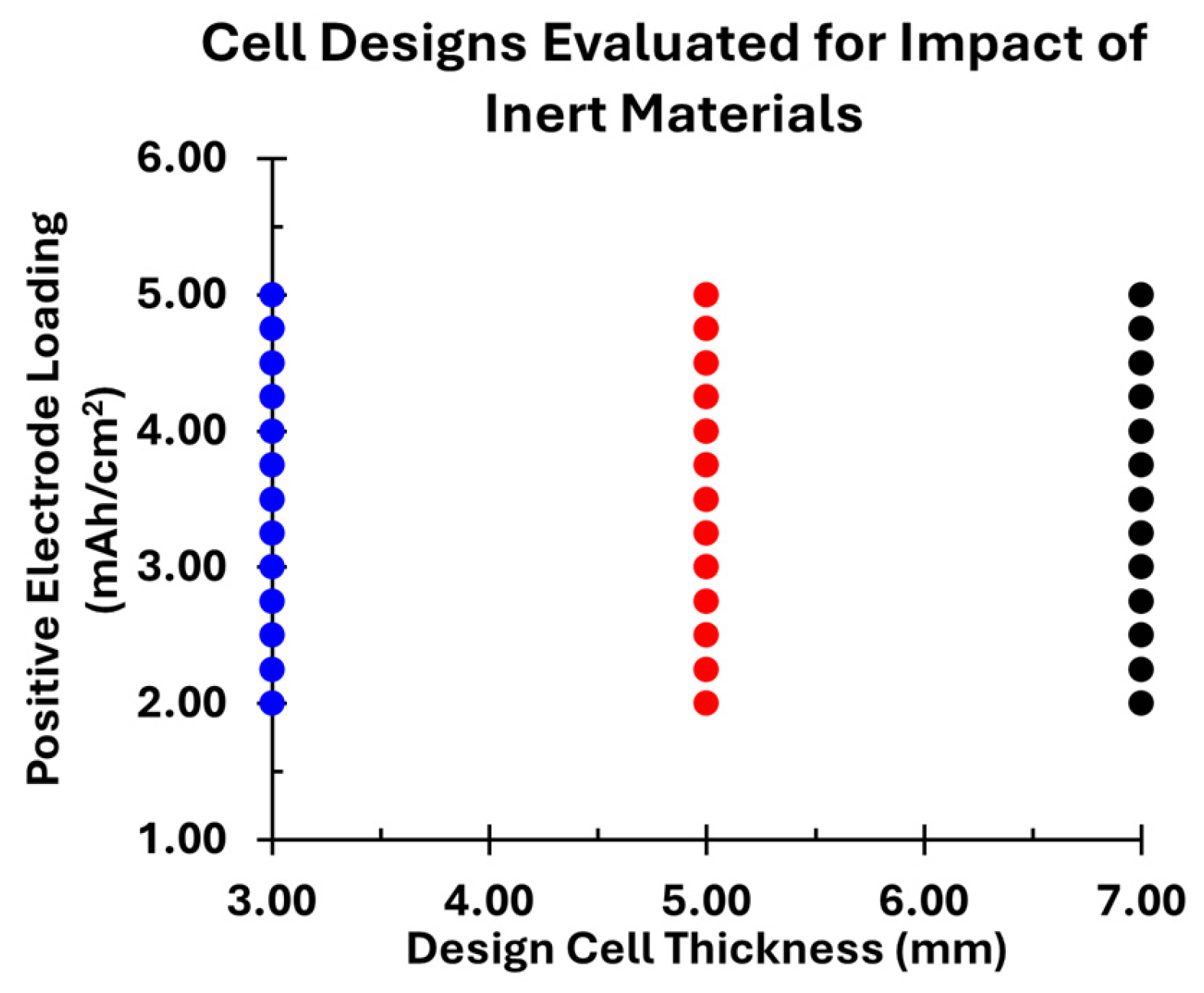
Figure 1. Graphical representation of the different electrode cell designs evaluated. Cell design thickness evaluated for cells with maximum thicknesses of 3.0 mm, 5.0 mm, and 7.0 mm. Positive electrode capacity loading ranged from 2.00 mAh cm−2 to 5.00 mAh cm−2 in 0.25 mAh cm−2 increments.
Batteries 11 00353 g001
Figure 2. Impact of Positive Current Collector thickness on lithium–ion cell characteristics. (a) cell capacity as a function of current collector thickness, electrode loading, and overall cell thickness. (b) electrode pairs as a function of current collector thickness, electrode loading, and overall cell thickness. (c) Wh/L of a single electrode pair as a function of current collector thickness and electrode loading. (df) percentage increase in volumetric energy density as a function of current collector thickness, electrode loading, and overall cell thickness.
Batteries 11 00353 g002
Figure 3. Impact of Negative Current Collector thickness on lithium–ion cell characteristics. (a) cell capacity as a function of current collector thickness, electrode loading, and overall cell thickness. (b) electrode pairs as a function of current collector thickness, electrode loading, and overall cell thickness. (c) Wh/L of a single electrode pair as a function of current collector thickness and electrode loading. (df) percentage increase in volumetric energy density as a function of current collector thickness, electrode loading, and overall cell thickness.
Batteries 11 00353 g003
Figure 4. Impact of separator thickness on lithium–ion cell characteristics. (a) cell capacity as a function of separator thickness, electrode loading, and overall cell thickness. (b) electrode pairs as a function of separator thickness, electrode loading, and overall cell thickness. (c) Wh/L of a single electrode pair as a function of separator thickness and electrode loading. (df) percentage increase in volumetric energy density as a function of separator thickness, electrode loading, and overall cell thickness.
Batteries 11 00353 g004
Figure 5. Impact of aluminum laminate package thickness on lithium–ion cell characteristics. (a) cell capacity as a function of package thickness, electrode loading, and overall cell thickness. (b) electrode pairs as a function of package thickness, electrode loading, and overall cell thickness. (c) Wh/L of 7 mm thick cell as a function of package thickness and electrode loading. (df) percentage increase in volumetric energy density as a function of package thickness, electrode loading, and overall cell thickness.
Batteries 11 00353 g005
Table 1. Positive and negative electrode formulations [32].
Positive Electrode (LCO)
MaterialWeight PercentDensity (g/cm3)
LiCoO2905.00
Conductive Additive52.00
PVDF Electrode Binder51.78
Positive Mixture-4.29
Negative Electrode
MaterialWeight PercentDensity (g/cm3)
Active Carbon902.20
Conductive Additive22.00
PVDF Electrode Binder81.78
Negative Mixture-2.15
Table 2. Inert Materials and Thicknesses Evaluated in Cell Designs.
MaterialThicknesses Evaluated (µm)
Positive Current Collector20, 16, 12, 8, 4, 0
Negative Current Collector15, 12, 10, 6, 2, 0
Separator25, 20, 16, 12, 8, 4, 0
Package Material156, 150, 125, 100, 75, 50, 25, 0
Table 3. Fixed components for inert material investigation [12].
ComponentDimensions
Negative Electrode200 mm × 120 mm
Positive Electrode199 mm × 119 mm
Separator 1201.75 mm × 120 mm
1 Overall separator dimensions are used for stack length and width for stack energy density calculations.
Disclaimer/Publisher’s Note: The statements, opinions and data contained in all publications are solely those of the individual author(s) and contributor(s) and not of MDPI and/or the editor(s). MDPI and/or the editor(s) disclaim responsibility for any injury to people or property resulting from any ideas, methods, instructions or products referred to in the content.