Abstract
SiO2 has a much higher theoretical specific capacity (1965 mAh g−1) than graphite, making it a promising anode material for lithium-ion batteries, but its low conductivity and volume expansion problems need to be improved urgently. In this work, pompon mum-like SiO2/C nanospheres with the sandwich and porous nanostructure were obtained by using dendritic fibrous nano silica (DFNS) and glucose as matrix and carbon source, respectively, through hydrothermal, carbonization and etching operations. The influence of SiO2 content and porous structure on its electrochemical performance was discussed in detail. The final results showed that the C/DFNS-6 with a SiO2 content of 6 wt% exhibits the best electrochemical performance as a negative electrode material for lithium-ion batteries due to its optimal specific surface area, porosity, and appropriate SiO2 content. C/DFNS-6 displays a high specific reversible capacity of 986 mAh g−1 at 0.2 A g−1 after 200 cycles, and 529 mAh g−1 at a high current density (1.0 A g−1) after 300 cycles. It also has excellent rate capability, with a reversible capacity that rises from 599 mAh g−1 to 1066 mAh g−1 when the current density drops from 4.0 A g−1 to 0.2 A g−1. These SiO2/C specific pompon mum-like nanospheres with excellent electrochemical performance have great research significance in the field of lithium-ion batteries.
1. Introduction
Given the escalating global challenges like climate change, environmental risks, and energy resource limitations, it is imperative to aggressively advance energy storage technologies and curtail carbon emissions through reduced reliance on fossil fuels to foster sustainable global energy progress. Lithium-ion batteries (LIBs) are characterized by their high energy density, high power density, and long cycle performance [1,2,3,4], so they have been entrusted with a heavy responsibility in the field of electric vehicles, energy storage, consumer electronics and other fields [5,6].
It is widely recognized that the anode materials significantly influence the energy storage and release processes in lithium-ion batteries [7,8,9]. Graphite anode, which is widely used at present, is quite mature in preparation technology, but the low theoretical specific capacity (372 mAh g−1) of graphite has posed challenges in meeting the market demand for high-capacity LIBs [9,10]. On the flip side, silicon has garnered interest as an anode material due to its higher specific capacity (4200 mAh g−1). Unfortunately, the process of preparing nano silicon, which usually involves several steps and complex manufacturing processes, is fairly complicated, and the high cost also makes the practical application of silicon unfavorable [11,12,13].
In recent years, researchers have conducted extensive research on silicon oxide negative electrode materials, which exhibit good cycling stability compared to Si elemental materials [14,15]. Among them, SiO2 has become a much sought-after alternative material because of its electrochemical properties comparable to silicon. Due to its low discharge voltage (0.2 V vs. Li+/Li), substantial Li-ion storage capacity (1965 mAh g−1), excellent cycling stability and widespread availability, SiO2 is regarded as a promising environmentally friendly Li-ion anode material [16,17,18]. However, improving its poor electrical conductivity and unsatisfactory rate performance is still not less challenging. To this end, compounding with highly conductive carbon materials has proven to be a promising method for enhancing electron transport and mitigating volume changes [19]. Subsequently, SiO2/C composites with different morphologies have been prepared and used as anode materials for LIBs, with nanosphere morphology accounting for the majority [20,21,22,23]. Li et al. successfully prepared dual-porosity structure SiO2/C nanospheres composites, which can obtain a reversible capacity of 635.7 mAh g−1 by cycling 200 times at a current density of 0.1 A g−1, and also demonstrated good multiplicity performance [24]. In addition, Pang et al. synthesized SiO2@carbon composite nanorods with core–shell structure using a simple method of in situ capping polydopamine, which achieved a reversible capacity of 690 mAh g−1 at a current density of 0.1 A g−1, and even at a high 1.0 A g−1 current density, a capacity of 344.9 mAh g−1 can be achieved [25]. Moreover, Zhang et al. used ZIF-8 as a template to design nanocubes SiO2/C composites with an initial discharge capacity of 863.6 mAh g−1 at a current density of 0.1 A g−1, and the reversible capacity was stabilized after 150 cycles at 723 mAh g−1 [26]. Among these many morphologies, SiO2/C composites containing voids offer space to accommodate the mechanical strain, enabling SiO2 to expand without pulverization during the intercalation and deintercalation process of lithium-ion, thus contributing to the formation of a relatively stable structure [27], and such SiO2/C composites exhibit excellent electrochemical properties even with reduced silica content. For example, Chen et al. prepared lemon-like hollow silica spheres as an anode material for LIBs using the soft template method, and the sample at about 56% SiO2 content had a discharge mass specific capacity of 786 mA h g−1 after 500 cycles at a current density of 1.0 A g−1 [21]. Liu et al. prepared SiO2@C hollow spheres by a sacrificial template method, in which the charge/discharge specific capacity was 653.4/649.6 mAh g−1 after 160 cycles at a SiO2 content of 67 wt% and a current density of 0.11 mA cm−2 [28].
In this work, an advanced SiO2/C anode material with pompon mum-like morphology and sandwich porous nanostructure is prepared by hydrothermal, carbonization and etching process, which selects dendritic fibrous nano silica (DFNS) and glucose as the matrix and the carbon source. This pompon mum-like SiO2/C composite anode provides a large number of reaction sites due to its huge specific surface area, and the carbon layer coating on the surface of SiO2 acts as a protective layer, not only inhibiting the repeated growth of the solid electrolyte phase (SEI), but also providing good conductivity. The existence of pores in the pompon mum-like SiO2/C nanospheres leaves a cache space to accommodate the volume expansion of SiO2. Therefore, this novel pompon mum-like SiO2/C nanospheres give excellent cycling stability and rate performance.
2. Materials and Methods
2.1. Materials
All chemical reagents utilized in these experiments are of analytical grade and employed without purification. All aqueous solutions are formulated using deionized water. Cetyltrimethylammonium bromide (CTAB) was from Shanghai Sinopharm Chemical Reagent Co., Ltd., China. Urea, tetraethyl orthosilicate (TEOS), 1-Pentanol, toluene, NaOH and HF were acquired from Shenzheng Xilong Scientific Co., Ltd., China. P-xylene and (3-Aminopropyl) triethoxysilane (APTS) were obtained from Shanghai Macklin Biochemical Co., Ltd.,China. Glucose was provided by Shantou Xilong Chemical Co., Ltd., China.
2.2. Preparation of Pompon Mum-like SiO2/C Nanospheres
In the preparation of pompon mum-like SiO2/C nanospheres, dendritic fibrous nano silica (DFNS) was first prepared according to the methods in the literature [29]. Then, 0.3 g of DFNS, 1.3 g of glucose, 16 mL of distilled water and 4 mL of ethanol were homogeneously mixed and encapsulated into a 50 mL hydrothermal reactor at 195 °C for 40 h to obtain a brown solid precipitate. The obtained solid precipitate was washed up by filtration three times with deionized water and three times with ethanol, in turn, and then dried in an oven at 80 °C for 12 h, put into the tube furnace, heated up to 850 °C at a rate of 3 °C per minute under nitrogen and held for 1 h to obtain a pompon mum-like SiO2/C composite with 50% content of SiO2, which are named C/DFNS-50. The C/DFNS-50 was then corroded with 10% HF solution for 5 h, 10 h and 20 h to obtain other SiO2/C composites with 10%, 6% and 1% content of SiO2, respectively, which are named C/DFNS-10, C/DFNS-6 and C/DFNS-1, respectively. Taking C/DFNS-6 as an example, the fabrication process of pompon mum-like SiO2/C nanospheres is shown in Scheme 1.
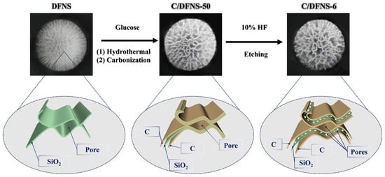
Scheme 1.
Schematic of the preparation route of C/DFNS nanocomposites.
2.3. Materials Characterization
The surface morphologies of the samples were examined using scanning electron microscopy (SEM, S4800, Hitachi High-Tech, Japan) and transmission electron microscopy (JEM-2100F, JEOL Ltd., Japan), and the TEM/energy-dispersive spectroscopy mapping was carried out on the transmission electron microscope to analyze the elements in the samples. The crystal structures of the products were analyzed using the X-ray diffraction (X’Pert PRO, 2θ = 10–80, PANalytical B.V., The Netherlands) method. The Raman spectra were obtained using a Raman microscope (DXR, 532 nm laser, Thermo Fisher Scientific, USA). The content of SiO2 in the sample was measured using a thermogravimetric analyzer (STA-449, NETZSCH Scientific Instruments Trading Ltd., Germany), with a measurement temperature ranging from room temperature to 800 °C and an airflow rate of 5 °C/min. X-ray photoelectron spectroscopy (XPS) analyses were conducted using an ESCALAB 250Xi (Thermo Fisher Scientific, USA). Nitrogen adsorption and desorption isotherms were obtained at 77 K using a NOVA 1200e (Quantachrome Instruments, USA) analyzer.
2.4. Electrochemical Measurements
The electrode components used in this experiment include active materials, acetylene black, and polyvinylidene fluoride adhesive, mixed in a mass ratio of 5:3:2. A small amount of 1-Methyl-2-pyrrolidinone was added dropwise for grinding, and then coated on copper foil. The electrolyte used in this experiment was composed of dissolving ethylene carbonate (EC), dimethyl carbonate (DMC) and diethyl carbonate (DEC) in 1 M LiPF6 in a 1:1:1 volume ratio. A cyclic voltammetry (CV) test and electrochemical impedance spectroscopy (EIS) test of coin cell 2025 were performed by the CHI-760D electrochemical workstation. A Neware GCD testing system was used for constant current charging and discharging testing.
3. Results and Discussion
3.1. Morphology and Structure of Composite Materials
The morphology and structure of DFNS and SiO2/C composites can be analyzed using SEM and TEM. As shown in Figure 1, both the pure DFNS (Figure 1a1,a2) and SiO2/C composites are nanospheres with diameters of about 500~600 nm and can be visualized as a pompon mum-like porous structure. In addition, the C/DFNS-50 (Figure 1b1,b2) obtained by the reaction of DFNS with glucose, as well as the C/DFNS-6 (Figure 1c1,c2) and C/DFNS-1 (Figure 1d1,1d2) obtained by corrosion of C/DFNS-50, are relatively uniformly sized nanospheres, and all three of them do not have any significant difference from pure DFNS.
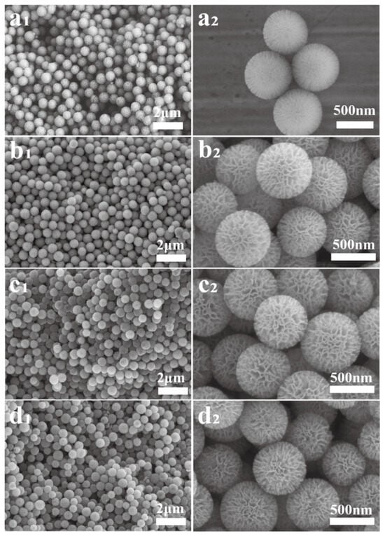
Figure 1.
SEM images of (a1,a2) DFNS, (b1,b2) C/DFNS-50, (c1,c2) C/DFNS-6 and (d1,d2) C/DFNS-1.
The structure differences among these four samples can be clearly seen from their TEM images in Figure 2. As shown in Figure 2a1,a2, DFNS has a dendritic fiber structure that diverges from the center to the edge, and the fibers have the characteristics of being dense in the middle and sparse at the edges. However, from Figure 2b1,b2, it can be seen that the C/DFNS-50 composite no longer shows an obvious fiber structure, which is highly likely due to being covered by a carbon layer. Compared with C/DFNS-50, C/DFNS-10 (Figure 2c1,c2), C/DFNS-6 (Figure 2d1,d2) and C/DFNS-1 (Figure 2e1,e2), nanospheres have obvious traces of corrosion in the center and edges, and the corroded area of C/DFNS-1 is the largest because of the extension of corrosion time. The EDS elemental mappings of C/DFNS-6 (Figure 2f) show that the C element is uniformly distributed in this composite, indicating that DFNS has successfully completed the recombination with carbon. And it is also clear that the content of Si and O elements significantly decreases in the corroded area. This is because the fiber structure of DFNS improves the accessibility of the inner surface of DFNS, and glucose-based carbon can smoothly contact the interior of DFNS to achieve complete coating without changing its pompon mum-like structure [30]. Combining Figure 1 and Figure 2, it is clear that the process of corrosion with HF can successfully corrode part of the DFNS without breaking the structure of the carbon layers.
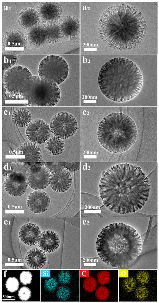
Figure 2.
TEM images of (a1,a2) DFNS, (b1,b2) C/DFNS-50, (c1,c2) C/DFNS-10, (d1,d2) C/DFNS-6, (e1,e2), C/DFNS-1 and (f) EDS elemental mappings of Si (blue), C (red) and O (yellow) for the C/DFNS-6.
The XRD patterns are shown in Figure 3a to elucidate the structural and compositional characteristics of the samples. From the XRD spectrum of DFNS, a broad peak appears near 22°, indicating the characteristic peak of amorphous silicon dioxide [31]. Two broad peaks near 24° and 44° on the curves of C/DFNS-50, C/DFNS-10, C/DFNS-6 and C/DFNS-1 correspond to the (002) and (100) planes of amorphous carbon, respectively, indicating the presence of amorphous carbon in the four composite samples [32]. In particular, in the XRD spectra of the four composites, there is an overlap between the characteristic peak of SiO2 at 22° and the characteristic peak of carbon at 24° [27]. This indicates that amorphous carbon has been combined with the DFNS material after reacting with glucose. The intensity of the two carbon peaks of C/DFNS-50 in XRD patterns is lower than that of C/DFNS-10, C/DFNS-6 and C/DFNS-1, which is due to the relatively low carbon content in C/DFNS-50.

Figure 3.
(a) XRD patterns of DFNS, C/DFNS-50, C/DFNS-10, C/DFNS-6 and C/DFNS-1, (b) Raman spectrum and (c) TG curves of C/DFNS-50, C/DFNS-10, C/DFNS-6 and C/DFNS-1.
In the Raman spectra of the four composites (Figure 3b), the characteristic peaks at 1340 and 1590 cm−1 belong to the disordered induced band (D) and graphite band (G), respectively. The ratio of these two characteristic peaks (ID/IG) represents the degree of graphitization of carbon in the composite material [33]. The ID/IG values of C/DFNS-50, C/DFNS-10, C/DFNS-6 and C/DFNS-1 are 0.9957, 0.9839, 0.9711 and 0.9789, respectively, indicating the smaller ID/IG ratio of C/DFNS-6 contained more defective carbons [20], which can provide lots of vacancies and defects. Research has shown that defective carbon in materials is beneficial for improving their electrochemical performance [20,33,34]. The characteristic of C/DFNS-6 not only accelerates the diffusion of lithium-ion, but also provides reversible sites for lithium-ion storage.
As shown in Figure 3c, thermal gravimetric analysis (TGA) was performed to determine the mass loading of SiO2 among the SiO2/C composites. During the entire combustion testing process, all the samples experienced significant weight loss within the temperature range of 440 °C to 620 °C, which is related to the release of carbon oxides [34]. Subsequently, the weight of the four samples remained stable above 620 °C, which is the content of SiO2 in the composites. C/DFNS-50, C/DFNS-10, C/DFNS-6 and C/DFNS-1 show mass loss around 50 wt%, 90 wt%, 94 wt% and 99 wt%, respectively, suggesting the residual amounts of SiO2 were 50 wt%, 10 wt%, 6 wt% and 1 wt%, respectively. The carbon content of C/DFNS-50 is lower than that of the C/DFNS-10, C/DFNS-6 and C/DFNS-1, which is consistent with XRD analysis results. Combined with the EDS elemental mapping of C/DFNS-6 in Figure 2f, it can be inferred that the residual SiO2 is found uniformly distributed in this composite material, which is beneficial for stabilizing the structure of C/DFNS-6 and enhancing the stability of anode material structure [24].
In order to investigate the surface electronic states and elemental composition of C/DFNS-6 with the highest defective carbon content, it can be analyzed by XPS in Figure 4. Figure 4a shows the full XPS spectrum of C/DFNS-6, where the characteristic peaks at 104, 285 and 533 eV correspond to Si 2p, C 1s and O 1s, respectively, indicating the presence of Si, C and O elements in the C/DFNS-6 [35,36]. Among them, the XPS fine spectrum of C 1s fitted three characteristic peaks, located at 284.8, 285.6 and 288.5 eV, respectively, corresponding to the C=O, C-C and C=O bonds (Figure 4b) [37]. Figure 4c shows the XPS fine spectrum of Si 2p, the characteristic peak at 103.3 eV, corresponding to Si4+ [26], which indicates that the Si element in the C/DFNS-6 existed in the form of SiO2. The O 1s spectrum shown in Figure 4d is divided into two peaks, with peaks near 533.1 and 531.3 eV corresponding to Si-O and C-O bonds [21,26], respectively, which corroborates the successful composite of carbon layers.
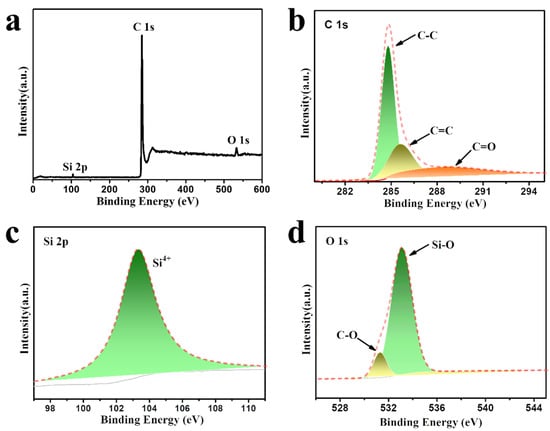
Figure 4.
(a) XPS survey spectrum and high-resolution XPS spectra for (b) C 1s, (c) Si 2p and (d) O 1s of the C/DFNS-6.
Detailed analysis of the specific surface area and pore structure of DFNS, C/DFNS-50, C/DFNS-6 and C/DFNS-1 using the N2 adsorption/desorption analysis method. As shown in Figure 5, the adsorption/desorption isotherms displayed by DFNS (Figure 5a), C/DFNS-50 (Figure 5b), C/DFNS-6 (Figure 5c) and C/DFNS-1 (Figure 5d) are both I/IV type, with obvious hysteresis loops, indicating the presence of micropores as well as mesopores inside the samples [23]. Table 1 shows the Brunauer–Emmett–Teller (BET) specific surface area of the DFNS, C/DFNS-50, C/DFNS-10, C/DFNS-6 and C/DFNS-1 is 223, 127, 573, 672 and 651 m2 g−1, respectively. And their pore sizes are all distributed in the range of 1.7–15.6 nm, which are confirmed by the pore size distribution graphs inset in Figure 5a–d. The total pore volumes of DFNS, C/DFNS-50, C/DFNS-10, C/DFNS-6 and C/DFNS-1 are 0.33, 0.06, 0.46, 0.64 and 0.60 cm3 g−1, respectively, and the average pore sizes are 5.43, 4.18, 3.47, 3.52 and 3.48 nm, respectively. It is clear that C/DFNS-50 obtained after successful loading of the carbon layer by DFNS has the smallest specific surface area and pore volume, while C/DFNS-6 obtained after corrosion of SiO2/C composites for 10 h has the largest specific surface area and porosity, which may give C/DFNS-6 more exposed active sites and electrolyte diffusion channels. Therefore, the etching time of 10 h can make C/DFNS composites have the best specific surface area and porosity, which is expected to achieve the rapid transport of Li+ and electrons [38].
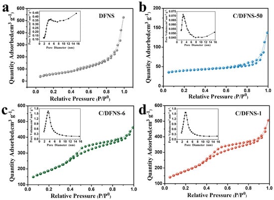
Figure 5.
BET parameter values and pore size distribution curve of (a) DFNS, (b) C/DFNS-50, (c) C/DFNS-6 and (d) C/DFNS-1.

Table 1.
BET parameter values for DFNS, C/DFNS-50, C/DFNS-10, C/DFNS-6 and C/DFNS-1.
3.2. Electrochemical Performances
The reaction kinetics and electrochemical activity of the prepared electrodes can be investigated by various electrochemical methods as follows. The cycle performances and coulombic efficiency of the prepared electrode materials are investigated in Figure 6a,b. Compared with only 130 mAh g−1 for DFNS, the composites of C/DFNS-50, C/DFNS-10, C/DFNS-6 and C/DFNS-1 display a higher capacity of 521, 776, 986 and 600 mAh g−1 after 200 cycles at 0.2 A g−1, respectively. The initial coulombic efficiencies of DFNS, C/DFNS-50, C/DFNS-10, C/DFNS-6 and C/DFNS-1 is 35.4%, 43.0%, 40.3%, 44.0% and 42.3%, respectively. All of the four SiO2/C composites show a significant period of capacity decay during the early stages of cycling, presumably due to the loss of lithium-ions caused by the electrode materials indicating the formation of an SEI layer. In addition, it can be seen that throughout the entire cycle life, the capacity of the carbon-coated DFNS anode is higher than that of the original DFNS anode, indicating that carbon coating plays an important role in improving the electrochemical performance of anode materials [39]. From the previous TGA analysis, it can be seen that C/DFNS-50 and C/DFNS-10 have higher SiO2 content (50 wt% and 10 wt%, respectively), but their extremely small specific surface area and pore volume (Table 1) not only hinder the transport of Li+, but also have insufficient space to buffer the volume expansion of SiO2. On the contrary, C/DFNS-1 has a larger specific surface area and pore volume, but the extremely low SiO2 content (1 wt%) also limits the improvement of the specific capacity. For the case of C/DFNS-6, due to its suitable SiO2 content (6 wt%), the largest specific surface area and pore volume, and rich porous structure, ensures structural stability while greatly improving the specific capacity of the material, resulting in optimal cycling performance [24].
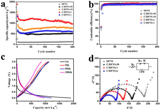
Figure 6.
(a) Cycling performance and (b) coulombic efficiency at 0.2 A g−1 of DFNS, C/DFNS-50, C/DFNS-10, C/DFNS-6 and C/DFNS-1, (c) galvanostatic charge/discharge profiles of C/DFNS-6, (d) EIS spectra of DFNS, C/DFNS-50, C/DFNS-6 and C/DFNS-1.
Figure 6c shows the discharge/charge profiles of the C/DFNS-6 electrode under different cycles at a current density of 0.2 A g−1 in the voltage range of 0.01~3.0 V. Evidently, the discharge capacities during the fifth and fiftieth cycles are lower compared to the first cycle mainly. This is primarily due to the SEI film formation process during the initial cycle, which consumes a significant quantity of lithium-ions, leading to a higher irreversible capacity.
EIS tests in the frequency range of 105~0.1 Hz can be conducted to study the electrical conductivity of DFNS, C/DFNS-50, C/DFNS-6 and C/DFNS-1. Figure 6d shows the Nyquist plots of the four electrode materials, including the equivalent circuit model. In this Nyquist plot, the high-frequency semicircle corresponds to the charge transfer resistance (Rct) between the electrode and electrolyte interface, while the low-frequency diagonal corresponds to the lithium-ion diffusion resistance in the electrode [40]. The semicircle in the curve of C/DFNS-6 is much smaller, and the curve is approximately vertical at low frequencies, indicating a decrease in Rct and good capacitance behavior. The curve of C/DFNS-6 has a smaller semicircle diameter in the high-frequency region, indicating a smaller Rct and good capacitance characteristics [27,40]. Specifically, the Rct of C/DFNS-6 is only 81 Ω, which is much lower compared with 230 Ω, 166 Ω and 120 Ω for DFNS, C/DFNS-50 and C/DFNS-1, respectively. This further confirms that C/DFNS-6 has efficient interfacial charge transfer and electronic conduction capabilities [39,40].
The CV curves of C/DFNS-6 at a scanning rate of 0.1 mV s−1 between 0.01 and 3.0 V are shown in Figure 7. During the cathodic polarization process of the initial cycle, two distinct cathodic peaks were observed at 1.42 V and 0.54 V and then disappeared in the following cycles. A cathodic peak was observed between 1.3 and 1.5 V, which is caused by the reduction and decomposition of the electrolyte and the irreversible formation of the SEI layer on the surface of the negative electrode material [27]. In addition, the peak appearing around 0.5~0.7 V corresponds to the formation of the SEI layer in the electrolyte, the reaction between SiO2 and Li+, and the generation of Si and a series of lithium silicates. (see reaction Equations (1)–(3)) [40,41,42,43], and these non-electrochemically active substances such as Li2O and Li2Si2O5 are uniformly distributed on the SiO2 particles, buffering the volume expansion of SiO2, which is beneficial for maintaining the stability of the negative electrode material structure and improving the cycling life of lithium-ion batteries [22]. As shown in Equation (4) [42], the anodic peak at 0.01 V is related to the alloying reaction of Si and Li+. As shown in Equation (5), the anodic characteristic peak at 0.25 V is related to the LixSi dealloying reaction [42]. During the subsequent scanning, the CV curves of C/DFNS-6 almost overlapped, indicating that the reactions were reversible after the first cycle.
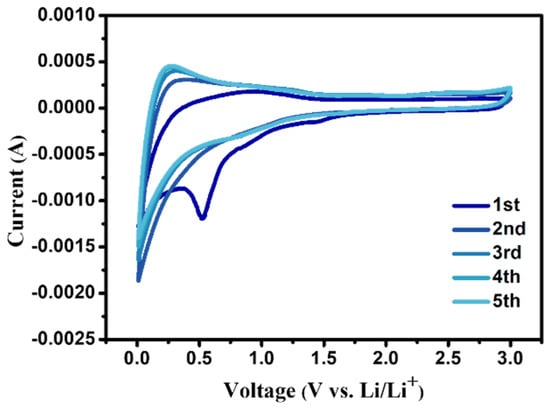
Figure 7.
Cyclic voltammetry curves of C/DFNS-6 at a scan rate of 0.5 mV s−1.
2 SiO2 + 4 Li+ + 4 e− → Li4SiO4 + Si
SiO2 + 4 Li+ + 4 e− → 2 Li2O + Si
5 SiO2 + 4 Li+ + 4 e− → 2 Li2Si2O5 + Si
Si + x Li+ + x e− → LixSi
LixSi → Si + x Li+ + x e−
The rate capability of three SiO2/C composites was investigated with the current density increased from 0.2 A g−1 to 4 A g−1 (Figure 8a). Compared with C/DFNS-50 and C/DFNS-1, C/DFNS-6 exhibits a superior rate capability at different current densities. Specifically, C/DFNS-6 delivers reversible discharge capacities of 1015, 856, 799, 769, 708, 670 and 599 mAh g−1 at the current densities of 0.2, 0.4, 0.6 0.8, 1.0, 2.0 and 4.0 A g−1, respectively. In particular, when the current density drops back to 0.2 A g−1, even after 35 cycles, a high capacity of 1066 mAh g−1 can still be maintained, which demonstrates the coating of the carbon layer and the presence of pores effectively suppresses the repeated destruction and reconstruction of the SEI layer, resulting in excellent stability and rate performance of the C/DFNS-6 electrode material [24,27].
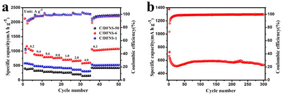
Figure 8.
(a) Rate performance of DFNS, C/DFNS-50, C/DFNS-6 and C/DFNS-1, (b) cycling performance at current density of 1 A g−1 of C/DFNS-6.
In addition, the long-term cycling performance of C/DFNS-6 was further tested at high current density (1.0 A g−1), as shown in Figure 8b. Basically, the initial discharge specific capacity of C/DFNS-6 is 1378 mAh g−1. After that, the capacity decreases slightly until reaching the 25th cycle. Then, due to the gradual activation of silica at high current density, the specific capacity also increases. After 300 cycles, the reversible specific capacity of C/DFNS-6 remained stable at 529 mAh g−1, indicating good cycling performance even at high current densities.
In order to better understand the electrochemical kinetics of pure DFNS and C/DFNS-6 with the highest reversible specific capacity, the CV measurements for both were performed at various scan rates ranging from 1.0 to 5.0 mV s−1 (Figure 9a1,b1). Both samples show similar CV characteristics, i.e., the polarization effect gradually increased with increasing peak current at the scan rate, resulting in a shift of the anodic and cathodic peaks to the high and low potential sides, respectively. The contribution of the capacitive effect can be analyzed based on the relationship between the measured current (i) and scan rate (v) in five sets of CV curves [44]. To this end, Equations (6) and (7) were introduced, where a and b are both empirical parameters [45].
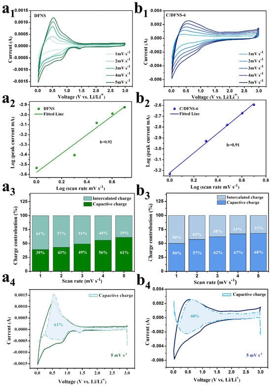
Figure 9.
CV curves of (a1) DFNS and (b1) C/DFNS-6 at different scan rates, log (the cathodic peak current density) vs. log (scan rate) curves of (a2) DFNS and (b2) C/DFNS-6 to estimate the b-value, contribution ratio of the capacitive and diffusion-controlled charge versus scan rate for (a3) DFNS and (b3) C/DFNS-6, the contribution ratio of pseudo-capacitance at 5 mV s−1 for (a4) DFNS and (b4) C/DFNS-6.
i = avb
logi = blogv + loga
i = k1v + k2v1/2
The parameter “b” dictates the extent of capacity contribution from either capacitance or the diffusion-controlled process. Specifically, if b = 0.5, it means that the negative electrode material only has diffusion-control behavior; b = 0.5~1 indicates the coexistence of diffusion-control behavior and pseudocapacitive effect; and b = 1 indicates that it only has a pseudocapacitive effect [32,43]. As shown in Figure 9a2,b2, the b-values of DFNS and C/DFNS-6 are 0.92 and 0.91, respectively, which reveals that the electrochemical processes of these two materials are controlled by these two processes. Subsequently, the contribution ratio of these two processes was accurately studied using Equation (8) [45]. The k1ν and k2ν1/2 represent the contribution rates of capacitance and diffusion-controlled processes, respectively [45]. As shown in Figure 9a3,b3, the capacitance contribution ratio of DFNS gradually increases from 39% to 61% and that of C/DFNS-6 from 50% to 68% with the increase in scanning rate. It can be seen that the capacitance contribution of C/DFNS-6 is higher than that of DFNS at all the same scanning rates, and the larger capacitance contribution is beneficial for the storage of Li+, which may be attributed to the abundant pore structure in C/DFNS-6. The percentage of capacitive control capacity at a sweep rate of 5.0 mV s−1 for DFNS and DFNS-6 are presented in detail in Figure 9a4,b4, respectively.
Similarly, to specifically compare the diffusion of lithium-ions in DFNS and DFNS-6 materials, the Li+ diffusion coefficient (DLi+) of DFNS and C/DFNS-6 electrodes in the first charge/discharge cycle was determined using GITT. As can be seen in Figure 10a, the first charge/discharge time of C/DFNS-6 (65 h) is significantly longer than that of DFNS (20 h), which suggests that the covering of the carbon layers and abundant pores alleviate the volume expansion problem and indeed improve the stability of the C/DFNS-6 structure. In addition, DFNS shows a voltage plateau around 0.7 V, corresponding to the formation of the SEI layer in conventional carbonate electrolytes, which is consistent with the CV analysis results (Figure 7). C/DFNS-6 does not show a significant voltage plateau due to the lower content of SiO2. The DLi+ can be calculated for both materials according to Equation (9) [46]:
where Vm represents the molar volume of the material (cm3 mol−1); mB stands for mass of the active material (g); MB is the molar mass of the active material (g mol−1); S indicates the electrode/electrolyte contact area (cm2); t represents the duration of the current pulse (s); Es represents the voltage change caused by pulse (V); Et is expressed as constant current charge and discharge voltage change (V) [46]. In Figure 10b, the DLi+ of C/DFNS-6 is higher than that of DFNS, with the former fluctuating in the range of 10−10.4 to 10−11.8 and the latter varying in the range of 10−8.2 to 10−9.4, which is due to the excellent specific surface area and pore volume of C/DFNS-6 [47].
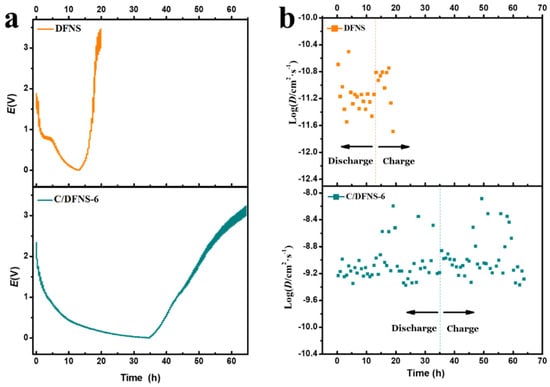
Figure 10.
(a) GITT curve and (b) Li+ diffusion coefficients of DFNS and C/DFNS-6.
Based on the above characterization analysis and electrochemical analysis, we speculate that the outstanding electrochemical performance of DFNS-6 is due to the synergistic effect of the protection of the carbon layers, the porous structure and the appropriate SiO2 content, as shown in Scheme 2. For pure DFNS, although its large specific surface area and pompon mum-like structure provide active sites and transport channels for Li+, direct contact with the electrolyte accelerates the volume expansion and structural collapse, which, in turn, leads to electrode failure. In contrast, C/DFNS-6, protected by the carbon layers, greatly improves the structural stability and electrical conductivity while alleviating the volume expansion problem, the more porous structure therein also accelerates the Li+ transport, and the suitable SiO2 content provides a good capacity basis. Therefore, C/DFNS-6 possesses excellent reversible specific capacity and cycling stability.
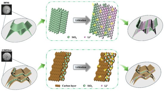
Scheme 2.
Schematic diagram of the working principle of DFNS and C/DFNS-6.
Table 2 compares the electrochemical properties of the C/DFNS-6 obtained in this work with various forms of SiO2/C composite anode materials reported in previous studies. It is clear that C/DFNS-6 outperforms many other SiO2/C composites with different morphologies, which confirms the ingenious design for the anode materials in this work.

Table 2.
Comparison of the lithium-storage performance between SiO2/C composites prepared from different morphologies reported in the literature.
4. Conclusions
In summary, we uniformly coated the carbon layer and retained the unique porous morphology of DFNS through simple hydrothermal, carbonization and etching steps, which significantly enhances the electrical conductivity of the anode material while effectively inhibiting the repeated destruction and reconstruction of the SEI layer and reducing the capacity loss, and a moderate amount of SiO2 provides the basis for high reversible specific capacity of the material, providing a high specific capacity of 986 mAh g−1 after 200 cycles at 0.2 A g−1. The large number of pore structures obtained by corroding part of the DFNS allocate sufficient space to accommodate volume expansion during the reaction process and provide a fast ion transport channel, which gives C/DFNS-6 excellent rate performance and cycling stability, with a capacity of 599 mAh g−1 when the current density is 4.0 A g−1, and 1066 mAh g−1 can be quickly recovered when the current density drops back to 0.2 A g−1. These advantages make C/DFNS-6 a good application prospect in the field of lithium-ion batteries and provide a very meaningful solution for the modification of SiO2-based anode materials.
Author Contributions
X.S. designed a complete experimental process and operated the experiment throughout. X.S., K.G., S.L. and W.D. conducted tests. X.S. and Y.L. conducted data analysis. Y.L. and X.L. provided effective suggestions for improving the experiment. Y.W. and X.L. assisted in the experiment and testing process. X.S. completed the manuscript. K.Z. and A.Q. contributed to experimental concept generation. A.Q. reviewed the writing, performed verification, provided supervision, managed the project, and acquired funding. All authors have read and agreed to the published version of the manuscript.
Funding
This work was supported by the Foundation of Guangxi Science and Technology Programs (2023JJD160032, 2023AB01138 and 2015GXNSFDA139035), the National Natural Science Foundation of China (51564009), and the Innovation Project of Guangxi Graduate Education (YCBZ2021062).
Data Availability Statement
The raw data supporting the conclusions of this article will be made available by the authors on request.
Conflicts of Interest
The authors declare no conflicts of interest.
References
- Sharma, R.; Kumar, H.; Kumar, G.; Sharma, S.; Aneja, R.; Sharma, A.K.; Kumar, R.; Kumar, P. Progress and challenges in electrochemical energy storage devices: Fabrication, electrode material, and economic aspects. Chem. Eng. J. 2023, 468, 143706. [Google Scholar] [CrossRef]
- Obrovac, M.; Christensen, L. Structural changes in silicon anodes during lithium insertion/extraction. Electrochem. Solid-State Lett. 2004, 7, A93. [Google Scholar] [CrossRef]
- Choi, S.; Wang, G. Advanced lithium-ion batteries for practical applications: Technology, development, and future perspectives. Adv. Mater. Technol. 2018, 3, 1700376. [Google Scholar] [CrossRef]
- Nitta, N.; Wu, F.; Lee, J.; Yushin, G. Li-ion battery materials: Present and future. Mater. Today 2015, 18, 252–264. [Google Scholar] [CrossRef]
- Liu, C.; Li, F.; Ma, L.; Cheng, H.-M. Advanced materials for energy storage. Adv. Mater. 2010, 22, E28–E62. [Google Scholar] [CrossRef] [PubMed]
- Armand, M.; Tarascon, J. Building better batteries. Nature 2008, 451, 652–657. [Google Scholar] [CrossRef] [PubMed]
- Chen, J. Recent progress in advanced materials for lithium ion batteries. Materials 2013, 6, 156–183. [Google Scholar] [CrossRef] [PubMed]
- Balogun, M.; Qiu, W.; Luo, Y.; Meng, H.; Mai, W.; Onasanya, A.; Olaniyi, T.K. A review of the development of full cell lithium-ion batteries: The impact of nanostructured anode materials. Nano Res. 2016, 9, 2823–2851. [Google Scholar] [CrossRef]
- Du, C.; Zhao, Z.; Liu, H.; Song, F.; Chen, L.; Cheng, Y.; Guo, Z. The status of representative anode materials for lithium-ion batteries. Chem. Rec. 2023, 23, e202300004. [Google Scholar] [CrossRef] [PubMed]
- Maurin, G.; Bousquet, C.; Henn, F.; Bernier, P.; Almairac, R.; Simon, B. Electrochemical intercalation of lithium into multiwall carbon nanotubes. Chem. Phys. Lett. 1999, 312, 14–18. [Google Scholar] [CrossRef]
- Yin, Y.; Wan, L.; Guo, Y. Silicon-based nanomaterials for lithium-ion batteries. Chin. Sci. Bull. 2012, 57, 4104–4110. [Google Scholar] [CrossRef]
- Maresca, G.; Sankaran, A.; Santa Maria, L.J.; Ottaviani, M.; Fantini, S.; Ryan, K.M.; Brutti, S.; Appetecchi, G.B. Superior compatibility of silicon nanowire anodes in ionic liquid electrolytes. Energy Mater. 2024, 4, 400017. [Google Scholar] [CrossRef]
- Wang, X.; Niu, C.; Cui, L.; Qiao, F.; Wang, J.; Mai, L. Solution-catalyzed carbothermal reduction of argo-waste SiO2 enables low-temperature and fast synthesis of Si (Ⅱ)-C anode. Chem. Eng. J. 2023, 472, 145116. [Google Scholar]
- Liu, Z.; Wang, X.; Hu, J.; Meng, J.; Niu, C.; Liu, F.; Cui, L.; Yu, R.; Mai, L. High-capacity sub-nano divalent silicon from biosilicification. Adv. Energy Mater. 2023, 13, 2301715. [Google Scholar] [CrossRef]
- Zhang, H.; Hu, R.; Feng, S.; Lin, Z.; Zhu, M. SiO–Sn2Fe@ C composites with uniformly distributed Sn2Fe nanoparticles as fast-charging anodes for lithium-ion batteries. eScience 2023, 3, 100080. [Google Scholar] [CrossRef]
- Tu, J.; Yuan, Y.; Zhan, P.; Jiao, H.; Wang, X.; Zhu, H.; Jiao, S. Straightforward approach toward SiO2 nanospheres and their superior lithium storage performance. J. Phys. Chem. C 2014, 118, 7357–7362. [Google Scholar] [CrossRef]
- Hu, G.; Sun, X.; Liu, H.; Xu, Y.; Liao, L.; Guo, D.; Liu, X.; Qin, A. Improvement of lithium storage performance of silica anode by using ketjen black as functional conductive agent. Nanomaterials 2022, 12, 692. [Google Scholar] [CrossRef]
- Sun, Q.; Zhang, B.; Fu, Z. Lithium electrochemistry of SiO2 thin film electrode for lithium-ion batteries. Appl. Surf. Sci. 2008, 254, 3774–3779. [Google Scholar] [CrossRef]
- Ozen, S.; Eroglu, O.; Karatepe, N. Electrochemically pre-lithiated SiO2@C nanocomposite anodes for improved performance in lithium-ion batteries. Nanotechnology 2023, 34, 485403. [Google Scholar] [CrossRef]
- Li, H.; Wu, X.; Sun, H.; Wang, K.; Fan, C.-Y.; Zhang, L.-L.; Yang, F.-M.; Zhang, J.-P. Dual-porosity SiO2/C nanocomposite with enhanced lithium storage performance. J. Phys. Chem. C 2015, 119, 3495–3501. [Google Scholar] [CrossRef]
- Jiao, M.; Liu, K.; Shi, Z.; Wang, C. SiO2/Carbon composite microspheres with hollow core-shell structure as a high-stability electrode for lithium-ion batteries. ChemElectroChem 2017, 4, 542–549. [Google Scholar] [CrossRef]
- Chen, K.; Tan, Y.; Wang, K.; Niu, J.; Chen, Z.Y. High specific capacity of carbon coating lemon-like SiO2 hollow spheres for lithium-ion batteries. Electrochim. Acta 2022, 401, 139497. [Google Scholar] [CrossRef]
- Cao, X.; Chuan, X.; Massé, R.; Huang, D.; Li, S.; Cao, G. A three layer design with mesoporous silica encapsulated by a carbon core and shell for high energy lithium ion battery anodes. J. Mater. Chem. A 2015, 3, 22739–22749. [Google Scholar] [CrossRef]
- Huang, S.; Yang, D.; Zhang, W.; Qiu, X.; Li, Q.; Li, C. Dual-templated synthesis of mesoporous lignin-derived honeycomb-like porous carbon/SiO2 composites for high-performance Li-ion battery. Microporous Mesoporous Mater. 2021, 317, 111004. [Google Scholar] [CrossRef]
- Pang, H.; Zhang, W.; Yu, P.; Pan, N.; Hu, H.; Zheng, M.; Xiao, Y.; Liu, Y.; Liang, Y. Facile synthesis of core-shell structured SiO2@carbon composite nanorods for high-performance lithium-ion batteries. Nanomaterials 2020, 10, 513. [Google Scholar] [CrossRef] [PubMed]
- Zhang, Z.; Huang, Q.; Ma, W.; Li, H. Interfacial engineering of polyhedral carbon@hollowed carbon@SiO2 nanobox with tunable structure for enhanced lithium ion battery. Appl. Surf. Sci. 2021, 538, 148039. [Google Scholar] [CrossRef]
- Sui, D.; Yao, M.; Si, L.; Yan, K.; Shi, J.; Wang, J.; Xu, C.C.; Zhang, Y. Biomass-derived carbon coated SiO2 nanotubes as superior anode for lithium-ion batteries. Carbon 2023, 205, 510–518. [Google Scholar] [CrossRef]
- Liu, X.; Chen, Y.; Liu, H.; Liu, Z. SiO2@C hollow sphere anodes for lithium-ion batteries. J. Mater. Sci. Technol. 2017, 33, 239–245. [Google Scholar] [CrossRef]
- Maity, A.; Belgamwar, R.; Polshettiwar, V. Facile synthesis to tune size, textural properties and fiber density of dendritic fibrous nanosilica for applications in catalysis and CO2 capture. Nat. Protoc. 2019, 14, 2177–2204. [Google Scholar] [CrossRef]
- Zhu, J.; Yao, C.; Maity, A.; Xu, J.; Zhan, T.; Liu, W.; Sun, M.; Wang, S.; Polshettiwar, V.; Tan, H. Nitrogen doped carbon spheres with wrinkled cages for the selective oxidation of 5-hydroxymethylfurfural to 5-formyl-2-furancarboxylic acid. Chem. Commun. 2021, 57, 2005–2008. [Google Scholar] [CrossRef]
- Haskouri, J.; José, M.; David, O.; Fernández, L.; Latorre, J.; Guillem, C.; Beltrán, A.; Beltrán, D.; Amorós, P. Nanoparticulated silicas with bimodal porosity: Chemical control of the pore sizes. Inorg. Chem. 2008, 47, 8267–8277. [Google Scholar] [CrossRef] [PubMed]
- Zhao, Z.; Das, S.; Xing, G.; Fayon, P.; Heasman, P.; Jay, M.; Bailey, S.; Lambert, C.; Yamada, H.; Wakihara, T.; et al. A 3D organically synthesized porous carbon material for lithium-ion batteries. Angew. Chem. Int. Ed. 2018, 57, 11952–11956. [Google Scholar] [CrossRef] [PubMed]
- Luo, Y.; Li, X.; Hao, X.; Xu, Y.; Tang, S.; Zhang, K.; Qin, A. Few layers 2D MoS2/tubular sisal fiber-derived carbon composite: Enhanced cycling performance as anode material for sodium-ion batteries. J. Energy Storage 2023, 67, 107463. [Google Scholar] [CrossRef]
- Yu, R.; Jiang, R.; Zhou, Z. Yolk-shell SiO2 wrapped by reduced graphene oxide for high performance lithium-ion battery anode. J. Alloys Compd. 2023, 937, 168324. [Google Scholar] [CrossRef]
- Chen, K.; Tan, Y.; Gao, Y. Facile synthesis of pomegranate-like structured SiOx composite spheres with internal carbon conductive network for lithium-ion batteries. J. Power Sources 2023, 581, 233493. [Google Scholar] [CrossRef]
- Shi, C.; Chen, J.; Guo, T.; Luo, G.; Shi, H.; Shi, Z.; Qin, G.; Zhang, L.; He, X. Controllable preparation to boost high performance of nanotubular SiO2@C as anode materials for lithium-ion batteries. Batteries 2023, 9, 107. [Google Scholar] [CrossRef]
- Li, D.; Zhang, X.; Wang, Y.; Zong, P.; Zhang, L.; Zhang, Z.; Gu, X.; Qiao, Y.; Lu, G.; Tian, Y. Adjusting ash content of char to enhance lithium storage performance of rice husk-based SiO2/C. J. Alloys Compd. 2021, 854, 156986. [Google Scholar]
- Liu, H.; Liu, X.; Liu, Z.; Tao, J.; Dai, X.; Yang, Q.; Xua, J.; Shan, Z. Graphite@ silicon embedded in a carbon conformally coated tiny SiO2 nanoparticle matrix for high-performance lithium-ion batteries. Inorg. Chem. Front. 2021, 8, 4395–4406. [Google Scholar] [CrossRef]
- Wang, S.; Zhao, N.; Shi, C.; Liu, E.; He, C.; He, F.; Ma, L. In-situ grown CNTs modified SiO2/C composites as anode with improved cycling stability and rate capability for lithium storage. Appl. Surf. Sci. 2018, 433, 428–436. [Google Scholar] [CrossRef]
- Zhang, L.; Shen, K.; He, W.; Liu, Y.; Guo, S. SiO2@ graphite composite generated from sewage sludge as anode material for lithium ion batteries. Int. J. Electrochem. Sci. 2017, 12, 10221–10229. [Google Scholar] [CrossRef]
- Hao, S.; Wang, Z.; Chen, L. Amorphous SiO2 in tunnel-structured mesoporous carbon and its anode performance in Li-ion batteries. Mater. Des. 2016, 111, 616–621. [Google Scholar] [CrossRef]
- Belgibayeva, A.; Taniguchi, I. Synthesis and characterization of SiO2/C composite nanofibers as free-standing anode materials for Li-ion batteries. Electrochim. Acta 2019, 328, 135101. [Google Scholar] [CrossRef]
- Xu, T.; Wang, Q.; Zhang, J.; Xie, X.; Xia, B. Green synthesis of dual carbon conductive network-encapsulated hollow SiOx spheres for superior lithium-ion batteries. ACS Appl. Mater. Interfaces 2019, 11, 19959–19967. [Google Scholar] [CrossRef] [PubMed]
- Tao, J.; Wang, F.; Han, F.; He, Y.; Zhang, F.; Liu, J. Improving the lithium storage performance of micro-sized SiOx particles by uniform carbon interphase encapsulation and suitable SiO2 buffer component. Electrochim. Acta 2021, 385, 138431. [Google Scholar] [CrossRef]
- Luo, K.; Wu, K.; Hou, Q.; Zhang, W.; Jiang, T.; Wang, X.; Liu, X.; Liu, W. Spider-web-inspired cellulose nanofibrils networking polyaniline-encapsulated silica nanoparticles as anode material of lithium-ion batteries. Carbohydr. Polym. 2022, 277, 118833. [Google Scholar] [CrossRef] [PubMed]
- Dees, D.; Kawauchi, S.; Abraham, D.; Prakash, J. Analysis of the galvanostatic intermittent titration technique (GITT) as applied to a lithium-ion porous electrode. J. Power Sources 2009, 189, 263–268. [Google Scholar] [CrossRef]
- Hu, G.; Liu, H.; Luo, Y.; Zhang, K.; Guo, D.; Liu, X.; Qin, A. Two-dimensional sandwich-like silica@ carbon@ silica nanosheets for superior lithium storage. Mater. Lett. 2022, 308, 131288. [Google Scholar] [CrossRef]
- Yuan, Y.; Wang, S.; Kang, Z.; Jiao, S. Facile synthesis of SiO2/C composite and its application as anode material for lithium ion batde. Electrochemistry 2015, 83, 421–424. [Google Scholar] [CrossRef][Green Version]
- Liang, C.; Chen, Y.; Xu, H.; Xia, Y.; Hou, X.; Gan, Y.; Ma, X.; Tao, X.; Huang, H.; Zhang, J.; et al. Embedding submicron SiO2 into porous carbon as advanced lithium-ion batteries anode with ultralong cycle life and excellent rate capability. J. Taiwan Inst. Chem. Eng. 2019, 95, 227–233. [Google Scholar] [CrossRef]
- Ali, S.; Jaffer, S.; Maitlo, I.; Shehzad, F.K.; Wang, Q.; Ali, S.; Akram, M.Y.; He, Y.; Nie, J. Photo cured 3D porous silica-carbon (SiO2-C) membrane as anode material for high performance rechargeable Li-ion batteries. J. Alloys Compd. 2020, 812, 152127. [Google Scholar] [CrossRef]
- Ren, Y.R.; Yang, B.; Wei, H.M.; Ding, J. Electrospun SiO2/C composite fibers as durable anode materials for lithium ion batteries. Solid State Ion. 2016, 292, 27–31. [Google Scholar] [CrossRef]
Disclaimer/Publisher’s Note: The statements, opinions and data contained in all publications are solely those of the individual author(s) and contributor(s) and not of MDPI and/or the editor(s). MDPI and/or the editor(s) disclaim responsibility for any injury to people or property resulting from any ideas, methods, instructions or products referred to in the content. |
© 2024 by the authors. Licensee MDPI, Basel, Switzerland. This article is an open access article distributed under the terms and conditions of the Creative Commons Attribution (CC BY) license (https://creativecommons.org/licenses/by/4.0/).