Article

Developing Preventative Strategies to Mitigate Thermal Runaway in NMC532-Graphite Cylindrical Cells Using Forensic Simulations

1
WMG, The University of Warwick, Coventry CV4 7AL, UK
2
The Faraday Institution, Quad One, Becquerel Avenue, Harwell Campus, Didcot OX11 0RA, UK
*
Author to whom correspondence should be addressed.
Batteries 2024, 10(3), 104; https://doi.org/10.3390/batteries10030104
Submission received: 31 January 2024 / Revised: 8 March 2024 / Accepted: 10 March 2024 / Published: 15 March 2024
(This article belongs to the Section Battery Performance, Ageing, Reliability and Safety)

Abstract

:
The ubiquitous deployment of Li-ion batteries (LIBs) in more demanding applications has reinforced the need to understand the root causes of thermal runaway. Herein, we perform a forensic simulation of a real-case failure scenario, using localised heating of Li(Ni0.5Mn0.3Co0.2)O2 versus graphite 18650 cylindrical cells. This study determined the localised temperatures that would lead to venting and thermal runaway of these cells, as well as correlating the gases produced as a function of the degradation pathway. Catastrophic failure, involving melting (with internal cell temperatures exceeding 1085 °C), deformation and ejection of the cell componentry, was induced by locally applying 200 °C and 250 °C to a fully charged cell. Conversely, catastrophic failure was not observed when the same temperatures were applied to the cells at a lower state of charge (SOC). This work highlights the importance of SOC, chemistry and heat in driving the thermal failure mode of Ni-rich LIB cells, allowing for a better understanding of battery safety and the associated design improvements.

1. Introduction

Li-ion batteries have become the most convenient source of power for portable electronic applications since their launch in 1991 [1]. Such uses, along with other consumer electronics now commonly using lithium-ion batteries (LIBs), have, however, increasingly received much attention in recent years regarding their safety parameters. They contain a flammable and toxic organic solvent electrolyte that can become gaseous with increases in temperature and lead to cell venting [2,3]. In a worst-case scenario, they can also undergo catastrophic failure through thermal runaway (TR), which causes significant damage to the environment, equipment and people. The prevention of TR has become more vital than ever, as the technology is now pushed to the limits of its power and energy density for some chemistries [4], with LIBs increasingly employing larger cells and format dimensions to achieve higher energy densities. Examples of these include the BYD Blade cell, which is >90 cm in length with a capacity of 202 Ah. As such, the mitigation of TR (or circumnavigating it entirely) has become paramount to ensuring better safety. As temperatures increase, the carbonate electrolyte decomposes and can generate a pressure increase within the battery, causing venting. With further heating, the cell can undergo a thermal runaway (TR) [3]. TR is specifically brought about by a cascade of exothermic chain reactions, which dramatically increase the battery temperature, leading to uncontrollable temperature increases and eventual combustion [5]. Devising a means of reducing or eliminating key exothermic reactions during the early stages of TR is paramount to engineering improved safety into LIBs. Early detection systems have been developed that can now detect unique precursors to TR [6]. Any early detection mode will need to take into account the sequential stages of TR:
The abuse conditions → Gassing → Smoke generation → Fire
From the perspective of fire protection technology, development is needed to monitor real-time early-stage warnings. Whilst one of the functions of a battery management system (BMS) is to monitor the state of health, it cannot monitor and alert users to the early stages of TR [7]. These are typically coupled with printed circuit boards (PCBs) which measure changes in battery voltage, current and temperature. More advanced systems could offer more a predictive early-stage TR capability if analysed more deeply, precisely and with improved hard or soft sensing accompaniments [8]. However, even the “best” PCBs that monitor the voltage and external surface temperature of each cell are not capable of preventing events leading up to TR because they cannot track fast-emerging adverse events in real time [9] which occur over a few seconds [10]. Most LIBs contain a safety vent, which is designed to release the pressure buildup before TR. In cylindrical cells, this vent is in the form of a concave domed disc at the top of the cell, which, in the event of a pressure increase, releases gases into the surroundings. There are a range of safety tests for batteries [11], designed to simulate situations during operation and used as methods to validate safety. These include thermal, mechanical and electrical tests [12]. More specifically, there are environmental tests, such as climate chamber tests, which involve exposing the cell to temperatures up to 150 °C for 10 min; passing the test requires the cell to not vent or undergo catastrophic failure. Given the many applications of batteries, such tests do not cover every operational scenario, such as exposure to localised heating. In fact, only one study was found to cover this scenario using a heat gun [12]. With the drive for smaller but greater-power devices, this could result in poor design of the ancillary electric circuitry, whereby temperatures could exceed 150 °C and for longer than 10 min. The benefit of using forensic simulation approaches for real-format batteries allows us to:
  • Understand complex reaction pathways (with the aid of appropriate additional characterisation)
  • Learn how to suppress TR following the onset of the rapid deterioration of the electrodes and electrolyte.
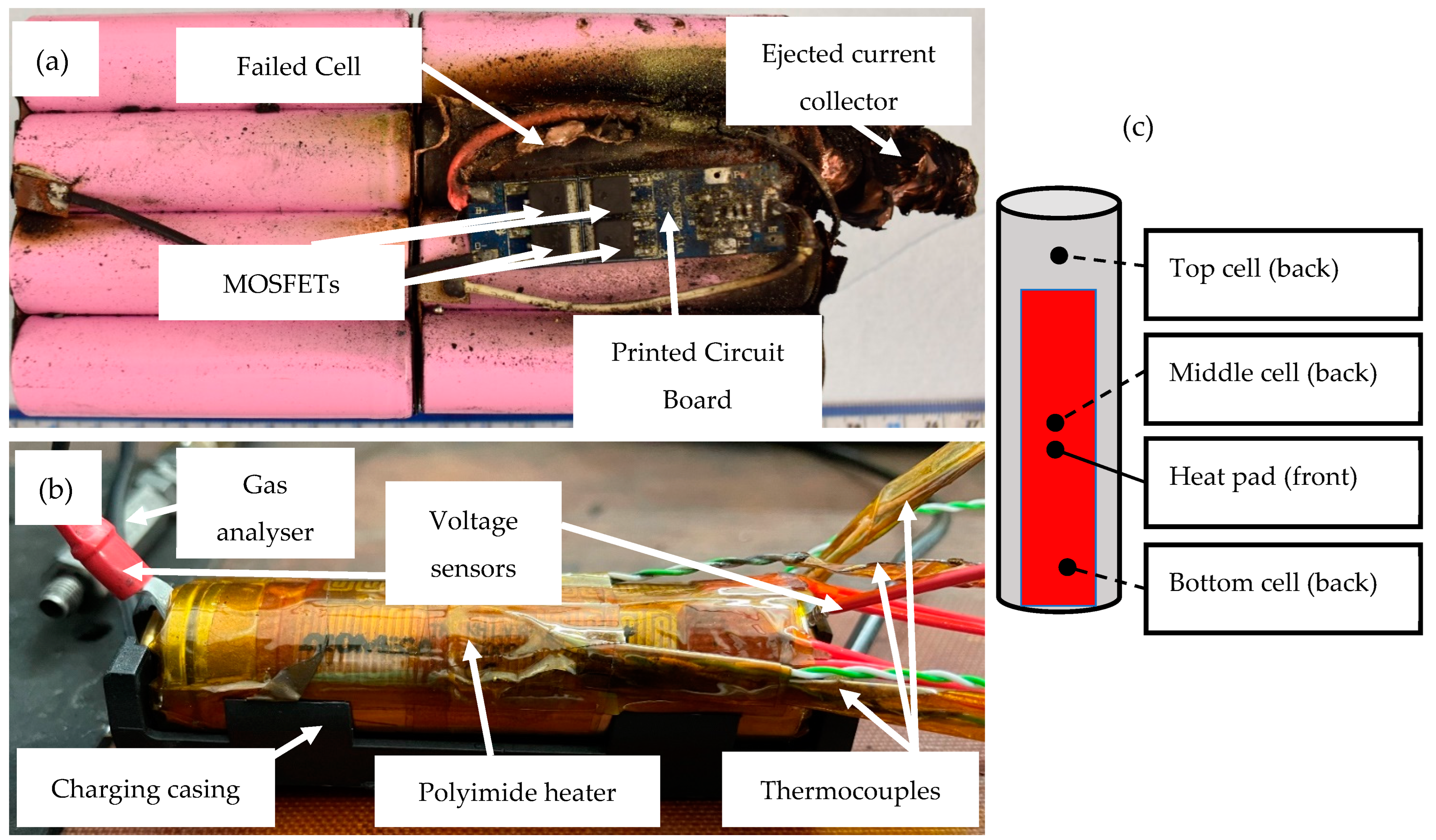
A deeper understanding of 1 can better inform the design and generation of improved materials and chemicals—ones that will better withstand conditions in which accelerated degradation would ordinarily occur.
In addition to temperature, the SOC of a cell also has an impact on the likelihood of thermal runaway, relating to the peak heat flux with a higher SOC [13]. It is actually both the thermal stability of the cathode and the SOC of the anode that are instrumental to the severity of thermal runaway in LIBs [14], with the anode and cathode active materials responsible for generating more heat at a higher SOC [15]. Understanding the effects of the SOC on the aging behaviour in LIBs can serve to extend the service life and also to increase their safer operation. As cells based on NMC532 versus graphite age, a consequence of this is Li inventory depletion, such that the operating voltage of the cathode steadily increases—a phenomenon referred to as electrode slippage [13]. This makes it easier to over-delithiate the cathode at a higher SOC [16]. If too much Li is extracted from the NMC, the crystal structure becomes destabilised and starts to reduce at the particle surface—with resulting oxygen loss and exothermic reactions with the electrolyte [17,18]. On the other electrode side of the cell, the lower cut-off potential is dominated by the anode voltage rise upon delithiation, facilitating an over-discharged condition at a lower SOC [16]. The impact of this is a destabilised solid electrolyte interphase (SEI) [19] and an increased likelihood of gassing and capacity fade.
As the development of higher-energy-density cathode materials (with greater % of Ni) continues, so do the challenges of achieving a greater thermal stability with these materials, a crucial performance and safety parameter. Since Ni can cycle between Ni2+/3+ and Ni3+/4+ redox couples without large variations in voltage, the evolution of higher-Ni NMCs such as NMC532, 622 and, more recently, 811 became possible [20]. This followed the commercial success of the initial development and uptake of NMCs 111 and 333. However, cells based on higher-Ni layered oxides still suffer from a fast capacity decay and low thermal abuse tolerance at higher voltages [21]. The amount of side-reaction products has been observed to increase constantly, corresponding to a greater Ni content [22]. The average TR trigger temperature of NMC532 has been reported to be 244.1 °C [23] and informed the conditions of this study.
Our methodology was chosen to mimic the conditions of a real event, whereby the cylindrical cells were exposed to continual localised heat and charging, which ultimately induced catastrophic failure (this event is summarised in Figure 1). The TR triggering event—dT/dt—for NMC532 is reported as 540.5 °C min−1 (average of 3 cells) [23]. In the situation where the BMS is to prevent TR by activating a rapid cooling mechanism, an early-stage detection method is required to detect exotherms or alternatively to detect gas release in real time.
Here, we demonstrate using forensic reconstruction how a low SOC facilitates venting only (with applied temperatures up to 250 °C), while a high SOC facilitates venting and thermal runaway (at a lower applied temperature, 200 °C). TR results in internal temperatures greater than 1000 °C. We go further by demonstrating that at a high SOC, it is possible to avoid TR onset at venting by rapidly removing the heat source.

2. Experiments

Sets of three commercial LG 18650 cylindrical cells (nominal capacity 2.2 Ah and based on graphite–NMC532 chemistry) were tested under two conditions. These involved a cell heating and charging test (henceforth referred to as a low-SOC test) and a charged cell heating test (henceforth referred to as a high-SOC test), respectively. The low-SOC test involved charging the cells from 0% SOC to 100% SOC using a C/3 CC and then a CV to C/30. Whilst charging was undertaken, the cells had constant temperatures of 100 °C, 150 °C, 200 °C or 250 °C applied to localised areas for 3 h. The high-SOC test involved maintaining the cells at 100% SOC and applying constant temperatures of 100 °C, 150 °C, 200 °C and 250 °C to a localised area for 3 h. Under both conditions, the tests were stopped if the cell underwent catastrophic failure.
All testing was carried out in an abuse test chamber set at 25 °C, with temperatures monitored using K-type thermocouples (TCs) connected to a Pico (TC-08) data logger. The cell voltage was monitored using a voltage sensor (TC-08 single channel terminal board). Cell charging and characterisation was carried out using a Maccor 4200 battery cycler. Localised heating was provided using an Omega polyimide flexible film heater (12.7 mm wide × 50.8 mm long and rated at 10 W). The heating temperature was further controlled using a proportional integral derivative (PID) controller based on an Arduino board. The controller regulated the supplied current to the heater so that the programmed temperatures were 100 °C, 150 °C, 200 °C and 250 °C. Figure 1 shows a module failure situation from an internal case study using similar cells and an experimental setup to emulate a failure situation.
The gases generated during testing were monitored using a Hiden gas analyser based on quadrupole mass spectroscopy (QMS). Measurements was taken in real time, with the equipment nozzle placed approximately 15 mm from the positive end of the cell, where the cell is known to house safety devices such as the current interrupt device (CID) and positive temperature coefficient (PTC) device.
CT scans were carried out using a ZEISS METROTOM scanner set to a resolution of 31 µm; the CT reconstruction software used was METROTOM OS (Version 3.2, Carl Zeiss, Oberkochen, Germany). X-ray Micro CT is a kind of non-destructive testing (NDT) using X-ray radiographs with 360° rotations, creating a 3D volume and allowing the visualisation of the internal structure of the cell [24]. The radiographs are then reconstructed using METROTOM OS to generate the rendered volume.
Cross-sections of the cells were prepared using standard metallurgical techniques and etched using 1% Nital solution for 5 s. Optical micrographs were taken using a Nikon Eclipse LV150N microscope. The mechanical properties were obtained according to hardness testing, performed using a Wilson VH3300 Automatic Hardness Tester. Vickers micro-hardness tests were carried out with a load of 0.1 kg and a dwell time of 15 s.

3. Results and Discussion

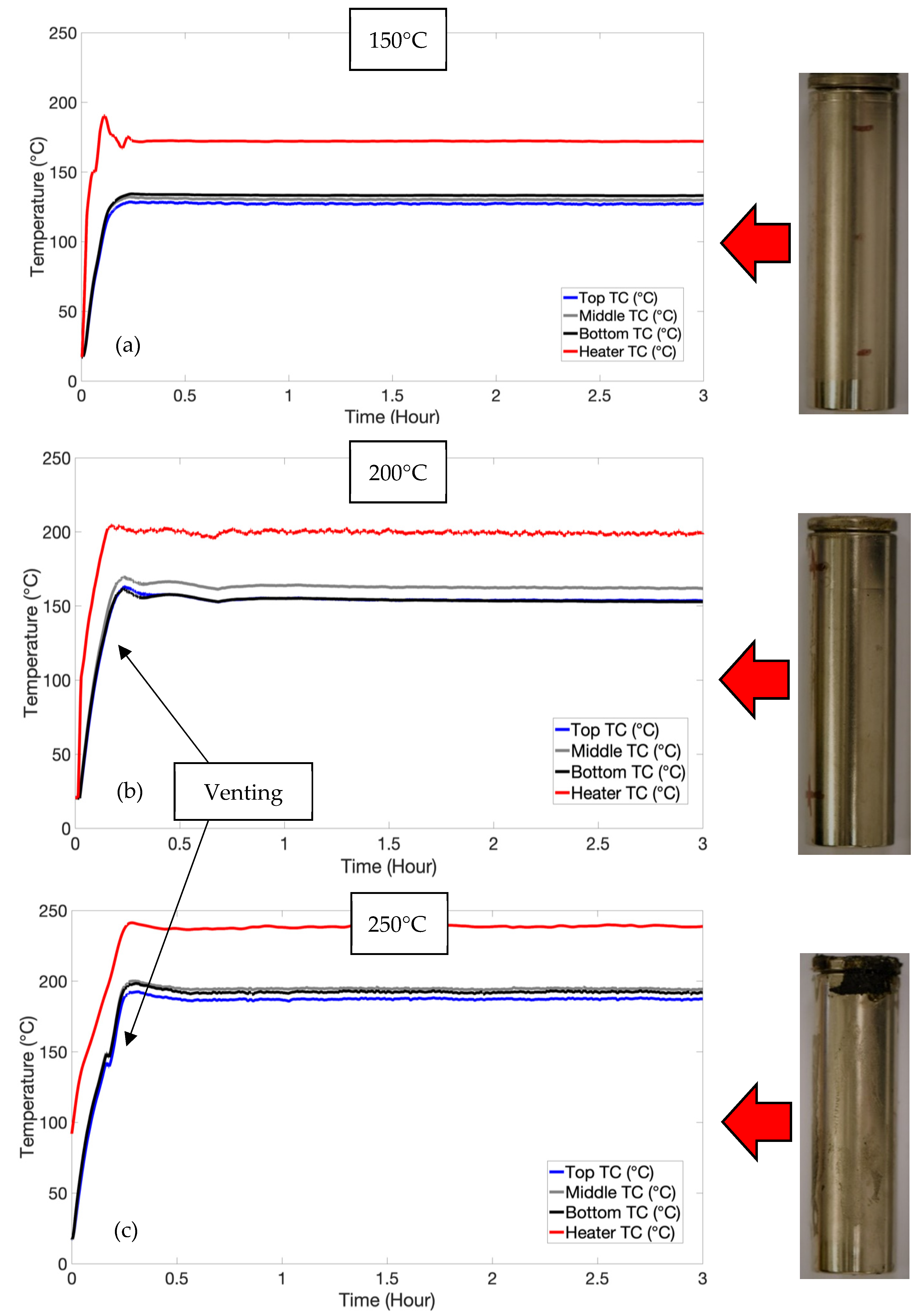
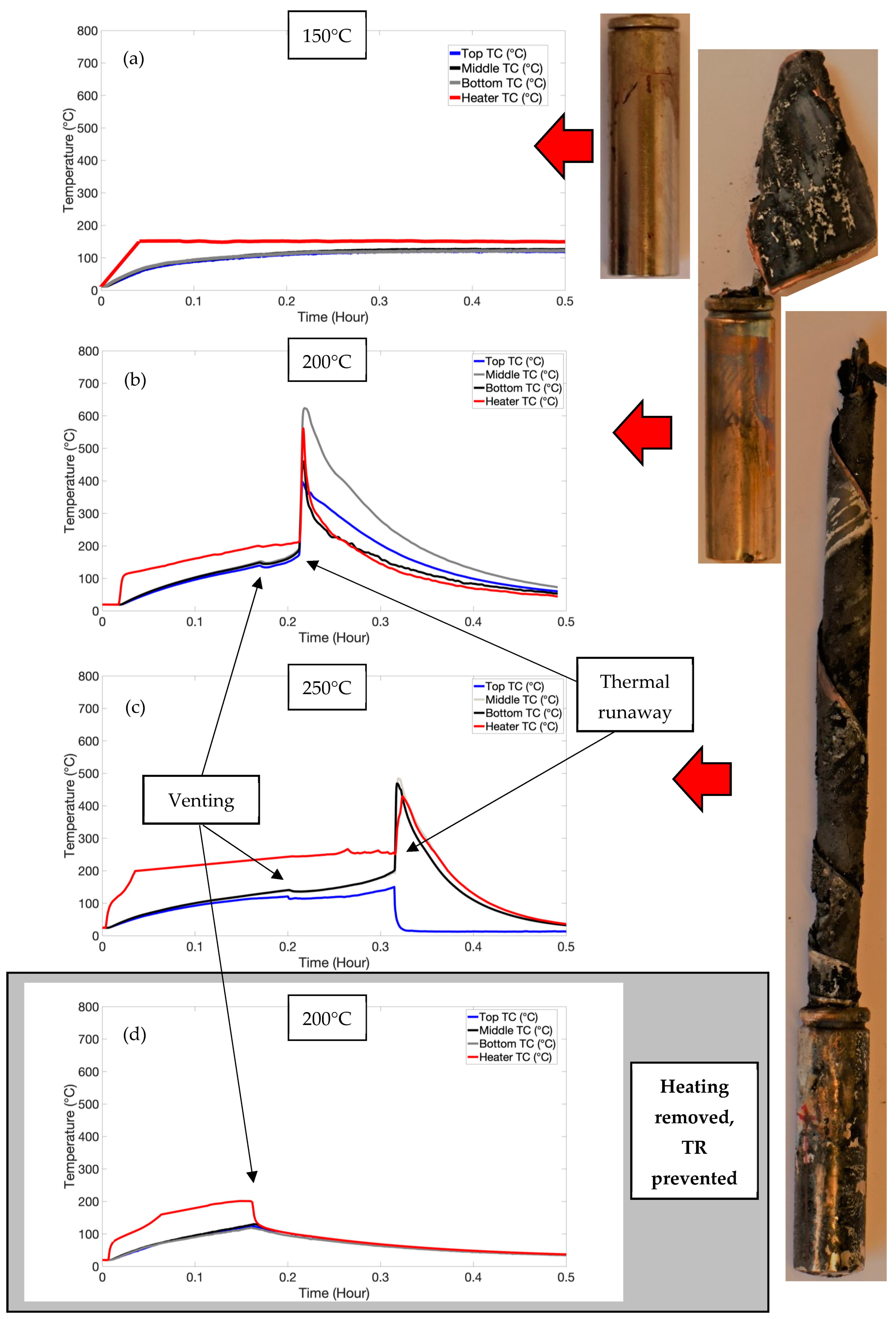
3.1. Temperature-Induced Venting without Thermal Runaway: Low-SOC Regime

A summary of the thermal events observed in the low-SOC testing is shown in Table 1. Venting can be identified by the temperatures logged during testing and has been identified according to the Joule–Thomson cooling effect [25]. This is due to a change in temperature that accompanies the expansion of a gas without the production of work or the transfer of heat.
The low-SOC test did not induce thermal runaway and only resulted in venting. Figure 2 shows the typical temperatures measured during testing. As can be seen, all cells were heated until the cells reached an equilibrium temperature, whereby the rate of heat dissipation exceeded the rate of heat generation applied to the cell. The 200 °C and 250 °C samples were vented at an SOC of 6% and 7%, respectively. This was based on charging the cells at C/3 at the same time as heating, causing venting. Cells at a high SOC are tied to higher fire hazards, having more intense reactions and (flammable) gas generation [26]. Furthermore, increasing the SOC increases the volume of gases released [27].

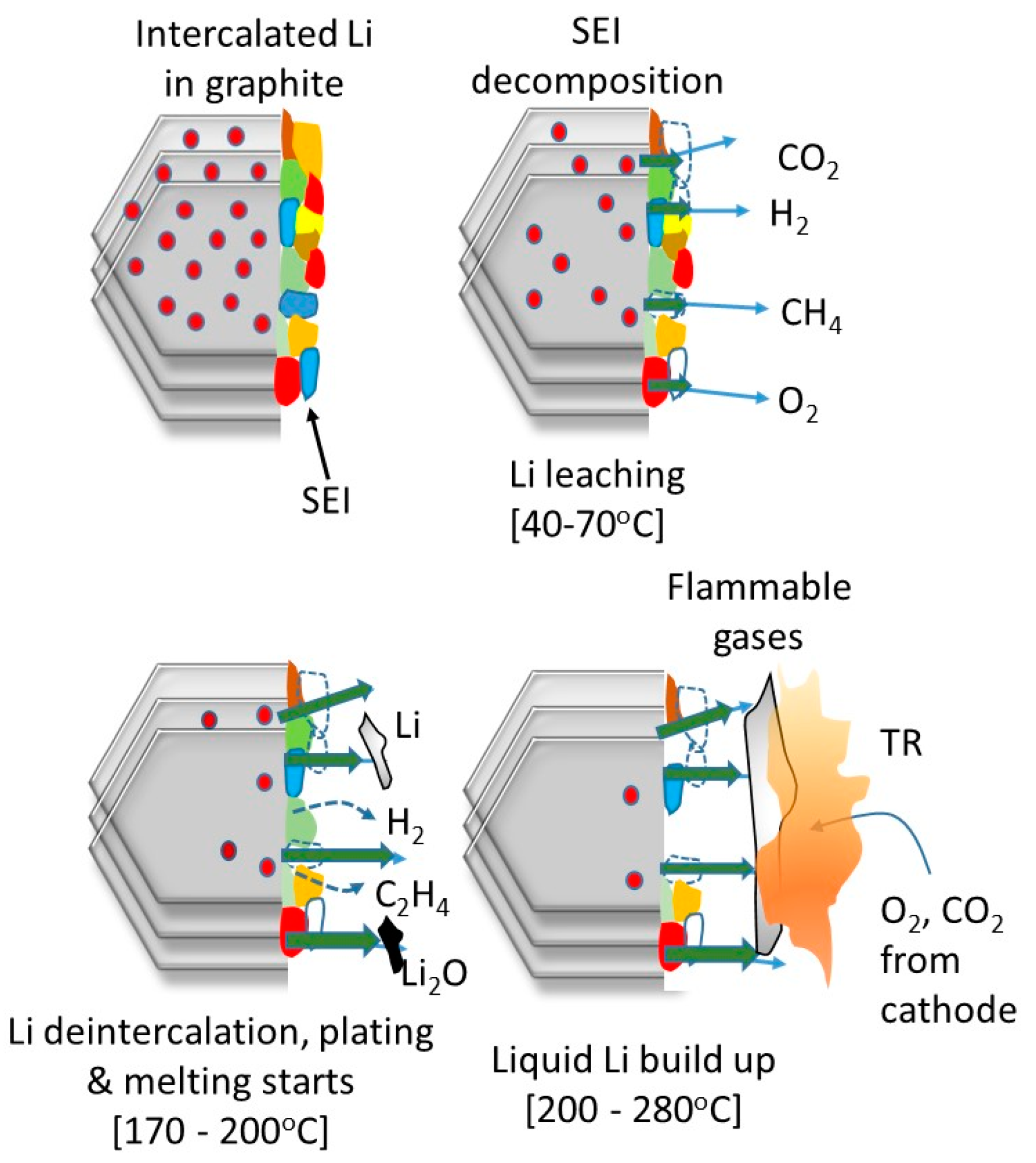
3.2. Triggering Thermal Runaway: High-SOC Regime

Thermal runaway has been commonly identified according to an increase in temperature greater than 2 °C min−1 using accelerated rate calorimetry testing [25]. Alternatively, thermal runaway can be identified according t a cascade of exothermic reactions which lead to high temperatures and subsequent catastrophic cell failure [11]. This event involves a significant amount of damage to the cell.
Both venting and thermal runaway were observed in the high-SOC testing, with heater temperatures of 200 °C and 250 °C required for these thermal events (refer to Table 2). The typical temperatures measured during the high-SOC testing are shown in Figure 3. The temperatures applied uniformly to the cell (via safety testing) were significantly lower than those applied to induce venting and thermal runaway in this work. This is due to the localised nature of heating, whereby heat dissipates from the areas not in contact with the heater. The temperature of the cell will increase where the heat generation exceeds the rate of heat dissipation.
Thermal gradients were observed axially as well as longitudinally on the cell can via selectively placed TCs (refer to Figure 1). The heater TC had the highest temperature until thermal runaway, at which point the TC on the opposite side registered the highest temperature, indicating TR had initiated inside the can. In the 200 °C test, temperatures of up to 650 °C were logged, and in the 250 °C test, temperatures up to 480 °C was logged.
Other studies have shown thermal runaway temperatures on the cell surface of up to 650 °C [28]. Given the violent nature of the reactions involved in thermal runaway and the significant amount of damage observed in the 250 °C cell due to testing, it is likely that the TCs detached from the cell surface, causing lower than expected temperatures.
Studies have shown cell surface temperatures monitored where heating is applied rapidly to the cylindrical cell base using a heat gun [29]. With temperatures > 250 °C, venting and thermal runaway was induced due to localised hotspots. These hotspots were deemed to be caused by severe short circuits, whereby a short-lived release of energy causes thermal runaway. The events that caused this shorting were thought to be dendrite growth, impurities in the cell or internal structural collapse because of contact between highly conductive layers (the current collectors, for example). At a high SOC, cells are more likely to undergo thermal runaway with an internal short circuit (ISC) [30].
Short circuits have been induced (by ISC devices) near to the sidewall and have led to sidewall bursting [31]. These devices provide an electronically conductive path between the negative carbon electrode and the positive aluminium current collector. However, they do not simulate the process of separator melting and shorting via the anode and cathode coming into contact. No sidewall bursts were observed in this study, though this was likely due to the thickness of the cell wall, as discussed below.
A definitive time lag was observed between the venting event and the thermal runaway events, suggesting that additional heat was required to induce TR. To explore the possibility that removing the heat source from the cell would eliminate the resulting TR, the test was repeated at 200 °C with heat removed from the cell once venting had occurred. This is shown in Figure 3d. This had important ramifications in that by removing the heat source (or quenching) following venting, TR can be prevented, provided that self-heating has not started.
Figure 3c shows a distinct drop in temperature just after thermal runaway. This is likely due to the catastrophic nature of thermal runaway causing the thermocouple to be dislodged from this location.
It must be noted that, in our study, localised heat was applied rather than uniform heating to the cell. It is suggested that the temperatures observed in this study are higher than what would be required for self-heating and reactions leading to TR in other experiments.

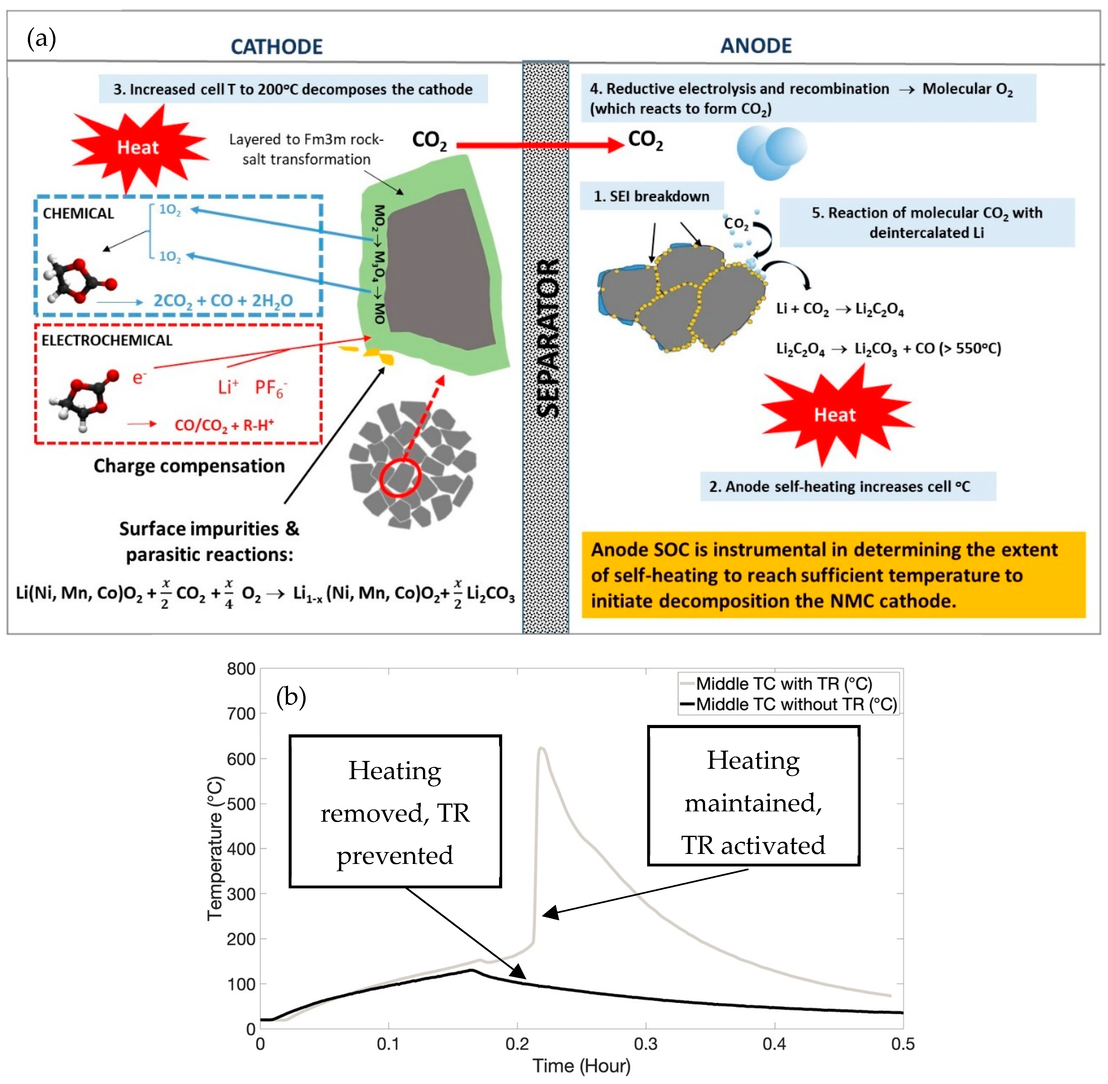
3.3. Implications of the NMC Cathode Chemistry on TR

As previously mentioned, the thermal stability of NMC and the anode’s SOC are instrumental to the severity of TR [14]. In this particular type of LG cylindrical cell, the cathode is NMC532 (Li(Ni0.5Mn0.3Co0.2)O2). When comparing the cathode chemistries, the thermal stability order of different cathode structures has been reported to follow the trend (at full SOC) LFP > LMO > NMC > NCA > LCO, with the latter being the least stable [32].
Within the NMC family of materials, Ni is the most thermally reactive element in terms of the redox dynamics, with Mn being the more redox-stable element. NMC532 is considered to be a good compromise between thermal stability and capacity compared with other members of the NMC series [33]. Charged NMC532 follows a specific path of phase transitions during thermal decomposition:
(i)
LiTMO2 → LiTM2O4 (starting at ca. 235 °C) [33]
(ii)
LiTM2O4→ LiTMO
These transitions are temperature-dependent and correlate with a reduction in O:M stoichiometry due to oxygen loss. Compared with NMC333 and 433, NMC532 has been reported to have better thermal stability, with X-ray diffraction (XRD) and mass spectroscopy (MS) studies demonstrating that the thermal stability dramatically deteriorates when the Ni composition changes from NMC532 to 622 [20,33]. However, such correlations have been questioned based on the comparisons being performed after charging to an equal upper cut-off potential [34,35]. On the basis of analytical verification, the variations in the specific capacity originate from different Li+ extraction ratios, which can predominantly influence the structural stability of layered transition metal oxides [36]. For this reason, the term stability should take into account the structural stability with respect to Li extraction but also thermal stability, which is dependent on the Ni content, electrolyte and SOC. Figure 4 depicts a series of stages known to occur during the initial stages of TR in NMC-graphite cells at high SOCs and can be regarded as co-dependent degradation, linking the anode and cathode. The cascade of reactions begins with the thermal decomposition of the passivating SEI layer on the anode, which can begin at around 90 °C [37]. This is the first stage of the cell’s self-heating behaviour and is followed by further reactions between the electrolyte and intercalated Li (when at a higher SOC), which is an exothermic process and can cause secondary SEI growth [38].
SEI reformation can lead to carbonate species disappearing and inorganic species increasing—such sequences have been referred to as a chain reaction of parasitic exothermic reactions [14]. This will continuously drive the elevation of the cell’s temperature.
At this point, the separator will already have started shrinking, increasing the likelihood of a short circuit (refer to Figure 5a). When the temperature exceeds 200 °C (as is induced in our study), the cathode starts to decompose, accelerating structural decomposition and oxygen release [39]. Localised heating triggers the loss of transition metal (TM) cations by breaking the TM-O bonds, leading to O-O bond formation between the under-coordinated oxygen atoms—this results in parasitic oxygen release [40,41]. In layered oxide materials, the activation energy of oxygen release has been found to be a function of the SOC and the extent of delithiation, as previously mentioned [39]. As the released oxygen causes chemical oxidation of the electrolyte, the amounts of CO2 and CO are generated simultaneously and will increase in volume with an increasing temperature [42]. The adverse effects of CO2 consumption were initially suggested to cause shuttle reactions between the cathodes and anodes, whereby molecular CO2 reacts with deintercalated Li+ to form lithium oxalate (Li2C2O4) [43]. When this species thermally decomposes, the reaction is highly exothermic (<585 °C) [44] and would certainly constitute a dominant self-heating source. However, Girgis [44] also claimed that significant formation of this species was unlikely to occur in commercial cells. In short, there are a variety of chemical cross-talk possibilities between the anode and cathode that culminate in TR, with cathode-released oxygen consumption by the charged anode being a significant stage [14]. Other studies have highlighted that hydrogen is implicated as being one of the critical flammable gas species involved in TR, with its initial release triggered by SEI breakdown and then, at higher temperatures of about 170 °C, by the breakdown of polyvinylidene fluoride (PVdF) [45]. Mechanistic elucidation and quantification of the species formed during TR onset are incredibly complex and still far from being fully resolved and will be considered in separate studies beyond the scope of this investigation. A question that remains is at what point the heat generating the reactions within the cell makes TR inevitable. Previous temperature vs. time plots show a definite time lag between the venting event and the thermal runaway event. This suggests additional (applied) heat is required to induce these internal exothermic reactions after venting so as to induce TR. Figure 5 shows the TR cascade of reactions (a) and the temperature plots of the TR and venting.
As shown in Figure 5b, by removing the heater, we were able to prevent TR, such that the internal heat-generating reactions (such as the cathode decomposition) were not activated. Venting occurred at 0.169 h, after which, if heating was continued, thermal runaway occurred at 0.213 h. Other cooling mechanisms (such as water quenching) could also be applied at this time to further delay TR. The catastrophic nature of TR would be prevented by these actions, thus ensuring safety.

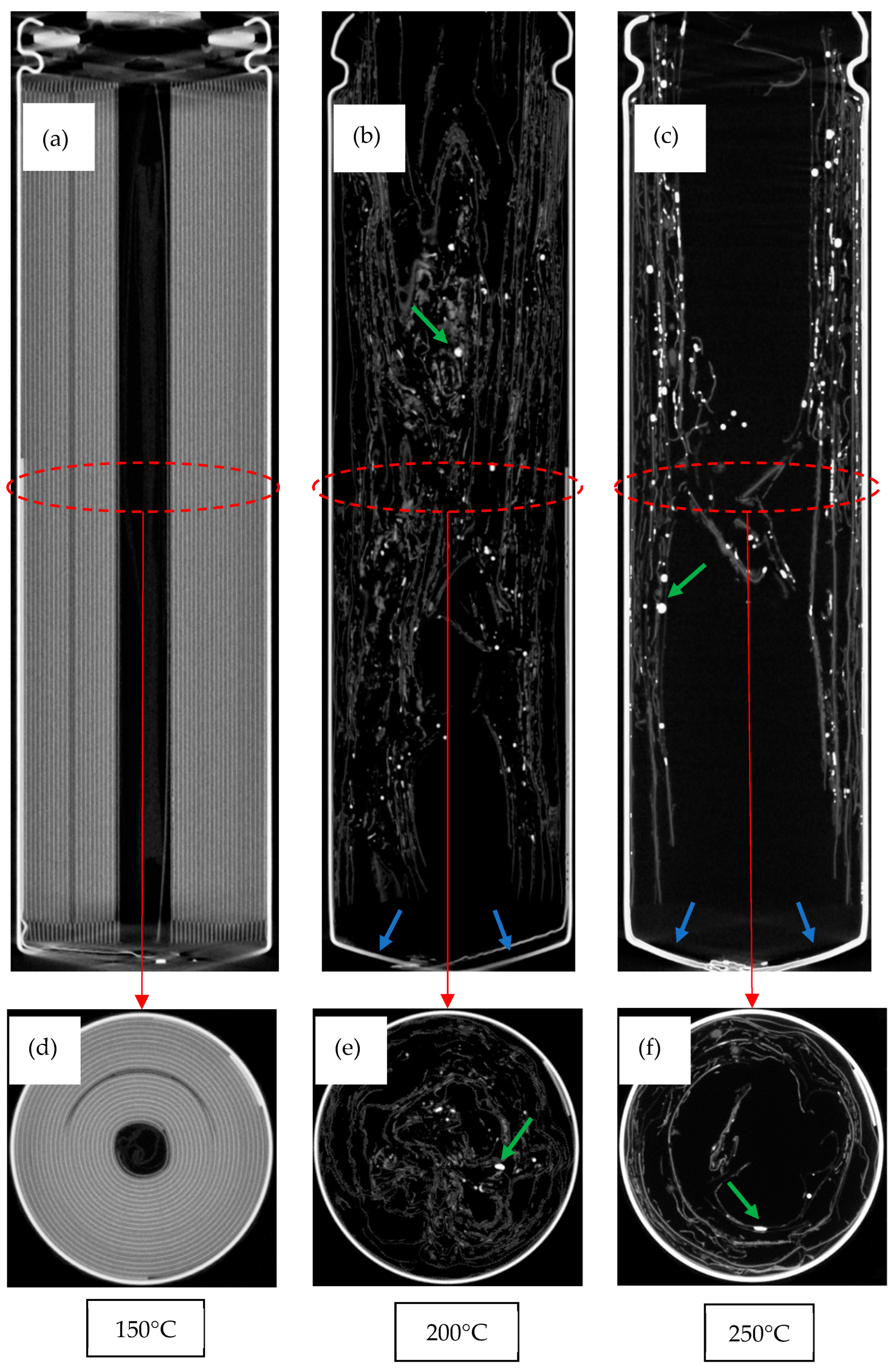
3.4. Examination of the Cells Following Thermal Runaway

The cells that underwent venting and TR in the high-SOC test exhibited significant charring and oxidation, indicators that the cell had ignited and combusted. The combustion process for localised heating to the side of a cylindrical cell has been described previously [26] as continuous heating and self-heating, rupture and ignition, violent ejection or explosion, relatively less violent combustion and flame weakening and extinguishing.
Cells are termed “burst” when the ejection of both the header components and the jelly roll from within the cell components is uncontrolled [28]. Controlled ejection (venting) involves retaining the header components intact, whilst allowing fluids to escape. The cells that had undergone TR experienced the jelly roll componentry exiting through the cell top (refer to Figure 3). In the 250 °C test, the jelly roll extended to four times the length of the cell, which was twice the length of the ejection in the 200 °C cell. This implies that higher applied temperatures caused higher pressures within the cell since the jelly roll exited the cell to a greater length. In other words, higher exposure temperatures induce more pressure, leading to more severe TR.
X-ray tomography has been used extensively to identify the damage induced within cells [4,46]. Extensive damage to the jelly roll is shown in the samples that underwent TR (refer to Figure 6). The gases generated induced a significant amount of stress in the jelly roll layers, causing them to plastically deform and become wave-like. There is a significant amount of void space in the cells, particularly in the 250 °C cell, due to the ejection of the jelly roll through the top of the cell. Bulging was noticed at the cell base in both the 200 °C and 250 °C cells. The aforementioned pressures were high enough to cause plastic deformation (i.e., bulging) of the cell can at this location, though not high enough to rupture the cell wall. More detail on how the pressures cause material stresses within the cell is described below.
The application of heat to one side of the cell did not appear to lead to any anisotropic damage features. The localised heating induced thermal runaway and a pressure increase within the cell until the cell cap was detached and the jelly roll spiralled out of the cell. In a similar study, cells were shown to undergo venting due to the application of a 100 °C temperature [29]. This caused the formation of gas pockets within the jelly roll. Shortly after venting, the jelly roll became severely deformed and collapsed into the void space at the centre of the cell. This collapse led to many “kinks” within the jelly roll, which would likely cause short circuiting due to the damage to the separator.
This collapse of the electrode assembly into the vacant core of the cell has been observed in high-current aging studies [47,48], likely due to the thermal stresses between the (hot) inside and the (cold) outside of the cell, resulting in plastic deformation of the jelly roll layers into the vacant core. The presence of a centre mandrel has been shown to inhibit these jelly roll deformations. It is also believed that having a central mandrel aids in the release of pressure within the cell, as well as making a clear path for fluidised material in venting and thermal runaway [4]. This collapse of the jelly roll into the void space at the centre of the cell is assumed to have occurred here since there was no centre mandrel. It is thought that collapse creates a more tortuous path for the gas evolution within the cell, increasing the risk of cell bursting due to clogging the gas flow at the top of the cell. No sidewall failures occurred in this study, which would likely be one of the effects of this event.
The cell contained both a positive temperature coefficient (PTC) switch and a current interrupt device (CID) at the top (positive) end of the cell. PTC switches are primarily designed to prevent external short circuits, as well as to protect against electrical abuse [49]. This is accomplished by an increase in electrical resistance at elevated temperatures, whereby the current flow to the cell is limited [3]. A CID device is a concave domed disc. In response to pressure build-up within the cell, this disk firstly becomes convex and then ruptures at a certain pressure, initiating the venting process.
TR also stretched the spin groove of the crimp seal such that the crimp angle at the top of the cell was increased. The can at this location was plastically deformed (with the tensile strength of the can exceeded at this location) due to the pressure developed within the cell. The spin groove has been thought to determine the volume of gas that can accumulate in the cell before bursting [4].
As mentioned previously, the temperatures experienced within the cell are believed to be significantly higher than those applied on the outside of the cell. Tomograms show dense materials which are indicated by bright regions, such as the copper current collector. With high applied temperatures, the copper has melted and re-solidified into smaller spheres, which are the highly attenuating globules indicated by the green arrows in Figure 6. The internal temperatures must have reached at least 1085 °C, the melting point of copper. This supports other claims of internal temperatures > 1000 °C during thermal runaway [50].
The mechanical degradation of the cell can after the high-SOC test was evaluated using hardness testing. The testing was carried out on the can at the middle of the heater, with five indents taken at the front and the back of the cell. The hardness values were averaged at these locations and compared for the various temperatures applied in the cell heating test. Figure 7 shows the results of these tests. The thermal profiles solely applied using the heater did not change the mechanical properties of the can. Rather, it was the thermal runaway event that changed its hardness; the can became softer. Hardness testing is directly proportional to the yield strength of a material [51].
The tensile strength of steel has been shown to decrease rapidly at temperatures > 100 °C [28], which would increase the likelihood of the can rupturing. This was not observed here; the tensile strength of the can was maintained in the cells that were exposed to the heating temperatures until the TR event occurred. This softening of the can material was due to exposure to temperatures up to 700 °C. Furthermore, weakening of the casing has been discussed and associated with sidewall rupture [31]. In this study, no sidewall ruptures were observed.
The cell can microstructure changed noticeably as a result of TR. The samples of the as-received cell cans were fabricated from Ni-plated steels with a microstructure comprising cold-worked ferrite grains. These ferrite grains recrystallised and became equiaxed with thermal runaway. In carbon steel, recrystallisation occurs at 721 °C [52], higher temperatures than what those measured using the TCs on the outside of the cell.
The design of the cylindrical cell is analogous to a thin-walled pressure vessel [53]. With some applied internal pressure, the stresses can be resolved into a longitudinal stress (σlong) and a hoop stress (σhoop) acting on the cell ends and radially, respectively (refer to Figure 5b).
This longitudinal stress and hoop stress within the cell can be described using Equations (1) and (2), respectively.
σ l o n g = p D 4 t
σ h o o p = p D 2 t
where σlong = longitudinal stress (MPa), p = internal pressure (MPa), D = internal diameter (mm), t = wall thickness (mm) and σhoop = hoop stress (MPa). As can be seen in the equations, the hoop stress is twice the longitudinal stress. Furthermore, where the cylinder is sufficiently long, the hoop stress is known to be the predominant stress acting upon the cylinder.
A CID device is designed to break in the event of a pressure increase within the cell at a certain (longitudinal) stress, releasing gas into the surroundings. In this way, pressures (and high stresses) that lead to an explosion (and catastrophic failure) can be avoided. Similar engineering controls are adopted in the power industry [54]. Pressure piping is designed to “leak before burst”, which allows time for the detection of leaks from a pipe before it bursts such that the piping can be switched off. Similarly, catastrophic failure is avoided.
Sidewall breaches are known to be one of the worst failure scenarios [28,31] and will occur where the hoop strength of the can has been exceeded by the internal pressure. This scenario was not observed in the testing carried out. This indicates the wall thickness of the can was sufficient to withstand the hoop stresses. Furthermore, with the venting mechanism being designed to be the limiting factor in the event of pressure build-up, this indicates the cell was designed to withstand the correct ratio of longitudinal stress to hoop stress.

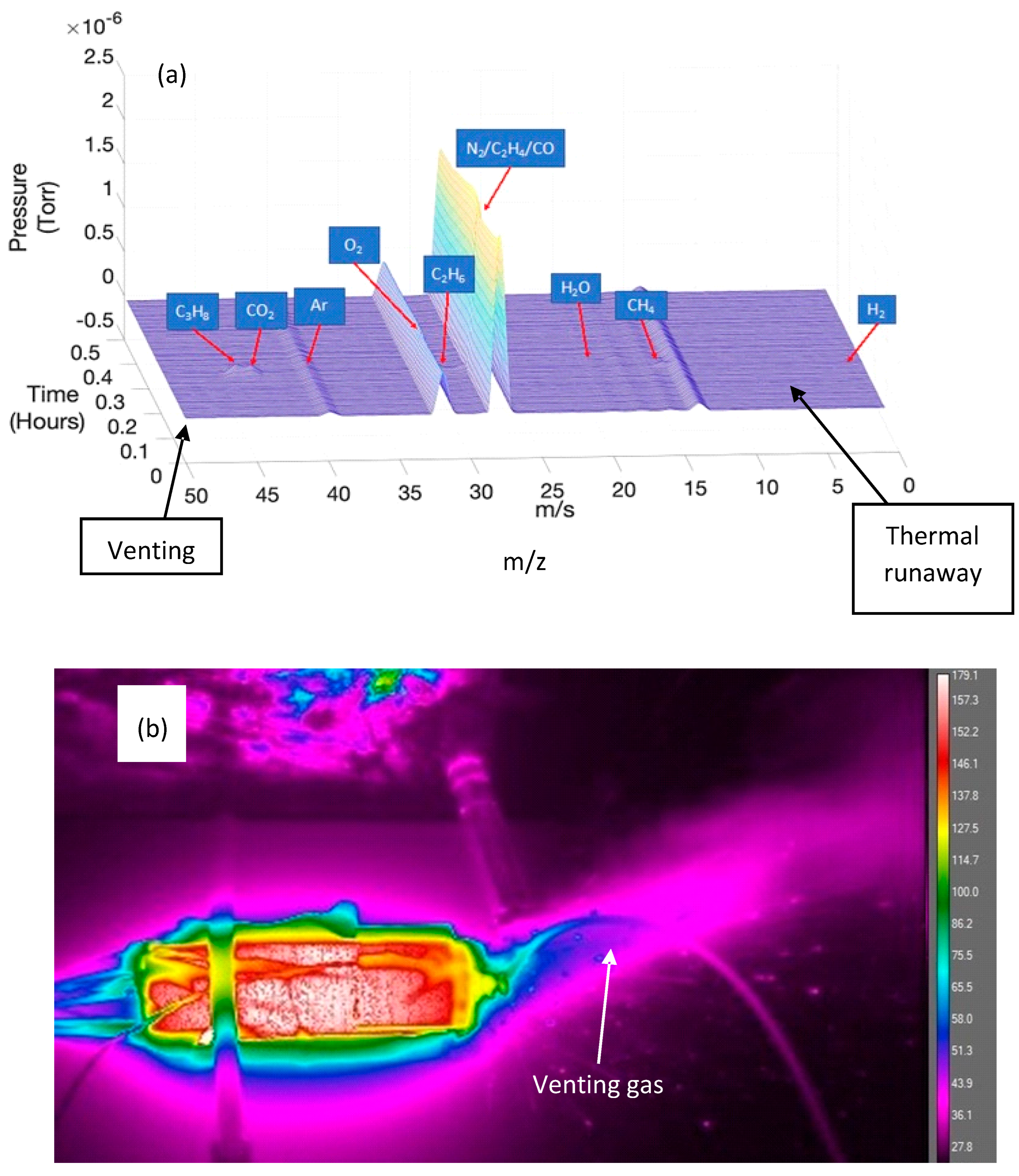
3.5. Released Gas Analysis

Gases were formed by various decomposition reactions inside the cell and released in the venting and TR events. These gases were initially formed by the reactions inside the cell as already mentioned and include the decomposition of several components: the SEI, electrolyte, cathode material, binder and also solvents. Figure 8 shows the typical spectra for the gases observed in the high-SOC test with 200 °C applied. The gases detected during thermal runaway include CH4, C2H4, C2H6, C3H8, H2, H2O, CO, O2 and CO2. Additionally, as the experiment was carried out in an open atmosphere, atmospheric gases (N2, O2, CO2 and Ar) were also detected. Other studies [55] have found many gas species (>100) during thermal runaway due to many reactions occurring at high temperatures. However, this experiment was undertaken in a closed vessel. Since our experiment was carried out in an open atmosphere, with the gas analyser at a distance from the cell top, only qualitative analysis was possible. It is likely that in this situation, only gases at high concentrations were detected (including O2 and N2). Commercial NMC cells were investigated versus other chemistries (LFP, LTO) in a separate study [56], and the NMC cell produced the largest pressure during TR. The major gases analysed here align with the findings in Figure 8a, showing significant peaks of gas species attributable to CO and C2H4.
The gases detected (CO and C2H4) during the venting and TR events were likely to be related to the breakdown of the SEI within the cell and the related cathode shuttle mechanisms, as outlined in Figure 5.

4. Conclusions

In this study, we have focused on the significant interplay between the cell SOC and temperature towards the nature of thermal failure in lithium-ion cells. By simulating a realistic thermal scenario and applying an external temperature to the outside of the cell, we monitored the cell until it reached eventual TR. It is already known from other studies that the decomposition of the anode is the critical driver for TR onset via a self-heating mode, which drives the decomposition of the cathode via a series of “shuttle” stages. At a high SOC, whereby the graphite is lithiated, this will increase the rate of self-heating. By allowing continued exothermic anode decomposition, catastrophic failure will result. We demonstrate that by implementing a simple convection cooling mechanism—removing the heat source—we could suppress TR.
This practical solution warrants the investigation of other quenching methods that can be activated when the temperature exceeds a critical threshold. Such studies serve to better inform improving the development of thermal management systems: for example, a better distribution of effective refrigerants or the use of improved heat-dissipating materials. Vital to activating such mechanisms will be continued advancements in temperature sensing capable of fast detection and precise measurement. Underpinning such technology developments with forensic simulations is an effective approach to resolving when and how to implement better safety controls. This will ultimately serve to mitigate catastrophic failure in cells and modules and will become more critical as we continue to increase the cell format sizes and use higher-energy-density electrodes.

Author Contributions

J.H.: conceptualisation, methodology, validation, investigation, resources, writing—original draft, supervision, project administration, funding acquisition. M.M.: software, formal analysis, investigation, writing—original draft, writing—review and editing. I.H.: investigation. G.R.: investigation. L.P.: writing—review and editing, visualisation. M.A.W.: writing—reviewing and editing, M.J.L.: writing—review and editing, visualisation. All authors have read and agreed to the published version of the manuscript.

Funding

This research received no external funding.

Data Availability Statement

The data presented in this study are available on request from the corresponding author. The data are not publicly available due to confidentiality.

Acknowledgments

The research was undertaken in collaboration with the WMG Centre’s High Value Manufacturing Catapult (funded by Innovate UK). We acknowledge the Faraday Institution’s Degradation and SafeBatt projects, grant references RG94392 FRIG024 and FIRG061. The authors would also like to acknowledge the National Research Facility for X-ray Computed Tomography (NXCT), grant reference EP/T02593X/1.

Conflicts of Interest

There are no conflicts of interest in this manuscript.

Glossary

CCconstant current
CVconstant voltage
Ccoulomb
NMClithium nickel cobalt manganese oxide
SEIsolid electrolyte interphase
SOCstate of charge
TRthermal runaway
LIBlithium-ion battery
BMSbattery management system
TCthermocouple
PIDproportional integral derivative controller
CIDcurrent interrupt device
PTCpositive temperature coefficient device
QMSquadrupole mass spectrometer
PCBprinted circuit board
ISCinternal short circuit
XRDX-ray diffraction
MSmass spectroscopy
TMtransition metal
PVdFpolyvinylidene fluoride
NDTnon-destructive testing

References

  1. Koch, S.; Fill, A.; Birke, K.P. Comprehensive gas analysis on large scale automotive lithium-ion cells in thermal runaway. J. Power Sources 2018, 398, 106–112. [Google Scholar] [CrossRef]
  2. Xu, K. Nonaqueous liquid electrolytes for lithium-based rechargeable batteries. Chem. Rev. 2004, 104, 4303–4417. [Google Scholar] [CrossRef]
  3. Lisbona, D.; Snee, T. A review of hazards associated with primary lithium and lithium-ion batteries. Process Saf. Environ. Prot. 2011, 89, 434–442. [Google Scholar] [CrossRef]
  4. Finegan, D.P.; Darcy, E.; Keyser, M.; Tjaden, B.; Heenan, T.M.M.; Jervis, R.; Bailey, J.J.; Vo, N.T.; Magdysyuk, O.V.; Drakopoulos, M.; et al. Identifying the Cause of Rupture of Li-Ion Batteries during Thermal Runaway. Adv. Sci. 2018, 5, 1700369. [Google Scholar] [CrossRef]
  5. Hou, J.; Lu, L.; Wang, L.; Ohma, A.; Ren, D.; Feng, X.; Li, Y.; Li, Y.; Ootani, I.; Han, X.; et al. Thermal runaway of Lithium-ion batteries employing LiN(SO2F)2-based concentrated electrolytes. Nat. Commun. 2020, 11, 5100. [Google Scholar] [CrossRef]
  6. Cai, T.; Valecha, P.; Tran, V.; Engle, B.; Stefanopoulou, A.; Siegel, J. Detection of Li-ion battery failure and venting with Carbon Dioxide sensors. eTransportation 2021, 7, 100100. [Google Scholar] [CrossRef]
  7. Gao, A.; Xu, F.; Dong, W. The Concept of early monitoring and warning of thermal runaway of lithium-ion power battery using parameter analysis. J. Phys. Conf. Ser. 2022, 2181, 012020. [Google Scholar] [CrossRef]
  8. McKerracher, R.D.; Guzman-Guemez, J.; Wills, R.G.A.; Sharkh, S.M.; Kramer, D. Advances in Prevention of Thermal Runaway in Lithium-Ion Batteries. Adv. Energy Sustain. Res. 2021, 2, 2000059. [Google Scholar] [CrossRef]
  9. Srinivasan, R.; Demirev, P.A.; Carkhuff, B.G.; Santhanagopalan, S.; Jeevarajan, J.A.; Barrera, T.P. Review—Thermal Safety Management in Li-Ion Batteries: Current Issues and Perspectives. J. Electrochem. Soc. 2020, 167, 140516. [Google Scholar] [CrossRef]
  10. Golubkov, A.W.; Fuchs, D.; Wagner, J.; Wiltsche, H.; Stangl, C.; Fauler, G.; Voitic, G.; Thaler, A.; Hacker, V. Thermal-runaway experiments on consumer Li-ion batteries with metal-oxide and olivin-type cathodes. RSC Adv. 2014, 4, 3633–3642. [Google Scholar] [CrossRef]
  11. Spotnitz, R.; Franklin, J. Abuse behavior of high-power, lithium-ion cells. J. Power Sources 2003, 113, 81–100. [Google Scholar] [CrossRef]
  12. UL 2054; Household and Commercial Batteries. Underwriters Laboratories Inc.: Chicago, IL, USA, 2005.
  13. Bareño, J.; Dietz Rago, N.; Dogan, F.; Graczyk, D.G.; Tsai, Y.; Naik, S.R.; Han, S.D.; Lee, E.; Du, Z.; Sheng, Y.; et al. Effect of overcharge on Li(Ni0.5Mn0.3Co0.2)O2/graphite lithium ion cells with poly(vinylidene fluoride) binder. III—Chemical changes in the cathode. J. Power Sources 2018, 385, 165–171. [Google Scholar] [CrossRef]
  14. Liu, X.; Ren, D.; Hsu, H.; Feng, X.; Xu, G.L.; Zhuang, M.; Gao, H.; Lu, L.; Han, X.; Chu, Z.; et al. Thermal Runaway of Lithium-Ion Batteries without Internal Short Circuit. Joule 2018, 2, 2047–2064. [Google Scholar] [CrossRef]
  15. Mendoza-Hernandez, O.S.; Ishikawa, H.; Nishikawa, Y.; Maruyama, Y.; Umeda, M. Cathode material comparison of thermal runaway behavior of Li-ion cells at different state of charges including over charge. J. Power Sources 2015, 280, 499–504. [Google Scholar] [CrossRef]
  16. Gilbert, J.A.; Bareño, J.; Spila, T.; Trask, S.E.; Miller, D.J.; Polzin, B.J.; Jansen, A.N.; Abraham, D.P. Cycling Behavior of NCM523/Graphite Lithium-Ion Cells in the 3–4.4 V Range: Diagnostic Studies of Full Cells and Harvested Electrodes. J. Electrochem. Soc. 2017, 164, A6054–A6065. [Google Scholar] [CrossRef]
  17. Wu, L.; Nam, K.W.; Wang, X.; Zhou, Y.; Zheng, J.C.; Yang, X.Q.; Zhu, Y. Structural origin of overcharge-induced thermal instability of Ni-containing layered-cathodes for high-energy-density lithium batteries. Chem. Mater. 2011, 23, 3953–3960. [Google Scholar] [CrossRef]
  18. Shu, J.; Ma, R.; Shao, L.; Shui, M.; Wu, K.; Lao, M.; Wang, D.; Long, N.; Ren, Y. In-situ X-ray diffraction study on the structural evolutions of LiNi 0.5Co0.3Mn0.2O2 in different working potential windows. J. Power Sources 2014, 245, 7–18. [Google Scholar] [CrossRef]
  19. Zheng, Y.; Qian, K.; Luo, D.; Li, Y.; Lu, Q.; Li, B.; He, Y.B.; Wang, X.; Li, J.; Kang, F. Influence of over-discharge on the lifetime and performance of LiFePO4/graphite batteries. RSC Adv. 2016, 6, 30474–30483. [Google Scholar] [CrossRef]
  20. Li, T.; Yuan, X.-Z.; Zhang, L.; Song, D.; Shi, K.; Bock, C. Degradation Mechanisms and Mitigation Strategies of Nickel-Rich NMC-Based Lithium-Ion Batteries; Electrochemical Energy Reviews; Springer: Singapore, 2020; Volume 3. [Google Scholar]
  21. Zeng, X.; Zhan, C.; Lu, J.; Amine, K. Stabilization of a High-Capacity and High-Power Nickel-Based Cathode for Li-Ion Batteries. Chem 2018, 4, 690–704. [Google Scholar] [CrossRef]
  22. Shizuka, K.; Kiyohara, C.; Shima, K.; Takeda, Y. Effect of CO2 on layered Li1+zNi1−x−yCoxMyO2 (M = Al, Mn) cathode materials for lithium ion batteries. J. Power Sources 2007, 166, 233–238. [Google Scholar] [CrossRef]
  23. Wang, D.; Zheng, L.; Li, X.; Du, G.; Feng, Y.; Jia, L.; Dai, Z. Effect of high Ni on battery thermal safety. Int. J. Energy Res. 2020, 44, 12158–12168. [Google Scholar] [CrossRef]
  24. Tan, C.C.; Walker, M.; Remy, G.; Kourra, N.; Maddar, F.; Dixon, S.; Williams, M.; Loveridge, M.J. Ageing analysis and asymmetric stress considerations for small format cylindrical cells for wearable electronic devices. J. Power Sources 2020, 472, 228626. [Google Scholar] [CrossRef]
  25. Lammer, M.; Königseder, A.; Hacker, V. Holistic methodology for characterisation of the thermally induced failure of commercially available 18650 lithium ion cells. RSC Adv. 2017, 7, 24425–24429. [Google Scholar] [CrossRef]
  26. Chen, M.; Liu, J.; He, Y.; Yuen, R.; Wang, J. Study of the fire hazards of lithium-ion batteries at different pressures. Appl. Therm. Eng. 2017, 125, 1061–1074. [Google Scholar] [CrossRef]
  27. Somandepalli, V.; Marr, K.; Horn, Q. Quantification of combustion hazards of thermal runaway failures in lithium-ion batteries. SAE Int. J. Altern. Powertrains 2014, 3, 98–104. [Google Scholar] [CrossRef]
  28. Finegan, D.P.; Darst, J.; Walker, W.; Li, Q.; Yang, C.; Jervis, R.; Heenan, T.M.M.; Hack, J.; Thomas, J.C.; Rack, A.; et al. Modelling and experiments to identify high-risk failure scenarios for testing the safety of lithium-ion cells. J. Power Sources 2019, 417, 29–41. [Google Scholar] [CrossRef]
  29. Finegan, D.P.; Scheel, M.; Robinson, J.B.; Tjaden, B.; Hunt, I.; Mason, T.J.; Millichamp, J.; Di Michiel, M.; Offer, G.J.; Hinds, G.; et al. In-operando high-speed tomography of lithium-ion batteries during thermal runaway. Nat. Commun. 2015, 6, 6924. [Google Scholar] [CrossRef]
  30. Doughty, D.; Roth, E.P. A general discussion of Li Ion battery safety. Electrochem. Soc. Interface 2012, 21, 37–44. [Google Scholar]
  31. Finegan, D.P.; Darcy, E.; Keyser, M.; Tjaden, B.; Heenan, T.M.M.; Jervis, R.; Bailey, J.J.; Malik, R.; Vo, N.T.; Magdysyuk, O.V.; et al. Characterising thermal runaway within lithium-ion cells by inducing and monitoring internal short circuits. Energy Environ. Sci. 2017, 10, 1377–1388. [Google Scholar] [CrossRef]
  32. Furushima, Y.; Yanagisawa, C.; Nakagawa, T.; Aoki, Y.; Muraki, N. Thermal stability and kinetics of delithiated LiCoO2. J. Power Sources 2011, 196, 2260–2263. [Google Scholar] [CrossRef]
  33. Bak, S.; Hu, E.; Zhou, Y.; Yu, X.; Senanayake, S.D.; Cho, S.; Kim, K.; Chung, K.Y.; Yang, X.; Nam, K. Structural Changes and Thermal Stability of Charged LiNi. Appl. Mater. Interfaces 2014, 6, 22594–22601. [Google Scholar] [CrossRef] [PubMed]
  34. Kasnatscheew, J.; Evertz, M.; Streipert, B.; Wagner, R.; Klöpsch, R.; Vortmann, B.; Hahn, H.; Nowak, S.; Amereller, M.; Gentschev, A.C.; et al. The truth about the 1st cycle Coulombic efficiency of LiNi1/3Co1/3Mn1/3O2 (NCM) cathodes. Phys. Chem. Chem. Phys. 2016, 18, 3956–3965. [Google Scholar] [CrossRef] [PubMed]
  35. Shi, Y.; Chen, G.; Liu, F.; Yue, X.; Chen, Z. Resolving the Compositional and Structural Defects of Degraded LiNixCoyMnzO2 Particles to Directly Regenerate High-Performance Lithium-Ion Battery Cathodes. ACS Energy Lett. 2018, 3, 1683–1692. [Google Scholar] [CrossRef]
  36. Kasnatscheew, J.; Röser, S.; Börner, M.; Winter, M. Do Increased Ni Contents in LiNixMnyCozO2 (NMC) Electrodes Decrease Structural and Thermal Stability of Li Ion Batteries? A Thorough Look by Consideration of the Li+ Extraction Ratio. ACS Appl. Energy Mater. 2019, 2, 7733–7737. [Google Scholar] [CrossRef]
  37. Adams, R.A.; Varma, A.; Pol, V.G. Mechanistic elucidation of thermal runaway in potassium-ion batteries. J. Power Sources 2018, 375, 131–137. [Google Scholar] [CrossRef]
  38. Mao, B.; Huang, P.; Chen, H.; Wang, Q.; Sun, J. Self-heating reaction and thermal runaway criticality of the lithium ion battery. Int. J. Heat Mass Transf. 2020, 149, 119178. [Google Scholar] [CrossRef]
  39. Sharifi-Asl, S.; Lu, J.; Amine, K.; Shahbazian-Yassar, R. Oxygen Release Degradation in Li-Ion Battery Cathode Materials: Mechanisms and Mitigating Approaches. Adv. Energy Mater. 2019, 9, 1900551. [Google Scholar] [CrossRef]
  40. Yano, A.; Shikano, M.; Ueda, A.; Sakaebe, H.; Ogumi, Z. LiCoO2 Degradation Behavior in the High-Voltage Phase Transition Region and Improved Reversibility with Surface Coating. J. Electrochem. Soc. 2017, 164, A6116–A6122. [Google Scholar] [CrossRef]
  41. Nam, K.-W.; Bak, S.-M.; Hu, E.; Yu, X.; Zhou, Y.; Wang, X.; Wu, L.; Zhu, Y.; Chung, K.-Y.; Yang, X.-Q. Combining In Situ Synchrotron X-Ray Diffraction and Absorption Techniques with Transmission Electron Microscopy to Study the Origin of Thermal Instability in Overcharged Cathode Materials for Lithium-Ion Batteries. Adv. Func. Mater. 2013, 23, 1047–1063. [Google Scholar] [CrossRef]
  42. Jung, R.; Strobl, P.; Maglia, F.; Stinner, C.; Gasteiger, H.A. Temperature Dependence of Oxygen Release from LiNi0.6Mn0.2Co0.2O2 (NMC622) Cathode Materials for Li-Ion Batteries. J. Electrochem. Soc. 2018, 165, A2869–A2879. [Google Scholar] [CrossRef]
  43. Ellis, L.D.; Allen, J.P.; Thompson, L.M.; Harlow, J.E.; Stone, W.J.; Hill, I.G.; Dahn, J.R. Quantifying, Understanding and Evaluating the Effects of Gas Consumption in Lithium-Ion Cells. J. Electrochem. Soc. 2017, 164, A3518–A3528. [Google Scholar] [CrossRef]
  44. Girgis, M.M.; El-Awad, A.M. Kinetics and mechanism of thermal decomposition of lithium oxalate catalysed by Cd1−xCoxFe2O4(x = 0.0, 0.5 and 1.0) ferrospinel additives. Thermochim. Acta 1993, 214, 291–303. [Google Scholar] [CrossRef]
  45. Liu, X.; Yin, L.; Ren, D.; Wang, L.; Ren, Y.; Xu, W.; Lapidus, S.; Wang, H.; He, X.; Chen, Z.; et al. In situ observation of thermal-driven degradation and safety concerns of lithiated graphite anode. Nat. Commun. 2021, 12, 4235. [Google Scholar] [CrossRef] [PubMed]
  46. Yufit, V.; Shearing, P.; Hamilton, R.W.; Lee, P.D.; Wu, M.; Brandon, N.P. Investigation of lithium-ion polymer battery cell failure using X-ray computed tomography. Electrochem. Commun. 2011, 13, 608–610. [Google Scholar] [CrossRef]
  47. Holloway, J.; Maddar, F.; Lain, M.; Loveridge, M.; Copley, M.; Kendrick, E.; Greenwood, D. Determining the limits and effects of high-rate cycling on lithium iron phosphate cylindrical cells. Batteries 2020, 6, 57. [Google Scholar] [CrossRef]
  48. Fleischhammer, M.; Waldmann, T.; Bisle, G.; Hogg, B.I.; Wohlfahrt-Mehrens, M. Interaction of cyclic ageing at high-rate and low temperatures and safety in lithium-ion batteries. J. Power Sources 2015, 274, 432–439. [Google Scholar] [CrossRef]
  49. Balakrishnan, P.G.; Ramesh, R.; Prem Kumar, T. Safety mechanisms in lithium-ion batteries. J. Power Sources 2006, 155, 401–414. [Google Scholar] [CrossRef]
  50. Golubkov, A.W.; Scheikl, S.; Planteu, R.; Voitic, G.; Wiltsche, H.; Stangl, C.; Fauler, G.; Thaler, A.; Hacker, V. Thermal runaway of commercial 18650 Li-ion batteries with LFP and NCA cathodes—Impact of state of charge and overcharge. RSC Adv. 2015, 5, 57171–57186. [Google Scholar] [CrossRef]
  51. Jun, S.C. Graphene-Based Energy Devices; Mechanical Testing and Evaluation; Wiley-VCH Verlag GmbH & Co.: Weinheim, Germany, 2015. [Google Scholar]
  52. Baker, H. Alloy Phase Diagrams. In ASM Handbook; ASM International: Cleveland, OH, USA, 1992; Volume 3. [Google Scholar]
  53. Becker, W. Failure Analysis and Prevention. In ASM Handbook; ASM International: Materials Park, OH, USA, 2002; Volume 11. [Google Scholar]
  54. Cartwright, R. Book Reviews: Book Reviews. Perspect. Public Health 2010, 130, 239. [Google Scholar] [CrossRef]
  55. Sun, J.; Li, J.; Zhou, T.; Yang, K.; Wei, S.; Tang, N.; Dang, N.; Li, H.; Qiu, X.; Chen, L. Toxicity, a serious concern of thermal runaway from commercial Li-ion battery. Nano Energy 2016, 27, 313–319. [Google Scholar] [CrossRef]
  56. Yuan, L.; Dubaniewicz, T.; Zlochower, I.; Thomas, R.; Rayyan, N. Experimental study on thermal runaway and vented gases of lithium-ion cells. Process Saf. Environ. Prot. 2020, 144, 186–192. [Google Scholar] [CrossRef]
Figure 1. Images of (a) a real field failure situation, (b) 4xperimental setup to emulate the failure situation and (c) location of TCs on an individual cell.
Batteries 10 00104 g001
Figure 2. Temperature plots and images after testing for low-SOC test. Typical plots and images are shown after the test for 150 °C (a), 200 °C (b) and 250 °C (c).
Batteries 10 00104 g002
Figure 3. Temperature plots and images after testing for high-SOC test, for (a) 150 °C, (b), 200 °C and (c) 250 °C. (d) shows a typical plot at 200 °C when heating was removed after venting, preventing TR.
Batteries 10 00104 g003
Figure 4. Implication of high SOC in anode on the onset events leading to TR.
Batteries 10 00104 g004
Figure 5. (a) Decomposition cascade highlighting co-dependent behaviours of anodes and cathodes during cell heating; (b) temperature plots for cells with high SOC and 200 °C with and without TR activation.
Batteries 10 00104 g005
Figure 6. Tomograms of cells after testing. Longitudinal scans shown in (ac). Axial scans shown in (df). Blue arrows show bulging, and green arrows show examples of melted copper.
Batteries 10 00104 g006
Figure 7. Mechanical degradation and design of cylindrical cells. (a) shows average mechanical properties of the cell can, (b) shows mechanical design and associated stresses and (c) shows typical microstructure.
Batteries 10 00104 g007
Figure 8. Results from gas analysis. (a) shows GC–MS spectra for high-SOC test at 200 °C, and (b) shows thermographic image taken during venting.
Batteries 10 00104 g008
Table 1. Summary of testing results for low SOC regime.
TestTemperature (°C)Events
Low-SOC100Nil
150Nil
200Venting only
250Venting only
Table 2. Summary of testing results for high SOC regime.
TestTemperature (°C)Events
High SOC100Nil
150Nil
200Venting and TR
250Venting and TR
Disclaimer/Publisher’s Note: The statements, opinions and data contained in all publications are solely those of the individual author(s) and contributor(s) and not of MDPI and/or the editor(s). MDPI and/or the editor(s) disclaim responsibility for any injury to people or property resulting from any ideas, methods, instructions or products referred to in the content.

