1. Introduction
The parafoil is controllable. Compared with the traditional circular parachute airdrop system, the airdrop system composed of the parafoil can achieve a precise airdrop of fixed-point targets under the controller’s action. The parafoil airdrop system has a wide range of application values, such as the airdrop of relief materials in a disaster environment, the efficient delivery of military materials, such as weapons and ammunition in combat areas, and the accurate recovery of spacecraft [
1]. For example, in June 2021, China successfully recovered the Chang San Yi rocket booster through its recovery system. Similar to other unmanned aerial vehicles, the parafoil airdrop system also needs to track the planned trajectory when it realizes the autonomous homing operation [
2,
3,
4,
5]. Therefore, scientifically planning a high-quality homing trajectory is the premise for the parafoil airdrop system to achieve reliable autonomous flight. It is also an essential guarantee for the final realization of an accurate and safe airdrop [
6,
7,
8,
9].
The parafoil airdrop system is a soft-wing system, and its flight is easily disturbed by the surrounding environment, such as terrain and wind [
10]. It is a nonlinear system and has many restrictions on its control. Therefore, various conditions and constraints must be considered for its homing trajectory planning [
11,
12,
13]. The research on the autonomous homing trajectory of the parafoil airdrop system mainly focused on two aspects. On the one hand, the homing trajectory was designed based on optimal control, which is a method to obtain the optimal control law under the designed objective function and various given constraints. For example, based on the parafoil point-mass model, Refs. [
14,
15,
16] established a combined objective function, which considers the shortest landing distance, headwind landing, and energy-saving conditions. Under the constraints of airdrop starting point, target point, and control quantity, the objective function was solved by the Gaussian pseudo-spectral method, or improved genetic algorithm, to obtain the optimal trajectory. In Refs. [
17,
18], the design method of the optimal trajectory under abnormal conditions, namely, insufficient launch height of the parafoil airdrop system and the failure of the actuator of the control system during the homing process, was studied. The objective function and constraints were obtained, and the Gauss pseudo-spectral method received the control rate. Based on the point-mass model in the wind field environment, Luo et al. [
19] studied the planning of the homing trajectory in complex areas, such as multi-peak landforms, established an obstacle model, designed an objective function for multi-objective combined optimization, and obtained the optimal homing trajectory and control rate under given constraints. Considering an error between the traditional point-mass model in trajectory planning and the actual flight situation, Sun et al. [
20,
21,
22] proposed a third-order trajectory optimization strategy based on the six-degree-of-freedom model.
From the above research, it is not difficult to see that the use of optimal control theory to solve the homing trajectory planning problem of the parafoil system achieved rich results, which are similar to the problems of traditional aircraft, including the application and improvement of optimal algorithm, homing environment, and condition limitation. It promotes the research depth of parafoil homing trajectory. However, the parafoil airdrop system does not usually have a power propulsion device, so it cannot fly freely like traditional aircraft, and the amount of control needs to be kept within a small range to ensure the safe flight of the system. Trajectories designed by optimal theory frequently operate on control quantities, especially in complex environments, and are difficult to use in practical engineering applications.
On the other hand, the trajectory planning of the parafoil airdrop system was segmentally planned. According to the unique flight characteristics of the parafoil system, the trajectory design was planned and implemented step by step from the initial release point to the target point according to specific rules, taking into account the design process. In the trajectory design process, performance indicators, such as energy consumption, stability, and safety, were taken into account to make the planned trajectory as optimal as possible. In Ref. [
23], the target point was set in the center of the hovering height elimination area, and the homing trajectory of the parafoil system was designed in sections. The optimal solution of the objective function was solved through the AP-QDEA optimization algorithm proposed in the paper to determine the homing trajectory of each section. Ref. [
24] studied the segmental design of the homing trajectory of the parafoil system in the risk and obstacle avoidance environment and combined it with the optimal trajectory planning theory. A hybrid trajectory planning method was proposed to obtain the trajectory segments under different conditions. However, in the currently more common segmented trajectory design scheme, the target point was usually designed at the center point of the hovering area, which meant the length of the upwind gliding flight segment was limited by the length of the radius of the hovering area when the airdrop system was landing and brought challenges to the accuracy and safety of landing.
The control rate of the parafoil airdrop system obtained according to the optimal control theory usually has frequent cross control of the left and right parafoil ropes when realized, increasing the difficulty in engineering practice. The segmented trajectory considers the characteristics of the parafoil at the beginning of the trajectory design, which has the advantage of being designed in advance. At the same time, the trajectory designed by this method is easier to realize in the actual tracking overcharge. Aiming at the shortcomings of the existing segmented flight trajectory, this paper improves the segmented method of the trajectory and proposes a new segmented flight trajectory design scheme, which provides a new reference for the autonomous homing flight of the parafoil airdrop system. The main contributions of this paper are as follows:
Based on the geometric segmentation strategy, a new autonomous homing scheme for the parafoil airdrop system was designed. The straight-line flight segment before landing was designed on the tangent of the circle with reduced height, and its length can be freely controlled. Compared with the target point being developed at the center of the circle with reduced altitude, it avoids the problem that the length of the straight flight segment before landing is subject to the circling radius and provides a guarantee for the smooth implementation of a bird landing, in terms of landing accuracy and safety;
The objective function of trajectory optimization is established, and the calculation method and constraints of trajectory parameters are introduced in detail. The realization process of the new method of trajectory planning is described with examples;
Different initial conditions for airdrops are set. The trajectory planned by the new scheme was simulated and verified, and a comparative analysis and discussion with the traditional scheme are carried out, which proves the effectiveness of the trajectory planning scheme designed in this paper.
2. Materials and Methods
2.1. Construction of Point-Mass Model of Airdrop System
The parafoil autonomous airdrop system generally consists of the parafoil, the load-carrying object, the object to be airdropped, and the controller [
25,
26]. The parafoil airdrop system with an autonomous homing function does not have a power device. Its homing is realized by controlling the left and right pull-down parafoil ropes at the rear edge of the parafoil during its descent. The controller controls the servo mechanism that performs the pull-down action of the parafoil rope. When the parachute rope’s pull-down amplitude on the parafoil’s left side is more significant than that on the right side, the airdrop system performs a left turn flight. Instead, the airdrop system performs a right-turn flight. The airdrop system performs gliding flight when the left and right pulling amplitudes are equal. Through reasonable flight control by the controller, the parafoil airdrop system can achieve autonomous flight and airdrop materials to the designated destination.
Without external interference, the airdrop system drops steadily under the action of gravity and aerodynamic force. In order to ensure overall stability and safety, the moment of inertia is ignored, and the pull-down amplitude of one side of the parafoil rope must be kept within a small range. Therefore, the following settings are made in this paper:
Based on the geodetic coordinate system, the point-mass motion equation of parafoil airdrop system is established, as shown in Equation (1), which is used for trajectory planning in the homing process of the system:
In Equation (1),
is the position of the system,
is the control quantity,
is the turning angle, and
is the transverse wind speed of the space where the system is located. The wind is usually greatly affected by the airdrop environment, and the parafoil airdrop system has relatively high requirements for the airdrop environment. Therefore, generally, only the impact of the average wind field on the parafoil flight is considered. For the convenience of research, the impact of the average wind field is usually converted into the trajectory tracking error, and only the effect of the wind direction is considered. This paper also follows this treatment method. That is
. The point-mass model of can be further simplified, as shown in Equation (2):
2.2. Design of Homing Trajectory
The parafoil airdrop system itself does not have a power device. By controlling the two pull-down parachute ropes on the left and right of the trailing edge, the parafoil can home autonomously. The entire segmented homing process can generally be divided into three parts: centripetal, energy control, and landing, as shown in
Figure 1.
Centripetal flight is used to reduce the distance difference between the airdrop system and the target point. Capability control flight is used to eliminate the high degree of redundancy existing in the airdrop system. Landing flight is mainly used to adjust the flight direction, which is prepared for the windward landing of the airdrop system.
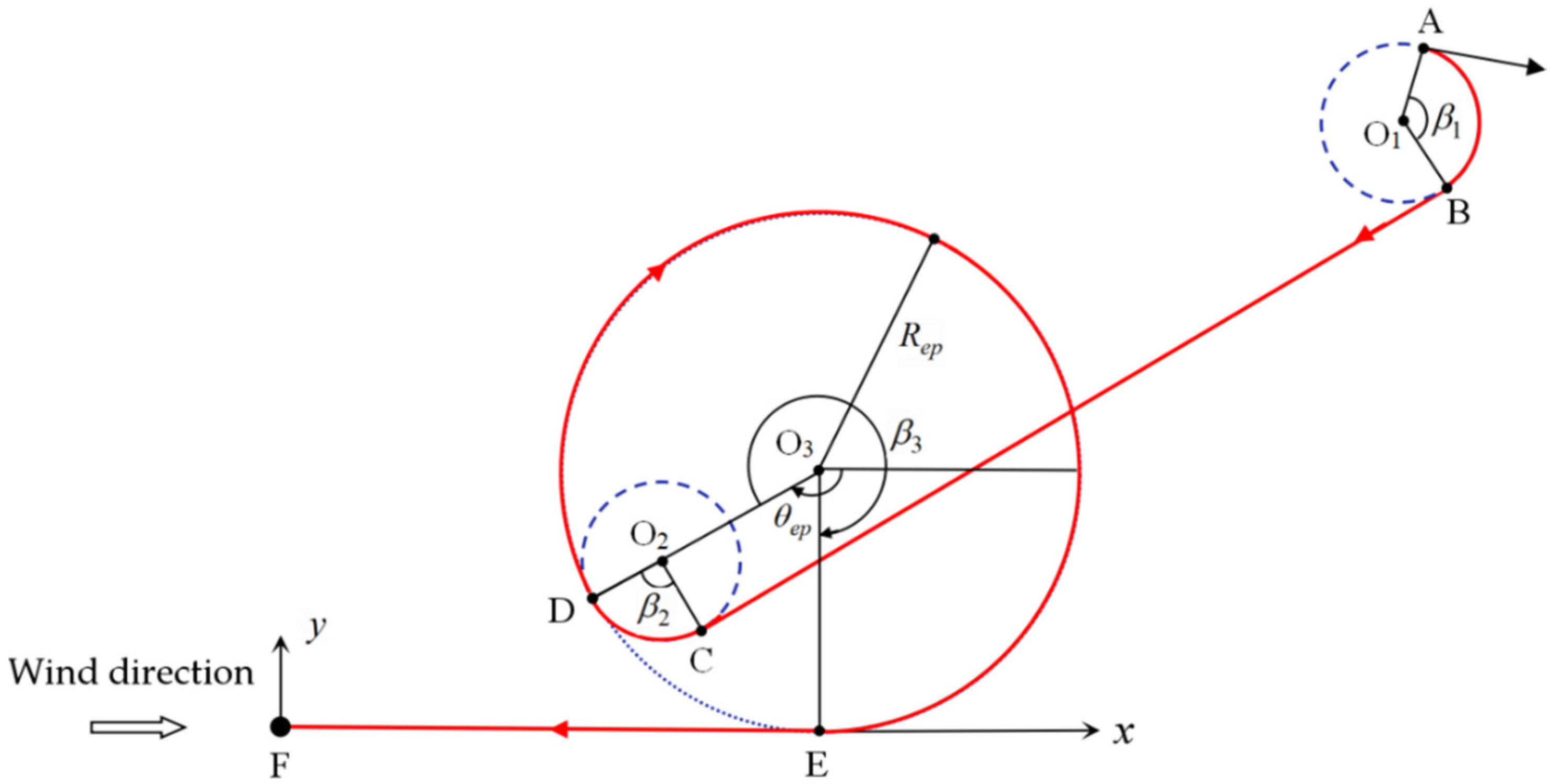
2.2.1. Trajectory Design Scheme
Based on the classical segmented trajectory design, this paper designed a new trajectory planning scheme, which not only considers the energy loss generated in the homing process, homing accuracy, and the overall flight safety of the system, but also takes into account the convenience of the bird landing operation. The specific scheme is shown in
Figure 2.
In
Figure 2,
and
are the two coordinate axes on the horizontal plane in the wind coordinate system. Axis
is perpendicular to plane
and intersects the plane
at point F. The origin F of the wind coordinate system is set as the target point, and the wind direction is consistent with the
-axis direction. Point A is the starting point of the airdrop system after parachute opening. After turning through arc AB, the parafoil airdrop system flies to the circling area near the target point, and point D is the entry point. Circle
is the center of the circle in the circling area, and the parafoil airdrop system makes a turning flight around this point with
as the radius, so as to reduce the flight altitude, and
is the angle between the line connecting the two points D and
and the positive direction of the
-axis. EF is the upwind flight phase before entering the bird’s landing, and it is tangent to the circle
.
In order to reduce the control frequency of the controller and reduce the energy loss generated as much as possible, the trajectory in
Figure 2 is designed with a single-side pull-down control method. When the parafoil system needs to adjust the flight direction, in order to achieve the purpose of fast and safe adjustment, it turns with the minimum turning radius. As shown in
Figure 1, the two arcs AB and CD are the flight direction adjustment sections, both of which are carried out with the minimum turning radius. The value range of the central angle corresponding to the two arcs is
,
, so as to reduce the control energy consumption as much as possible. The key to segment optimization is to determine the position of entry point D, which can be transformed into the calculation of the values of the two parameters
and
. In order to make the whole planned trajectory optimal, the objective function shown in Equation (3) is established to obtain the optimal values of parameters
and
.
In Equation (3), is the landing accuracy objective function, which represents the deviation between the landing point and the target point, where represents the length of the arc AB and CD, represents the length of the arc DE, and represents the length of line segments BC and EF, respectively, represents the horizontal flight distance corresponding to the initial height of the parafoil system, and is the glide ratio of the parafoil airdrop system.
2.2.2. Calculation and Constraints of Trajectory Parameters
Let
be the coordinates of the initial point,
represents the turning flight direction of the parafoil system,
is the clockwise flight,
is the counterclockwise flight,
,
is the initial heading angle, and the center positions of
and
are represented by
and
respectively, then the vector
from
to
can be calculated by Equation (4):
The included angle
between
and the positive direction of the
-axis can be calculated by Equation (5):
The included angles
,
and
of the circular arc in
Figure 1 can be calculated by Equations (6) and (7):
The parameter
in Equation (6) can be obtained by Equation (8):
In order to save the control energy as much as possible and improve the safety and stability of the airdrop system during flight, the value ranges of the agreed parameters
and
are limited by Formula (9):
In Formula (9), is the minimum turning radius allowed by the parafoil airdrop system when flying in the hovering high-flying area, corresponding to the maximum unilateral pull-down range of the parachute rope, and is the maximum turning radius.
2.3. Trajectory Optimization
The cuckoo search (CS) algorithm was proposed in 2009 [
27]. It is a bionic algorithm generated by imitating the cuckoo’s breeding and random flight behavior. The search process does not depend on the gradient and has the advantages of fewer parameters, high algorithm execution efficiency, and easy implementation. It has attracted the attention of many researchers. On this basis, many improved algorithms have been proposed to improve the overall performance of the algorithm [
28,
29,
30], and, based on the CS algorithm, combined with the piecewise trajectory design scheme proposed above, this paper searched for the optimal solution for the objective function, shown in Equation (3), within the given interval of parameters
and
, and determined the trajectory. The specific implementation steps are shown in
Figure 3.
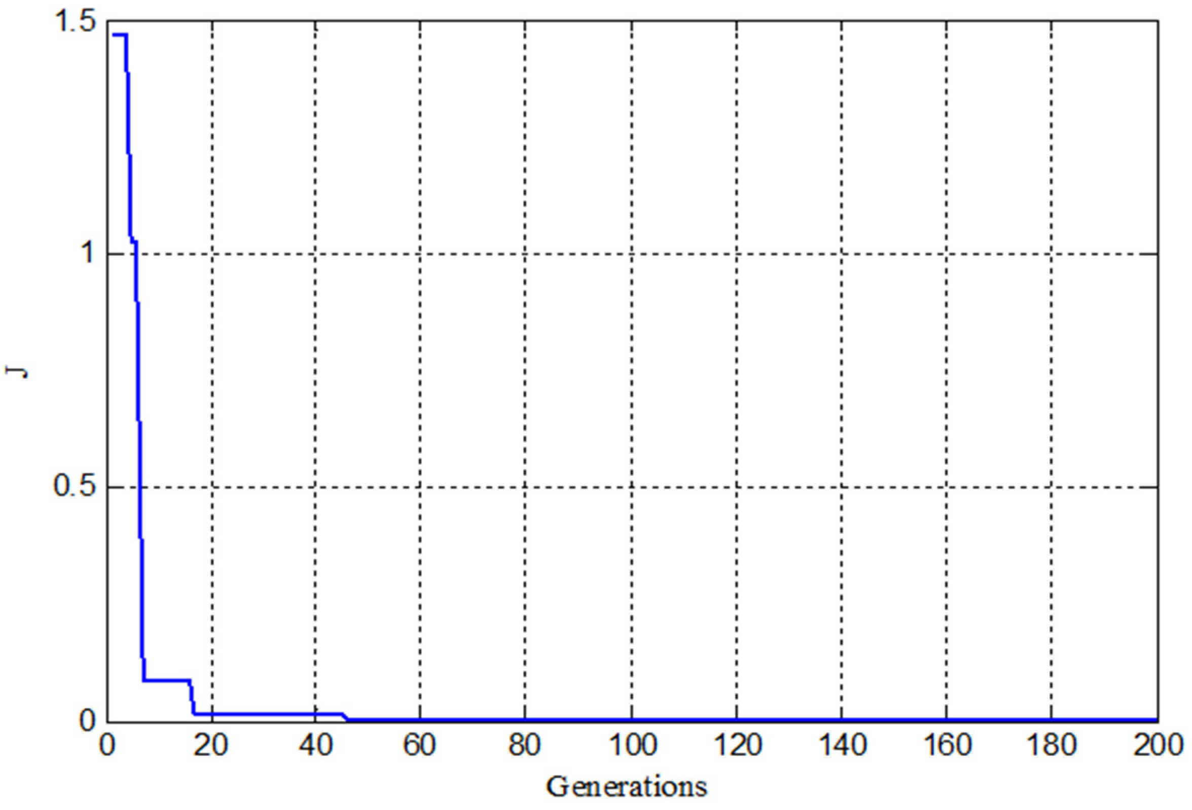
Step 1: Initialize parameters, such as population size , the maximum number of iterations, the probability of the host discovering cuckoo eggs, the starting point coordinates , the initial direction , the radius and the angle range of the entry point, and other parameters. According to the value range shown in Formula (9), a two-dimensional initial population composed of and is randomly generated, and its fitness value is calculated using the objective function shown in Equation (3).
Step 2: Generate a new levy flight solution from Equation (10) where
represents the
-th solution in the
-th generation,
,
,
, and the parameter
can be calculated by Equation (11):
Step 3: Calculate the fitness value
J of solution
A, and update the solution set according to the following rules:
Step 4: Update the solution set with the probability
of the host finding the cuckoo egg, as shown in Equation (12), where
is the Heaviside step function, and
:
Step 5: Calculate the fitness value of the solution set updated by Equation (12), and update the solution set using the rules in Step 3, then, find and save the optimal solution in the new solution set. Judge whether the search end condition is satisfied; if not, skip to step 2 for loop execution. Otherwise, end the loop and find the global optimal solution.
Step 6: Substitute the obtained optimal parameter into Equations (4)–(8) to calculate the parameters of each segment, and calculate the corresponding homing trajectory according to the initial conditions and the point-mass model of the parafoil airdrop system.
4. Discussion
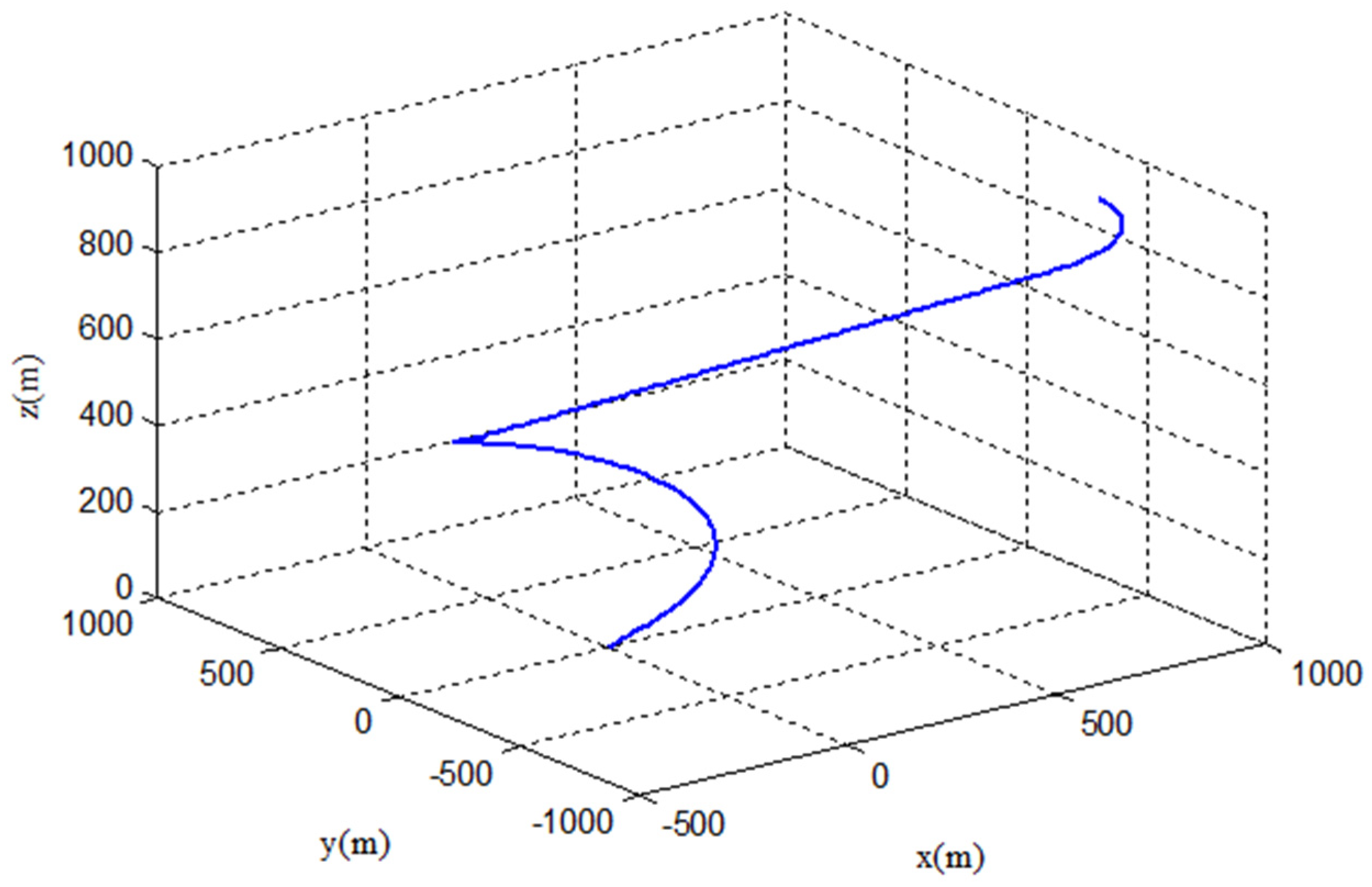
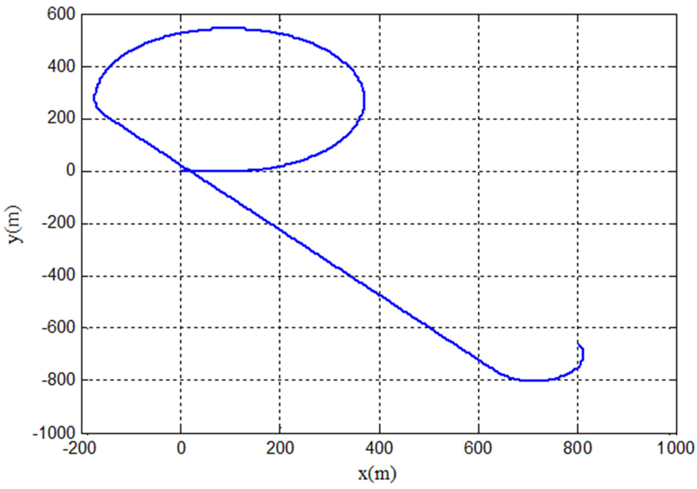
Under the same conditions, when considering the landing accuracy of the target point, the accuracy of the trajectory planned by the method in this paper is basically the same order of magnitude compared with the existing classical segmented trajectory method. For example, when the coordinates of the starting point were at (800, 800, 2000) and the initial flight direction
, the landing direction of the segmented trajectory planning strategy proposed in this paper was 3.14, and the landing error was 0.6685 m, which was about 0.3742 m higher than the accuracy of 1.0427 m in Ref. [
23].
Compared with the traditional classical segmented trajectory, the length of the glide trajectory before landing in the new scheme can be set freely according to the actual flight situation, which overcomes the defect of the length of the glide segment being affected by the radius of the parafoil circling flight circle, and has, therefore, higher landing accuracy and safety. Therefore, the segmented trajectory optimization strategy of the parafoil airdrop system given in this paper is effective and feasible.
It should be pointed out that the trajectory planning scheme designed in this paper is the basic optimal design method for the autonomous homing trajectory of the parafoil. The trajectory planning problem with constraints, such as obstacles and faults in the homing process, is not within the scope of this paper.
5. Conclusions
In the design scheme of the segmented homing of the parafoil airdrop system, the landing target point, or the position of executing the bird landing, is usually set at the center of the circling flight area. This method has the problem that the length of the straight flight segment before landing is affected by the helix radius. When the radius calculated by the optimization parameters is small, the gliding flight segment of the parafoil is shortened, which brings difficulties to the bird landing operation, or even failure to perform the bird landing successfully, resulting in damage to the airdropped material. In this paper, the segmentation scheme is improved. The straight flight segment before landing is designed at the tangent position of the spiral height elimination circle, and its length can be freely controlled. Compared with the target point designed at the center position of the spiral height elimination circle, it avoids the problem of the length of the straight flight segment before landing being subject to the spiral radius and provides a guarantee for bird landing in terms of landing accuracy and safety.
Based on the verification needs of the new trajectory scheme, this paper established the point mass model of the parafoil airdrop system. On the basis of analyzing the flight characteristics of the parafoil airdrop system, the segmentation idea and design method of the new scheme were introduced, and the calculation method of each segment trajectory analyzed. The calculation formula of the objective function and the constraint range of parameters and were given. The application method and steps of the parameter optimization of the cuckoo optimization algorithm in the new scheme were introduced in detail. In order to fully verify the feasibility of the new scheme, the trajectory under different airdrop conditions was simulated in this paper. The results showed that the correct trajectory could be successfully obtained under different initial conditions. Compared with the existing design schemes, the results show that the landing direction and accuracy of the new scheme can achieve ideal results, and the landing glide segment can be freely set and is no longer limited by the helix radius length, which proves the correctness and feasibility of the new trajectory design scheme. Moreover, the new scheme has the characteristics of simple control, high safety and easy realization in engineering. It is suitable for the trajectory planning of parafoil fixed-point airdrop systems before autonomous homing and also provides a new reference for the landing flight of parafoil airdrop systems. In future research work, we will consider more complex environmental constraints, such as obstacles, enemy areas, etc., so that the research results in this paper can be applied more widely.


