Article

Effect of Thrust on the Structural Vibrations of a Nonuniform Slender Rocket

1
Department of Mechanical & Aerospace Engineering, Nazarbayev University, Nur-Sultan 010000, Kazakhstan
2
College of Sciences & Engineering, University of Tasmania, Hobart TAS7001, Australia
*
Author to whom correspondence should be addressed.
Math. Comput. Appl. 2020, 25(2), 29; https://doi.org/10.3390/mca25020029
Submission received: 17 February 2020 / Revised: 28 April 2020 / Accepted: 28 April 2020 / Published: 15 May 2020

Abstract

:
The vibration characteristics of a nonuniform, flexible and free-flying slender rocket experiencing constant thrust is investigated. The rocket is idealized as a classic nonuniform beam with a constant one-dimensional follower force and with free-free boundary conditions. The equations of motion are derived by applying the extended Hamilton’s principle for non-conservative systems. Natural frequencies and associated mode shapes of the rocket are determined using the relatively efficient and accurate Adomian modified decomposition method (AMDM) with the solutions obtained by solving a set of algebraic equations with only three unknown parameters. The method can easily be extended to obtain approximate solutions to vibration problems for any type of nonuniform beam.

1. Introduction

The development of rockets has led to larger values of thrust-to-weight and length-to-diameter ratios as required for longer range flights. The drag force is proportional to the square of the rocket diameter, and therefore the preference is to vary the length as opposed to the diameter for a given range increase. In addition, to reduce the cost of the launching operation and initial handling and transportation, efforts are always made to reduce the rocket structural weight. These different requirements lead to a highly flexible structure, for which, dynamic response and vibrational characteristics are of great importance [1]. In general, forces acting on such a structure can be divided into conservative and non-conservative forces with the follower force (thrust) a typical example of non-conservative forces. When a given structure is both under a constant follower force and whose direction changes according to the deformation of the structure, it can undergo static divergence whereby transverse natural frequencies merge into zero and flutter, where two natural frequencies coincide resulting in the amplitude of vibration growing without bound [2].
The structural vibrations of launch vehicles have been the subject of research using various methods of calculation. The slender freely flying rocket is usually simplified as a beam with free-free boundary conditions with a follower force [3,4]. One of the first investigations of divergence and flutter was by Beal [5] where a flexible missile under constant and pulsating thrust was considered. The Galerkin method was used and it was shown that the divergence found was closely related to the first two bending moments. Wu [6,7] was the first to use a finite element technique together with the unconstrained variational approach to investigate the relation between the critical load and the eigenvalues of the system. He concluded that the optimized size and location of the concentrated mass would improve directional stability. The divergence and flutter of a spinning beam with a concentrated mass and subjected to a pulsating thrust has been investigated by Yoon and Kim [8], where they modeled the beam as a Timoshenko formulation and solved by applying a finite element method. More recently, slender rocket studies have included aerodynamic forces, gravitational forces, and internal load effects [9,10,11,12]. However, research into this area is found to be limited, with very few sustained investigations being undertaken. The present research sets a framework for future work involving more complete geometry and material discontinuities, and the ability to solve nonlinear equations, with ease, using Adomian polynomials [13].
The method of solution chosen here is the Adomian modified decomposition method [13] which is a wide-ranging method of solution for problems involving algebraic [14], differential [15], integro-differential [16], and partial differential equations [17]. Specific to this work, the Adomian decomposition and Adomian modified decomposition method have been used by several groups [18,19,20,21,22,23] for uniform and nonuniform beams, starting with either the Euler–Bernoulli or Timoshenko formulations. Mao [18] applied the Adomian modified decomposition method (AMDM) to rotating uniform beams and included a centrifugal stiffening term, Adair and Jaeger [19] applied the AMDM to rotating nonuniform beams which also included a centrifugal stiffening term, whereas Hsu et al. [20] applied the AMDM to Timoshenko beams. Lai et al. [21] and Lai et al. [22] employed both the AMDM and Adomian decomposition methods as an innovative eigenvalue solver to determine the free vibration of an Euler–Bernoulli beam under various supporting conditions. Yaman [23] used the Adomian decomposition method to investigate the influence of the orientation effect on the natural frequency of a cantilever beam carrying a tip mass, while Adair and Jaeger [24] investigated the vibrations of a beam with both a transversely and axially eccentric tip mass present using the AMDM.
The objective of the present work is to investigate the effect of the following thrust on the vibrations of a slender rocket. In order to meet this objective, the work idealizes the rocket as a nonuniform beam and the thrust as a follower force with the governing equations developed using the extended Hamilton’s principle. The AMDM is developed to calculate a solution for the dynamic analysis.

2. Structural Modeling

An assumption is made that the effect of the thrust acts only on the rocket body and does not have an influence on the fins. The body of the rocket is assumed to be a nonuniform non-extensible beam subjected to a constant follower thrust, as shown on Figure 1.
When the deformation is small,
u ( x , t ) = 0 x 1 2 ( w ( x , t ) x ) 2 d x ,
where u ( x , t ) and w ( x , t ) are the longitudinal and transverse flexible displacements along the beam respectively. Hence,
u ( x , t ) x = 1 2 ( w ( x , t ) x ) .
The kinetic energy and potential energy of the system are, respectively,
T = 1 2 0 l ρ A ( x ) ( w ( x , t ) t ) 2 d x ,
U = 1 2 0 l E I ( x ) ( 2 w ( x , t ) x 2 ) 2 d x ,
where l is length of the rocket.
The follower thrust creates virtual work and work of inertia in the lateral direction as
δ W P = P ( w ( x , t ) x δ w ( x , t ) | 0 l 0 l 2 w ( x , t ) x 2 δ w ( x , t ) d x w ( l , t ) x δ w ( l , t ) )                   = P ( w ( x , t ) x δ w ( x , t ) | x = 0 + 0 l 2 w ( x , t ) x 2 δ w ( x , t ) d x ) .
Therefore,
W = 0 l ρ A ( x ) f ( 0 x 1 2 ( w ( x , t ) x ) 2 d x ) d x ,  
where f is longitudinal acceleration.
According to Hamilton’s principle for a non-conservative system,
δ t a t b ( T + W U ) d t + t a t b δ W P d t = 0 .
On putting Equations (3)–(6) into Equation (7) and assuming that for any time interval { t a , t b } that the virtual displacement is equal to zero, the following is obtained:
2 x 2 ( E I ( x ) 2 w ( x , t ) x 2 ) + ρ A ( x ) 2 w ( x , t ) t 2 + x ( ( P f x l ρ A ( x ) d x ) w ( x , t ) x ) = 0 .
According to Sugiyama and Oshima [25], when a rocket is in its positive phase, i.e., when it is driven by the thrust of the rocket, the drag as compared with the thrust is negligible and can be neglected. Therefore, in this work the acceleration can be considered as a function of thrust and mass of the rocket. So,
P f x l ρ A ( x ) d x = P P 0 l ρ A ( x ) d x x l ρ A ( x ) d x = P 0 l ρ A ( x ) d x 0 x ρ A ( x ) d x = N ( x ) ,
giving
2 x 2 ( E I ( x ) 2 w ( x , t ) x 2 ) + ρ A ( x ) 2 w ( x , t ) t 2 + x ( N ( x ) w ( x , t ) x ) = 0 .
It is assumed that the cross-sectional area and moment of inertia of the rocket body vary according to
A ( x ) = A 0 ( 1 + ( α 1 ) x l ) 2 ,
I ( x ) = I 0 ( 1 + ( α 1 ) x l ) 4 ,
where α = b 1 / b 0 is the ratio of the rocket cross-sectional diameters just before the nose cone and at the base. Here, A 0 = π b 0 2 / 4 and I 0 = π b 0 4 / 64 are the cross-sectional area and moment of inertia at x = 0 , respectively.
After setting β = 1 α , and setting M = 0 l ρ A ( x ) d x , N ( x ) in Equation (10) can be written as
P ρ A 0 M 0 x ( 1 2 β x l + β 2 ( x l ) 2 ) d x ,
which leads to
N ( x ) = P ρ A 0 3 M [ 3 x 3 β l x 2 + β 2 l 2 x 3 ] .
In addition, according to modal analysis for harmonic free vibration, w ( x , t ) can be separated in space and time as
w ( x , t ) = φ ( x ) h ( t ) ,
where φ ( x ) is the modal deflection and h ( t ) is the harmonic function of time. If ω denotes the circular frequency of h ( t ) , then 2 w ( x , t ) / t 2 = ω 2 φ ( x ) h ( t ) and the eigenvalue of the problem of Equation (10) reduces to the differential equation
d 2 d x 2 [ ( 1 β x l ) 4 d 2 φ ( x ) d x 2 ] + P ρ A 0 l 3 E I 0 M d d x [ [ 3 x l 3 β ( x l ) 2 + β 2 ( x l ) 3 ] d φ ( x ) d x ] ρ A 0 ω 2 E I 0 ( 1 β x l ) 2 φ ( x ) = 0 .
Without loss of generality, the following dimensionless quantities are introduced:
η = x l ,     φ ( η ) = φ ( x ) l ,     λ 1 = ρ A 0 ω 2 l 4 E I 0 ,     λ 2 = P ρ A 0 3 E I 0 M .
Equation (16) can now be written as
d 2 d η 2 [ ( 1 β η ) 4 d 2 φ ( η ) d η 2 ] + λ 2 d d η [ [ 3 η 3 β η 2 + β 2 η 3 ] d φ ( η ) d η ] λ 1 ( 1 β η ) 2 φ ( η ) = 0 .
Equation (17) is expanded as
d 4 φ ( η ) d η 4 8 β ( 1 β η ) d 3 φ ( η ) d η 3 + [ 12 β 2 ( 1 β η ) 2 + λ 2 ( 3 η 3 β η 2 + β 2 η 3 ) ( 1 β η ) 4 ] d 2 φ ( η ) d η 2 λ 1 ( 1 β η ) 2 φ ( η ) = 0 .

3. Boundary Conditions

Generally, the boundary conditions can be considered as
E I ( x ) 2 w ( x , t ) x 2 | x = 0 = E I ( x ) 3 w ( x , t ) x 3 | x = l = 0 ,
x ( E I ( x ) 2 w ( x , t ) x 2 ) | x = 0 = x ( E I ( x ) 3 w ( x , t ) x 3 ) | x = l = 0 .
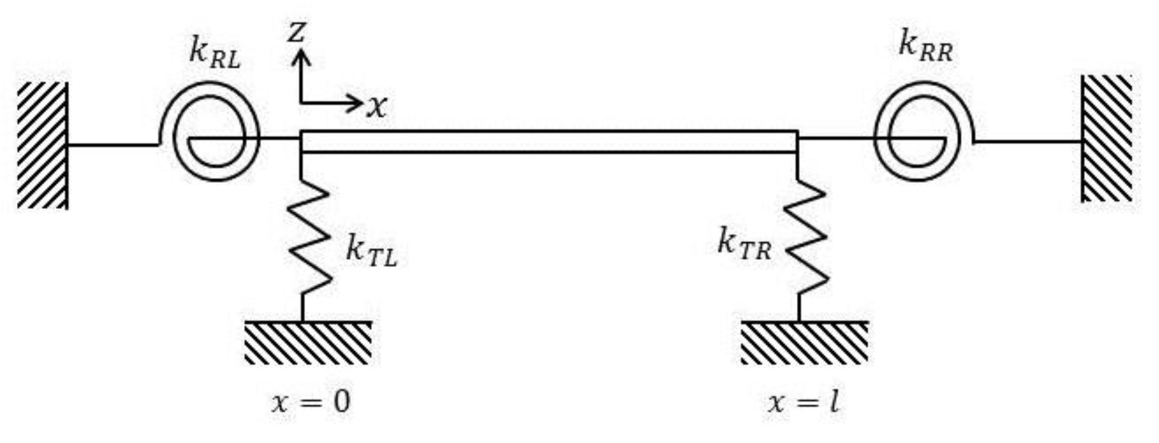
With reference to Figure 2, the boundary conditions, which do not vary with time and considered in dimensionless form, can be written as follows:
d 2 φ ( η ) d η 2 | η = 0 K R L d φ ( η ) d η | η = 0 = 0 ,        d 3 φ ( η ) d η 3 | η = 0 4 β d 2 φ ( η ) d η 2 | η = 0 + K T L φ ( η ) | η = 0 = 0 ,
d 2 φ ( η ) d η 2 | η = 1 + K R R d φ ( η ) d η | η = 1 = 0 ,        d 3 φ ( η ) d η 3 | η = 1 4 β 1 β d 2 φ ( η ) d η 2 | η = 1 K T R φ ( η ) | η = 1 = 0 ,
where the coefficients are in nondimensionalized form with
K T L = k T L l 3 E I 0 ,     K T R = k T R l 3 E I 1 ,     K R L = k R L l E I 0 ,     K R R = k R R l E I 1 ,
where I 1 is the moment of inertia at x = l .

4. Application of AMDM

According to the AMDM, φ ( η ) in Equation (18) can be expressed as an infinite series, i.e.,
φ ( η ) = m = 0 C m η m ,
where the unknown coefficients C m are determined recurrently. If a linear operator G d 4 / d η 4 is used, then the inverse operator of G is a four-fold integral operator defined as
G 1 = 0 η 0 η 0 η 0 η ( ) d η d η d η d η .
Equation (18) can now be written as
φ ( η ) = Φ ( η ) + G 1 { 8 β ( 1 β η ) d 3 φ ( η ) d η 3 [ 12 β 2 ( 1 β η ) 2 + λ 2 ( 3 η 3 β η 2 + β 2 η 3 ) ( 1 β η ) 4 ] d 2 φ ( η ) d η 2 + λ 1 ( 1 β η ) 2 φ ( η ) } .
By substituting the decomposition φ ( η ) = m = 0 C m η m into Equation (25), the following is obtained:
φ ( η ) = Φ ( η ) + G 1 { 8 β ( 1 β η ) m = 0 ( m + 1 ) ( m + 2 ) ( m + 3 ) C m + 3 η m [ 12 β 2 ( 1 β η ) 2 + λ 2 ( 3 η 3 β η 2 + β 2 η 3 ) ( 1 β η ) 4 ] m = 0 ( m + 1 ) ( m + 2 ) C m + 2 η m + λ 1 ( 1 β η ) 2 m = 0 C m η m } ,
where Φ ( η ) = m = 0 3 C m η m = φ ( 0 ) + φ ( 0 ) η + φ ( 0 ) η 2 / 2 + φ ( 0 ) / 6 is the initial term.
The following are a list of power series:
( 1 β η ) 1 = j = 0 ( β η ) j ,     β 0 , ( 1 β η ) 2 = j = 0 ( j + 1 ) ( β η ) j ,         β 0 , ( 1 β η ) 4 = j = 0 ( j + 1 ) ( j + 2 ) ( j + 3 ) 6 ( β η ) j ,         β 0 .
Using these relationships, the following are obtained:
( 1 β η ) 1 m = 0 ( m + 1 ) ( m + 2 ) ( m + 3 ) C m + 3 η m = m = 0 η m j = 0 m β m j ( j + 1 ) ( j + 2 ) ( j + 3 ) C j + 3 .
( 1 β η ) 2 m = 0 ( m + 1 ) ( m + 2 ) C m + 2 η m = m = 0 η m j = 0 m β m j ( m j + 1 ) ( j + 1 ) ( j + 2 ) C j + 2 .
( 1 β η ) 4 m = 0 ( m + 1 ) ( m + 2 ) C m + 2 η m = m = 0 j = 0 m β m j ( m j + 1 ) ( m j + 2 ) ( m j + 3 ) 6 ( j + 1 ) ( j + 2 ) C j + 2 .
On integrating Equation (26) and incorporating Equations (28)–(30)
m = 0 C m η m = φ ( 0 ) + φ ( 0 ) η + φ ( 0 ) 2 η 2 + φ ( 0 ) 6 η 3 + m = 0 { η m + 4 ( m + 1 ) ( m + 2 ) ( m + 3 ) ( m + 4 ) j = 0 m 8 β m j + 1 ( j + 1 ) ( j + 2 ) ( j + 3 ) C j + 3 ( j + 1 ) ( j + 2 ) [ 12 β m j + 2 ( m j + 1 ) + λ 2 ( 3 η 3 β η 2 + β 2 η 3 ) β m j ( m j + 1 ) ( m j + 2 ) ( m j + 3 ) 6 ] C j + 2 + λ 1 β m j ( m j + 1 ) C j } .
The recurrence relation for the coefficients C k can now be stated as
C 0 = φ ( 0 ) ,     C 1 = φ ( 0 ) ,     C 2 = φ ( 0 ) 2 ,     C 3 = φ ( 0 ) 6 ,
and for m 4 as
C m = 1 m ( m 1 ) ( m 2 ) ( m 3 ) j = 0 m 4 ( j + 1 ) ( j + 2 ) ( j + 3 ) 8 β m j 3 C j + 3 ( j + 1 ) ( j + 2 ) [ β m j 2 ( m j 3 ) + λ 2 ( 3 η 3 β η 2 + β 2 η 3 ) β m j 4 ( m j 3 ) ( m j 2 ) ( m j 1 ) 6 ] C j + 2 + λ 1 β m j 4 ( m j 3 ) C j } .
The coefficients C m can be found from the recurrent Equations (32) and (33) and the solution for φ ( η ) subsequently calculated from Equation (26). The series solution is φ ( η ) = m = 0 C m η m , although all of the coefficients C m cannot be determined, and thus the solutions must be approximated by the truncated series m = 0 n 1 C m η m . The successive approximations are φ [ n ] ( η ) = m = 0 n 1 C m η m , as n increases and the boundary conditions are met.
Thus, φ [ 1 ] ( η ) = C 0 ,     φ [ 2 ] ( η ) = φ [ 1 ] ( η ) + C 1 η ,     and   φ [ 3 ] ( η ) = φ [ 2 ] + C 2 η 2 serve as approximate solutions with increasing accuracy as n . The four coefficients C m ( m = 0 ,   1 ,   2 ,   3 ) in Equation (32) depend on the boundary conditions of Equations (21) and (22). As in this case, the boundary conditions are free-free, so K R R 0 , K T R 0 , K R L 0 , K T L 0 , and so it is most convenient to choose the two coefficients C 0 and C 1 as zero, and the other two coefficients C 2 and C 3 as arbitrary constants with the coefficients C m obtained using Equation (33). By substituting φ [ n ] ( η ) = m = 0 n 1 C m η m into the last two boundary conditions of Equation (22) two algebraic equations involving C 2 and C 3 are obtained
m = 0 n 3 ( m + 1 ) ( m + 2 ) C m + 2 = f 12 [ n ] ( λ 1 ) C 2 + f 13 [ n ] ( λ 1 ) C 3 = 0 ,
m = 0 n 4 ( m + 1 ) ( m + 2 ) ( m + 3 ) C m + 3 = f 22 [ n ] ( λ 1 ) C 2 + f 23 [ n ] ( λ 1 ) C 3 = 0 ,
and for non-trivial solutions of C 2 and C 3 the frequency equation can be written as
f 12 [ n ] ( λ 1 ) f 23 [ n ] ( λ 1 ) f 22 [ n ] ( λ 1 ) f 13 [ n ] ( λ 1 ) = 0 .
The ith estimated eigenvalue λ 1 ( i ) [ n ] corresponding to n is obtained from Equation (36), i.e., the ith estimated dimensionless natural frequency Ω n ( i ) [ n ] = λ 1 ( i ) [ n ] is also obtained and n is determined by the following equation:
| Ω n ( i ) [ n ] Ω n ( i ) [ n 1 ] | ε ,
where Ω n ( i ) [ n 1 ] is the ith estimated dimensionless natural frequency corresponding to n 1 and ε is a preset sufficiently small value. If Equation (37) is satisfied, then Ω n ( i ) [ n ] is the ith dimensionless natural frequency Ω n ( i ) . By substituting Ω n ( i ) [ n ] into Equation (36), we obtain
C 3 = f r 2 [ n ] ( Ω n ( i ) [ n ] ) f r 3 [ n ] ( Ω n ( i ) [ n ] ) C 2 ,   r = 1 , 2 ,
and all of the other coefficients C m can be obtained from Equations (32) and (33). In addition, the ith mode shape φ i [ n ] corresponding to the ith eigenvalue Ω n ( i ) [ n ] is obtained by
φ i [ n ] ( η ) = m = 0 n 1 C m [ i ] η m ,
where C m [ i ] is C m ( η ) in which λ 1 is substitutes by λ 1 ( i ) and φ i [ n ] is the ith eigenfunction corresponding to the ith eigenvalue λ 1 ( i ) . By normalizing Equation (39), the ith normalized eigenfunction is defined as
φ ¯ i [ n ] ( η ) = φ i [ n ] ( η ) 0 1 [ φ i [ n ] ] 2 d η ,
where φ ¯ i [ n ] ( η ) is the ith mode shape function of the beam corresponding to the ith natural frequency ω i [ n ] = λ 1 ( i ) [ n ] E I 0 ρ A 0 l 4 = Ω n ( i ) [ n ] E I 0 ρ A 0 l 4 .

5. Numerical Results

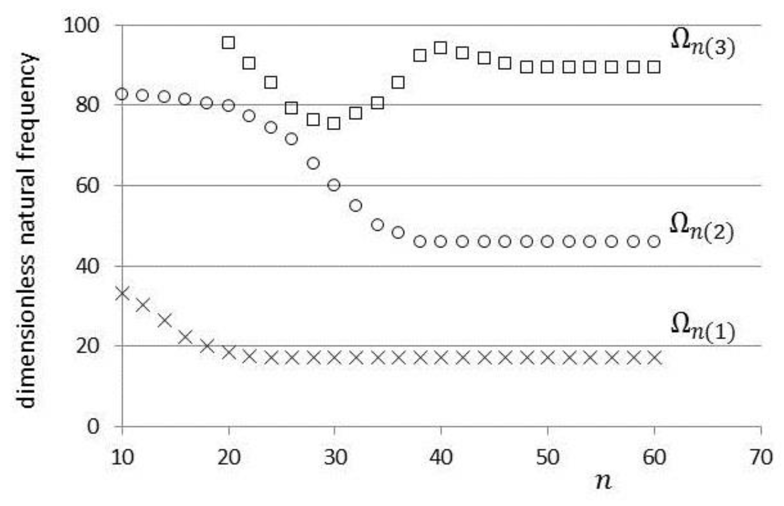
The convergence plots for the first three dimensionless natural frequencies, with the truncation factor, β set at 0.25 and thrust set at zero, are shown in Figure 3. By solving Equation (36) for n and taking the real root for λ 1 ( 1 ) = Ω n ( 1 ) 2 , it can be shown that for n = 42
| Ω n ( 1 ) [ 42 ] Ω n ( 1 ) [ 41 ] ε = 0.00001 | ,
with
Ω n ( 1 ) Ω n ( 1 ) [ 42 ] = 15.1278 .
For this particular case, it was found that convergence occurred for Ω n ( 1 ) after 42 iterations, for Ω n ( 2 ) after 52 iterations, and for Ω n ( 3 ) after 60 iterations. It is considered that the convergence is quite rapid for each of the natural frequencies.
The development method of solution was in part validated with published results. In Table 1, a comparison is made with the results of Krynicki and Mazurkiewicz [26] for a solid cylindrical beam with free-free boundary conditions and with the thrust set at zero. It can be found that there is reasonable agreement between the two sets of results, although, generally, the current method gives slightly higher solutions for all three natural frequencies.
Calculations were also made and compared with published data for a “complete” cone, which means the cone was not truncated but sharp when η = 1 . The boundary conditions were again free-free and the thrust was set to zero. As can be seen from Table 2, there was fairly good agreement with those reported by Naguleswaran [27], although, again, the current method gave higher results for each of the natural frequencies.
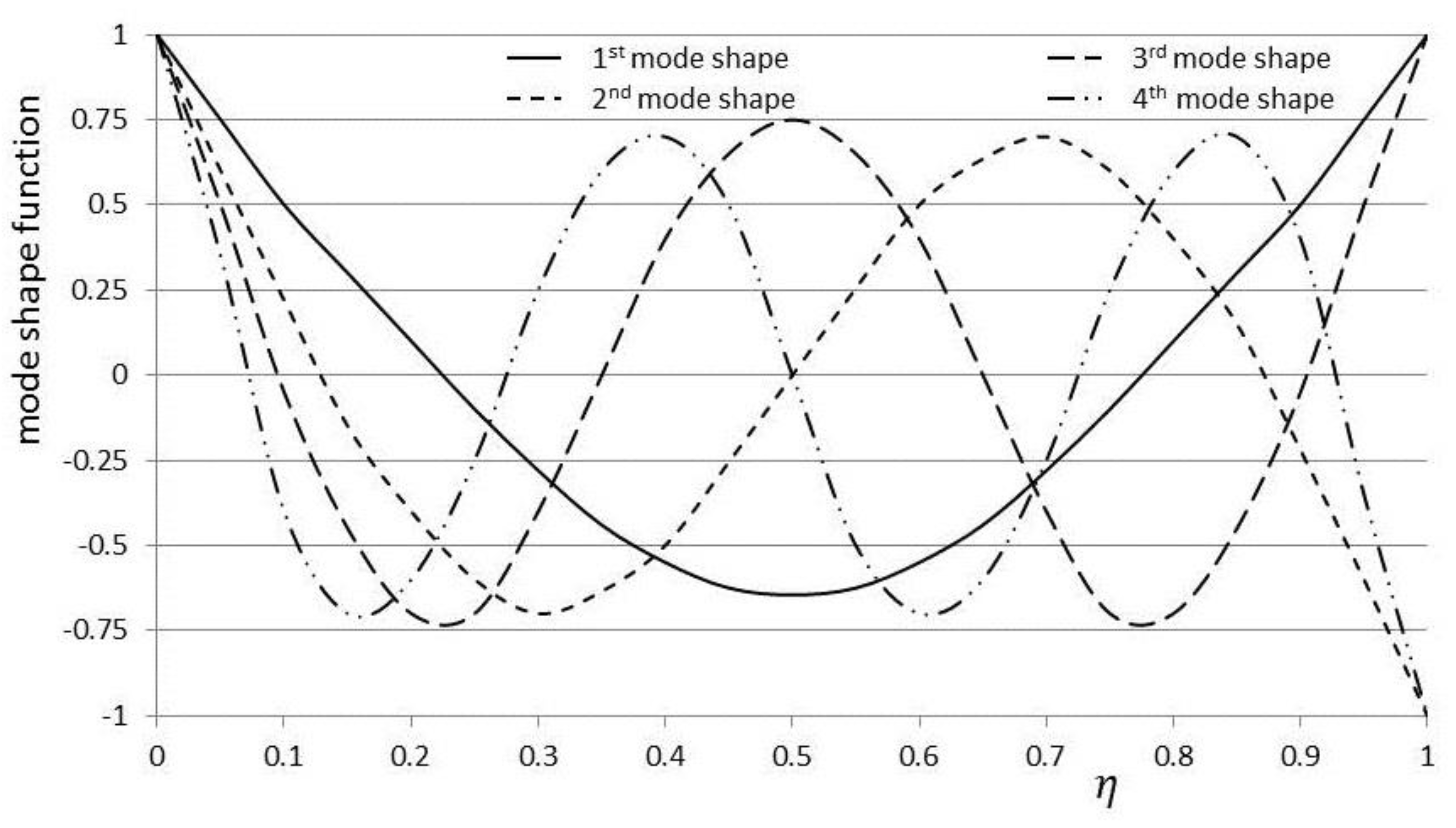
By substituting Ω n ( 1 ) [ 42 ] as given by Equation (42) into Equations (33) and (39) (with λ 2 = 0 ) and normalizing using Equation (40), a polynomial can be obtained to describe the first mode shape function. The same procedure was employed for other natural frequencies and mode shapes. The mode shapes related to the first four natural frequencies are shown on Figure 4.
The variation of the natural frequencies with the truncation factor, again without thrust, is given in Table 3. It can be seen that the values are in reasonable agreement with those reported by Naguleswaran [27]. Additionally, it is notable that the first natural frequency does not vary monotonically with β , whereas the second and third natural frequencies do.
As may be intuitively obvious, the increase in thrust force will reduce the natural frequencies. The calculations made for the first three modes for increasing nondimensional thrust values and for different truncation factors, β , are shown in Table 4. As can be seen, the increases in thrust have a considerable effect on the reduction of all three natural frequencies for each of the β values. For example, for the first natural frequency when β = 0.05 , there is a large reduction in natural frequency of approximately 63%.
To find the effect of the increase in thrust on mode shape, calculations were made with increasing nondimensional thrust values, λ 2 for the fundamental mode shape. The increase in thrust is seen in Figure 5 to reduce the magnitude of the mode shape in the vicinity of the aft of the rocket, i.e., close to the application of the thrust, whilst close to the rocket nose the magnitude of the mode shape increases. This phenomenon, according to Pourtakdoust and Assadian [1] motivates inertial measuring units (IMU) induced vibrations on considering the forward location of the IMU. In Pourtakdoust and Assadian [28] it was found that the IMU location in the aft of the vehicle could lead to dynamic instability. Increasing thrust caused a backward shift in the extremum point of the fundamental mode shape curve which allowed for a larger margin of safety for the IMU induced vibration.
Finally, to show the ease of changing boundary conditions, and for further validation, a comparative study with calculations obtained by a finite-element method (FEM) for various boundary conditions was undertaken. The analytical results were compared with the results obtained using the commercial FEM software ANSYS [29] and previously reported by Avcar [30].
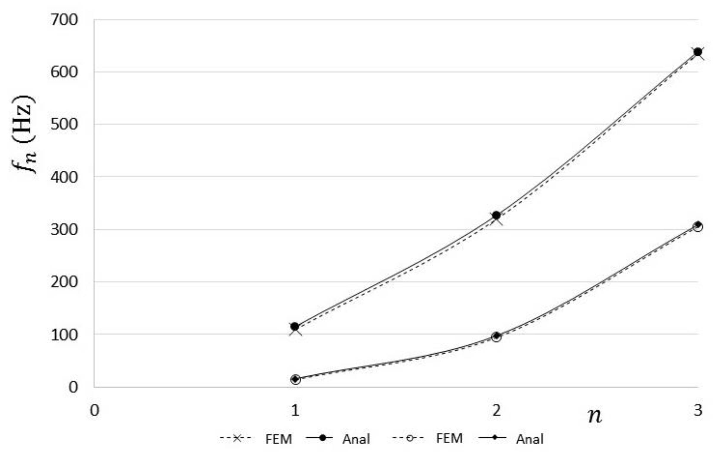
In this study, the beam had a constant square cross-section and homogeneous material properties. The analytical calculations were converted to dimensional quantities for the purpose of comparison, with E = 70 × 10 9 N/m2, ρ = 2700 kg/m3, l = 3 m, and A = 0.03 m2. The boundary conditions used were, clamped-clamped and clamped-free, respectively. For the clamped-clamped case, the nondimensional coefficients for translation and rotation, as found in Equations (21) and (22), become K R L ,   K R R ,   K T L ,   K T R . For the clamped-free case, K R L ,   K R R 0 ,   K T L ,   K T R 0 . The comparison between the current method and the finite-element method is shown in Figure 6, where f n and n are the natural frequency and mode number, respectively.
As can be seen, the two methods of calculation give close results, although the AMDM calculations tend to be consistently slightly higher. The maximum discrepancy found between the two calculation methods was 0.132%.

6. Conclusions

The proposed method has been effective in obtaining the closed-form of the free vibration of a slender rocket with free-free boundary conditions. The ith natural frequency and mode shape function can be derived using this method, with the results of this relatively simple approach obtaining results similar to more complex methods. Two specific advantages of using the AMDM approach are the fast convergence rates noted and the high accuracy of the calculations. A practical advantage of using AMDM is that boundary conditions can be easily changed for different scenarios.

Author Contributions

Methodology, Supervision and Writing—original draft, D.A.; Investigation and Writing—review and editing, A.N. and M.J.; Software, A.N. All authors have read and agreed to the published version of the manuscript.

Funding

This investigation is supported by the Nazarbayev University Small Competitive Grant No. 090118FD5317.

Conflicts of Interest

The authors declare no conflict of interest.

References

  1. Pourtakdoust, S.H.; Assadian, N. Investigation of thrust effect on the vibrational characteristics of flexible guided missiles. J. Sound Vib. 2004, 272, 287–299. [Google Scholar] [CrossRef]
  2. Kim, J.H.; Choo, Y.-S. Dynamic stability of a free-free Timoshenko beam subjected to a pulsating follower force. J. Sound Vib. 1998, 216, 623–636. [Google Scholar] [CrossRef]
  3. Bolotin, V.V. Nonconservative Problem of the Theory of Elastic Stability; Pergamon Press: New York, NY, USA, 1963. [Google Scholar]
  4. Yun, X.; Changchuan, X.; Chao, Y. Effect of thrust on aeroelastic stability of a slender missile. In Proceedings of the 49th AIAA/ASME/ASCE/AHS/ASC Structures, Structural Dynamics and Materials Conference, Schaumburg, IL, USA, 7–10 April 2008. [Google Scholar]
  5. Beal, T.R. Dynamic stability of a flexible missile under constant and pulsating thrust. J. Aircraft. 1965, 3, 486–494. [Google Scholar] [CrossRef]
  6. Wu, J.J. On the stability of a free-free beam under axial thrust subjected to directional control. J. Sound Vib. 1975, 43, 45–52. [Google Scholar] [CrossRef]
  7. Wu, J.J. Missile stability using finite elements-An unconstrained variational approach. AIAA J. 1976, 14, 313–319. [Google Scholar] [CrossRef]
  8. Yoon, S.H.; Kim, J.H. A concentrated mass on the spinning unconstrained beam subjected to a thrust. J. Sound Vib. 2002, 254, 621–634. [Google Scholar] [CrossRef]
  9. Trikha, M.; Roy Mahapatra, D.; Gopalakrishnan, S.; Pandivan, R. Structural stability of slender aerospace vehicles: Part 1 Mathematical Modeling. Int. J. Mech. Sci. 2010, 52, 937–951. [Google Scholar] [CrossRef]
  10. Hodges, D.H. A New Approach to Aeroelastic Response, Stability and Loads of Missiles and Projectiles. Available online: https://pdfs.semanticscholar.org/82dc/e823900602140105fff85506f1727271c10f.pdf (accessed on 29 April 2020).
  11. Ohshima, T.; Sugiyama, Y. Effect of Aerodynamic Loads on Dynamic Stability of Slender Launch Vehicle Subjected to An End Rocket Thrust; American Society of Mechanical Engineers: New York, NY, USA; New Orleans, LA, USA, 2002. [Google Scholar]
  12. Lamorte, N.; Friedmann, P.P. Hypersonic aeroelastic and aerothermoelastic studies using computational fluid dynamics. AIAA J. 2014, 52, 2062–2078. [Google Scholar] [CrossRef] [Green Version]
  13. Adomain, G. A review of the decomposition method in applied mathematics. J. Math. Anal. Appl. 1988, 135, 501–544. [Google Scholar] [CrossRef] [Green Version]
  14. Adomian, G. On the solution of algebraic equations by the decomposition method. J. Math. Anal. Appl. 1985, 105, 141–166. [Google Scholar] [CrossRef] [Green Version]
  15. Adomian, G. Nonlinear Stochastic System Theory and Application to Physics, Kluwer Academic; Springer: New York, USA, 1988. [Google Scholar]
  16. Adomian, G.; Rach, R. On composite nonlinearities and the decomposition method. J. Math. Anal. Appl. 1986, 113, 504–509. [Google Scholar] [CrossRef] [Green Version]
  17. Wazwaz, A.M. Analytic treatment for variable coefficient fourth-order parabolic partial differential equations. Appl. Math. Comput. 2001, 123, 219–227. [Google Scholar] [CrossRef]
  18. Mao, Q. Application of adomain modified decomposition method to free vibration analysis of rotating beams. Math. Probl. Eng. 2013. [Google Scholar] [CrossRef]
  19. Adair, D.; Jaeger, M. Simulation of tapered rotating beams with centrifugal stiffening using the Adomian decomposition method. Appl. Math. Model. 2016, 40, 3230–3241. [Google Scholar] [CrossRef]
  20. Hsu, J.-C.; Lai, H.-Y.; Chen, C.-K. An innovative eigenvalue problem solver for free vibration of uniform Timoshenko beams using the Adomian modified decomposition method. J. Sound Vib. 2009, 325, 451–470. [Google Scholar] [CrossRef]
  21. Lai, H.-Y.; Chen, C.-K.; Hsu, J.-C. Free vibration of non-uniform Euler-Bernoulli beams by the Adomian modified decomposition method. CMES Comput. Model. Eng. Sci. 2008, 34, 87–113. [Google Scholar]
  22. Lai, H.-Y.; Hsu, J.-C.; Chen, C.-K. An innovative eigenvalue problem solver for free vibration of Euler-Bernoulli beam by using the Adomian decomposition method. Comput. Math. Appl. 2008, 56, 3204–3220. [Google Scholar] [CrossRef] [Green Version]
  23. Yaman, Y. Adomian decomposition method for solving a cantilever beam of varying orientation with tip mass. J. Comput. Nonlinear Dyn. 2007, 2, 52–57. [Google Scholar] [CrossRef]
  24. Adair, D.; Jaeger, M. Simulation of the vibrations of a non-uniform beam loaded with both transversely and axially eccentric tip mass. Int. J. Comput. Methods Exp. Meas. 2018, 6, 679–690. [Google Scholar] [CrossRef] [Green Version]
  25. Sugiyama, Y.; Oshima, T. Effect of Aerodynamic Loads on Dynamic Stability of Slender Launch Vehicle Subjected to An End Rocket Thrust; Paper IMECE 2002-33034, FSI, AE & FIV + N Symposium; ASME: New Orleans, LA, USA; New York, NY, USA, 2002. [Google Scholar]
  26. Krynicki, E.; Mazurkiewicz, Z. Free vibration of a simply supported bar with a linearly variable height of cross section. Trans. Am. Soc. Mech. Eng. J. Appl. Mech. (Series E) 1962, 29, 497–501. [Google Scholar] [CrossRef]
  27. Naguleswaran, S. A direct solution for the transverse vibration of Euler-Bernoulli wedge and cone beams. J. Sound Vib. 1994, 172, 289–304. [Google Scholar] [CrossRef]
  28. Pourtakdoust, S.H.; Assadian, N. Aeroelastic Simulation of Guided Missiles; M. S. Project; Sharif University of Technology: Tehran, Iran, 2001. [Google Scholar]
  29. ANSYS. Academic Research; Ansys Inc.: Canonsburg, PA, USA, 2014. [Google Scholar]
  30. Avcar, M. Free vibration analysis of beams considering different geometric characteristics and boundary conditions. Int. J. Mech. Appl. 2014, 4, 94–100. [Google Scholar] [CrossRef]
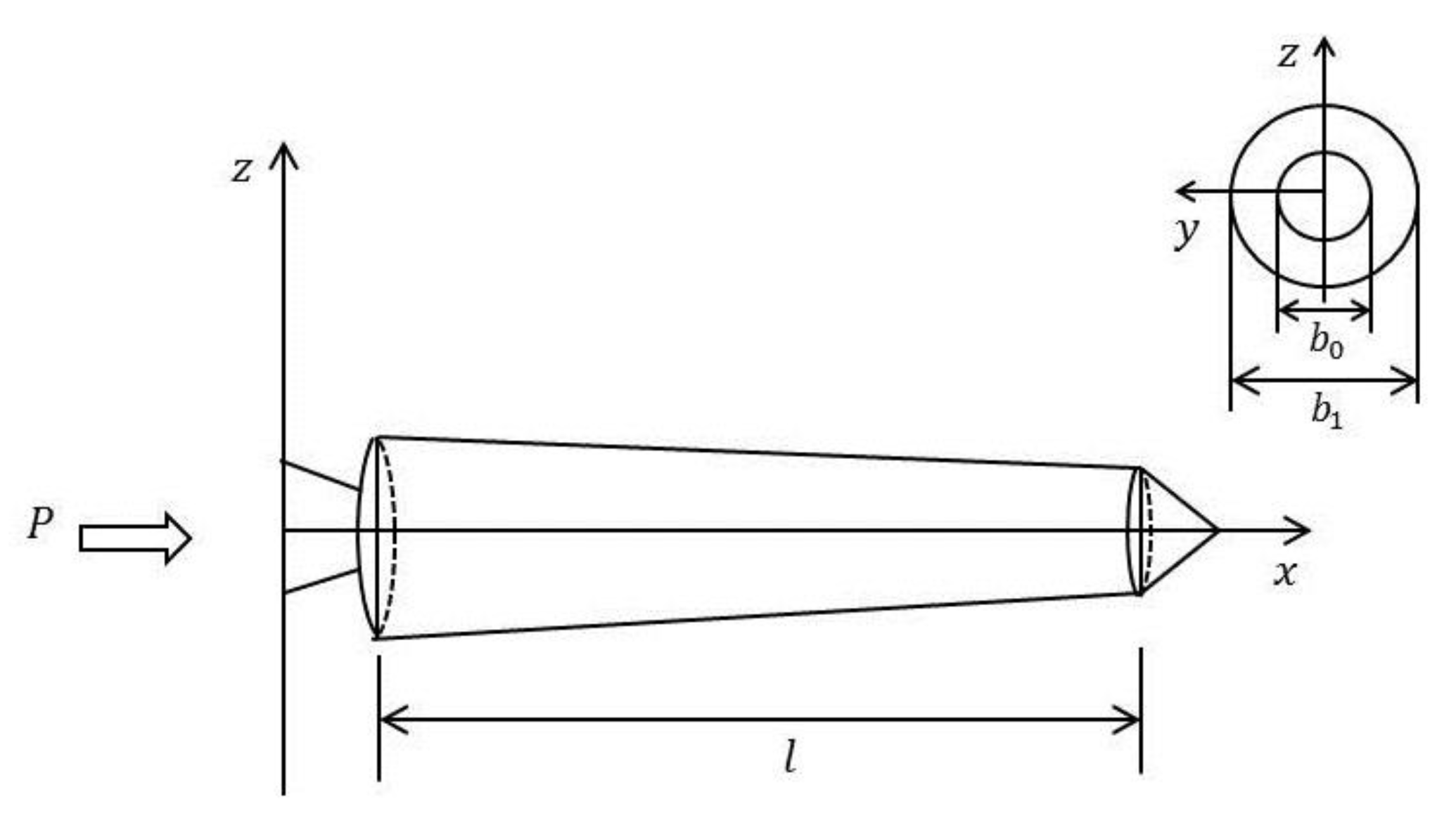
Figure 1. Simplified nonuniform rocket body subjected to constant thrust.
Mca 25 00029 g001
Figure 2. Boundary conditions using translational and rotational spring coefficients.
Mca 25 00029 g002
Figure 3. Convergence plots for the first three dimensionless natural frequencies when β = 0.25 .
Mca 25 00029 g003
Figure 4. The first four mode shape functions for β = 0.5 .
Mca 25 00029 g004
Figure 5. Effect of thrust magnitude on the first mode shape function, for β = 0.5 .
Mca 25 00029 g005
Figure 6. Comparisons between the analytical calculations and those obtained using a finite-element method.
Mca 25 00029 g006
Table 1. Frequency parameters of a uniform beam with circular cross-section with free-free boundary conditions.
Uniform Cylinder, β = 0.0
Ω n ( 1 ) Ω n ( 2 ) Ω n ( 3 )
Current22.374561.6912121.0452
Ref. [26]22.373361.6728120.9030
Table 2. Frequency parameters of a “complete” rocket as compared with the frequency parameters of a free-free complete cone.
‘Complete’ Rocket, β = 1.0
Ω n ( 1 ) Ω n ( 2 ) Ω n ( 3 ) Ω n ( 4 )
Current17.419535.043657.486784.8549
Ref. [27]17.416435.027057.379684.6028
Table 3. First three dimensionless natural frequencies of a free-free truncated cone for different truncation factors, β with free-free boundary conditions.
Truncated Cone
β Ω n ( 1 ) Ω n ( 2 ) Ω n ( 3 )
0.05Current15.955133.125956.5495
Ref. [27]15.954333.125156.5484
0.15Current14.939934.854263.8621
Ref. [27]14.938134.853563.8434
0.25Current15.127837.897671.5367
Ref. [27]15.126637.897271.5171
0.35Current15.768141.120578.8673
Ref. [27]15.767441.119378.8259
0.45Current16.613544.354386.0330
Ref. [27]16.613044.353785.8162
0.55Current17.566247.566790.2381
Ref. [27]17.565347.5650-
0.65Current18.580350.675193.7655
Ref. [27]18.5794--
Table 4. Effect of thrust magnitude on the natural frequency of the first three modes.
Truncated Cone
β Ω n ( 1 ) Ω n ( 2 ) Ω n ( 3 )
0.05 λ 2 = 0 15.955133.125956.5495
λ 2 = 1 11.966322.724335.3434
λ 2 = 2 7.645114.277322.9732
λ 2 = 3 5.956110.279016.7838
0.25 λ 2 = 0 15.127837.897671.5367
λ 2 = 1 11.030625.770044.7104
λ 2 = 2 6.933616.333629.0618
λ 2 = 3 5.988111.786121.2321
0.65 λ 2 = 0 18.580350.675193.7655
λ 2 = 1 13.161034.960860.9476
λ 2 = 2 8.128922.297039.3815
λ 2 = 3 6.580416.216028.1300