Article

Aerodynamic Optimization of a 10 kW Radial Inflow Turbine with Splitter Blades

School of Energy and Power Engineering, Huazhong University of Science and Technology, Wuhan 430074, China
*
Author to whom correspondence should be addressed.
Processes 2021, 9(7), 1256; https://doi.org/10.3390/pr9071256
Submission received: 4 June 2021 / Revised: 28 June 2021 / Accepted: 13 July 2021 / Published: 20 July 2021

Abstract

:
The application of splitter blades can improve passage obstructions and reduce flow loss of small-scale organic Rankine cycle (ORC) radial inflow turbines. In this study, taking R245fa as the working fluid, splitter blades are applied to design an impeller layout for a 10 kW ORC radial inflow turbine, and numerical simulation is conducted on different impeller schemes through Fluent 15.0. The influence of the meridian length and circumferential position of the splitter blade on the performance of the turbine impeller is studied. The results show that the meridian length and circumferential position of the splitter blade exert greater effects on the flow field distribution inside the impeller and the impeller performance. When the circumferential offset of the splitter blade is around 0.6 and the blade length is around 80% of the length of main blade, the ORC radial inflow turbine designed in this study reaches optimum performance, and its performance is better than the traditional impeller.

1. Introduction

The organic Rankine cycle (ORC) system is one of the most effective ways to use low-temperature waste heat for power generation, and it is also widely used in geothermal, biomass, and other low-grade energy power generation fields [1,2,3]. Compared with the Rankine cycle using water as a working fluid, the ORC system can recover low-grade energy below 370 °C, which has the characteristics of high efficiency, a relatively simple and compact system, low operation and maintenance costs, and remarkable economic benefits [4,5].
The expander is a key part of the ORC system, and the main types include the radial turbine, axial turbine, and the scroll [6,7]. For the characteristics of compact structure, small size, large stage enthalpy drops, high expansion ratio, and superior efficiency, the radial inflow turbine is the main type used in commercial ORC plants [8,9,10]. The studies on radial inflow turbines began in the 1960s. Glassman et al. [11] researched loss models, and compiled the program for the 1D aerodynamic design method of radial inflow turbines. Aungier et al. [12] introduced the basic concept, blade design, passage flow analysis, boundary layer theory, boundary layer loss and other losses of radial inflow turbines, and the corresponding description equations. Carrillo et al. [13] designed the radial inflow turbine of low-power gas turbines, using Fortran to write the 1D design program for predicting the turbine performance and calculating the specific design parameters.
There are no significant differences between the design principle of the ORC radial inflow turbine and that of conventional radial inflow turbines. However, there are significant differences in the thermophysical properties of organic working fluid and those of conventional working fluids such as steam and gas, which require special treatment. Additionally, the working fluid may influence the performance of ORC radial inflow turbines due to the different physical properties, so researchers have studied turbines under different working fluids. Fiaschi et al. [14,15] comparatively researched the stage efficiency, output power, and reaction degree of the radial inflow turbine with R134a, cyclohexane, n-pentane, and R245fa as the working fluid. Sauret et al. [16] selected R134a, R143a, R236fa, R245fa, and n-pentane for the design of a radial inflow turbine. The results show that there are no obvious differences in the turbine efficiency designed with five types of working fluid. Nevertheless, there are huge gaps in the impeller size. Li et al. [17] numerically studied the influence of organic working fluid on the performance of radial inflow turbines, including R245fa, R601, R601a, R123, etc. As R245fa is thermally stable, non-flammable, non-toxic, easily available, and has no ozone depletion potential (ODP), it is a good choice for radial turbines which are very common in the research on the ORC radial turbine [18].
In order to improve the flow field inside the turbine passage, reduce various energy losses, and improve the turbine efficiency, scholars have developed a great deal of optimal research on radial inflow turbines through numerical simulation or experimental analysis, including aerodynamic optimization of the nozzle and rotor. Pasquale et al. [19] used a metamodel along with a genetic algorithm to optimize the nozzle of a 150 kW ORC radial turbine. The simulation results show that the optimized nozzle’s loss is decreased and the flow field distribution becomes more uniform. Shuai et al. [20] used the metamodel-semi-assisted method to optimize the rotor blade. The efficiency of the optimized gas turbine is improved by 1.5%. Barr et al. [21] designed the back-bend impeller for the radial inflow turbine. The results show that when the inlet blade angle is 25°, the back-bend impeller improves the efficiency by about 2% under a low speed ratio.
For the small-scale ORC radial inflow turbine, the influence of the blade number and blade thickness on the rotor impeller performance is very significant since the hub diameter of the rotor impeller outlet is small. In order to guarantee the performance of the rotor impeller, the blade number must be maintained. In addition, influenced by strength requirements, the blade thickness must also reach a certain value, leading to a smaller flow area at the impeller outlet and increased vulnerability to obstruction and flow loss. Splitter blades can be applied to the impeller to solve this problem. On the one hand, enough blades are installed on the impeller, which guarantees the fluid flow stability and working capacity of the impeller. On the other hand, the outlet consistency of the blades decreases and the impeller outlet flow area increases with the decrease in blade wall friction losses, which guarantees the passage accessibility and impeller efficiency. It is obvious that the impeller with splitter blades can improve the performance of the radial turbine. Therefore, studying the influence of the splitter blades can provide a reference and guidance for the design and optimization of the ORC radial turbine, which is very meaningful.
Currently, splitter blades are often applied to the centrifugal impeller and are commonly seen in research on rotary machines, such as centrifugal pumps, centrifugal compressors, and centrifugal fans, showing certain referential values for the design of splitter blade impellers in radial inflow turbines. Miyamoto et al. [22,23] used five-hole probes to specifically measure the internal flow fields of closed and semi-open centrifugal impellers with splitter blades and reached the conclusion that the application of a splitter blade can reduce the main blade load and improve the flow field. Moussavi et al. [24] researched the influence of the front position and angle of the splitter blade on the centrifugal compressor. The results show that the application of a splitter blade can improve the stage efficiency and surge margin and reduce the impeller inertia moment without apparent changes in the obstruction phenomenon inside the passages. Xu et al. [25] researched the influence of the circumferential offset of splitter blades on the centrifugal compressor through numerical simulation. The results show that the best circumferential position of the splitter blades is not the middle position between the two main blades, and the performance of the compressors can be improved by optimizing the circumferential position. Ye et al. [26] developed performance tests for the pump impeller of the splitter blade through simulation calculations and experiments. The results show that the application of splitter blades can improve the impeller lift by 2–12%. Mustafa et al. [27] conducted performance analysis on the centrifugal pump. The experiment results show that when a 5 + 5 splitter blade is applied, the impeller performance is improved. When the length of the splitter blades is 80% of the length of main blade, the pump achieves the highest efficiency and the minimum energy consumption. Gui et al. [28] researched centrifugal fans with splitter blades and found that the influence of the splitter blade offset and installation angles is significant.
Impellers with splitter blades are also applied in research on radial inflow turbines. However, compared to centrifugal impellers, there is less research available. Tjokraminata et al. [29] researched the influence of splitter blades on radial inflow turbines. The results show that the splitter blade can share the load of the main blades and ease the reverse pressure flow, which effectively improves the flow situations inside the passages. Walkingshaw et al. [30] studied the influence of the length and number of splitter blades on turbine performance through numerical simulations and experiments. The results show that the appropriate blade length and number of splitter blades can improve turbine performance. Nithesh et al. [10] numerically investigated the effect of splitter blades. The results show that splitter blades can improve passage obstruction.
Thus, it can be summarized that researchers pay more attention to the influence of splitter blades on pumps and compressors, but the studies about the splitter blades of ORC radial turbines are not sufficient. In addition, researchers such as Tjokraminata et al. [29] and Walkingshaw et al. [30] studied the influence of splitter blades on turbines, but their studies are just for turbines with a traditional working fluid, which may not be suitable for the ORC turbine. Researchers such as Nithesh et al. [10] studied the ORC turbine, while neglecting the influence of the offset and length of splitter blades, so the studies about splitter blades are not comprehensive. Therefore, the research about the splitter blades of the ORC turbine urgently needs to be supplemented and improved. In this study, a 10kW ORC radial inflow turbine with R245fa as the working fluid is designed, and splitter blades are applied to improve the performance of the turbine. Through changing the meridian length and circumferential position of the splitter blades, 20 kinds of different impeller schemes are confirmed. A single passage of the impeller is selected as the research subject to shorten the calculation periods, and two indexes (total pressure loss coefficient, energy loss coefficient) are proposed to evaluate the performance of splitter blades in the ORC radial turbine. The effects of the meridian length and circumferential position of the splitter blades are numerically investigated through Fluent® 15.0. According to the analyses of the calculation results, the optimal meridian length and circumferential position of the splitter blades are given, which can provide a reference and guidance for the design and optimization of the ORC radial turbine.

2. Calculation Model
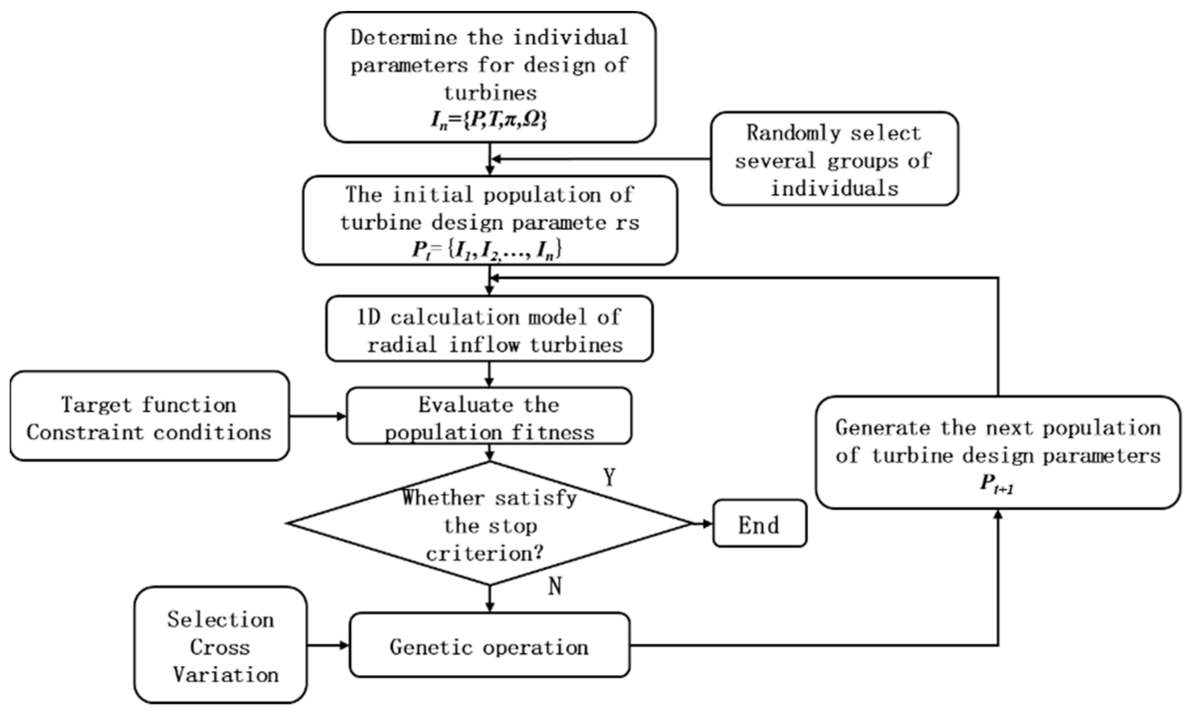
2.1. 1D Design

In this study, the radial inflow turbine is designed based on the 1D calculation model established by Aungier et al. [31]. The range of initial design parameters is determined according to the turbine design requirements, as shown in Table 1 [32]. During the optimization design process of the turbine, the maximization of turbine stage efficiency, η s t a g e , is taken as the optimization objective, and the genetic algorithm (GA) is applied to search the design parameters of the radial inflow turbine [33,34].
Equation (1) is applied to calculate the stage efficiency.
η s t a g e = f ( u - 1 , Ω , φ , ψ , α 1 , β 2 , D ¯ 2 ) = 2 u ¯ 1 [ φ c o s α 1 1 Ω D 2 ¯ 2 u ¯ 1 + D 2 ¯ ψ c o s β 2 Ω + φ 2 ( 1 Ω ) + D 2 ¯ 2 u ¯ 1 2 2 u ¯ 1 φ c o s α 1 1 Ω ]
The optimization process of the 1D design genetic algorithm is shown in Figure 1. The fitness function is the target function of turbine design, namely MaxF = Max η s t a g e = Max | f ( u - 1 , Ω , φ , ψ , α 1 , β 2 , D ¯ 2 ) | (Table 2 shows the constraint conditions of the relevant parameters). The initial design parameters of the radial inflow turbines in Table 1 are taken as the individual parameters. From the optimization of the GA, the values the optimal results are shown in Table 3.

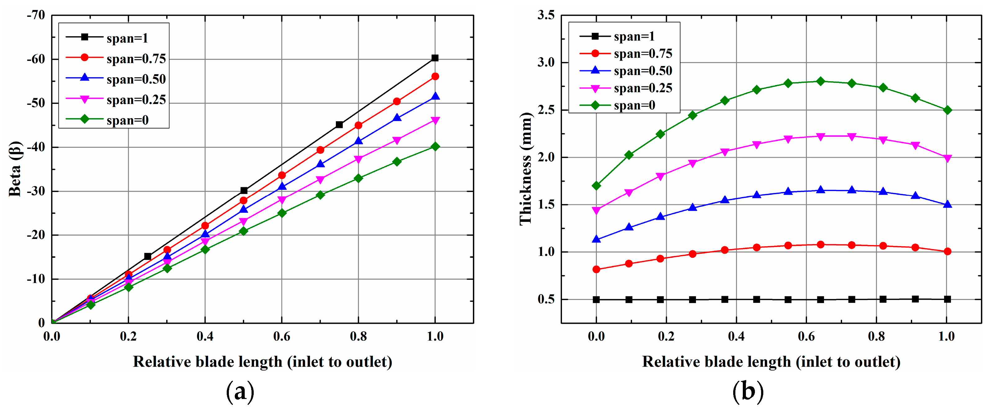
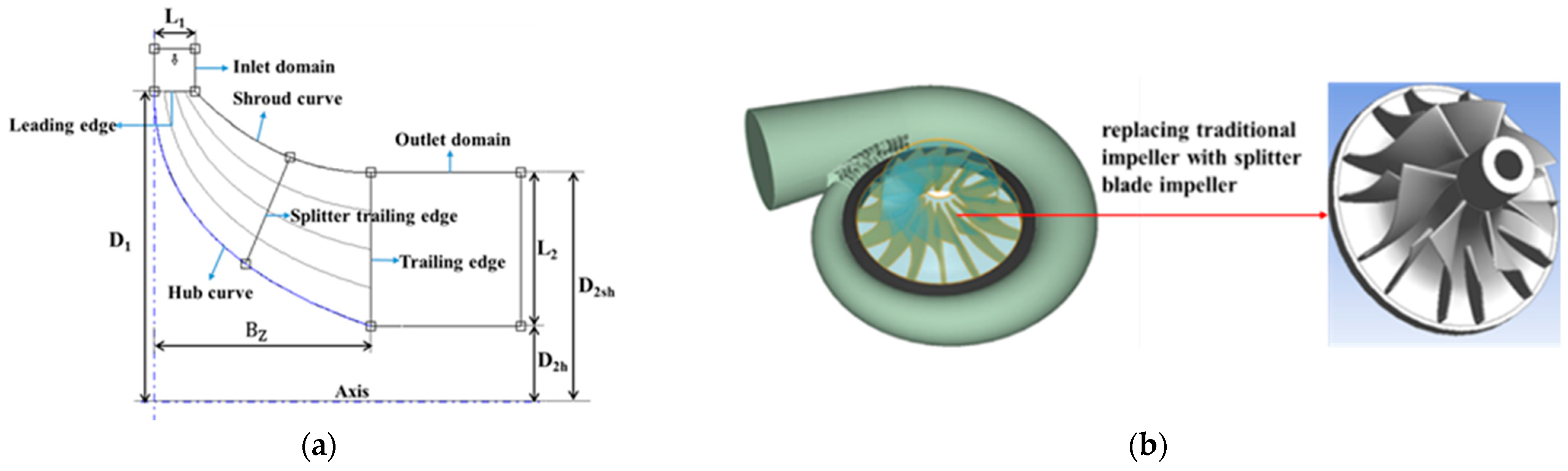
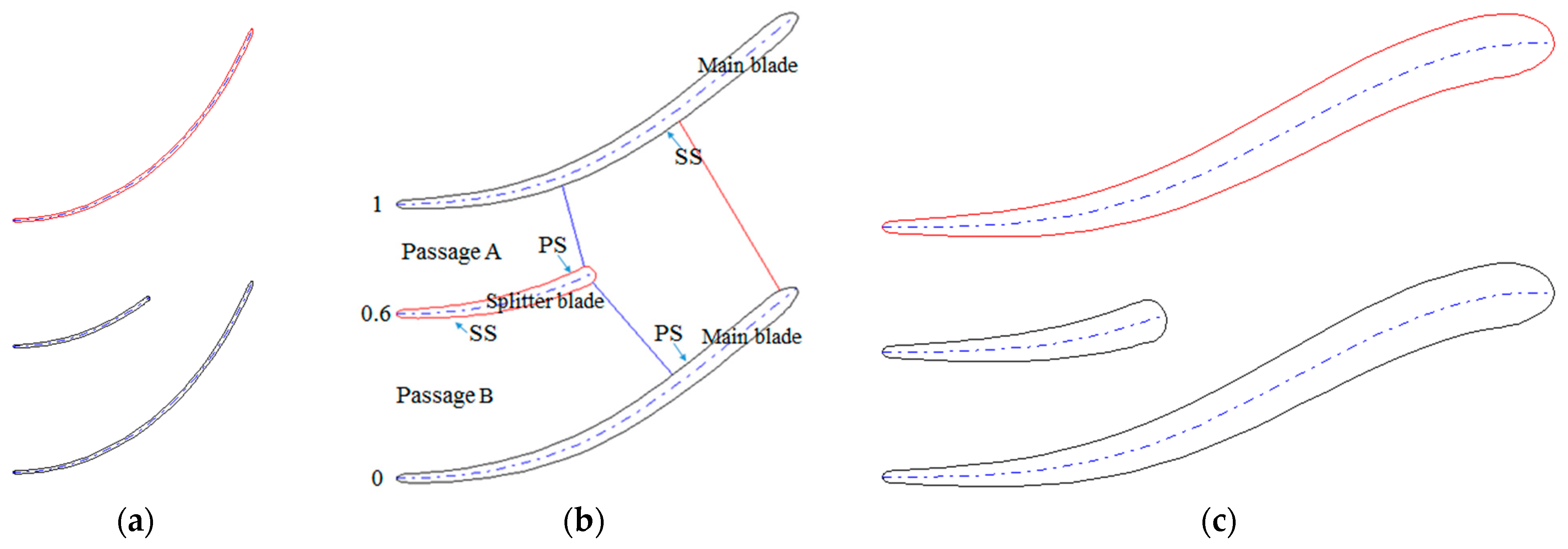
2.2. Geometric Structure

Considering the limitations of the calculation resources and calculation period, only the rotor impeller was selected as the research subject to simplify the calculation, and the volute and stator were not considered. The rotor impeller with splitter blades was applied to 10 kW ORC radial inflow turbines in this study. The meridian plane and geometric structure of the impeller are shown in Figure 2 and the parameters on the meridian surface were consistent with the design parameters in Table 3. The splitter blade can be obtained by cutting the main blades such that they have the same blade profile as the main blade. The blades can be modeled by radial overlap of the cross section in different directions of blade height through ANSYS®-BladeGen. The cross sections with relative blade heights of 0, 0.5, and 1 are shown in Figure 3, and the design parameters are shown in Figure 4. The splitter blade is located between the main blades, and the meridian length is smaller than that of the main blades.
According to ANSYS®-BladeGen’s definition of splitter blades, the circumferential offset of the blades, Soffset, refers to the ratio between the circumferential distance from the suction surface (SS) of the splitter blades to the pressure surface (PS) of the main blades and the circumferential distance between the two main blades. The circumferential offset of the splitter blades shown in Figure 3 is 0.6. The meridian length of the splitter blades, Ls, refers to the relative length of the splitter blades on the meridian plane, that is, the ratio of the meridian length of the splitter blades to the meridian length of the main blades. As shown in Figure 3, the passage between the SS of the main blades and the PS of the splitter blades is herein called passage A, the passage between the SS of the splitter blades and the PS of the main blades is passage B. In order to study the influence of the circumferential position and length of the splitter blades on turbine performance, 0.35, 0.40, 0.50, 0.60, and 0.65 were selected as the circumferential offsets of the splitter blades. Furthermore, given that the length of the splitter blades is limited by passage obstruction and blade surface friction loss, 60%, 70%, 80%, and 90% of the main blade length were selected for the splitter blade lengths, and the impeller schemes are shown in Table 4.

2.3. Performance Index

For the convenience of evaluating the performance of impellers, two performance indexes, total pressure loss coefficient, and energy loss coefficient, are introduced in this paper.
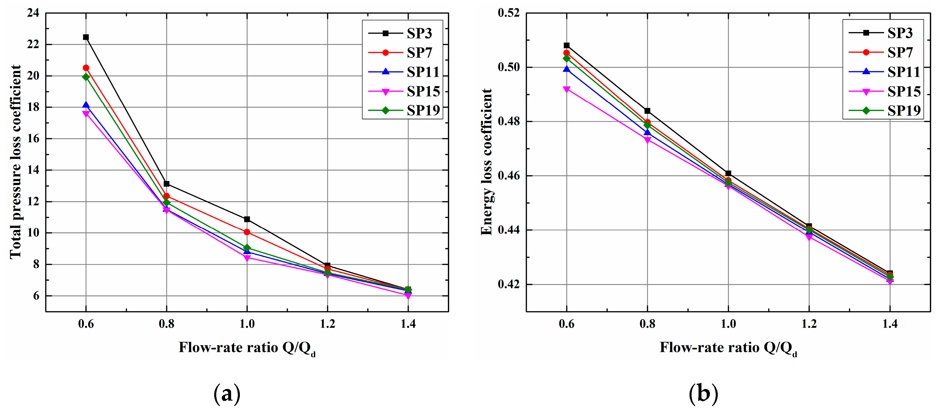
  • Total pressure loss coefficient.
The total pressure loss coefficient is the portion of pressure loss in the stator or rotor. It can be written as:
ω b ˜ = P 1 * P 2 * P 2 * P 2
where P 1 * is the total pressure at impeller inlet, MPa; P 2 * . is the total pressure at the impeller outlet, MPa; and P 2 . is the backpressure at the impeller outlet, MPa.
2.
Energy loss coefficient.
The ratio of the rotor blade loss to the stagnation ideal enthalpy drop inside the rotor blade Δ h b * . is defined as the energy loss coefficient of the impeller. It can be written as:
ξ b = Δ h b ζ Δ h b * = 1 ψ 2 .  
where Δ h b ζ is the rotor blade loss, kJ/kg;   Δ h b * is the stagnation ideal enthalpy drop inside the rotor blade, kJ/kg; and   ψ   is the velocity coefficient of the rotor blade.

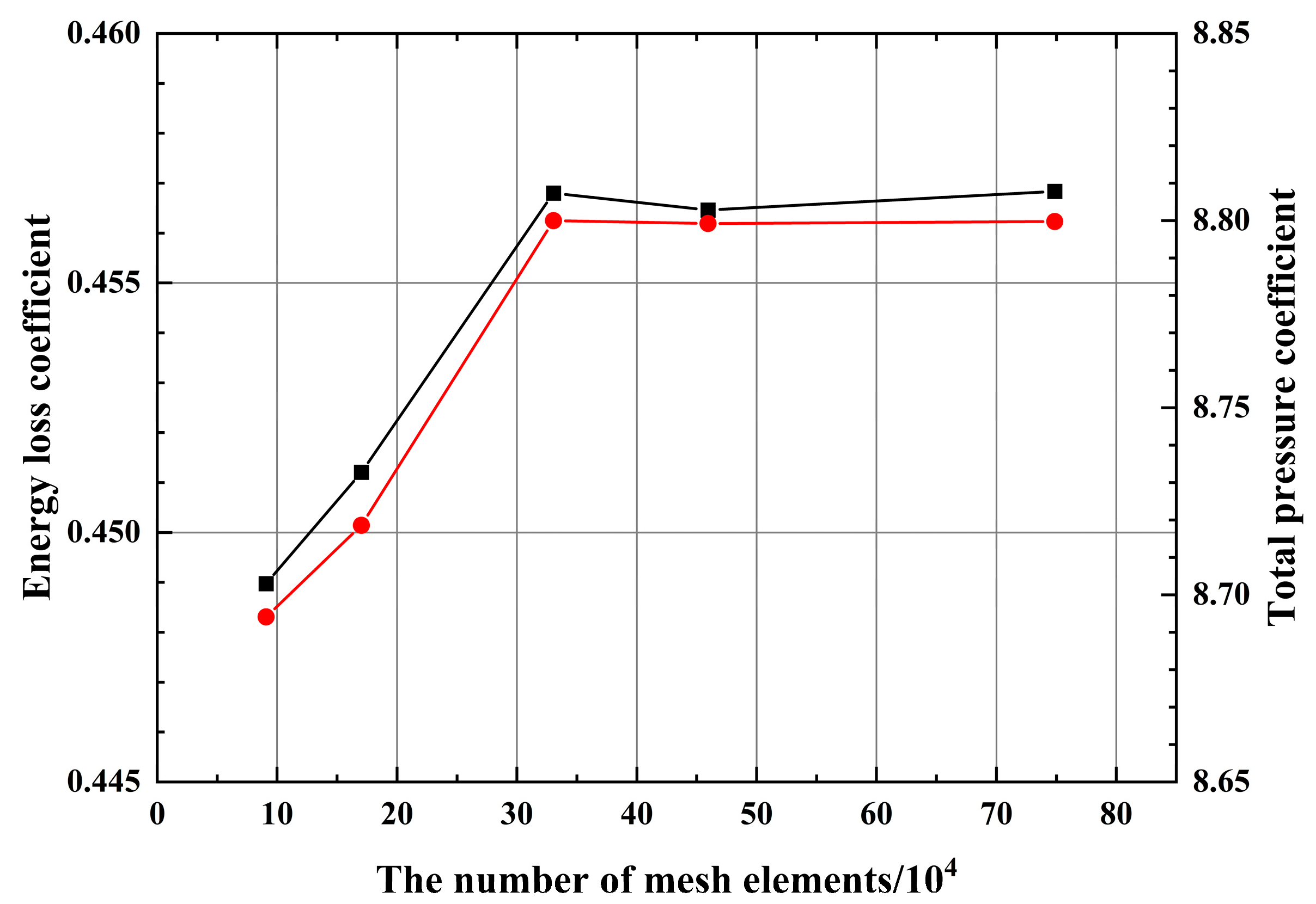
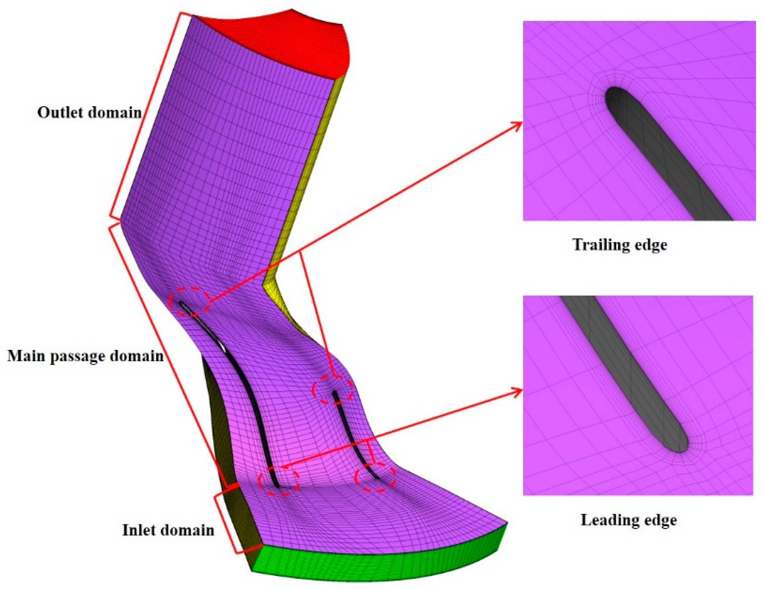
2.4. Grid and Boundary Conditions

A single passage of the impeller was selected as the simulation object due to the cyclic periodicity of the impeller. The structural grid of the impeller passage was meshed through the turbo-grid. To guarantee the convergence of the calculation process, extension of the inlet and outlet was conducted appropriately for the impeller. The grid consists of three parts, namely the inlet domain, main passage domain, and outlet domain, which are available for data exchange through the interface. As a single passage of the impeller was selected as the simulation object, the corresponding rotating periodic surfaces were set at both sides of passage. It can be determined from the grid independence test that there were 330,000 impeller grids in this study, which is the minimum grid number that satisfies the calculation accuracy. The grid independence test is shown in Figure 5 and the passage grid is shown in Figure 6.
In this study, CFD calculation was conducted on the impeller passage through Fluent® 15.0. The Spalart–Allmaras model was applied as the turbulence model and the SIMPLEC algorithm was applied to solve the pressure–velocity coupling flow field. In consideration of the thermophysical properties, environmental properties, and safety of the working fluid, R245fa was selected, and the physical properties can be obtained from the NIST REFPROP9.0 database, as shown in Table 5. According to the impeller design parameters in Table 3, the mass flow inlet was applied as the impeller inlet. The mass flow rate of the working fluid in single passage was 0.1 kg/s and the inlet temperature was 370 K. The impeller outlet was set as the pressure outlet and the outlet backpressure was 80,675 Pa. The rotational speed was 30,000 rpm and the rotational periodic boundary was set at both sides of passage. The blades and impeller hub were set as the wall boundary, which moved with the domains. The second-order upwind scheme was applied to energy and momentum equations as a discrete scheme to guarantee the calculation accuracy. When the residual of each parameter was lower than 10−5, it was regarded as the calculation convergence.

3. Results and Discussion

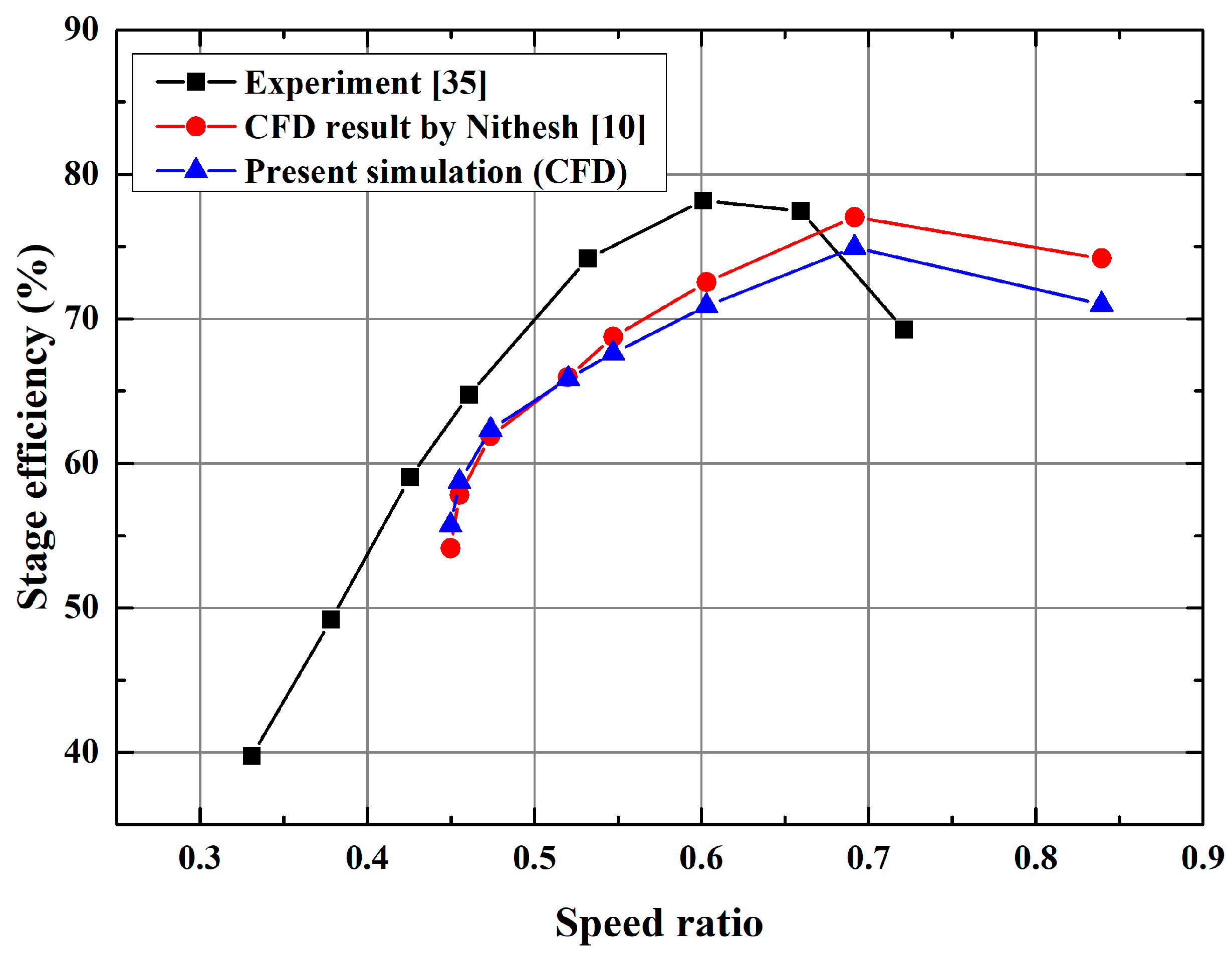
3.1. The Validation of the Numerical Approach

In this study, the numerical prediction was validated by the experimental data from reference [35], wherein the radial turbine operating with R12 refrigerant as a working fluid was experimentally investigated. In order to further ensure the credibility of the model, the simulation results of this radial turbine, produced by Nithesh et al. [3], were selected for comparison. The specific design parameter of the turbine refers to the literature [34], and the operation conditions are: mass flowrate of 26.4 kg/s, rotational speed of 3150 rpm, inlet temperature of 85 °C, and inlet and outlet pressures of 6.05 kg/cm2 and 1.79 kg/cm2, respectively. The performance curve is presented in Figure 7, and a comparison shows that the results of this study agree with the experimental data and the simulation conducted by Nithesh et al. Thus, it can be concluded that the numerical approach in this study has a high credibility.

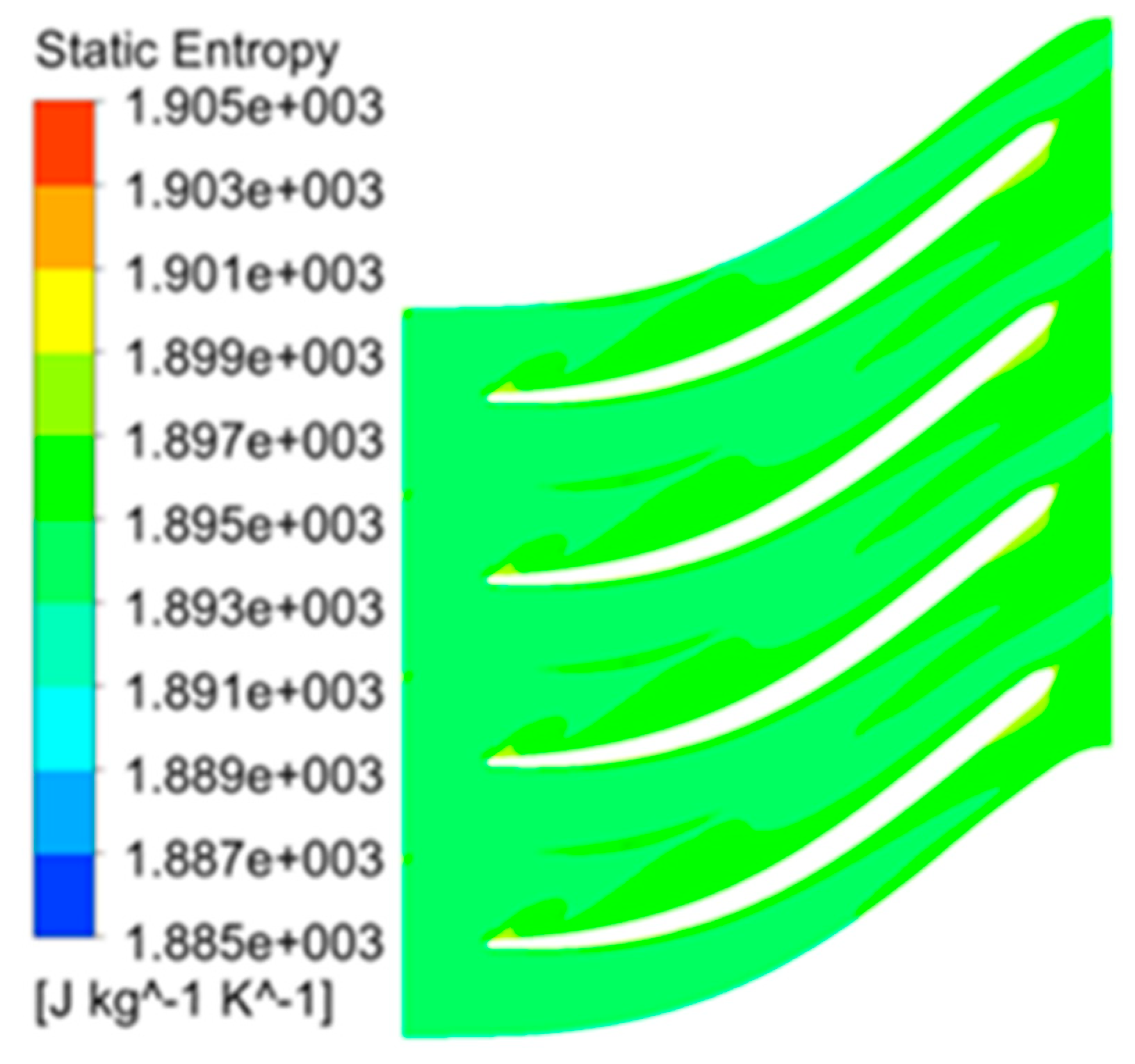
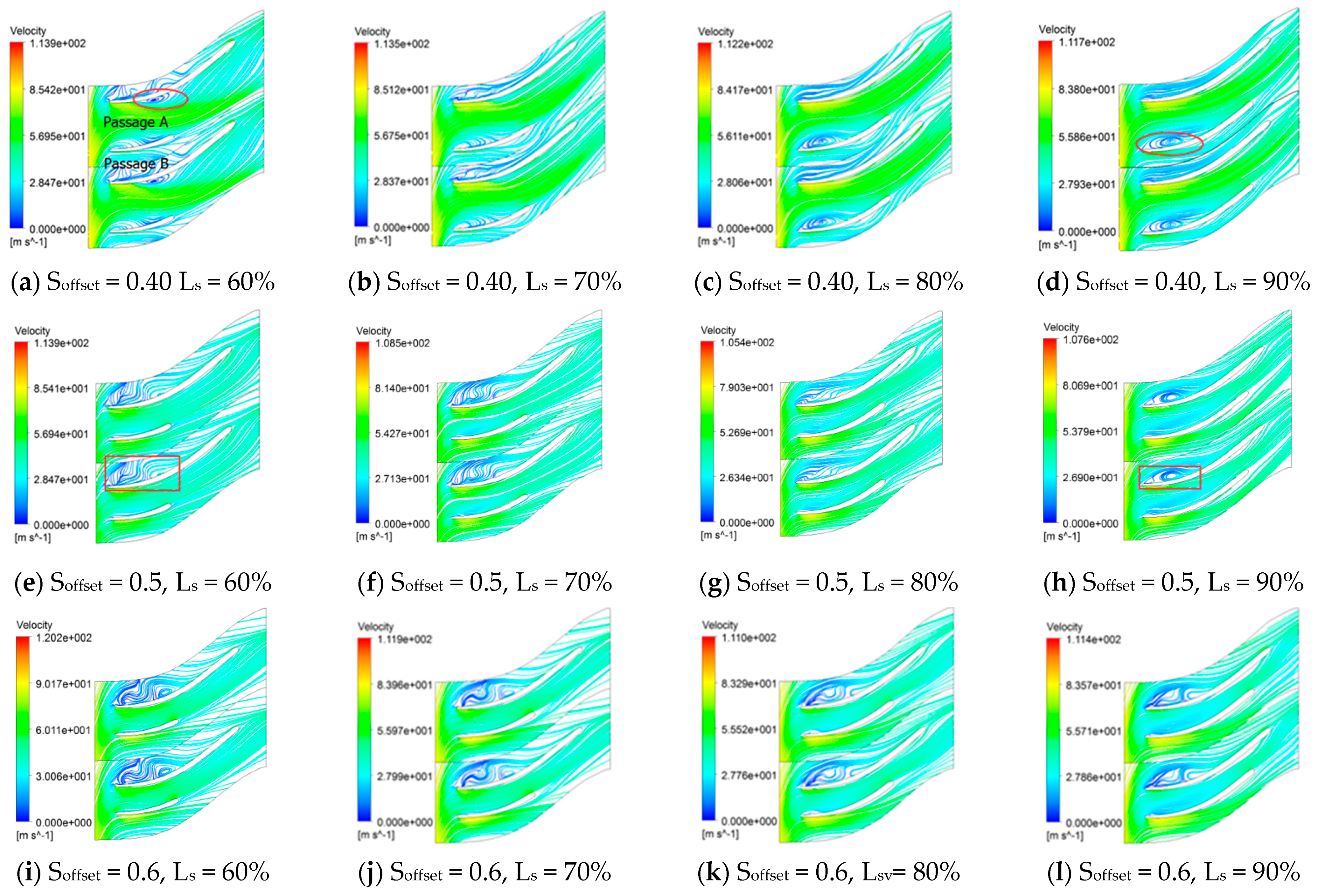
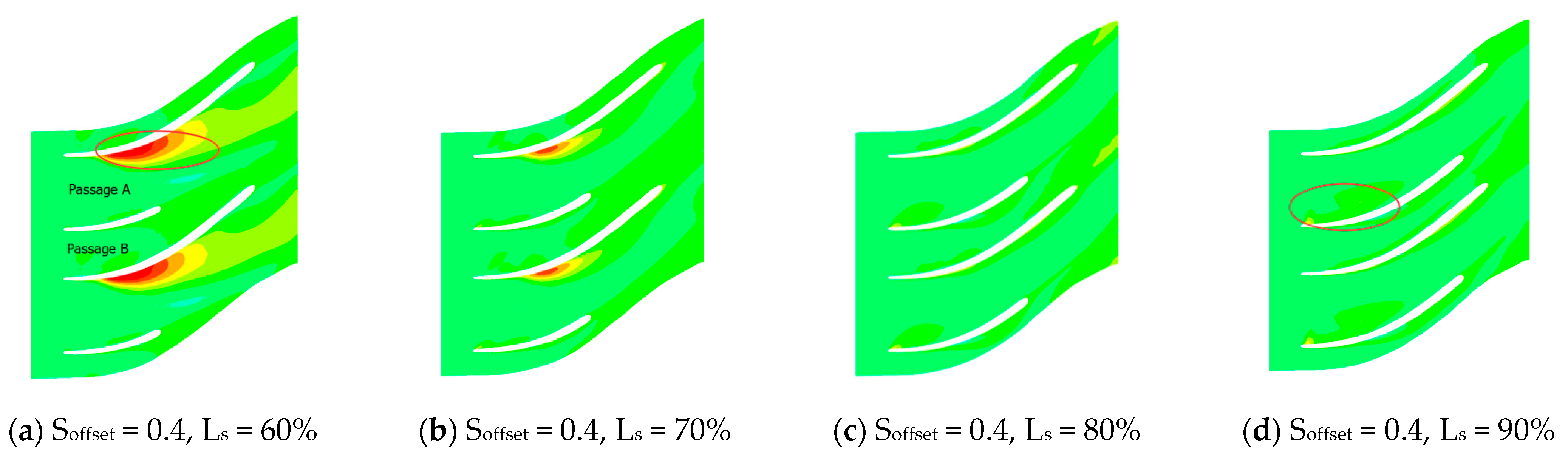
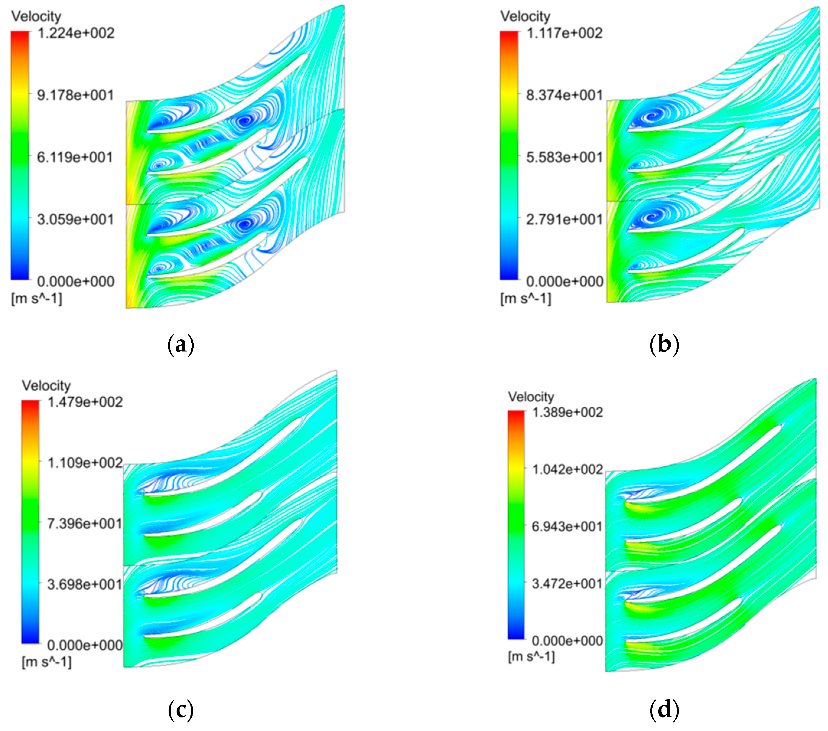
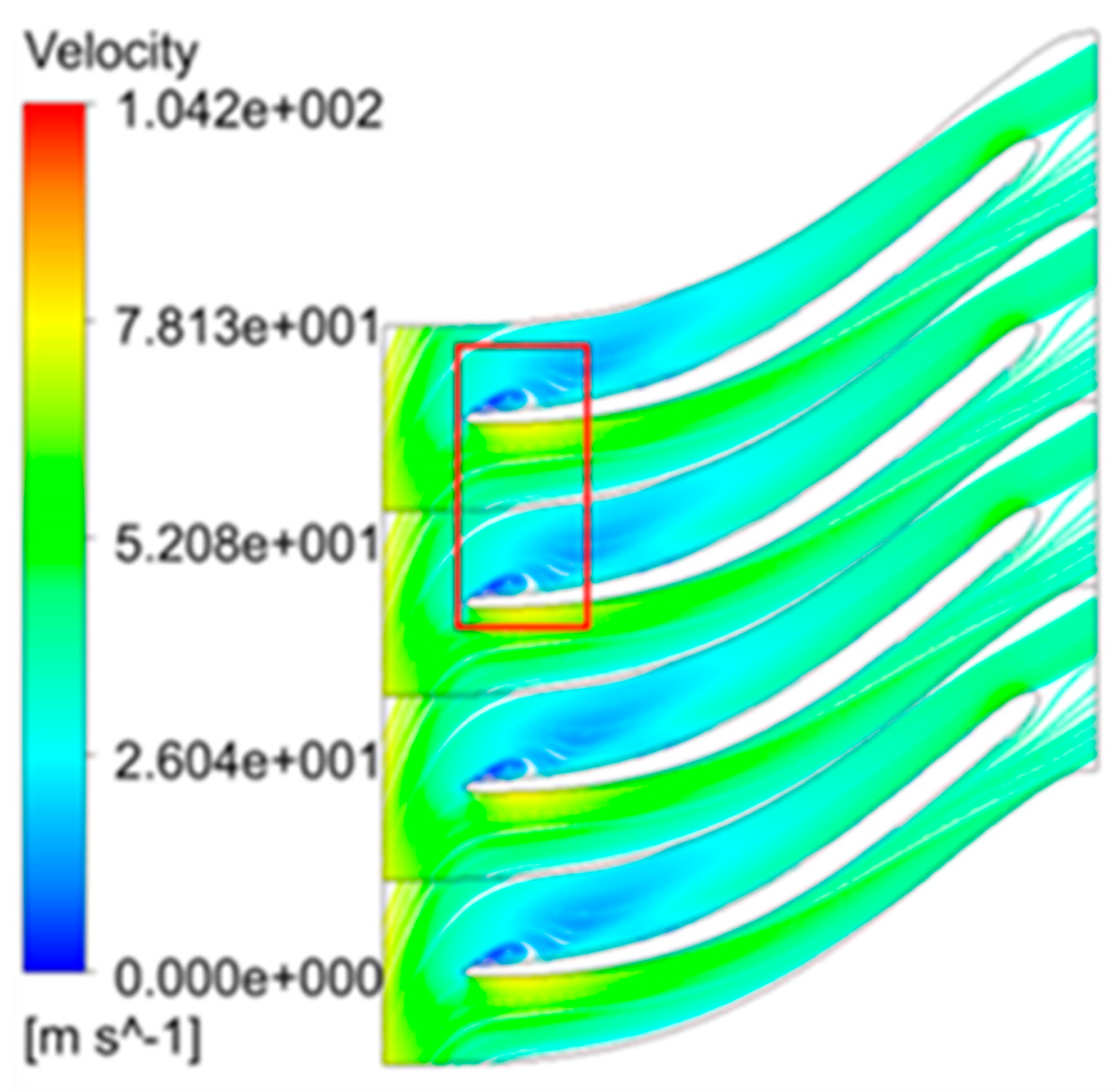
3.2. Influence of Splitter Blades on Flow Field of Impeller Passage

The numerical simulation was conducted on the 20 impeller schemes, and the streamline distribution and pressure distribution inside the passage of each scheme were obtained. For the reason that the flow field distribution under offset 0.35 is similar to the situations under offset 0.40, and the flow field distribution under offset 0.65 is similar to the situations under offset 0.6. Thus, only the situations of Soffset = 0.4, 0.5, and 0.6 were adopted in this study and the results of each blade length scheme were analyzed and are demonstrated. The flow field distribution at 50% span is shown in Figure 8. When Soffset = 0.4 and Ls is 60%, the splitter blades are shortest, as shown in Figure 8a, and the effect of the passage on the working fluid is weak, leading to a worse flow state inside the passage. As there is greater inverse pressure gradients on the SS of the main blades, there are large-scale vortex domains on the SS of the main blades inside passage A, namely the area marked by an ellipse in the figures. The vortex domain is located at the outlet of passage A, which not only obstructs the passage but also increases the energy loss inside the passage. With the increase in splitter length, as shown in Figure 8b–d, passages A and B lengthen, the diversion effects of the passage are enhanced, the flow separation inside passage B is inhibited, and the flow field gradually becomes uniform. Near the SS of the main blades inside passage A, the inverse pressure gradient gradually decreases, leading to a great improvement in the flow state. However, the increase in splitter length will enlarge the transverse pressure gradient at the inlet of passage A and cause the boundary layer of the blade surface to be more vulnerable to lateral transfer. Thus, the vortex domain at the LE of the splitter blades will gradually expand, and it can also result in obstruction and increase the energy losses. Moreover, the increase in splitter length will enlarge the friction losses near the blades. Therefore, in the design of the splitter impeller, an appropriate length needs to be selected for the splitter blades.
It can be found from Figure 8 that when Soffset = 0.5 and 0.6, the splitter blades can also improve the flow field distribution inside the passages and the effects of the blade length are basically the same as those of Soffset = 0.4. The circumferential offset can influence the distribution inside the passages. When the circumferential offset is small, Soffset = 0.4. As shown in Figure 8a, the splitter blades are relatively far from the SS of the main blades and the transverse pitch of passage A is relatively large. The fluid is slightly constrained by the blades and turbulent flow mainly occurs in passage A. Furthermore, the smaller the circumferential offset, the larger the transverse pitch of passage A and the more apparent the turbulent flow inside the passages. When the circumferential offset increases, Soffset = 0.5 or 0.6, as shown in the figures, and the splitter blades approximate to the SS of the main blades and the turbulent flow inside the passages is transferred. At that time, passage A becomes narrower and the blades’ control of the fluid is enhanced, and the flow separation inside the passages is inhibited and the streamline distribution becomes uniform. With the increase in the gap between the splitter blades and the PS of the main blades, the blades’ constraints on the fluid inside passage B weaken and the fluid inertia exerts an effect on flow inside the passages. The turbulent flow inside the passages will continuously deteriorate with increasing offset. When the fluid enters passage B, separation immediately appears at the LE of the main blades and a larger-scale vortex domain appears at the passage inlet. The vortexes here also result in energy consumption, which negatively impacts the impeller performance. Therefore, when selecting the circumferential offset of splitter blades, the optimal flow domain of passages A and B must be guaranteed to ensure a better flow state inside passages A and B.

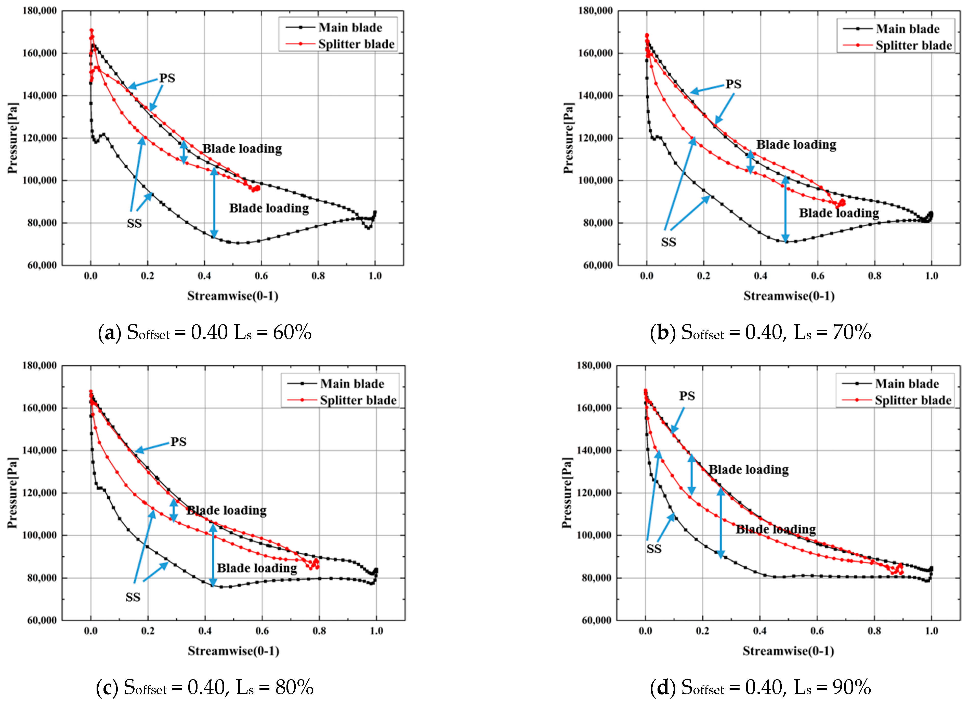
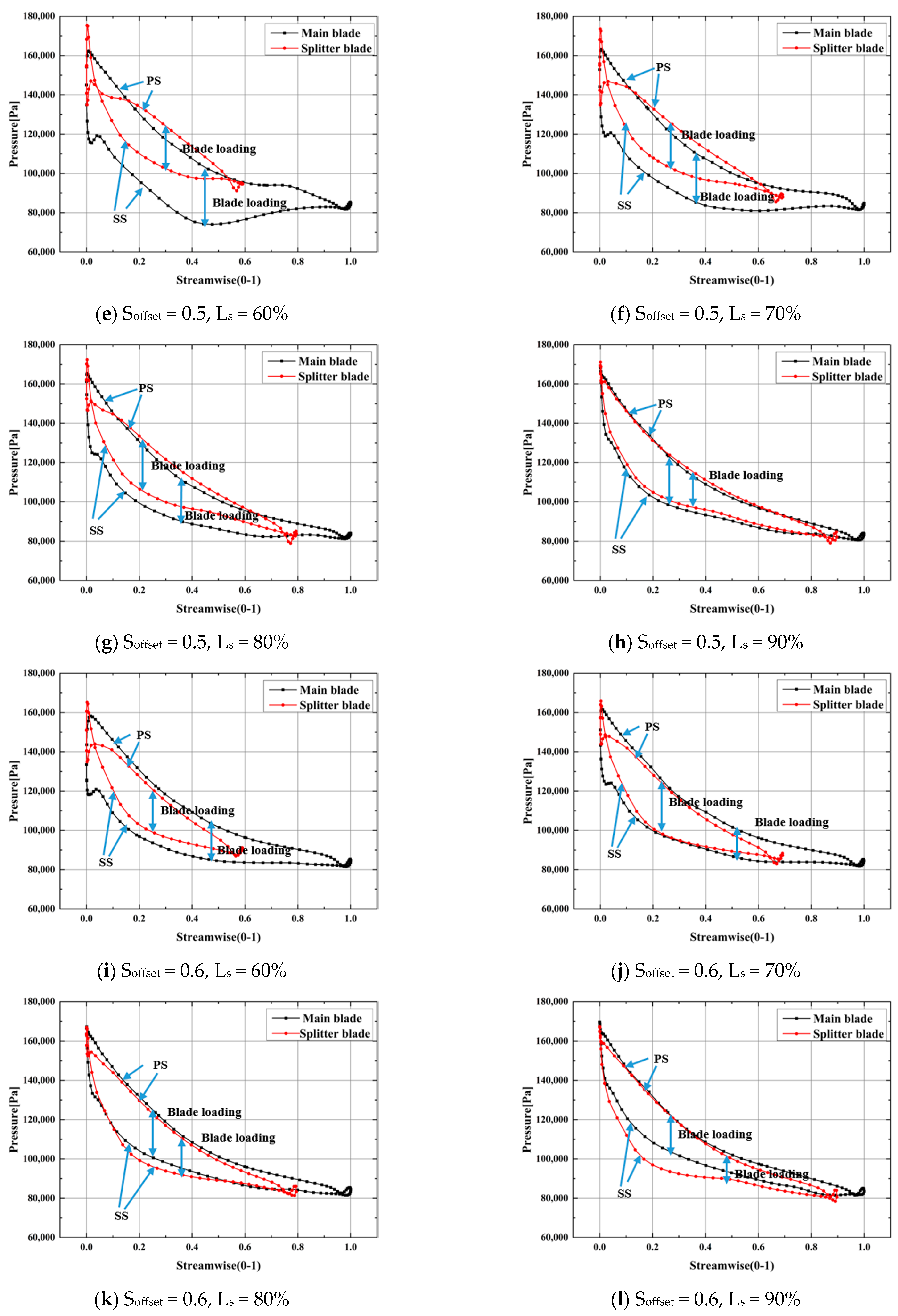
3.3. Influence of Splitter Blades on Impeller Load Distribution

Compared with the conventional impeller, splitter blades can share the load of the main blades and reduce the strength requirement. The load distribution diagram of blades is shown in Figure 9, where blade loading refers to the pressure difference between the PS and SS of each blade. It can be observed from the figures that, under the same offset, when Ls = 60%, due to a lack of flow diversion of the blades, the splitter blades’ ability to shoulder the load is weaker, and the load is mainly concentrated on the main blades. With the increase in blade length, the flow separation inside the passages is inhibited and the load on the splitter blades increases. Meanwhile, the load of the main blades also decreases. In addition, when the splitter blades are shorter, there will be a larger inverse pressure gradient on the SS of the main blades and the existence of inverse pressure promotes the flow separation and vortex domains on walls. With the increase in splitter blade length, the inverse pressure gradient near the SS of the main blade eases, and the flow state inside the passages improves. Due to existence of splitter blades, the pressure and velocity distributions inside passages A and B are not completely the same. When the working fluid flows out of the two passages, mixed flow occurs at the back passages. The pressure fluctuation, as shown in Figure 9, will occur at the TE of the splitter blades, where the mixed flow will lead to certain energy losses and influence the impeller performance.
Under the small offset, such as the case of Soffset = 0.4, as shown in Figure 9, the load shared by the splitter blades is relatively small and the load on the main blades is far greater than that on the splitter blades, which harms the working capacity and structural strength of the impeller. In addition, as mentioned above, the transverse distance of passage A is larger and the transverse pressure difference inside the passages refers to the pressure difference between the SS of the main blades and the PS of the splitter blades. As the pressure distribution on the PS of splitter blades is similar to that on the SS of the main blades, leading to a greater transverse pressure difference inside the passages, the pressure difference makes the fluid more vulnerable to transverse transfer and promotes the formation of wall separation flow inside passages. When the length of the splitter blades remains the same, increasing the circumferential offset, as shown in Figure 9, where Soffset = 0.5 and 0.6, enhances the splitter blades’ ability to share the load. The load distribution among blades becomes more uniform and the transverse pressure difference inside passage A correspondingly decreases. Moreover, the inverse pressure gradient near the SS of the main blades decreases with the increase in offset. It can be seen from Figure 8, where Soffset = 0.6, that the inverse pressure on the SS of longer blades in each blade length scheme has basically disappeared, as did the vortex area on the SS of the main blades. Thus, the flow state inside passage A improved greatly.

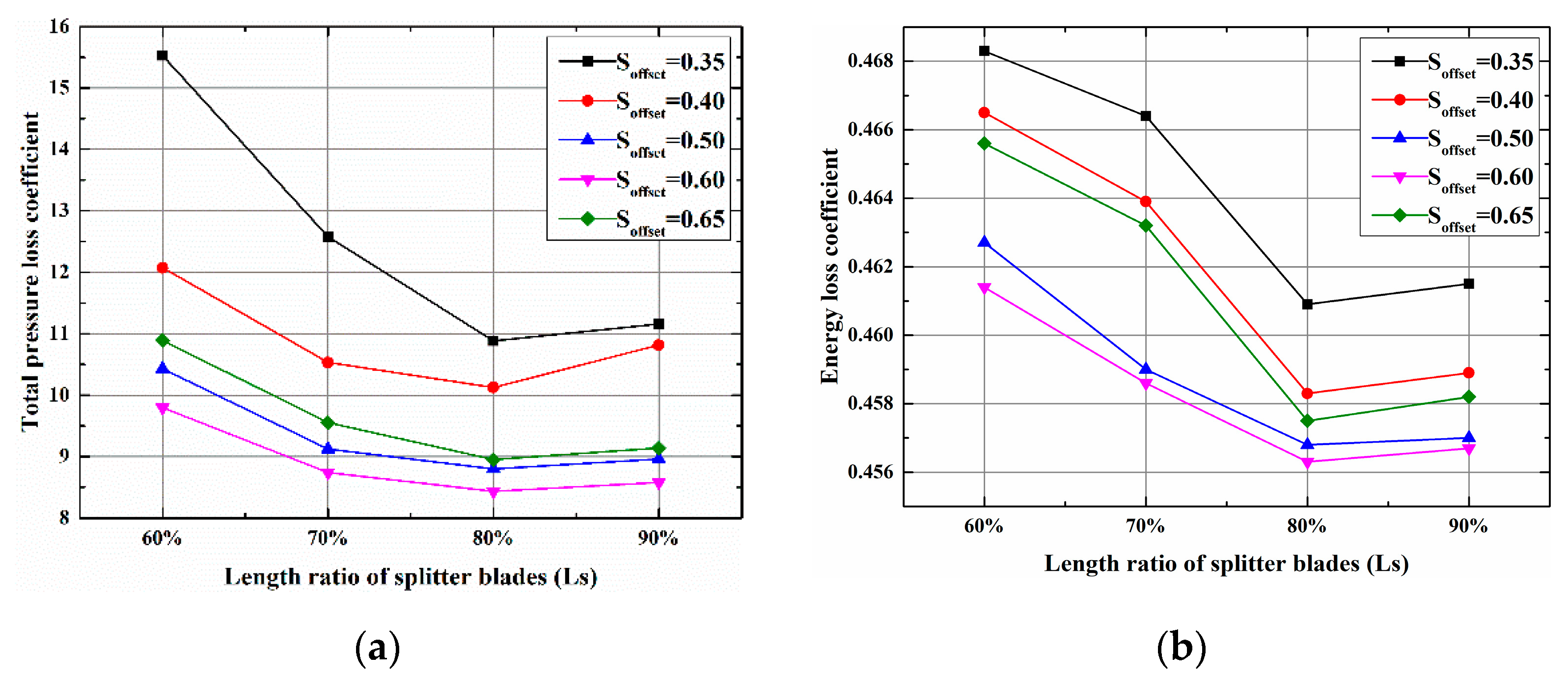
3.4. Influence of Splitter Blades on Flow Losses Inside the Passages

The contours of entropy distribution inside the passages are shown in Figure 10. The greater the entropy production, the greater the losses and the worse the impeller performance. When Soffset = 0.4 and Ls = 60%, as shown in Figure 10a, the static entropy inside passage A is clearly higher than that inside passage B. On account of the existence of vortex areas inside passage A, a local high entropy area that diffuses into the middle of the passages in radiation occurs on the blade surface, leading to obstruction at the outlet of passage A and deviation of fluid to the outlet of passage B. Therefore, the value of static entropy at the back of passage B improves. Additionally, due to the diversion effect at the inlet of passage B, the turbulent flow at the inlet produces a slightly higher local static entropy inside the passage than that in the surrounding environment. However, the static entropy here is far smaller than that in the vortex area in passage A. As the splitter blade length increases, as shown in Figure 10b–d, the diversion effect of the passages increases and the high-entropy area in passage A gradually decreases. The influence of the vortex area on passage A gradually decreases and finally disappears, and the flow state inside the passages gradually improves. With the continuous increase in blade length, as mentioned above, the transverse pressure difference at the inlet of passage A increases, which causes the fluid to be more vulnerable to transverse transfer. The turbulent flow at the inlet makes the local high-entropy area at the LE of the splitter blades diffuse into the passages. The losses here are mainly located at the inlet of passage A and the impeller outlet, but the losses are far smaller than those in the high-entropy area, as shown by Figure 10a.
It can be seen from Figure 10 that, under the same length of splitter blades, when the offset increases, the static entropy distribution inside the passages changes along with the changes in the flow field. The high-entropy area triggered by the vortex inside passage A gradually decreases, but the effect of the transverse pressure difference inside the passages remains. When the splitter blades are longer, there is still the area with higher entropy on the LE of the splitter blades of passage A, as shown in Figure 10h. Nevertheless, with the increase in the transverse distance of passage B, the aggravated turbulent flow inside the passages increases the static entropy at the inlet and the static entropy area gradually increases with the increase in offset, as shown in Figure 10e,f. When Soffset = 0.6, the high-entropy area in passage B becomes quite obvious, as shown by Figure 10i,j.
However, the losses here are still smaller than those in the high-entropy area in passage A when Soffset = 0.4. At that time, there is no area with higher entropy production inside passage A and the influence of the transverse pressure difference on the passages basically disappears with the narrowing of passage A. When Soffset = 0.6, the trailing loss after the splitter blades becomes very obvious, especially in the cases of shorter splitter blades, as indicated by the ellipse in Figure 10i. Thus, there remains optimization space for the splitter blades. Based on the comprehensive consideration of the static entropy distribution inside the passages in each impeller scheme, it is necessary to guarantee the reasonable static entropy distribution inside passages A and B when selecting the offset. According to the distribution of the contour above, it can be judged that the optimal offset for splitter blades is in the interval of 0.5–0.6.
Through analysis of the simulation results, the performance parameter curves of each splitter blade impeller were obtained, as shown in Figure 11. The changing trends of the total pressure loss and energy loss coefficients are basically the same. Under each offset scheme, when the splitter blades are the shortest, Ls = 60%, the passage is the shortest with a weaker diversion effect, there is a worse flow state inside passages, and the most significant flow separation. Thus, the largest total pressure loss coefficient and energy loss coefficient appear. With the increase in splitter length, the passages grow, which inhibits the flow separation on the blade surface, and the flow is improved with the increase in splitter blades. Thus, the impeller performance is improved. With the further increase in splitter length, the flow separation on the LE of the splitter blades of passage A becomes aggravated and the friction losses on the blade surface also increase. Furthermore, the obstruction at the impeller outlet will deteriorate with the reduction in the flow area at the outlet. Thus, the impeller will become worse with further increases in the splitter length. The total pressure loss coefficient and energy loss coefficient will show the changing trend of increasing after decreasing, as shown in Figure 11.
It can also be seen from Figure 11 that, when Ls remains the same, the relationship between the two index parameters is generally summarized as 0.35 > 0.4 > 0.65 > 0.5 > 0.6. Under the small offset, namely Soffset = 0.35 or 0.4, there is a local large-scale vortex area in the SS of the main blades inside passage A, where the static entropy is far greater than that of other passage parts and the energy loss inside the impeller is greater. Therefore, compared to other offset situations, there are always a greater total pressure loss coefficient and energy loss coefficient in the impeller. When Soffset = 0.65, due to the excessively large offset, compared to the offset of 0.5 and 0.6, the circumferential distance of passage B increases and the passages’ constraint effect on the working fluid weakens. At that time, the inertia of the working fluid exerts certain effects on the flow and the flow inside passage B is more turbulent, leading to greater losses inside passages than those of offsets of 0.5 and 0.6. Thus, the total pressure loss coefficient and energy loss coefficient are large and the impeller performance is worse. However, losses caused by the turbulent flow here are much smaller than those in the large-scale vortex area at the outlet of passage A under a small offset. Therefore, when the lengths of the splitter blades are the same, the impeller performance is better than that under the offsets of 0.35 and 0.4, but worse than that under the offsets of 0.5 and 0.6.
It can be concluded from the analysis that, under each offset circumstance, the optimal length of the splitter blades is about 80% of the length of the main blades and the optimal offset is between 0.5 and 0.6. In the optimal design of the ORC radial inflow turbine considered in this study, the splitter blade offset is about 0.6 and the blade length is 80% of the main blade length.

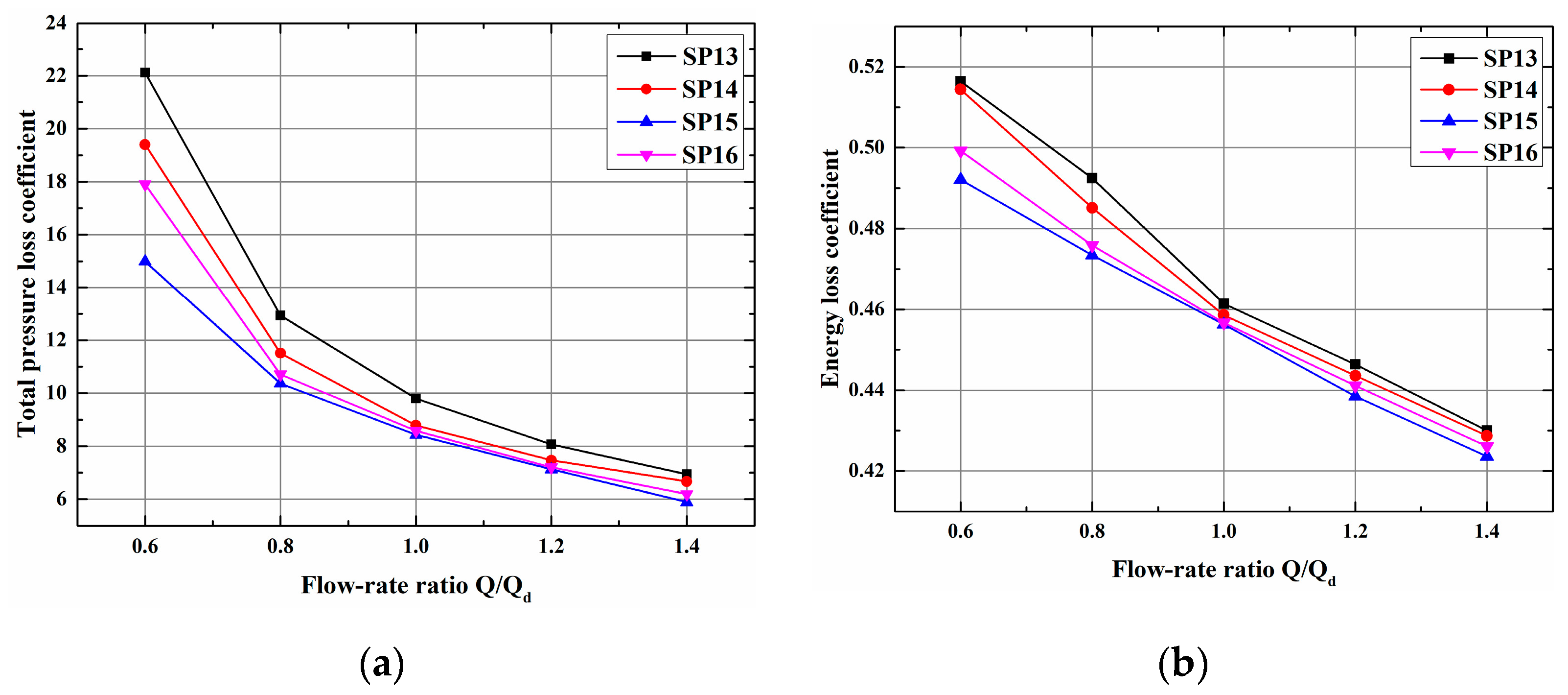
3.5. Performance Comparison of Splitter Impellers under Off-Design Conditions

The aforementioned analysis is based on the design condition Qd = 0.7 kg/s, but the turbine performance varies under off-design conditions. Figure 12 shows the streamline distribution of scheme SP15 under different mass flow rates and, under a low flow rate, serious flow separations are found which give rise to apparent vortex distributions. Under the 0.6Qd condition, the inlets of passages A and B both have large-scale vortexes and, meanwhile, the outlet of passage A has an apparent vortex as well. With the rise in the flow rate, the flow condition improves and, under the 0.8Qd condition, the vortex area at the outlet of passage A vanishes while the vortex at both inlets still exists. When the flow rate is no less than the design condition, the vortex area in passage B vanishes while the vortex at the inlet of the passage turns into flow separation of LE when the area decreases. Variation in the flow rate can influence the number and area of the vortexes in the passage, which means the turbine performance will change under off-design conditions.
In order to study the performance change of the impeller under variable flow rates, this study simulated different schemes and compared their performance parameters. Considering the similarity of the calculation results under the above impeller schemes, only the impeller schemes SP13~SP16 at Soffset = 0.6 and the schemes SP3, SP7, SP11, SP15, and SP19 at Ls = 80% were chosen for the performance comparison. The relevant performance curves are shown in Figure 13 and Figure 14. The flow rates in the figure were taken as 0.6Qd, 0.8Qd, 1.0Qd, 1.2Qd, 1.4Qd. It can be seen from the curve that as the flow rate increases, both the energy and the pressure loss coefficient under each scheme decrease. The value differences of the energy and the pressure loss coefficient between the schemes gradually decrease. The performance index parameters tend to be consistent. Additionally, the performance of the impeller is continuously improved, which meets the trend of the streamline diagram. It can be concluded from the curve that under the same offset, the loss coefficient always satisfies SP15 < SP16 < SP14 < SP13; while under the same splitter length, the loss coefficient always satisfies SP15 < SP11 < SP19 < SP7 < SP3. Considering the similarity of the calculation results of the above schemes, the conclusion can be drawn that under the scheme SP15, with Soffset = 0.6 and the Ls = 80%, the splitter impeller still has the best performance.

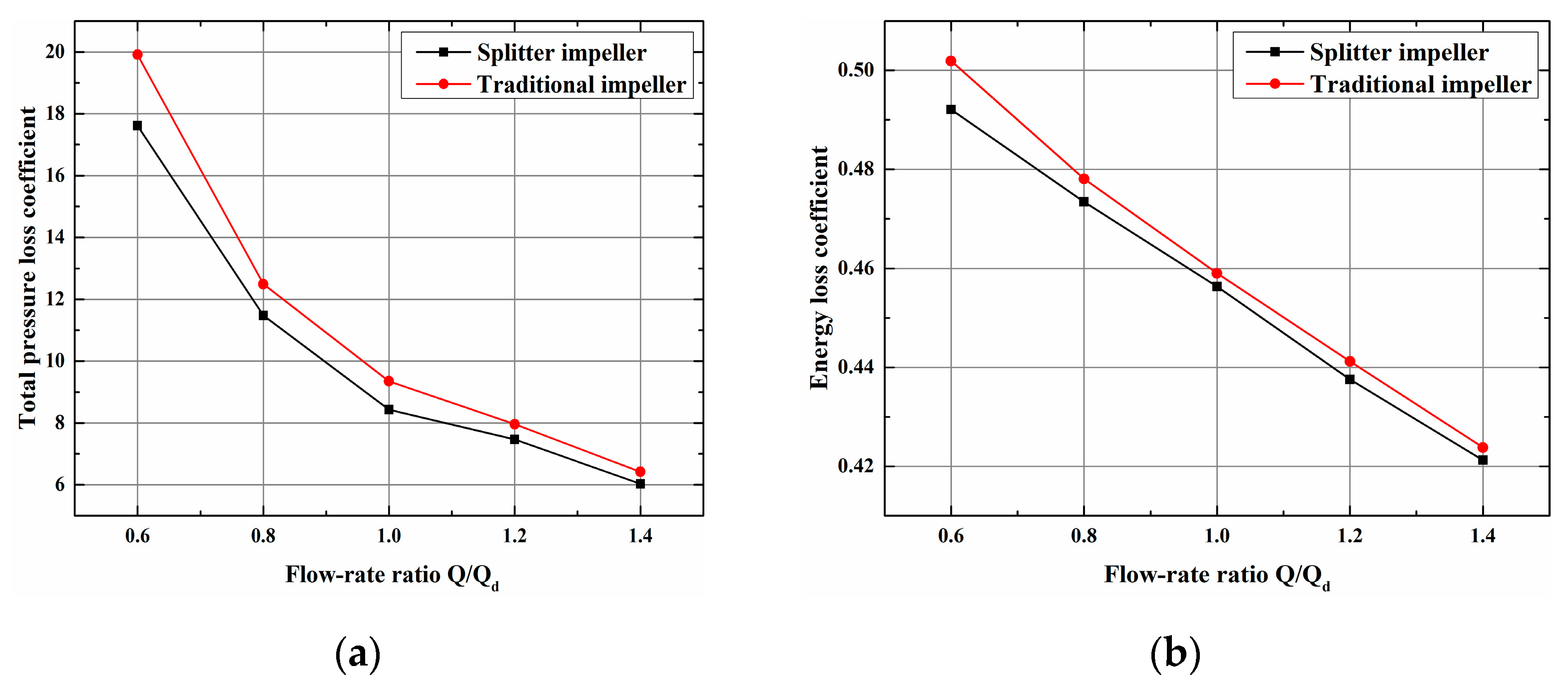
3.6. Performance Comparison between Splitter Impeller and Traditional Impeller

It can be concluded from the discussion above that the SP15 always has the best performance under the design condition and off-design condition. This study compared this scheme with the traditional impeller (Soffset = 0.5, Ls = 100%). The results of the streamline distribution and static entropy distribution in the passage of the traditional impeller under the design condition are shown in Figure 15 and Figure 16. In this case, passages A and B are evenly distributed and the flow conditions are the same. It can be seen from the above that as the splitter length increases, the lateral pressure difference at the LE increases, causing the separation of the boundary layer. Therefore, there is a small-range vortex zone on the LE of the blade PS, and the low-speed zone will diffuse toward the middle part of the passage. In the contour of entropy, the LE and the middle part of the passage have a local high-entropy area. There will be a blockage in the outlet of the passage due to the narrow surface section. Additionally, the friction loss on the surface of the blade will be intensified. Therefore, some local high-entropy areas will occur in the outlet of the impeller. The streamline distribution and static entropy distribution of the traditional impeller are inferior to the SP15.
Figure 17 shows the performance comparison curve between the splitter impeller SP15 and the traditional impeller. The change trend of the loss coefficients is similar to Figure 13 and Figure 14. The total pressure loss coefficient and the energy loss coefficient of the two impellers decrease with the increase in the flow rate, and the difference in the impeller loss coefficient gradually decreases. In addition, during the change process, the loss coefficient of the splitter impeller is always smaller than that of the traditional impeller, indicating that the impeller SP15 is superior to the traditional impeller in terms of impeller performance.

4. Conclusions

In this paper, a rotor impeller with splitter blades was proposed for the design and research of a 10 kW ORC radial inflow turbine. In order to analyze the influence of splitter blade length and offset on impeller performance, CFD calculation was conducted on impeller passages of 20 different schemes, and the different performance indexes were analyzed. The following conclusions are drawn:
  • The splitter length exerts apparent effects on the impeller performance and internal flow. When the splitter blades are shorter, it easily leads to inlet obstruction and energy dissipation. The splitter blades’ ability to share the load is weak. With the increase in splitter length, the flow field can be optimized. Furthermore, the splitter blades’ ability to share the load correspondingly improves. Nevertheless, with further increases in splitter length, the flow field deteriorated again, which decreased the impeller performance. Thus, the splitter blades cannot be excessively short or long. As for the calculation case in this study, when Ls is about 80%, the flow field distribution inside the impeller is optimum.
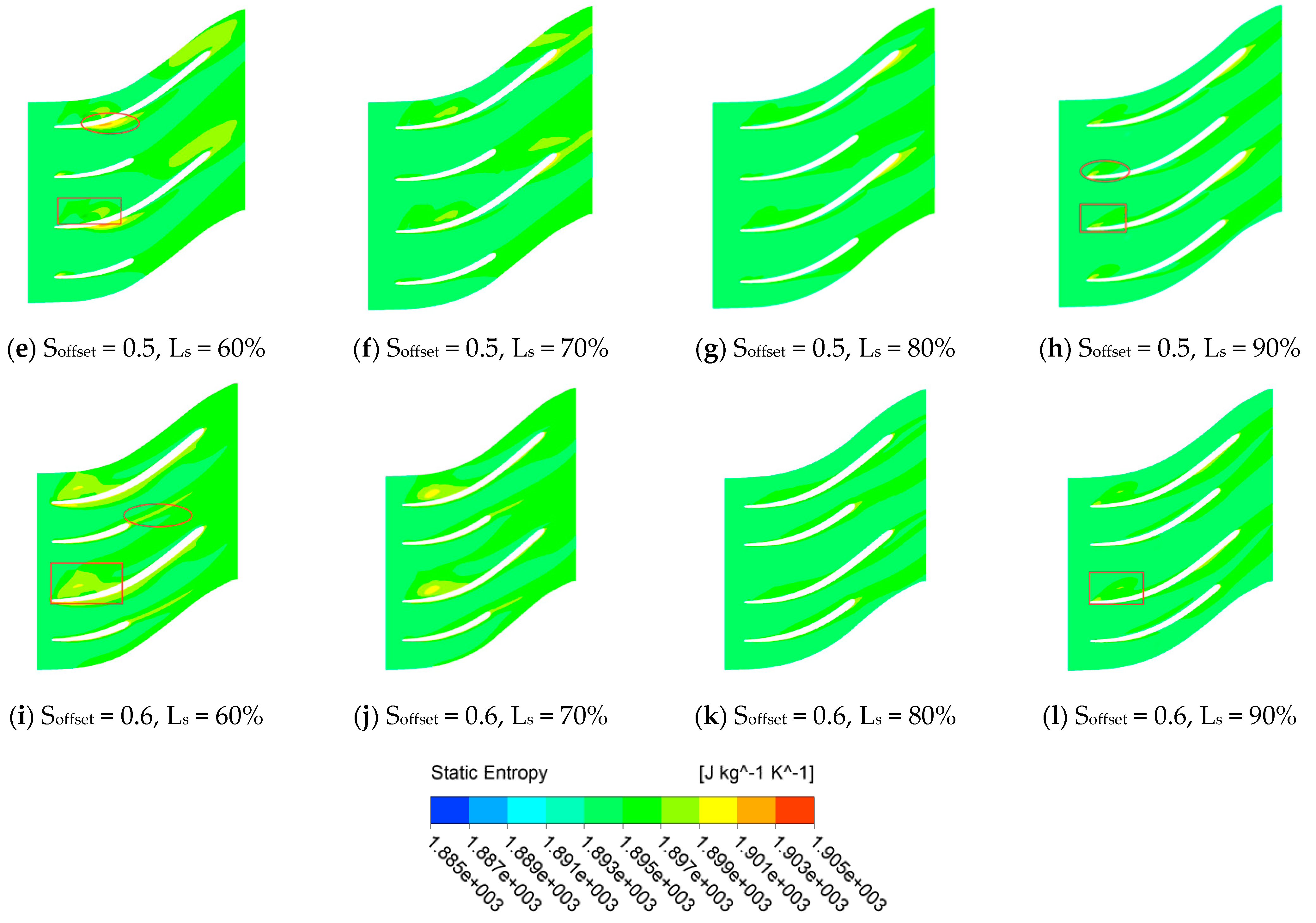
  • The circumferential distribution of blades also has a relatively large impact on the impeller performance and internal flow. The circumferential offset influences the distribution of the passage, and the differences in passage distribution lead to different flow states inside the passages and greater differences in their aerodynamic characteristics. With comprehensive consideration of the streamline distribution, static entropy distribution, and performance curves, the offset of splitter blades in the ORC turbine shall be reasonable within the range of 0.5–0.6, wherein there exists the optimal value.
  • The length and circumferential offset of the splitter blades exert comprehensive effects on the impeller performance of the ORC radial inflow turbine. There exists an optimal impeller scheme for the 10 kW ORC turbine considered in this study. In other words, the optimal impeller performance exists when the circumferential offset of the splitter blades is about 0.6 and the blade length is about 80% of the main blade length, and this impeller still has the best performance under off-design conditions. In addition, the performance of this impeller is also better than that of the traditional impeller. This studies only considers the impeller, and does not consider the interaction between the volute and the impeller and nozzle. In future work, the simulation of the whole turbine should be considered, and an experimental platform can be built for research.

Author Contributions

Conceptualization, Y.Z. and W.G.; methodology, Y.C. and Z.Z.; formal analysis, Y.C. and X.L.; investigation, Y.C. and Y.Z.; data curation, Y.C. and Z.Z.; writing—original draft preparation, Y.C.; writing—review and editing, Y.C. and Y.Z.; visualization, Y.C.; supervision, Y.Z. and W.G. All authors have read and agreed to the published version of the manuscript.

Funding

This research was funded by the National Key Research and Development Program of China, No. 2018YFE0127500.

Institutional Review Board Statement

Not applicable.

Informed Consent Statement

Not applicable.

Data Availability Statement

The datasets and the records used in this study are available from the authors upon reasonable request.

Conflicts of Interest

The authors declare no conflict of interest.

Nomenclature

Bzextensional length of rotor (mm)Greek symbols
D diameter (mm) η efficiency
D ¯ relative diameter α absolute flow angle (°)
D s specific diameter β relative flow angle (°)
hspecific enthalpy (kJ/kg) π pressure ratio
iincident angle (°) φ stator velocity coefficient
Lblade height (mm) ψ rotor velocity coefficient
Lblade height relative Ω reaction degree
mmass flow rate (kg/s)
nrotational speed (rpm)Abbreviations
Nblade number of rotor0stator inlet
Nsspecific speed1rotor inlet/stator outlet
P * total pressure (MPa)2rotor outlet
Ppressure (MPa)shshroud
T * total temperature (K)hhub
Ttemperature (K)
tobstruction coefficientSubscripts
wrelative speed (m/s)PSpressure surface
M a 1 t inlet Mach numberSSsuction surface

References

  1. Yamaguchi, H.; Zhang, X.; Fujima, K.; Enomoto, M.; Sawada, N. Solar energy powered Rankine cycle using supercritical CO2. Appl. Therm. Eng. 2006, 26, 2345–2354. [Google Scholar] [CrossRef]
  2. Dai, Y.; Wang, J.; Gao, L. Parametric optimization and comparative study of organic Rankine cycle (ORC) for low grade waste heat recovery. Energy Convers. Manag. 2009, 50, 576–582. [Google Scholar] [CrossRef]
  3. Hettiarachchi, H.M.; Golubovic, M.; Worek, W.M.; Ikegami, Y. Optimum design criteria for an organic Rankine cycle using low-temperature geothermal heat sources. Energy 2007, 32, 1698–1706. [Google Scholar] [CrossRef]
  4. Quoilin, S.; Van Den Broek, M.; Declaye, S.; Dewallef, P.; Lemort, V. Techno-economic survey of Organic Rankine Cycle (ORC) systems. Renew. Sustain. Energy Rev. 2013, 22, 168–186. [Google Scholar] [CrossRef] [Green Version]
  5. Astofi, M. An Innovative Approach for the Techno-Economic Optimization of Organic Rankine Cycles. Ph.D. Thesis, Politecnico di Milano, Milano, Italy, 2014. [Google Scholar]
  6. Landelle, A.; Tauveron, N.; Haberschill, P.; Revellin, R.; Colassibm, S. Performance Evaluation and Comparison of Experimental Organic Rankine Cycle Prototypes from Published Data. Energy Procedia 2017, 105, 1706–1711. [Google Scholar] [CrossRef]
  7. Kang, S.H. Design and experimental study of ORC (organic Rankine cycle) and radial turbine using R245fa working fluid. Energy 2012, 41, 514–524. [Google Scholar] [CrossRef]
  8. Quoilin, S.; Lemort, V. Technological and economical survey of organic Rankine cycle systems. In Proceedings of the 5th European Conference Economics and Management of Energy in Industry, Algarve, Portugal, 14–17 April 2009. [Google Scholar]
  9. Harinck, J.; Pasquale, D.; Pecnik, R.; Buijtenen, J.V.; Cplonna, P. Performance improvement of a radial orc turbine by means of automated CFD design. In Proceedings of the 10th European Conference on Turbomachinery Fluid Dynamics and Thermodynamics, Lappeenranta, Finland, 15–19 April 2013; Lappeenranta University of Technology: Lappeenranta, Finland; pp. 763–775. [Google Scholar]
  10. Nithesh, K.; Chatterjee, D. Numerical prediction of the performance of radial inflow turbine designed for ocean thermal energy conversion system. Appl. Energy 2016, 167, 1–16. [Google Scholar] [CrossRef]
  11. Glassman, A.J. Computer Program for Design Analysis of Radial-Inflow Turbines; NASATechnical Report TN D-8164; NASA: Washington, DC, USA, 1976. [Google Scholar]
  12. Aungier, R.H. Preliminary Aerodynamic Design of Axial-Flow Turbine Stages; ASME Press: New York, NY, USA, 2006. [Google Scholar]
  13. Carrillo, R.A.M.; Nascimento, M.A.R.; Gutieŕrez Velásquez, E.I.; Moura, N.R. Radial Inflow Turbine One and Tri-Dimensional Design Analysis of 600 kW Simple Cycle Gas Turbine Engine. In Proceedings of the ASME Turbo Expo 2010: Power for Land, Sea, and Air, Glasgow, UK, 14–18 June 2010; pp. 477–486. [Google Scholar]
  14. Fiaschi, D.; Manfrida, G.; Maraschiello, F. Thermo-fluid dynamics preliminary design of turbo-expanders for ORC cycles. Appl. Energy 2012, 97, 601–608. [Google Scholar] [CrossRef]
  15. Fiaschi, D.; Manfrida, G.; Maraschiello, F. Design and performance prediction of radial ORC turboexpanders. Appl. Energy 2015, 138, 517–532. [Google Scholar] [CrossRef]
  16. Sauret, E.; Rowlands, A.S. Candidate radial-inflow turbines and high-density working fluids for geothermal power systems. Energy 2011, 36, 4460–4467. [Google Scholar] [CrossRef]
  17. Li, Y.; Ren, X.D. Investigation of the organic Rankine cycle (ORC) system and the radial-inflow turbine design. Appl. Therm. Eng. 2016, 96, 547–554. [Google Scholar] [CrossRef]
  18. Wang, H.; Peterson, R.; Herron, T. Design study of configurations on system COP for a combined ORC (organic Rankine cycle) and VCC (vapor compression cycle). Energy 2011, 36, 4809–4820. [Google Scholar] [CrossRef]
  19. Pasquale, D.; Ghidoni, A.; Rebay, S. Shape optimization of an organic rankine cycle radial turbine nozzle. J. Eng. Gas Turbines Power 2013, 135, 042308. [Google Scholar] [CrossRef]
  20. Shuai, S.; Deng, Q.; Feng, Z. Aerodynamic Optimization of the Radial Inflow Turbine for a 100 kW-Class Micro Gas Turbine Based on Metamodel-Semi-Assisted Method; ASME Paper GT2013-94580; ASME: New York, NY, USA, 2013. [Google Scholar]
  21. Barr, L.; Spence, S.; Thornhill, D.; Eynon, P. A Numerical and Experimental Performance Comparisonof an 86 mm Radial and Back Swept Turbine. In Proceedings of the ASME Turbo Expo 2009: Power for Land, Sea, and Air, Orlando, FL, USA, 8–12 June 2009. [Google Scholar]
  22. Miyamoto, H.; Nakashima, Y.; Ohba, H. Effects of splitter blades on the flows and characteristics in centrifugal impellers. JSME Int. J. Transf. Power Combust. Phys. Prop. 1992, 35, 238–246. [Google Scholar] [CrossRef] [Green Version]
  23. Miyamoto, H.; Nakashima, Y.; Yasunaga, Y.; Shiramoto, K. Study on flow of centrifugal impeller (1st report, Flow measurement in unshrouded impeller passage). Trans. Jpn. Soc. Mech. Eng. 1989, 55, B1137. (In Japanese) [Google Scholar] [CrossRef]
  24. Moussavi, S.A.; Benisi, A.H.; Durali, M. Effect of splitter leading edge location on performance of an automotive turbocharger compressor. Energy 2017, 123, 511–520. [Google Scholar] [CrossRef]
  25. Xu, C.; Amano, R. Centrifugal compressor performance improvements through compressor splitter location. J. Energy Resour. Technol. 2017, 140, 051201. [Google Scholar] [CrossRef]
  26. Ye, L.; Yuan, S.; Zhang, J.; Yuan, Y. Effects of Splitter Blades on the Unsteady Flow of a Centrifugal Pump. In Proceedings of the ASME 2012 Fluids Engineering Division Summer Meeting Collocated with the ASME 2012 Heat Transfer Summer Conference and the ASME 2012, International Conference on Nanochannels, Microchannels, and Minichannels, Rio Grande, Puerto Rico, USA, 8–12 July 2012; pp. 435–441. [Google Scholar]
  27. Gölcü, M.; Pancar, Y.; Sekmen, Y. Energy saving in a deep well pump with splitter blade. Energy Convers. Manag. 2006, 47, 638–651. [Google Scholar] [CrossRef]
  28. Gui, L.; Gu, C.; Chang, H. Influences of splitter blades on the centrifugal fan performance; 89-GT-33. In Proceedings of the ASME, the Gas Turbine and Aeroengine Congress and Exposition, Toronto, ON, Canada, 4–8 June 1989. [Google Scholar]
  29. Tjokroamlnata, W.; Tan, C.; Hawthorne, W. A design study of radial inflow turbines with splitter blades in three-dimensional flow. In Proceedings of the ASME 1994 International Gas Turbine and Aeroengine Congress and Exposition, Cincinnati, OH, USA, 24–27 May 1994. [Google Scholar]
  30. Walkingshaw, J.; Spence, S.; Filsinger, D.; Thornhill, D. A Numerical and Experimental Assessment of the Use of a Turbine Utilizing Splitter Blades for an Automotive Variable Geometry Turbocharger. In Proceedings of the ASME Turbo Expo 2014: Turbine Technical Conference and Exposition, Düsseldorf, Germany, 16–20 June 2014. [Google Scholar]
  31. Aungier, R.H. Turbine Aerodynamics: Axial-Flow and Radial-Inflow Turbine Design and Analysis; ASME Press: New York, NY, USA, 2006. [Google Scholar]
  32. Li, Y.; Lu, G. Radial Turbines and Centrifugal Compressors, 1st ed.; China Machine Press: Beijing, China, 1987. [Google Scholar]
  33. Selig, M.S.; Coverstone-Carroll, V.L. Application of a Genetic Algorithm to Wind Turbine Design. J. Energy Resour. Technol. 1996, 118, 22–28. [Google Scholar] [CrossRef] [Green Version]
  34. Qin, X.; Chen, L.; Sun, F.; Wu, C. Optimization for a steam turbine stage efficiency using a genetic algorithm. Appl. Therm. Eng. 2003, 23, 2307–2316. [Google Scholar] [CrossRef]
  35. Naga Srinivasa, P.R. Flow Studies in Radial Inflow Turbines. Ph.D. Thesis, Indian Institute of Technology Madras, Chennai, India, 1993. [Google Scholar]
Figure 1. Flowchart of genetic optimization algorithm of radial inflow turbines.
Processes 09 01256 g001
Figure 2. Geometric modeling of impeller: (a) Meridian plane of the impeller; (b) 3D modeling of turbine and impeller.
Processes 09 01256 g002
Figure 3. Blade section of impeller: (a) Shroud blade section; (b) mid-span blade section; (c) hub blade section.
Processes 09 01256 g003
Figure 4. Blade parameters of impeller: (a) Blade angle distribution; (b) blade thickness distribution.
Processes 09 01256 g004
Figure 5. The grid independence test.
Processes 09 01256 g005
Figure 6. The grid of impeller passage.
Processes 09 01256 g006
Figure 7. The validation of the numerical approach.
Processes 09 01256 g007
Figure 8. Streamline distribution when span = 0.5.
Processes 09 01256 g008
Figure 9. Blade loading chart.
Processes 09 01256 g009aProcesses 09 01256 g009b
Figure 10. Contour of static entropy distribution when span = 0.5.
Processes 09 01256 g010aProcesses 09 01256 g010b
Figure 11. Curve of impeller performance: (a) Curve of total pressure loss coefficient; (b) curve of energy loss coefficient.
Processes 09 01256 g011
Figure 12. Streamline distribution of splitter impeller SP15 under off-design conditions: (a) Q/Qd = 0.6; (b) Q/Qd = 0.8; (c) Q/Qd = 1.2; (d) Q/Qd = 1.4.
Processes 09 01256 g012
Figure 13. Variation in the pressure and the energy loss coefficient with respect to mass flow rate (Soffset = 0.6): (a) Curve of total pressure loss coefficient; (b) curve of energy loss coefficient.
Processes 09 01256 g013
Figure 14. Variation in the pressure and the energy loss coefficient with respect to mass flow rate (Ls = 80%): (a) Curve of total pressure loss coefficient; (b) curve of energy loss coefficient.
Processes 09 01256 g014
Figure 15. Streamline distribution of traditional impeller.
Processes 09 01256 g015
Figure 16. Static entropy distribution of traditional impeller.
Processes 09 01256 g016
Figure 17. Performance comparison curve between the splitter impeller SP15 and the traditional impeller: (a) Curve of total pressure loss coefficient; (b) curve energy loss coefficient.
Processes 09 01256 g017
Table 1. Initial design parameters for radial inflow turbines.
TypeNameSymbolUnitRange
Thermodynamic parametersTotal inlet pressure P 0 * MPa0.45–0.8
Total inlet temperature T 0 * K360–385
Pressure ratio π 2–6
Design parametersReaction degree Ω 0.35–0.55
Absolute inlet angle α 1 Degree14–20
Relative outlet angle β 2 Degree35–40
Speed ratio u ¯ 1 0.45–0.70
Rotor diameter ratio D ¯ 2 0.4–0.6
Stator velocity coefficient φ 0.92
Rotor velocity coefficient ψ 0.8
Table 2. Constraint conditions in the radial inflow turbine design [32].
NameSymbolConstraint Range
Incidence angle i 1 −10–5°
Inlet Mach number M a 1 t The smaller, the better; not larger than 1.35
Relative speed w w2 < w1
Relative shroud diameter D ¯ 2 sh <0.85
Relative hub diameter D ¯ 2 h 0.15–0.35
Obstruction coefficient of rotor outlet t 2 >0
Turbine outlet pressure P 2 >1 atm
Relative blade height to rotor inlet L 1 0.02–0.17; the larger, the better
Table 3. Table of design parameters for impeller.
NameSymbolUnitValue
Total inlet pressure P 0 * MPa0.49
Total inlet temperature T 0 * K377.15
Pressure ratio π 2.6
Reaction degree Ω 0.437
Absolute inlet angle of rotor impeller α 1 degree14
Absolute outlet angle of rotor impeller β 2 degree35
Speed ratio u ¯ 1 0.684
Rotor impeller diameter ratio D ¯ 2 0.55
Mass flow rate m kg/s0.7
Temperature of rotor inlet T inlet K370
Temperature of rotor outlet T outlet K355
Backpressure at rotor outletP2Pa80,675
Rotational speed of rotor impeller n rpm30,000
Blade number of rotor impeller N 7 Main + 7 splitter
Outer diameter of rotor D 1 mm88
Blade height of rotor inlet L 1 mm5.8
Relative blade height of rotor inlet L 2 0.066
Shroud diameter of rotor outlet D 2 sh mm65
Hub diameter of rotor outlet D 2 h mm21.4
Extensional length of rotor impeller B z mm30.8
Specific speed N s 0.49
Specific diameter D s 4.08
Table 4. Impeller design schemes.
Impeller SchemeOffset and Meridian Length of Splitter Blades
SP1–SP4Soffset = 0.35, Ls = 60%, 70%, 80%, 90%
SP5–SP8Soffset = 0.40, Ls = 60%, 70%, 80%, 90%
SP9–SP12Soffset = 0.50, Ls = 60%, 70%, 80%, 90%
SP13–SP16Soffset = 0.60, Ls = 60%, 70%, 80%, 90%
SP17–SP20Soffset = 0.65, Ls = 60%, 70%, 80%, 90%
Table 5. Thermodynamic properties of R245fa.
ParameterValue
Substance identification number CAS#460-73-1
Molar mass134.05 kg/mol
Three-phase point temperature171.05 K
Standard boiling point temperature288.29 K
Critical point temperature427.16 K
Critical point pressure3.651 MPa
Critical point density516.08 kg/m3
Eccentricity factor0.3776
Ozone depression potential (ODP)0
Global warming potential (GWP)1030
Publisher’s Note: MDPI stays neutral with regard to jurisdictional claims in published maps and institutional affiliations.

