Article

A Semi-Empirical Model for Predicting Frost Properties

1
Department of Mechanical Engineering, National Yang Ming Chiao Tung University, Hsinchu 300, Taiwan
2
Department of Refrigeration, Air Conditioning and Energy Engineering, Faculty of Engineering, National Chin-Yi University of Technology, Taichung 411, Taiwan
*
Author to whom correspondence should be addressed.
Processes 2021, 9(3), 412; https://doi.org/10.3390/pr9030412
Submission received: 15 January 2021 / Revised: 3 February 2021 / Accepted: 22 February 2021 / Published: 25 February 2021

Abstract

:
In this study, a quantitative method for classifying the frost geometry is first proposed to substantiate a numerical model in predicting frost properties like density, thickness, and thermal conductivity. This method can recognize the crystal shape via linear programming of the existing map for frost morphology. By using this method, the frost conditions can be taken into account in a model to obtain the corresponding frost properties like thermal conductivity, frost thickness, and density for specific frost crystal. It is found that the developed model can predict the frost properties more accurately than the existing correlations. Specifically, the proposed model can identify the corresponding frost shape by a dimensionless temperature and the surface temperature. Moreover, by adopting the frost identification into the numerical model, the frost thickness can also be predicted satisfactorily. The proposed calculation method not only shows better predictive ability with thermal conductivities, but also gives good predictions for density and is especially accurate when the frost density is lower than 125 kg/m3. Yet, the predictive ability for frost density is improved by 24% when compared to the most accurate correlation available.

1. Introduction

It is commonly seen that the frost forms and accumulates on the evaporators of refrigerating systems. When the frost builds up, the airflow passage of the evaporator is reduced, thereby increasing the pressure drop and jeopardizing the heat transfer accordingly. The thermal barrier of the frost layer depends strongly on the frost density (ρf), thickness (Zf), and thermal conductivity (kf). There had been various correlations and measurements regarding the foregoing characteristics during frosting. For example, Song and Dang [1] provided a comprehensive review of the correlations for predicting thickness and density of frost. Some of the correlations are in terms of polynomial function [2,3,4,5] to predict the thermal conductivity. Most polynomial correlations are only subject to the frost density [2,4,5] and some correlations adopt the frost density and the temperature as the major correlation parameters [3]. Despite these developed correlations can well predict their own test data, these developed correlations for predicting the thermal conductivity cannot sufficiently describe the influence from the frost structure, which provided different paths for heat transfer [6,7,8,9,10,11]. Among them, some studies pointed out that the frost thermal conductivity depends on the frost crystal shape [6,7,8,11]. The others showed that the frost crystal shape varies at the frost surface due to the variation of the environmental conditions [9,10]. From the perspective of frost structure, Auracher [12] conducted the pioneering research to analyze the frost thermal conductivity, and developed two equations to describe the frost pattern for serial and parallel direction. With a smaller mean square deviation, the combining form is shown in Equation (1).
1 k f = c k p e r + ( 1 c ) k p a r ,   c = 0.42 ( 0.1 + 0.995 ρ f )
where kf is the effective frost thermal conductivity, c is the modified coefficient of this orientation, kpar and kper are serial and parallel thermal components of thermal conductivity, respectively, and ρf is the frost density. However, it cannot sufficiently describe the effect of the thermal conductivity regarding the frost crystal structure. To tailor this problem, Na and Webb [6] added a weighting factor to modify the correlation from Auracher, and the weighting factors are cataloged into three temperature ranges based on the mentioned frost pattern in Kobayashi’s study [13]. The weighting factors are derived from the experimental data and its predictive ability against other experimental data is about ±20%. This equation can be expressed as below:
k f = ξ f k p a r + ( 1 ξ f ) k p e r
ξ f = 0.283 + e 0.02 ρ f , 10 < Τ w < 4 ° C
ξ f = 0.140 + 0.919 e 0.0142 ρ f , 21 < Τ w < 10 ° C
ξ f = 0.0107 + 0.419 e 0.00424 ρ f , Τ w < 21 ° C
where ξf is a weighting factor for this correlation. Nonetheless, Negrelli and Hermes [7] found that thermal conductivity is strongly related to the porosity and the frost crystal. As a result, they proposed a group of correlations subject to frost geometry upon spanning different ranges of cold plate temperatures (Tw) as shown in Equations (6)–(8). The derived correlation was able to describe 81% of the data (188 data points in total) within 15%.
k f k i = 1.576 ( k a k i ) 0.797 ε , 10 < T w < 4 ° C
k f k i = 1.594 ( k a k i ) 0.761 ε , 19 < T w < 10 ° C
k f k i = 1.035 ( k a k i ) 0.797 ε , 30 < T w < 19 ° C
where ka and ki represent air and ice thermal conductivity, respectively, and ε is the porosity of the frost layer.
Based on Kobayashi’s classification [13], it can be observed that the crystal tends to change and the complicated crystal shapes are comprehensively classified with the excess of ambient water vapor and wall surface temperature. However, the condition of the nucleating surface also plays an important role in frost geometry. For instance, previous studies reported that roughness and contact angle are capable of transforming frost crystal into a different shape [10,14,15,16]. In this regard, it cannot regard as the same filament condition in Kobayashi’s study on the flat plate. Since the frost crystal used in the previous study [6,7,8] follows Kobayashi’s classification, the aim of the present study is to develop the correlations of frost thermal conductivity with higher accuracy. The method adopts the classification of the crystal shape on the flat plate [16] and transforms the crystal category via turning the supersaturated degree ( w v w v s w v s ) into a dimensionless temperature to determine the crystal morphology quantitatively via using linear programming. Moreover, the comparison between the correlations of thermal conductivity and experimental data using the frost crystal classification by Wu et al.’s map is included in this study. Detailed comparisons between the proposed numerical model and some existing correlations are also made quantitatively.

2. Methodology

2.1. Identification of Crystal Shape

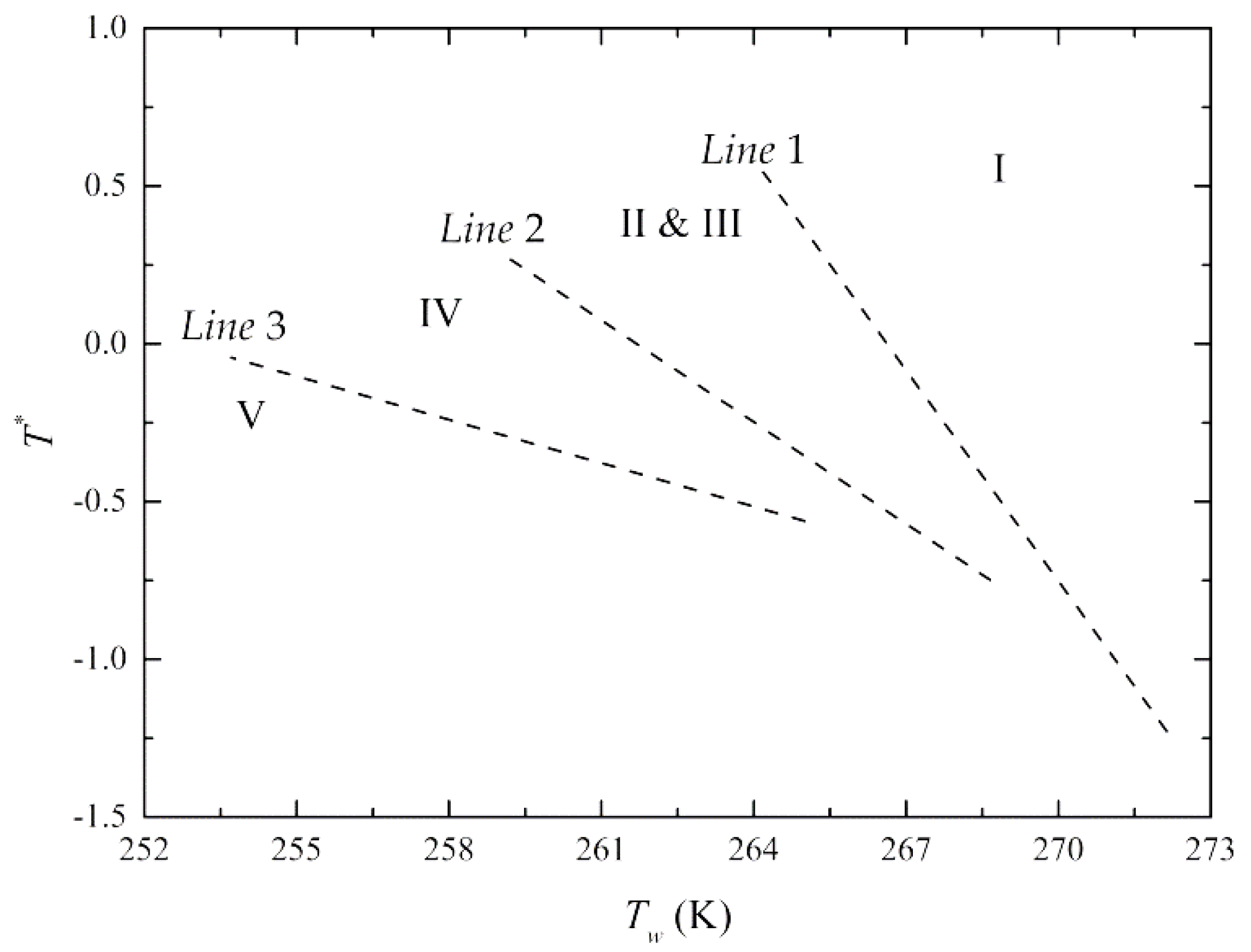
Wu et al. [16] classified the frost morphology as shown in Figure 1, which is based on the difference of absolute humidity between airflow and cold plate surface. However, both Kobayashi [13] and Wu et al. [16] could only recognize the crystal shape via map visualization. In order to facilitate the process for identifying the frost geometry, the parameter of the ordinate in Figure 2 is converted to a dimensionless temperature T*, which is inspired from some previous studies [17,18], and the unit of abscissa is Kelvin. This dimensionless parameter can represent the inclination of de-sublimation. The higher value it is, the higher possibility the de-sublimation occurs since the ratio of temperature difference below the triple point becomes dominant in this dimensionless parameter. As seen in the figure, the regions can be distinguished through three linear equations. The form of T* and equations are expressed as:
T * + 0.2230 × T w = 59.4574   for   L i n e 1
T * + 0.1076 × T w = 28.1582   for   L i n e 2
T * + 0.0459 × T w = 11.6015   for   L i n e 3
T * = log 10 T t p T w T d e w T w
where Tw is the surface temperature of the cold plate, Ttp is the temperature of water triple point, and Tdew is the dew point temperature. Equations (9)–(11) are applicable in the range of wall surface temperature (−20 < Tw < 0 °C) and the dimensionless temperature T* (−1.5 < T* < 0.5). Note that when T* becomes zero, this means the dew point temperature is equal to the triple point. This can be a border of the driving force between the condensation and de-sublimation. When T* is higher than zero, the dominant driving force is de-sublimation rather than condensation.
Based on Equations (9)–(11), each crystal geometry can also be recognized by using linear programming if the dew point temperature and the wall temperature are known. Based on the aforementioned approach, the steps of identifying the crystal geometry is elucidated as follows:
  • Determine the dew point temperature and cold plate temperature.
  • Input two parameters of step 1 into Equations (9)–(11) and compare the calculated value with the constant term of Equations (9)–(11).

2.2. Semi-Empirical Correlation

Notice that the frost thermal conductivity is strongly dependent on frost crystal and porosity [6,7,8]. However, the crystal shapes used in previous references are formed on the filament instead of the flat plate [13]. Hence, in the present study, a group of semi-empirical correlations (Equation (13)) that incorporating the crystal shape on the flat plate is proposed and the equation form for regression is based on Negrelli and Hermes [7].
k f k i = a ( k a k i ) b ε
ε = ρ i ρ f ρ i ρ a
where kf, ki (=2.22 W/m K), and ka (=0.0225 W/m K) are the thermal conductivities of frost, ice, and air, respectively. “a” and “b” are the correlation coefficients which are empirically fitted from the experimental data from several references. The corresponding values are listed in Table 1. ε is the porosity of the frost layer, ρ i (=917 kg/m3) is the density of ice, ρ f is frost density, and ρ a is air density in the frost layer. Furthermore, the experimental data shown in Figure 3a–c are taken from previous studies [2,5,6,8,9,11,19,20]. In Figure 3a, the experimental data of the region II and III are combined due to their similar shape that tends to grow crystal branch along with the cold plate and it also shows a good agreement in the range of porosity. Figure 3b,c shows that higher accuracy can be observed with higher porosity since these regions are the typical operating condition for the cold plate that contains much more data points. Although fewer data points were reported in the lower porosity regime, these correlations still offer good predictive ability as depicted in Figure 3b,c.

2.3. Assumptions and Calculating Procedures

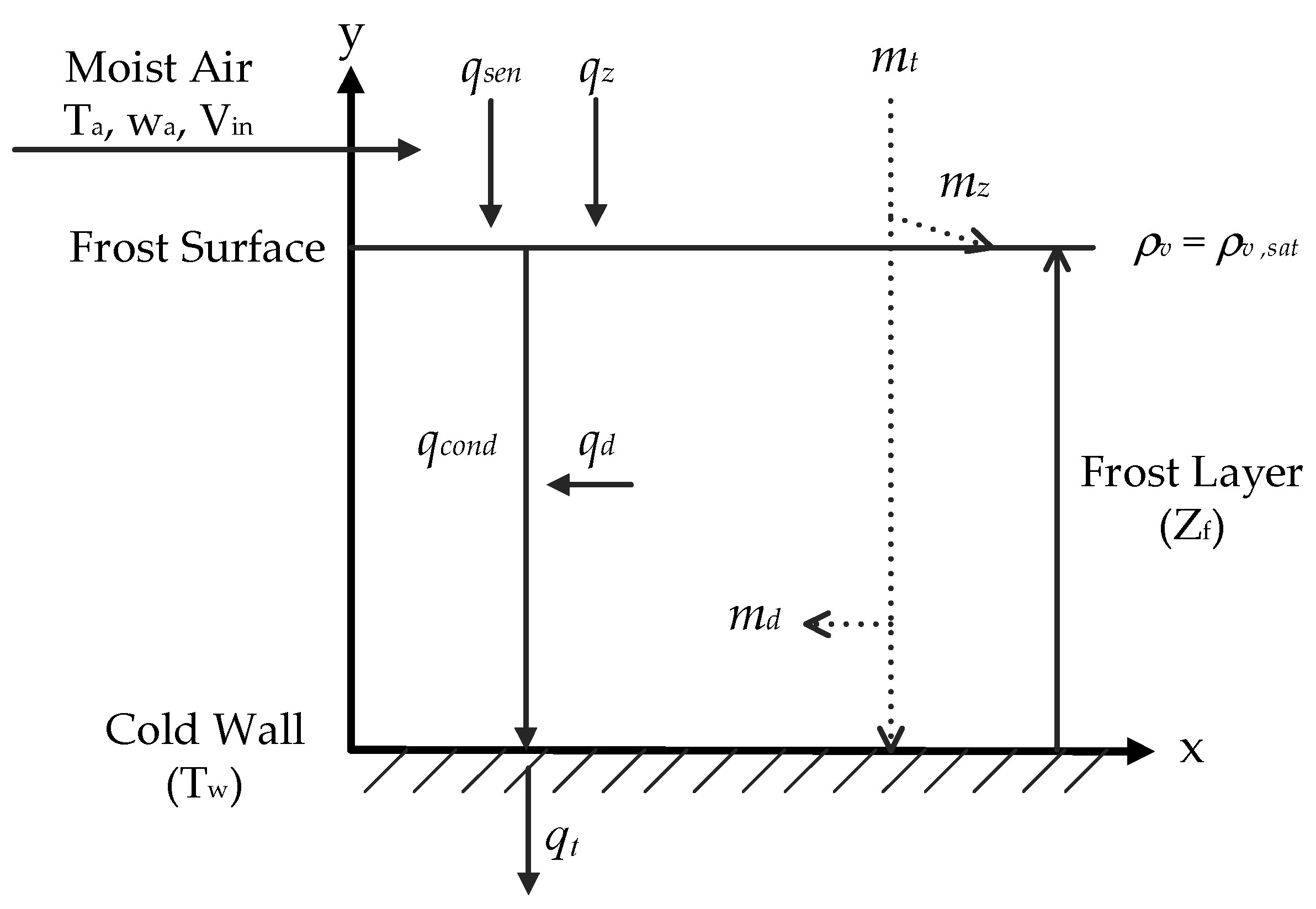
After developing correlations based on the frost crystal on the threshold of nucleation, the developed correlations were implemented into the numerical model for further simulation. The heat and mass transfer between air and frost for the present model is depicted in Figure 4. The growth of frost is analyzed by discretizing the frost layer into consecutive control volumes subject to heat and mass conservation. The corresponding sensible heat and latent heat transport are respectively calculated through the difference of temperature and absolute humidity at each time step. The numerical model is based on the following assumptions [21,22,23]:
  • The process of growing frost is a quasi-steady state.
  • The effects of convection and radiation are neglected in the frost layer.
  • The density distribution in the frost layer is uniform.
  • The mass and heat transfer are one-dimensional.
  • The thickness and density are invariant along the spanwise direction of the flat plate.
  • The pressure and temperature of airflow are uniform along the free stream direction.
  • The state of water vapor at the frost surface is saturation.
  • The air and water vapor are considered as ideal gas.
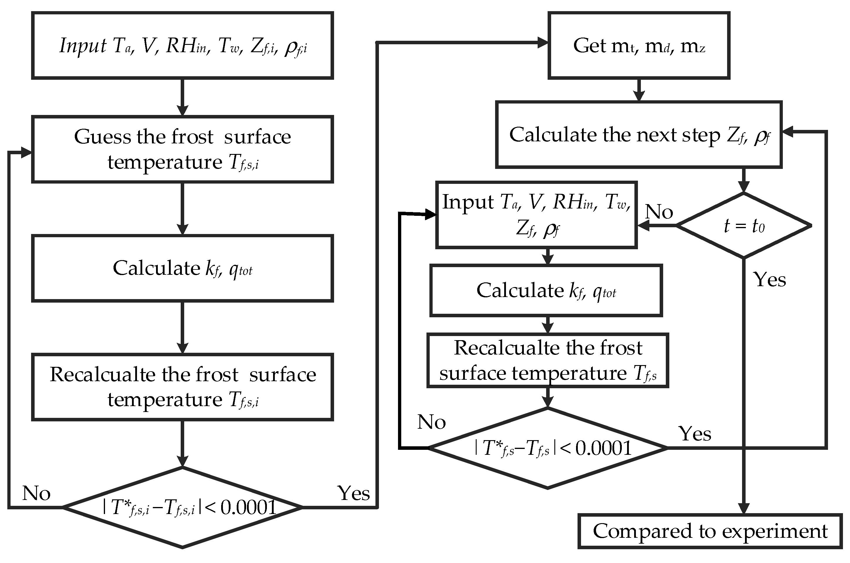
Based on the aforementioned assumptions, the impact of the frosting phenomenon in association with heat and mass transfer can be quantified by the frost thickness and density. Upon simulation, the properties for each state may change with air temperature, absolute humidity, air velocity, and wall temperature. The proposed algorithm shown in Figure 5 is capable of predicting the relevant influence on frost growth. The calculation process for each time step can be separated into three parts, and the details for each part are described in the followings:
  • The heat and mass transfer in this model can be determined by Yamakawa et al.’s correlation [24], which is determined by Ta, V, and RHin, and Lewis’s relation. The thermal conductivity can be determined by the frost density ( ρ f ).
  • The updated frost surface temperature (Tf,s) can be calculated by Equation (31). Yet, the updated frost surface temperature for each time step can be estimated through the bi-section method. The convergence of frost temperature between the initial guess and the calculating result is required during iterations.
  • Determine the mass transfer for densification (mρ) and mass transfer for increasing thickness (mz) by using Equations (20) and (23). Subsequently, the thickness (Zf) and density ( ρ f ) for the next time step can be obtained by discretizing equations, which are Equations (35) and (36).
  • Consider the calculating results as the new initial conditions, calculation then proceeds to the next time step.
  • When the calculation reaches the setting time, the calculation stops.
The properties of air in this model are obtained by the NIST REFPROP program [25].

2.4. Numerical Model

The governing equations for the mass balance in a control volume can be expressed as [22,26]:
D e f f d 2 ρ v d η 2 = C , η = y Z f
where ρ v is the concentration of water vapor in the frost layer, Deff represents the effective mass diffusivity in the porous media, η is a dimensionless coordinate parameter along the y-direction, and C is the absorption rate of water vapor in the frost layer. Since the density profile in the y-direction and porosity of the frost layer are homogeneous [22,27], C can be viewed as a constant. Zf is the thickness of the frost layer.
From the perspective of energy balance, the heat transferred by conduction in the frost layer is mainly controlled by phase change. The enthalpy of water vapor does not vary, so that the energy governing equations for each control volume becomes [22]:
k f d 2 T d η 2 = L l a t D e f f d 2 ρ v d η 2
where Llat (=2834 kJ/kg) is the latent heat of sublimation of ice. The thermal conductivity in this model adopts the correlations based on the crystal shape in the present model.
The heat flux including sensible and latent heat transfer from moist air to the frost layer is in the following form:
q t o t = q s e n + q l a t = h s e n ( T a T f , s ) + h l a t L l a t ( ρ v , ρ f , s )
where qsen and qlat are the sensible heat and latent heat transfer through the frost layer, respectively. hsen is sensible heat transfer coefficient, hlat is mass transfer coefficient, Ta is the temperature of airflow, Tf,s is the frost surface temperature, ρ v , is the concentration of water vapor in airflow, and ρ f , s is the saturated humidity on the frost layer. In order to obtain the heat flux going through the frost layer, it is necessary to calculate the sensible heat transfer coefficient and mass transfer coefficient from Equations (18) and (19).
h s e n = 0.034 Re 0.8 k a L c
h l a t = h s e n C p , a L e 2 / 3
where Re is Reynold number of the flat plate, Lc is the characteristic length of the cold plate, Cp,a is specific heat capacity, and Le is the Lewis relation connecting the heat and mass transfer and the value ranges from 0.7 to 1 [9,21]. Equation (18) is developed by Yamakawa et al. [24] and the equation is widely used in estimating the sensible heat transfer coefficient for frost growth on the flat plate [21,22,23,28]. Furthermore, the mass transfer can be divided into two parts:
m t = h l a t ( ρ v , ρ f , s ) = m z + m d = ρ f d Z f d t + Z f d ρ f d t
where mz and md represent the contribution to the growth rate of frost and the rate of densification, respectively. The amount of densification is described by Fickian diffusion based on the gradient of water vapor concentration [21,22,23,29,30,31].
m d = D e f f Z f d ρ v d η | η = 1
The assumption of the saturated state of water vapor at the frost surface described as Equation (22) is applied in some previous studies [21,22,23,31]. With the assumption of ideal gas and incorporating the Clausius–Clapeyron expression, Equation (21) can be rewritten into Equation (23) [22,30].
ρ v = ρ v , s a t , η = 1
m d = D e f f ( L l a t M v 2 R 2 T f , s 3 ) ( p 0 p v , s a t p 0 p v , s a t ) d T d y | y = Z f
where R is the universal ideal gas constant, Mv is the molar mass of water vapor, p 0 is atmospheric pressure, and p v , s a t is saturated pressure of water vapor. Since no water vapor passes through the cold plate, the gradient of concentration of water vapor at the cold plate can be described by Equation (24). Therefore, Equation (15) can be integrated to yield Equation (25), and Equation (21) can also be transformed into Equation (26).
d ρ v d η | η = 0 = 0
d ρ v d η | η = 1 = C D e f f
m d = D e f f Z f d ρ v d η | η = 1 = D e f f C 1 Z f , C 1 = C D e f f
By comparing Equations (23) and (26), C1 can be expressed as:
C 1 = ( L l a t M v 2 R 2 T f , s 3 ) ( p 0 p v , s a t p 0 p v , s a t ) d T d η | η = 1
The boundary conditions for the present numerical model are shown in Figure 4, where the boundary conditions of the energy equation are given as:
T = T w , η = 0
k f Z f d T d η | η = 0 = q t o t , η = 0
k f Z f d T d η | η = 1 = h s e n ( T a T f , s ) + L l a t ( m t m d ) , η = 1
In Equation (30), the mass transfer of densification only occurs in the frost layer; hence, the diffusion term should be eliminated when depicting the heat transfer at the frost surface. Furthermore, the total heat transfer should be completely removed from the cold plate. By manipulating Equations (16) and (28)–(30), the temperature profile in the frost layer can be obtained as follows:
T ( η ) = L l a t D e f f C 1 2 k f η 2 + Z f q t o t k f η + T w
Hence, the frost surface temperature is given when η is equal to one. In this study, the effective diffusivity (Deff) in porous media is affected by the tortuosity and porosity and is expressed as Equation (32) [22,28,32]. The mass diffusivity is taken from the monograph of Sherwood and Pigford [33]:
D e f f = D v ε τ ,   τ = ε 1 1 ε
D v = 9.26 × 10 7 1 p ( T 2.5 T + 245 )
where ε is the porosity of the frost layer, and τ is tortuosity of the frost layer. In Equation (33), p is total pressure with the unit of kPa. The temperature of diffusivity adopts the frost surface temperature in Kelvin.
The saturation pressure can be estimated via the empirical equation from ASHRAE [34]. The following relation is shown below:
ln p v , s a t = a 1 T + a 2 + a 3 T + a 4 T 2 + a 5 T 3 + a 6 T 4 + a 7 ln T
where p in Pa, T in K. The applicable range and corresponding coefficients are shown in Table 2. After calculation of all the properties, the frost thickness and average density of the next time step can be predicted by:
Z f | t + Δ t = Z f | t + m z ρ f Δ t
ρ f | t + Δ t = ρ f | t + m d Z f Δ t
To start the simulating process, the initial value of surface temperature, average density and thickness must be given. These initial values are introduced from previous studies and expressed as follows [6,22,35]:
Average density: ρ f , i = 30   kg / m 3
Thickness: Z f , i = 1 × 1 0 5   m
Surface temperature: T f , s = T w

3. Results and Discussion

3.1. Analysis of Collected Data and Comparison of Correlations

The experimental data of frost thermal conductivity containing porosity in the range of 0.5 to 1 [2,5,6,8,9,11,19,20] are shown in Figure 6. The corresponding air temperature of these data is spanning from −3.5 to 25 °C with absolute humidity ranging from 0.974 to 13.92 g/kg. The cold plate temperature varies from −5 to −30 °C. As seen in the figures, the thermal conductivity increase as the porosity reduces. This is because the deposition of the frost layer raises the density, thereby reducing the ratio of air in the frost layer. For further examination of the experimental data, it is found that the thermal conductivity shows comparatively small deviations when the porosity exceeds 0.8. This is because the frost may contain large air space during the initial growth period. As a result, the values are close to air thermal conductivity. There had been some studies that proposed the correlations in terms of polynomial form [2,3,4,5] and Hayashi et al. [11] to support this explanation. However, after comprehensively comparing the collected data, it can be found that the experimental data is split into three directions based on the crystal shape so that only one polynomial function is not able to portray completely the thermal conductivity. Comparing with the frost shape of each region, irregular and flake crystals are prone to extending their branch horizontally [10,16], therefore resulting in a more packed structure and higher thermal conductivity. With the increase of driving force of frost formation, the crystal shapes in region IV and V gradually change their growing direction from parallel alignment to normal direction [10,16,36], thereby sparing the space to entrap more circulating air in the frost layer and decreasing the frost thermal conductivity accordingly. Note that Na and Webb [6] and Negrelli and Hermes [7,8] adopted the same philosophy to categorize the thermal conductivity. In their studies, the thermal conductivity is decreased with the decline of the cold plate temperature. This phenomenon is also supported by Huang et al. [37]. This is because the driving potential of frost growth can be calculated by R ( T t p T f , s ) ln ( p v p v , s a t ) . When the cold plate temperature decreases, the thickness is increased and the densification is mitigated due to the balance of mass conservation, hence, the thermal conductivity is reduced.
In addition to showing the collected data, Figure 6 also depicts a series of comparisons between experimental data and some proposed correlations [6,7,12]. In Figure 6a, although Auracher [12] provided a method that was based on the frost structure to calculate the thermal conductivity, the growth of frost inside the frost layer does not follow a definite path. Therefore, the developed correlation is still not accurate enough. Furthermore, as seen in the figure, the values predicted by Auracher [12] are approximately 63% less than the present correlation because the method considered the thermal resistances of air and ice to be in the series arrangement [12]. As compared to Auracher’s correlation, the correlation by Na and Webb is moderately improved to 48% via adding weighting factor, yet it still yields almost 20% deviation as compared to experimental data [6]. To achieve higher accuracy of prediction, Negrelli and Hermes [7] investigating more data points to develop a correlation form as shown in Equation (13) with a mean deviation of around 10% while the data set is based on crystal geometry.
As shown in Figure 6b, an obvious difference exists between these four correlations. The main reason is that the working condition of frost crystal morphology in their developed model is applicable for the flat plate subject to forced convection [16] and it takes the effect of humidity difference into account. In Figure 6b, the values estimated by Auracher [12] and Na and Webb [6] are more in line with the experimental data as depicted in Figure 6a, This is because region IV is the most common shape upon frost morphology, meaning that the correlation can be better described with more experimental data. Note that the correlation by Negrelli and Hermes over-estimated the test data with 43% deviation. The reason to explain this departure is that some crystal geometry in Kobayashi’s map [13] in this temperature range (−21 < Tw < −10 °C) is irregular or dendrite where the frost crystal develops its branch horizontally and provides higher thermal conductivity. By contrast, the column-like pattern reducing the thermal conductivity is shown in Wu et al.’s examination for frost morphology [16] in this working range. By using more rationally based frost morphology, the present correlation shows a better agreement with the experimental data.
In Figure 6c, it is found that the three correlations are almost in line with each other, yet the predicted results are under-estimated. This is also attributed to the category of frost crystal used in their study that does not account for the effect of humidity. To improve the predictive ability of the numerical model, the equation with Wu et al.’s map [16] is used. As seen in the figure, the predictive deviations are slightly reduced to 38%. Similar results can be obtained by the other three correlations when the porosity is higher than 0.8, but when the porosity is reduced to 0.8, the increase of thermal conductivity becomes relatively sharp. Although the correlations by Auracher [12] or Negrelli and Hermes. [7] are able to predict partial experimental data, the present correlation can generate the results following the main increasing trend of experimental data to improve the predictive ability.

3.2. Performance of Numerical Model by Using Present Correlations

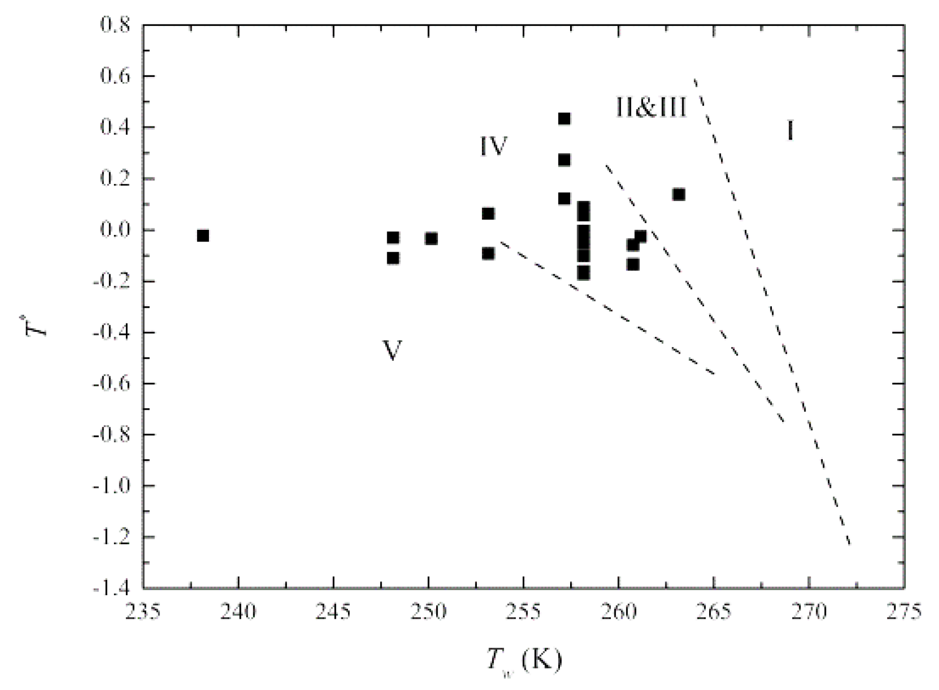
To employ the numerical model, the frost crystal for specific working conditions should be included. Hence, crystal classification is first performed from Equations (9)–(12). As seen in Figure 7, the collected data in Table 3 is taken from Leoni et al. [9], Yang and Lee [18], Lee and Ro [22,38], Lee et al. [39], Negrelli et al. [8], and Wang et al. [23]. The temperature ranges from 0 to 15 °C, the corresponding absolute humidity is spanning from 1.58 to 6.33 g/kg, and the cold plate temperature varies from −10 to −35 °C. Though the velocity imposes a minor influence on the growth of the frost layer [9,37], the velocity is also included in the present analysis and it changes from 1 to 5 m/s. As seen in the figure, most collecting data fall into region IV which is the most commonly operating conditions in refrigeration systems. Note that the data points surpassing the temperature limitation (Tw < 253 K) of frost morphology can still be identified. These results imply that the procedure can be viably employed in classification when the operating point is out of the range of frost map.
The predictive ability of frost density and frost thickness between the proposed numerical model and other correlations are shown in Figure 8. Note that the frost growth is a transient behavior; hence, the frost thickness shown in Figure 8 is fixed at the time of 60 min. In Figure 8a, the estimated density from the Auracher correlation is much higher than the experimental results. Since the heat transfer rate barely changed in each time step, the temperature difference between cold plate and frost surface can be estimated as QΔy/kf from the Fourier law, where Q is heat flux for each time step. Initially, Δy is small enough, hence, the temperature difference is mainly controlled by kf. From Figure 6b, Auracher’s correlation predicts a lower thermal conductivity, thereby leading to over-predict the frost surface temperature. Consequently, from Equation (23), the mass transfer raises due to the rise of surface temperature, therefore increasing the frost density and mitigating the growth of frost. Accordingly, frost thickness is under-predicted by Auracher correlation as observed in Figure 8b. On the contrary, the results predicted by the Negrelli and Hermes correlations are opposite to the foregoing discussion. This is because their predicted thermal conductivities are the largest among relevant predictions as seen in Figure 6b. As a result, the resultant smallest temperature gradient reduces the effective mass diffusion. Analogous predicted results by Auracher and Negrelli et al. are also shown from Breque and Nemer [26]. Neither Auracher nor Negrelli and Hermes correlation can offer good predictions against the frost thickness and density at the same time. The proposed calculation method not only shows better predictive ability regarding thermal conductivities as shown in Figure 6b but also gives good predictions for density and is especially accurate when the frost density is lower than 125 kg/m3. Even when the density exceeds 125 kg/m3, the proposed calculation still outperforms the prediction of Negrelli and Hermes [7] by 14%. This is because they over-predict the thermal conductivity for the frost having pole and needle crystal morphology by 43%. Note that the predictive performance between Na and Webb [6] and the proposed model seems comparable as depicted in Figure 8. To distinguish the predictive ability amid these two correlations, relative root mean square error (RRMSE) is used to quantify the difference. This error is expressed as follows [20]:
RRMSE = 1 N i = 1 N ( γ c a l γ exp ) 2 1 N i = 1 N γ exp × 100
where N represents the number of samples, and γcal and γexp stand for the calculated and experimental data, respectively. RRMSE can symbolize the distribution and accuracy of the calculated value after normalization. The smaller the RRMSE value is, the greater the accuracy becomes. In Figure 9a, one can see the prominent improvement either by Na and Webb correlation or the present model. In fact, the RRMSE of the present model shows approximately 5% lower for each working time. This improvement can also be found in Figure 8a especially when the frost density is high. In fact, at the higher range of density, the present model shows improvement in predicting density by about 5–10% when compared to Na and Webb correlation. In essence, in that density range (150–300 kg/m3), the present model has a great agreement in the corresponding porosity (0.75–0.83) and the density is strongly related to the thermal conductivity, hence showing less error.
The effects on thickness caused by different correlations are presented in Figure 9b. As seen in the figure, Na and Webb correlation [6] and the present model offer smaller predictive errors when the time of frost deposition is 60 min. Noting that the data from the present model shows a relatively consistent tendency with the measured thickness as seen in Figure 8b. As compared to the trend of density, the trend of thickness cannot be influenced significantly. This is because the thickness is not strongly affected by thermal conductivity. When the thickness increases with time, the heat and mass transfer depicted in Equation (17) decreases with the rise of the frost surface temperature. Nevertheless, as the time proceeds, the RRMSE of thickness predicted from Auracher [12] obviously drops from 26% to 18.5%, which is lower than the present model. This can be attributed to the lower thermal conductivity, which increases the frost surface temperature. Upon densification, the increase of frost surface temperature also promotes the rise of density that may lead to melting effect at the surface, followed by water permeation into the frost layer to occupy the air space [9,40]. Since the under-prediction of thermal conductivity from Auracher could result in the aforementioned effect, the thickness can be estimated with a smaller value as compared to the experimental data with less error. The same reason applies when explaining the influence caused by the Na and Webb correlation [6]. With the higher thermal conductivity predicted by the present model, the lower temperature difference in the frost layer is encountered. Therefore, the frost growth rate cannot be curbed. According to the analysis, the more suitable thermal conductivity for prediction with higher accuracy should lie in the region which is enveloped by Auracher [12] and the present model. By using the proposed model, it can be expected that better predictions of frost density, thickness, and thermal conductivity can be attainable.

4. Conclusions

In this study, a rational procedure for identifying the crystal shape is proposed to estimate the frost density, thickness, and thermal conductivity. The method transforms the difference of absolute humidity into dimensionless temperature to account for the influence of dew point and triple point. The developed model is compared between existing correlations and experimental data for specific frost crystal. Based on the detailed comparisons, the proposed model shows the best predictive ability upon frost properties when compared to existing correlations. The major conclusions are presented as follows:
  • The proposed procedures of linear programming for identifying the crystal geometry are in line with the previous frost crystal map.
  • For identifying the crystal structure, the proposed model can identify the corresponding frost shape by a dimensionless temperature and the surface temperature.
  • Comparisons of the proposed model and existing correlations indicate that the proposed model and the Na and Webb correlations are comparable in predicting the frost properties like thickness and thermal conductivity while the present model yields about 5% better prediction ability in frost density than Na and Webb’s correlation.
  • The proposed calculation method not only shows better predictive ability with thermal conductivities, but also gives good predictions for density and is especially accurate when the frost density is lower than 125 kg/m3. Even when the density exceeds 125 kg/m3, the proposed calculation still outperforms the prediction of Negrelli and Hermes [7] by 14%.

Author Contributions

Conceptualization, S.-M.L.; methodology, S.-M.L.; validation, S.-M.L.; investigation, S.-M.L.; writing—original draft preparation, S.-M.L.; writing—review and editing, all authors; visualization, S.-M.L.; supervision, K.-S.Y. and C.-C.W.; project administration, C.-C.W. All authors have read and agreed to the published version of the manuscript.

Funding

This research was funded by Ministry of science and technology, Taiwan under contract 108-2221-E-009-037-MY3.

Institutional Review Board Statement

Not applicable.

Informed Consent Statement

Not applicable.

Data Availability Statement

The data is available upon request.

Acknowledgments

This research was funded by the Ministry of Science Technology of Taiwan, under grant number: MOST 108-2221-E-009-037-MY3.

Conflicts of Interest

The authors declare no conflict of interest.

References

  1. Song, M.; Dang, C. Review on the measurement and calculation of frost characteristics. Int. J. Heat Mass Transf. 2018, 124, 586–614. [Google Scholar] [CrossRef]
  2. Yonko, J.D. An investigation of the thermal conductivity of frost while forming on a flat horizontal plate. ASHRAE Trans. 1967, 73, 1.1–1.11. [Google Scholar]
  3. Brian, P.L.T.; Reid, R.C.; Shah, Y.T. Frost Deposition on Cold Surfaces. Ind. Eng. Chem. Fundam. 1970, 9, 375–380. [Google Scholar] [CrossRef]
  4. Östin, R.; Andersson, S. Frost growth parameters in a forced air stream. Int. J. Heat Mass Transf. 1991, 34, 1009–1017. [Google Scholar] [CrossRef]
  5. Lee, K.; Lee, T.; Kim, W. Heat and mass transfer of parallel plate heat exchanger under frosting condition. Korean J. Air-Cond. Refrig. Eng. 1994, 6, 155–165. [Google Scholar]
  6. Na, B.; Webb, R.L. New model for frost growth rate. Int. J. Heat Mass Transf. 2004, 47, 925–936. [Google Scholar] [CrossRef]
  7. Negrelli, S.; Hermes, C.J. A semi-empirical correlation for the thermal conductivity of frost. Int. J. Refrig. 2015, 58, 243–252. [Google Scholar] [CrossRef]
  8. Negrelli, S.; Nascimento, V.S., Jr.; Hermes, C.J. A study of the effective thermal conductivity of frost formed on parallel plate channels. Exp. Therm. Fluid Sci. 2016, 78, 301–308. [Google Scholar] [CrossRef]
  9. Leoni, A.; Mondot, M.; Durier, F.; Revellin, R.; Haberschill, P. Frost formation and development on flat plate: Experimental investigation and comparison to predictive methods. Exp. Therm. Fluid Sci. 2017, 88, 220–233. [Google Scholar] [CrossRef]
  10. Zhang, T.; O’Neal, D.L.; McClain, S.T. Analysis of frost thickness and roughness growth from the perspective of frost crystal structure. Int. J. Refrig. 2020, 112, 314–323. [Google Scholar] [CrossRef]
  11. Hayashi, Y.; Aoki, A.; Adachi, S.; Hori, K. Study of Frost Properties Correlating With Frost Formation Types. J. Heat Transf. 1977, 99, 239–245. [Google Scholar] [CrossRef]
  12. Auracher, H. Effective Thermal Conductivity of Frost. Int. Symp. Heat Mass Transf. Refrig. Cryog. 1986, 285–302. [Google Scholar] [CrossRef]
  13. Kobayashi, T. On the Habit of Snow Crystals Artificially Produced at Low Pressures. J. Meteorol. Soc. Jpn. 1958, 36, 193–208. [Google Scholar] [CrossRef] [Green Version]
  14. Liu, Z.; Gou, Y.; Wang, J.; Cheng, S. Frost formation on a super-hydrophobic surface under natural convection conditions. Int. J. Heat Mass Transf. 2008, 51, 5975–5982. [Google Scholar] [CrossRef]
  15. Piucco, R.O.; Hermes, C.J.; Melo, C.; Barbosa, J.R. A study of frost nucleation on flat surfaces. Exp. Therm. Fluid Sci. 2008, 32, 1710–1715. [Google Scholar] [CrossRef]
  16. Wu, X.; Dai, W.; Xu, W.; Tang, L. Mesoscale investigation of frost formation on a cold surface. Exp. Therm. Fluid Sci. 2007, 31, 1043–1048. [Google Scholar] [CrossRef]
  17. Mao, Y.; Besant, R.; Chen, H. Frost characteristics and heat transfer on a flat plate under freezer operating conditions: Part I, Experimentation and correlations. Ashrae Trans. 1999, 105, 231. [Google Scholar]
  18. Yang, D.-K.; Lee, K.-S. Dimensionless correlations of frost properties on a cold plate. Int. J. Refrig. 2004, 27, 89–96. [Google Scholar] [CrossRef]
  19. Tokura, I.; Saito, H.; Kishinami, K. Study on Properties and Growth Rate of Frost Layers on Cold Surfaces. J. Heat Transf. 1983, 105, 895–901. [Google Scholar] [CrossRef]
  20. Zendehboudi, A.; Hosseini, S.H.; Ahmadi, G. Modeling of frost thermal conductivity on parallel surface channels. Measurement 2019, 140, 293–304. [Google Scholar] [CrossRef]
  21. Lee, K.-S.; Kim, W.-S.; Lee, T.-H. A one-dimensional model for frost formation on a cold flat surface. Int. J. Heat Mass Transf. 1997, 40, 4359–4365. [Google Scholar] [CrossRef]
  22. Lee, Y.; Ro, S. Analysis of the frost growth on a flat plate by simple models of saturation and supersaturation. Exp. Therm. Fluid Sci. 2005, 29, 685–696. [Google Scholar] [CrossRef]
  23. Wang, W.; Guo, Q.; Lu, W.; Feng, Y.; Na, W. A generalized simple model for predicting frost growth on cold flat plate. Int. J. Refrig. 2012, 35, 475–486. [Google Scholar] [CrossRef]
  24. Yamakawa, N.; Takahashi, N.; Ohtani, S. Forced convection heat and mass transfer under frost conditions. J. Heat Transf.-Jpn. Res. 1972, 1, 1–10. [Google Scholar]
  25. Lemmon, E.; Huber, M.; McLinden, M. NIST Standard Reference Database 23: Reference Fluid Thermodynamic and Transport Properties-REFPROP; Version 8.0; National Institute of Standards and Technology, Standard Reference Data Program: Gaithersburg, MD, USA, 2007. [Google Scholar]
  26. Brèque, F.; Nemer, M. Frosting modeling on a cold flat plate: Comparison of the different assumptions and impacts on frost growth predictions. Int. J. Refrig. 2016, 69, 340–360. [Google Scholar] [CrossRef]
  27. Brian, P.L.T. Cryogenic frost properties. Cryog. Technol. 1969, 5, 205–212. [Google Scholar]
  28. Hermes, C.J.; Piucco, R.O.; Barbosa, J.R.; Melo, C. A study of frost growth and densification on flat surfaces. Exp. Therm. Fluid Sci. 2009, 33, 371–379. [Google Scholar] [CrossRef]
  29. Sherif, S.; Raju, S.; Padki, M.; Chan, A. A semi-empirical transient method for modelling frost formation on a flat plate. Int. J. Refrig. 1993, 16, 321–329. [Google Scholar] [CrossRef]
  30. Le Gall, R.; Grillot, J.; Jallut, C. Modelling of frost growth and densification. Int. J. Heat Mass Transf. 1997, 40, 3177–3187. [Google Scholar] [CrossRef]
  31. Ismail, K.; Salinas, C. Modeling of frost formation over parallel cold plates. Int. J. Refrig. 1999, 22, 425–441. [Google Scholar] [CrossRef]
  32. Mezedur, M.M.; Kaviany, M.; Moore, W. Effect of pore structure, randomness and size on effective mass diffusivity. AIChE J. 2002, 48, 15–24. [Google Scholar] [CrossRef] [Green Version]
  33. Sherwood, T.K.; Pigford, R.L. Absorption and Extraction; McGraw-Hill: New York, NY, USA, 1952. [Google Scholar]
  34. ASHRAE. American Society of Heating, Refrigerating and Air-Conditioning Engineers; ASHRAE Inc.: Atlanta, GA, USA, 2009. [Google Scholar]
  35. Jones, B.W.; Parker, J.D. Frost Formation with Varying Environmental Parameters. J. Heat Transf. 1975, 97, 255–259. [Google Scholar] [CrossRef]
  36. Sahin, A.Z. An experimental study on the initiation and growth of frost formation on a horizontal plate. Exp. Heat Transf. 1994, 7, 101–119. [Google Scholar] [CrossRef]
  37. Huang, L.; Liu, Z.; Liu, Y.; Gou, Y. Experimental study of frost growth on a horizontal cold surface under forced convection. J. Mech. Sci. Technol. 2010, 24, 1523–1529. [Google Scholar] [CrossRef]
  38. Lee, Y.; Ro, S. Frost formation on a vertical plate in simultaneously developing flow. Exp. Therm. Fluid Sci. 2002, 26, 939–945. [Google Scholar] [CrossRef]
  39. Lee, K.-S.; Jhee, S.; Yang, D.-K. Prediction of the frost formation on a cold flat surface. Int. J. Heat Mass Transf. 2003, 46, 3789–3796. [Google Scholar] [CrossRef]
  40. Liu, Y.; Liu, Z.; Huang, L.; Sun, J. Fractal model for simulation of frost formation and growth. Sci. China Ser. E Technol. Sci. 2010, 53, 807–812. [Google Scholar] [CrossRef]
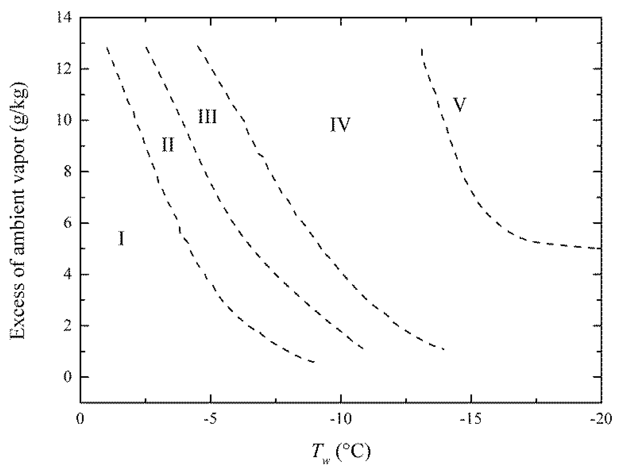
Figure 1. Illustration of frost morphology on the flat plate from Wu et al. [16]. I: super-cooled water droplets, II: irregular crystals, III: flake crystals, IV: needle and pole crystals, and V: feather crystals.
Processes 09 00412 g001
Figure 2. Illustration of frost morphology with the dimensionless temperature of the vertical axis. I: super-cooled water droplets, II and III: irregular and flake crystals, IV: needle and pole crystals, and V: feather crystals.
Processes 09 00412 g002
Figure 3. Best fitting based on the form of Equation (13) with different crystal shapes.
Processes 09 00412 g003
Figure 4. Schematic of the physical model and boundary conditions.
Processes 09 00412 g004
Figure 5. Flowchart of iterations in the predictive model for frost.
Processes 09 00412 g005
Figure 6. Comparison of thermal conductivity subject to different crystal geometry.
Processes 09 00412 g006
Figure 7. Operating points for numerical model classified by proposed procedure [8,9,18,22,23,38,39]. I: super-cooled water droplets, II: irregular crystals, III: flake crystals, IV: needle and pole crystals, and V: feather crystals.
Processes 09 00412 g007
Figure 8. Comparison between experimental data and numerical results with correlations at 60 min.
Processes 09 00412 g008
Figure 9. The error analysis of predicted density and thickness by means of different correlations.
Processes 09 00412 g009
Table 1. The fitting coefficients of Equation (13) and crystal shape for each region.
RegionMorphologyab
II and IIIIrregular and flake crystals1.5450.801
IVNeedle and pole crystals2.9441.030
VFeather crystals1.7430.860
Table 2. Coefficients in the water vapor saturation pressure equation.
Coefficients−100 ≤ T ≤ 0 °C0 ≤ T ≤ 200 °C
a 1 −5674.5359−5800.2206
a 2 6.39252471.3914993
a 3 9.677843 × 10 1 4.8640239 × 10 2
a 4 6.2215701 × 10 7 4.17646768 × 10 5
a 5 2.0747825 × 10 9 1.4452093 × 10 8
a 6 9.484024 × 10 13 0
a 7 4.16350196.5459653
Table 3. Testing conditions of the points used in the numerical model.
No.Ta (°C)wa (g/kg)Tw (°C)Vin (m/s)
1156.33−152.5
2155.00−151.6
3125.20−12.42
4124.30−12.42
5106.33−251
6106.33−251.75
7106.10−151.2
8105.30−201.75
9105.00−151.6
10104.31−251
1154.31−351
1254.31−151
1354.31−151
1454.00−151.6
1553.22−152.5
1653.20−151
1753.00−201.6
1853.00−151.6
1953.00−101.6
2043.80−151.2
2102.72−165
2202.00−165
2301.58−165
Publisher’s Note: MDPI stays neutral with regard to jurisdictional claims in published maps and institutional affiliations.