Article

Reducing the Internal Stress of Fe-Ni Magnetic Film Using the Electrochemical Method

School of Chemical Engineering and Technology, Tianjin University, Tianjin 300350, China
*
Author to whom correspondence should be addressed.
Processes 2021, 9(11), 1883; https://doi.org/10.3390/pr9111883
Submission received: 8 September 2021 / Revised: 26 September 2021 / Accepted: 17 October 2021 / Published: 21 October 2021

Abstract

:
Soft magnetic materials are important functional materials in the electrical engineering, radio, and high-tech fields, but thin and brittle flakes present challenges to the manufacturing industry. In this study, the effect and mechanism of saccharin sodium in reducing the internal stress of Fe-Ni magnetic films were analyzed. The effects of the pH value, temperature, and the concentration of saccharin sodium on the deposition process of Fe-Ni alloys were investigated. The polarization curve of the Fe-Ni alloy deposition process was measured by using a multifunctional electrochemical workstation, and the morphology and crystal structure were measured by a scanning electron microscope (SEM) and X-ray diffraction (XRD). The results show that saccharin sodium significantly reduced the stress of the iron-nickel magnetic film; the mechanism through which the internal stress was reduced is analyzed in this paper. Briefly, the Fe2+ and the amino group of saccharin sodium synthesized a metal complex with positive charge on the surface of the electrode, which prevented the hydrogen ions from approaching the cathode and increased the discharge activation energy of the hydrogen ion, which reduced the hydrogen evolution and improved the internal stress of the coating. This research will help to solve the challenges of producing magnetic film, and promotes the application of new stress-reducing agents.

1. Introduction

Soft magnetic materials are important functional materials in the fields of electrical engineering, radio, and high-tech [1,2,3]. With the advent of information technology and automation, soft magnetic materials have played an irreplaceable role in actual production. Soft magnetic materials have the characteristics of high permeability, low coercivity, high saturation magnetic induction and low residual magnetic induction. Therefore, soft magnetic materials are widely used in the manufacture of stators and rotors for generators and motors, the iron cores of transformers and inductors, magnetic recording heads, magnetic shields, etc. Their application fields include power supply, switching power supply, instrumentation, vehicle electronics, and solar energy, and they play a key role in energy conversion throughout the entire world [4,5,6]. In our country, with the rapid development of high-tech fields, the demand for soft magnetic materials in various fields is increasing. In addition, in order to manufacture high-frequency, high-efficiency, energy-saving motors and other high-end products, China is expanding the application of soft magnetic materials, developing high-performance soft magnetic materials and new processing and manufacturing technologies. It is worth mentioning that in the field of power electronics, the improvement of efficiency will promote the development of smart and flexible transformers, potentially reducing global energy consumption by 20% [7]. Therefore, an increasing number of researchers are paying attention to magnetic-based passive components (transformers, inductors, and capacitors) and solving the challenges posed by transformers and inductors; both require soft magnetic cores (low coercivity) to achieve high power density.
Permalloy (iron-nickel alloy) is a soft magnetic alloy with a wide range of applications. It has a very high magnetic permeability, albeit under a weak magnetic field, and the adjustability of its composition is broad; in particular, its magnetic properties can be adjusted by changing the composition and heat treatment process [8,9,10,11,12,13,14,15,16,17,18,19,20,21,22,23,24,25]. In addition, amorphous and nanocrystalline alloys are currently very advanced materials. The unique nanostructure and extremely thin flakes make the hysteresis loss smaller while still maintaining a considerable magnetic induction saturation [26,27,28,29,30,31]. However, permalloys, like amorphous and nanocrystalline alloys, have some problems that cannot be ignored, such as their greater brittleness, their difficult processing, and their complicated production processes, which seriously affect the development of soft magnetic materials for different application fields. As is well known, when the internal stress is distributed in the coating, the coating produces stress corrosion. In addition, internal stress increases the porosity and brittleness of the coating. During electroforming, in order to make the electroforming mold easy to separate from the prototype, the internal stress of the electroforming layer should be small, otherwise it will cause blisters, deformation, and difficult peeling. In early research, the coercive force of soft magnetic amorphous alloy FePC was as high as 240 A/m, which was related to the high internal stress introduced during the quenching process. Moreover, the coercivity of amorphous alloy strips of FeNiPB prepared by melt spin-quenching technology was about 8 A/m [32,33]. These experimental results proved that eliminating the internal stress can significantly reduce the coercivity of the alloy, thereby reducing the hysteresis loss of the soft magnetic alloy [34,35,36,37,38,39].
Based on the above background, this study used the electrochemical method to solve the internal stress problem of the iron-nickel alloy, which is widely used in soft magnetic materials. The electrochemical method has obvious advantages. On the one hand, the process of its operation is simple, and its operating condition at room temperature is mild, which is conducive to industrial production and popularization. On the other hand, using electrochemical production methods, the film can be manufactured at fixed points, the size of the film can be small, and the structure and shape are easy to control; in particular its energy consumption is reduced [40,41,42]. In the electroplating industry, saccharin sodium and others have been found to eliminate cavities, pinholes, and gas marks during nickel plating, but they have different effects in different research systems, and the mechanism of surfactants has not been thoroughly explored [43,44,45,46,47].
In this study, it was found that saccharin sodium can significantly reduce the internal stress of iron-nickel magnetic film under new operating conditions, and we analyzed the mechanism through which saccharin sodium reduces internal stress. This fundamental research will help to promote the development of new stress-reducing agents. It is beneficial to apply saccharin sodium in a wider range to solve the problem of the internal stress of soft magnetic materials, in order to promote the industrial production of magnetic thin films through electrochemical methods.

2. Experiment

The Fe-Ni film was plated on a copper sheet by electrodeposition in an electrolyte solution consisting of 0.1 M FeSO4 and 0.1 M NiSO4, and TG23-5 was added in the chemical bath to prevent the Fe2+ from being oxidized. The pH value was adjusted by adding the dilute sulphuric acid. For the electroplating method of the Fe-Ni magnetic film, firstly, the relationship between the current density and the bright coating was explored by the Hull Cell. Secondly, we used a stepwise method to increase the current density, which was 50 mA/cm2, 75 mA/cm2, and 100 mA/cm2. The current density increased every five minutes, and the total electrodeposition time was 15 min. Next, the influence of the pH value, the temperature, and the concentration of saccharin sodium for the Fe-Ni co-deposition process was explored by measuring the polarization curve, in which the reference electrode iwa a saturated calomel electrode and the scanning speed was 0.5 mV/s. Finally, scanning electron microscope (SEM) and X-ray diffraction (XRD) were used to characterize the morphology and crystal structure of the Fe-Ni magnetic film.

3. Result and Discuss

The pH value is a very important factor that affects the electrodeposition process. Therefore, the effect of the pH value on the Fe2+ deposition process was explored first.
Figure 1 indicates the effect of the pH value on the deposition of Fe2+. It can be clearly seen that the current constantly decreased as the pH value increased, and the current increased rapidly when the pH value was 1.2, because the hydrogen absorption reaction was serious when the pH value was smaller. The lower pH value limited the mass transfer process and the ion diffusion was unable to keep up with the electrochemical reaction, so a limiting current appeared when the pH value was 1.2. The current demonstrated a large fluctuation when the pH value was 2.5 because some of the Fe2+ may have been oxidized to Fe3+. Therefore, the increase in pH value inhibits the deposition process of Fe2+, and a pH value between 1.5 and 2.3 is appropriate in the process of depositing Fe2+.
Figure 2 shows the effect of the pH value on the deposition of Ni2+. In general, the current decreased gradually as the pH value increased, which meant that the deposition process of Ni2+ was inhibited with the increase of pH value. Similarly, the process of deposition was in an unstable state when the pH value was higher. However, combined with Figure 1, we found that the degree of inhibition on Ni2+ was smaller than the process of Fe2+, so the H+ had a greater influence on the deposition process of the Fe2+.
The polarization curves of the Fe–Ni co-deposition process with different pH valus are indicated in Figure 3. It was found that the currents decreased significantly as the pH value increased, which was consistent with the deposition of Fe2+. The currents increased rapidly when the pH value was less than 2. In the experiment, many bubbles were precipitated on the surface, indicating that the hydrogen evolution reaction was violent at this time. The currents indicated that the co-deposition process was relatively stable when the pH was greater than 2.3, and there were fewer surface bubbles, indicating that the hydrogen evolution reaction was relatively small.
Figure 4 demonstrates the effect of temperature on the Fe-Ni co-deposition process. We found that as the temperature increased, the currents increased gradually, which meant that increasing the temperature promoted the Fe–Ni co-deposition process. Consequently, the increase of the temperature accelerated the diffusion rate of the Fe2+ and Ni2+, thereby promoting the deposition of the Fe2+ and Ni2+.
In order to explore the mechanism of saccharin sodium (C7H5NO3SNa) clearly, we continued to explore the effect of C7H5NO3SNa on the electrodeposition process of Fe2+ and Ni2+ separately. Figure 5 shows the polarization curves of the Fe2+ deposition process with C7H5NO3SNa. It was found that as the potential shifted negatively, the current without C7H5NO3SNa increased significantly, while the current with C7H5NO3SNa increased less, which indicated that the C7H5NO3SNa obviously inhibited the deposition process of the Fe2+.
The polarization curve of the Ni2+ deposition process with C7H5NO3SNa is showed in Figure 6. It indicates that saccharin sodium with moderate potential can improve current efficiency and promote the nucleation process of Ni2+. However, under higher potential conditions, saccharin sodium has an inhibitory effect on nickel deposition.
Figure 7 indicates the effect of C7H5NO3SNa on the Fe–Ni co-deposition process. It can be observed that the currents both increased as the potential shifted negatively, but the current increased slowly when adding the C7H5NO3SNa. The results mean that the adsorption of C7H5NO3SNa suppressed the Fe–Ni co-deposition process significantly.
Figure 8 shows the effect of C7H5NO3SNa on the rolling angle (θ) of the Fe-Ni magnetic film. The rolling angle θ of the magnetic film reflected the magnitude of the internal stress; the concentrations of saccharin sodium were 0 g/L, 1 g/L, 2 g/L, and 3 g/L, respectively. Clearly, the rolling angle of the magnetic film decreased as the concentration of C7H5NO3SNa increased, and when the concentration of C7H5NO3SNa was 2 g/L, the rolling angle reached its minimum, and the rolling angle of the magnetic film slightly increased. This was because, as the concentration of saccharin sodium increased, the adsorption capacity increased, the hydrophobic ends of the saccharin sodium were closer to each other and formed micelles when the concentration was increased further, which increased the specific viscosity and hindered the diffusion of the ions. The C7H5NO3SNa was adsorbed on the surface of the coating, and the amount of C7H5NO3SNa seriously affected the formation and growth of the crystal nuclei. These results show that under the certain conditions, saccharin sodium can significantly reduce the internal stress of Fe-Ni magnetic film.
Figure 9 presents the effect of saccharin sodium on the surface morphology. It can be clearly seen that the coating without saccharin sodium had coarse grains and severe cracks on its surface (Figure 9a). The surface became flat and the crystal particles were small after adding 2 g/L of saccharin sodium (Figure 9b). Furthermore, in the experiment, it was found that without the saccharin sodium, a large amount of hydrogen was precipitated on the cathode’s surface. This was because the strong hydrogen evolution reaction reduced the nucleation sites, while the bubbles decreased and the nucleation sites increased when adding the saccharin sodium. Therefore, in order to obtain a better iron-nickel alloy coating, 2 g/L of saccharin sodium appropriate.
Figure 10 presents the crystal structure of the iron-nickel alloy with saccharin sodium by XRD. It was found that under the experimental conditions, the saccharin sodium did not affect the structure of the Fe-Ni alloy. Furthermore, the particle size was calculated by XRD and the Scherrer Formula (1). The calculation results showed that the particle size after adding saccharin sodium was about 8.46 nm.
D = K γ   B c o s θ = 0.89 × 1.54056 π / 180 × c o s 22.2 = 84.64   Å = 8.46 nm
K is the Scherrer constant, D is the average thickness of the crystal grain perpendicular to the crystal plane (Å), B is the measured half-height width or integral width (rad) of the diffraction peak, θ is the Bragg angle, and γ is 1.54056 Å, representing the wavelength of the X-ray.

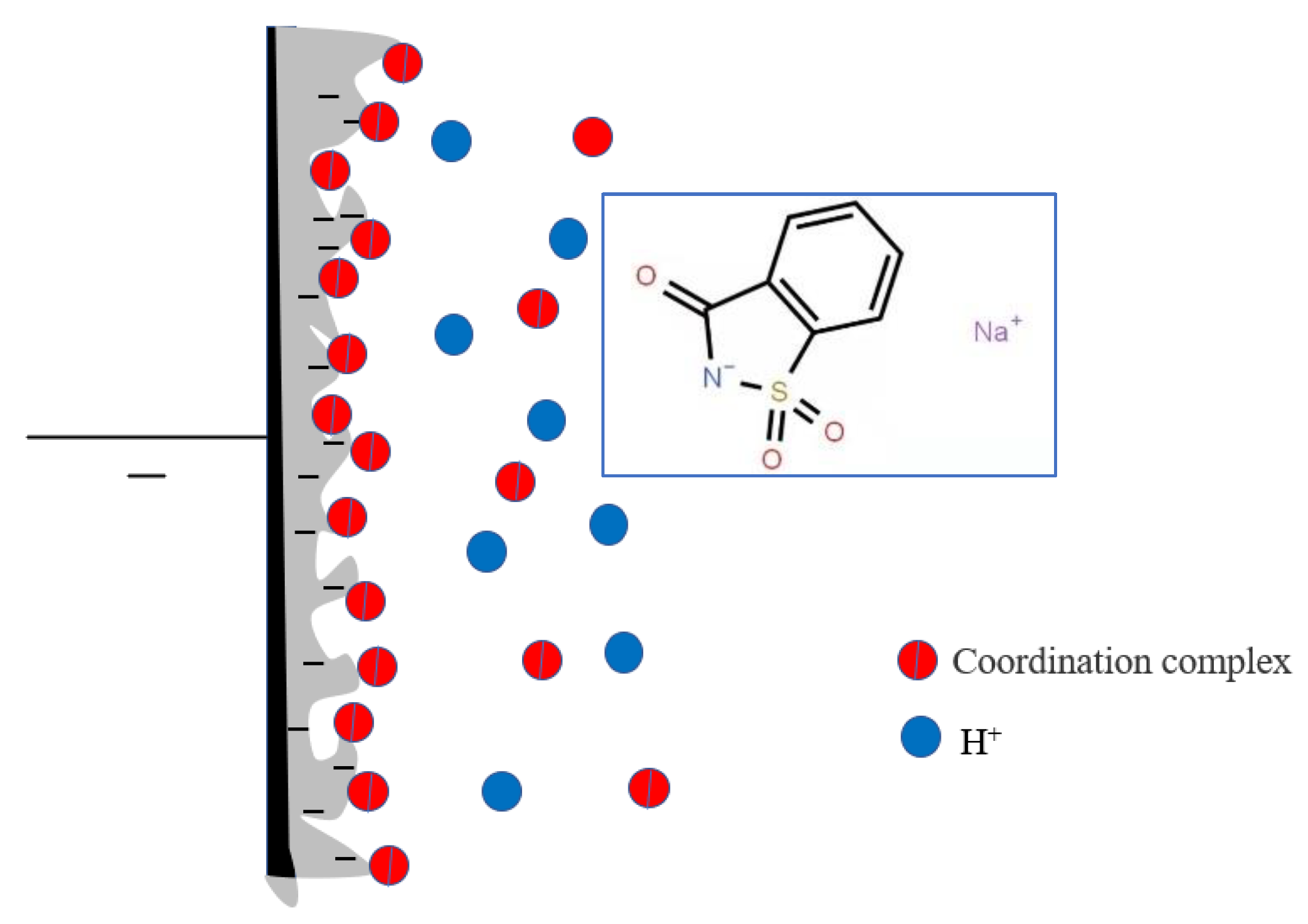
4. The Mechanism of Saccharin Sodium

Saccharin sodium is a sulfamic acid compound with both coordination ability and surface activity. The structure of saccharin sodium is shown in Figure 11. Saccharin sodium contains two hydrophilic groups (carbonyl and amine), one hydrophobic group (benzene ring with strong hydrophobicity) and one sulfinyl. Saccharin sodium is more active in aqueous solution because the ratio of the hydrophobic and hydrophilic. In addition, the presence of sulfinyl groups also determines that saccharin sodium has the characteristics of high polarity, good thermal stability, and good solubility. Therefore, saccharin sodium can be adsorbed directly on the electrode. At this point, the hydrophobic group with less free energy replaces the water molecules and is arranged on the interface. Fe2+ and H+ are in a competitive relation on the hydrophilic group of saccharin sodium, but Fe2+ features a lone-pair electron on the 3d orbital, making Fe2+ more effective at adsorbing amino groups of saccharin sodium than H+. Furthermore, Fe2+ forms a coordination complex with the amino group of saccharin sodium, which adsorbs on the electrode surface. The positively charged coordination complex prevents H+ from approaching the cathode, and increases the activation energy of the hydrogen discharge, thereby reducing the level of hydrogen evolution and improving the internal stress of the coating. In this process, the coordination complexes absorb and discharge at a higher current and make the cathode current evenly distributed. Therefore, saccharin sodium also levels, brightens, and expands the range of current density. In addition, saccharin sodium decreases the amount of hydrogen deposited, so the amount of hydrogen permeation in the coating is reduced, thereby improving the cathode’s current efficiency and reducing the fragility of the coating.

5. Conclusions

In summary, the method of stepwise increasing current density was used, and the results showed that saccharin sodium can significantly reduce the internal stress of iron-nickel magnetic films. The mechanism of the saccharin sodium was explored by a series of investigations. Firstly, the electrochemical workstation was used to measure the polarization curves of Fe2+, Ni2+, and the co-deposition process. The results showed that increases in the pH value (within a certain range) inhibited the deposition process of Fe2+ and Ni2+. The system was relatively stable when the pH value was 2, with a smaller number of surface bubbles indicating that the hydrogen evolution was relatively small. Secondly, the temperature had a greater impact on the iron-nickel co-deposition process. The experiments showed that the increase of temperature promoted the co-deposition process because the diffusion speed of the Fe2+ and Ni2+ are increased. Thirdly, the curling angle θ of the iron-nickel magnetic film was set to represent the magnitude of the internal stress. The measurement results showed that the curling angle θ was reduced by 40° when the concentration of the saccharin sodium was 2 g/L (compared with no addition of saccharin sodium). The results mean that sodium saccharin can significantly reduce the internal stress of Fe-Ni magnetic film, which in turn reduces the brittleness and expands the application of iron-nickel magnetic film. Finally, we explored the mechanism of the saccharin sodium. This research will help to promote the development of new stress-reducing agents and apply saccharin sodium in a wider range to deal with the manufacturing problems posed by soft magnetic materials.

Author Contributions

Conceptualization, W.W. and Y.W.; methodology, W.W.; software, Y.W.; validation, Y.W., B.J. and W.W.; formal analysis, Y.W.; investigation, Y.W.; resources, B.J.; data curation, Y.W.; writing—original draft preparation, Y.W.; writing—review and editing, Y.W.; visualization, Y.W.; supervision, W.W.; project administration, W.W.; funding acquisition, W.W. All authors have read and agreed to the published version of the manuscript.

Funding

This research received no external funding.

Institutional Review Board Statement

Not applicable.

Informed Consent Statement

Not applicable.

Conflicts of Interest

The authors declare no conflict of interest.

References

  1. Krings, A.; Boglietti, A.; Cavagnino, A.; Sprague, S. Soft magnetic ferrite core blank material conveying device. IEEE Trans. Ind. Electron. 2017, 64, 2405–2414. [Google Scholar] [CrossRef]
  2. Bhattacharya, S. Transforming the transformer. IEEE Spectr. 2017, 54, 38–43. [Google Scholar] [CrossRef]
  3. Krishnamurthy, S. Simplified loss analysis for high speed SiC MOSFET inverter. In Proceedings of the Electronics Conference and Exposition (APEC, IEEE), East Hartford, CT, USA, 12 June 2012; pp. 1414–1417. [Google Scholar]
  4. Kroposki, B. Benefits of Power Electronic Interfaces for Distributed Energy Systems. IEEE Trans. Energy Convers. 2010, 25, 901–908. [Google Scholar] [CrossRef] [Green Version]
  5. Bose, B.K. Global Warming: Energy, Environmental Pollution, and the Impact of Power Electronics. IEEE Ind. Electron. Mag. 2010, 4, 6–17. [Google Scholar] [CrossRef]
  6. Waide, P.; Brunner, C.U. Energy-Efficiency Policy Opportunities for Electric Motor-Driven Systems; International Energy Agency (IEA): IEA Energy Papers: Paris, France, 2011. [Google Scholar]
  7. Popović-Gerber, J. Power Electronics Enabling Efficient Energy Usage: Energy Savings Potential and Technological Challenges. IEEE Trans. Power Electron. 2012, 27, 2338–2353. [Google Scholar] [CrossRef]
  8. Ahn, S.H.; Choi, I.; Park, H.-Y.; Hwang, S.J.; Yoo, S.J.; Cho, E.; Kim, H.-J.; Henkensmeier, D.; Nam, S.W.; Kim, S.-K. Effect of morphology of electrodeposited Ni catalysts on the behavior of bubbles generated during the oxygen evolution reaction in alkaline water electrolysis. Chem. Commun. 2013, 49, 9323–9325. [Google Scholar] [CrossRef]
  9. Lu, X.; Zhao, C. Electrodeposition of hierarchically structured threedimensional nickeleiron electrodes for efficient oxygen evolution at high current densities. Nat. Commun. 2015, 6, 6616. [Google Scholar] [CrossRef] [Green Version]
  10. Vicenzo, A. Structure and mechanical properties of electrodeposited nanocrystalline Ni-Fe alloys. J. Electrochem. Soc. 2013, 160, D570–D577. [Google Scholar] [CrossRef]
  11. Sohrabi, A.; Dolati, A.; Ghorbani, M.; Monfared, A.; Stroeve, P. Nanomechanical properties of functionally graded composite coatings: Electrodeposited nickel dispersions containing silicon micro-and nanoparticles. Mater. Chem. Phys. 2010, 121, 497–505. [Google Scholar] [CrossRef]
  12. Balachandran, R.; Yow, H.; Ong, B.; Tan, K.B.; Anuar, K.; Wong, H. Surface morphology and electrical properties of pulse electrodeposition of NiFe films on copper substrates in ultrasonic field. Int. J. Electrochem. Sci. 2011, 6, 3564–3579. [Google Scholar]
  13. Abdel-Karim, R.; Reda, Y.; Muhammed, M.; El-Raghy, S.; Shoeib, M.; Ahmed, H.J. Electrodeposition and characterization of nanocrystalline Ni-Fe alloys. Nanomaterials 2011, 10, 8. [Google Scholar] [CrossRef]
  14. Liang, D.; Liu, J.; Reuter, K.; Baker-O’Neal, B.; Huang, Q. Electroplating of Fe-Rich NiFe alloys in Sub-50 nm lines. J. Electrochem. Soc. 2014, 161, D301–D308. [Google Scholar] [CrossRef]
  15. Cao, Y.; Wei, G.; Ge, H.; Meng, X. Study on preparation of NiFe films by galvanostatic electrodeposition. Surf. Eng. 2014, 30, 97–101. [Google Scholar] [CrossRef]
  16. Gong, J.; Riemer, S.; Kautzky, M.; Tabakovic, I. Composition gradient, structure, stress, roughness and magnetic properties of 5–500 nm thin NiFe films obtained by electrodeposition. J. Magn. Magn. Mater. 2016, 398, 64–69. [Google Scholar] [CrossRef]
  17. Dragos, O.; Chiriac, H.; Lupu, N.; Grigoras, M.; Tabakovic, I. Anomalous codeposition of fcc NiFe nanowires with 5–55% Fe and their morphology, crystal structure and magnetic properties. J. Electrochem. Soc. 2016, 163, D83–D94. [Google Scholar] [CrossRef]
  18. Luo, Q.; Peng, M.; Sun, X.; Luo, Y.; Asiri, A.M. Efficient electrochemical water splitting catalyzed by electrodeposited NiFe nanosheets film. Int. J. Hydrogen Energy 2016, 41, 8785–8792. [Google Scholar] [CrossRef]
  19. Kim, K.H.; Zheng, J.Y.; Shin, W.; Kang, Y.S. Preparation of dendritic NiFe films by electrodeposition for oxygen evolution. RSC Adv. 2012, 2, 4759–4767. [Google Scholar] [CrossRef]
  20. Kuru, H.; Kockar, H.; Alper, M.; Karaagac, O. Growth of binary NieFe films: Characterisations at low and high potential levels. J. Magn. Magn. Mater. 2015, 377, 59–64. [Google Scholar] [CrossRef]
  21. Wei-Su, C.; Yang, W.; Jun-Ming, G.; Feng-Jiao, H. Thermal stability of Ni-Fe alloy foils continuously electrodeposited in a fluorborate bath. Open J. Metal 2012, 2, 18–23. [Google Scholar]
  22. Torabinejad, V.; Rouhaghdam, A.S.; Aliofkhazraei, M.; Allahyarzadeh, M. Electrodeposition of NieFe and NieFe-(nano Al2O3) multilayer coatings. J. Alloys Compd. 2016, 657, 526–536. [Google Scholar] [CrossRef]
  23. Van Petegem, S.; Zimmermann, J.; Van Swygenhoven, H. Microstructure and deformation mechanisms in nanocrystalline NieFe. Part II. In situ testing during X-ray diffraction. Acta Mater. 2013, 61, 5846–5856. [Google Scholar] [CrossRef]
  24. Tabakovic, I.; Inturi, V.; Thurn, J.; Kief, M. Properties of Ni1_xFex (0.1 <x <0.9) and Invar (x¼0.64) alloys obtained by electrodeposition. Electrochim. Acta 2010, 55, 6749–6754. [Google Scholar]
  25. Deepthi, K.A.; Balachandran, R.; Ong, B.H.; Tan, K.B.; Wong, H.Y.; Yow, H.K.; Srimala, S. Physical and electrical characteristics of NiFe thin films using ultrasonic assisted pulse electrodeposition. Appl. Surf. Sci. 2016, 360, 519–524. [Google Scholar] [CrossRef]
  26. Ohta, M.; Yoshizawa, Y.J. Recent Progress in Fe-based nanocrystalline soft magnetic alloys and their applications. Phys. D Appl. Phys. 2011, 44, 064004. [Google Scholar] [CrossRef]
  27. Kong, F.; Men, H.; Liu, T.; Shen, B. Research progress and application prospects of Fe-based soft magnetic amorphous/nanocrystalline alloys. J. Appl. Phys. 2012, 111, 07A311. [Google Scholar] [CrossRef]
  28. Fan, X.; Men, H.; Ma, A.; Shen, B. Soft magnetic properties in Fe84-xB10C6Cux nanocrystalline alloys. J. Magn. Magn. Mater. 2013, 326, 22. [Google Scholar] [CrossRef]
  29. Xiang, Z.; Wang, A.; Zhao, C.; Men, H.; Wang, X.; Chang, C. The solubility of cerium in La2Ti2O7 by DFT + U calculations. J. Alloys Compd. 2015, 622, 1000. [Google Scholar] [CrossRef]
  30. Sharma, P.; Zhang, X.; Zhang, Y.; Makino, A. Competition driven nanocrystallization in high Bs and low coreloss Fe–Si–B–P–Cu soft magnetic alloys. Scr. Mater. 2015, 95, 3. [Google Scholar] [CrossRef]
  31. Jafari, S.; Beitollahi, A.; Yekta, B.E.; Ohkubo, T.; Sky, V.B.; Marsilius, M.; Herzer, G.; Hono, K. Atom probe analysis and magnetic properties of nanocrystalline Fe84.3Si4B8P3Cu0.7. J. Alloys Compd. 2015, 674, 136. [Google Scholar] [CrossRef]
  32. Suzuki, K.; Parsons, R.; Zang, B.; Onodera, K.; Kishimoto, H. Copper-free nanocrystalline soft magnetic materials with high saturation magnetization comparable to that of Si steel. Appl. Phys. Lett. 2017, 110, 012407. [Google Scholar] [CrossRef]
  33. Hasegawa, R.; Chien, C.L. Mössbauer and its r.f. sideband effects in iron-rich glassy alloys. Solid State Commun. 1976, 18, 913. [Google Scholar] [CrossRef]
  34. Pathak, S.; Guinard, M.; Vernooij, M.G.C.; Cousin, B.; Wang, Z.; Michler, J.; Philippe, L. Influence of lower current densities on the residual stress and structure of thick nickel electrodeposits. Surf. Coat. Technol. 2011, 205, 3651–3657. [Google Scholar] [CrossRef]
  35. Ortolani, M.; Zanella, C.; Ricardo, C.L.A.; Scardi, P. Elastic grain interaction in electrodeposited nanocomposite nickel matrix coatings. Surf. Coat. Technol. 2012, 206, 2499–2505. [Google Scholar] [CrossRef]
  36. Vazquez, J.A.; Altamirano, L.G.; Pritzker, M.; Luna, R.S.; Cabrera, R.S. Experimental and modeling study of nickel electrodeposition including H+ and water reduction and homogeneous reactions. J. Electrochem. Soc. 2011, 158, D33–D41. [Google Scholar] [CrossRef]
  37. Xie, L.S.; Li, J.S.; Zhang, T.B.; Kou, H.C. Role of milling time and Ni content on dehydrogenation behavior of MgH2/Ni composite. Trans. Nonferr. Met. Soc. China 2017, 27, 569–577. [Google Scholar] [CrossRef]
  38. Dundálek, J.; Šnajdr, I.; Libánský, O.; Vrána, J. Zinc electrodeposition from flowing alkaline zincate solutions: Role of hydrogen evolution reaction. J. Power Sources 2017, 372, 221–226. [Google Scholar] [CrossRef]
  39. Hong, B.; Yu, X.Y.; Jiang, L.X.; Xue, H.T.; Liu, F.Y.; Liu, J.; Liu, Y.X. Hydrogen evolution inhibition with diethylenetriamine modification of activated carbon for a lead-acid battery. RSC Adv. 2014, 4, 33574–33577. [Google Scholar] [CrossRef]
  40. Liu, X.; Evans, P.; Zangari, G. Electrodeposited Co-Fe and Co-Fe-Ni alloy films for magnetic recording write heads. IEEE Trans. Magn. 2000, 36, 3479–3481. [Google Scholar]
  41. Djokic, S.S. Electrodeposition: Theory and Practice; Springer Science & Business Media: Berlin, Germany, 2010. [Google Scholar]
  42. Boudinar, S.; Benbrahim, N.; Benfedda, B.; Kadri, A.; Chainet, E.; Hamadou, L. Electrodeposition of heterogeneous Mn−Bi thin films from a sulfate−nitrate bath: Nucleation mechanism and morphology. J. Electrochem. Soc. 2014, 161, D227–D234. [Google Scholar] [CrossRef]
  43. Mockute, D.; Butkiene, R.; Nivinskiene, O. Effect of chloride ions on the behavior of saccharin, N-methylsaccharin, and 2-butyne-1,4-diol during electrodeposition of nickel from acid electrolytes. Russ. J. Electrochem. 2001, 37, 376–381. [Google Scholar] [CrossRef]
  44. Lukomska, A.; Sobkowski, J. Potential of zero charge of monocrystalline copper electrodes in perchlorate solutions. J. Electroanal. Chem. 2004, 567, 95–102. [Google Scholar] [CrossRef]
  45. Bhandari, A.; Hearne, S.J.; Sheldon, B.W.; Soni, S.K. Microstructural origins of saccharin-induced stress reduction in electrodeposited Ni. J. Electrochem. Soc. 2009, 156, D279–D282. [Google Scholar] [CrossRef]
  46. Lallemand, F.; Ricq, L.; Wery, A.; Bercot, P. The influence of organic additives on the electrodeposition of irongroup metals and binary alloy from sulfate electrolyte. Appl. Surf. Sci. 2004, 228, 326–333. [Google Scholar] [CrossRef]
  47. Hassani, S.; Raeissi, K.; Golozar, M.A. Effects of saccharin on the electrodeposition of Ni-Co nanocrystalline coatings. J. Appl. Electrochem. 2008, 38, 689–694. [Google Scholar] [CrossRef]
Figure 1. Effect of pH value on the deposition of Fe2+. T = 30 °C.
Processes 09 01883 g001
Figure 2. Effect of pH value on deposition process of Ni2+. T = 30 °C.
Processes 09 01883 g002
Figure 3. Effect of pH value on the Fe–Ni co-deposition process. T = 30 °C.
Processes 09 01883 g003
Figure 4. Effect of temperature on the Fe–Ni co-deposition process. pH = 2.
Processes 09 01883 g004
Figure 5. Effect of C7H5NO3SNa on deposition process of Fe2+. pH = 2, T = 30 °C.
Processes 09 01883 g005
Figure 6. Effect of C7H5NO3SNa on deposition process of Ni2+. pH = 2, T = 30 °C.
Processes 09 01883 g006
Figure 7. Effect of C7H5NO3SNa on Fe–Ni co-deposition process. pH = 2, T = 30 °C.
Processes 09 01883 g007
Figure 8. Effect of C7H5NO3SNa on the rolling angle (θ) of Fe-Ni magnetic film. pH = 2, 30 °C.
Processes 09 01883 g008
Figure 9. The effect of saccharin sodium on the surface morphology. (a) without saccharin sodium, (b) with saccharin sodium.
Processes 09 01883 g009
Figure 10. Crystal structure of iron-nickel alloy with saccharin sodium.
Processes 09 01883 g010
Figure 11. The structure of the complex of saccharin sodium and Fe2+ at the electrode/solution interface.
Processes 09 01883 g011
Publisher’s Note: MDPI stays neutral with regard to jurisdictional claims in published maps and institutional affiliations.

