Article

Design and Experiment of a Multi-Row Spiral Quantitative Fertilizer Distributor

1
Henan Province Engineering Research Center of Ultrasonic Technology Application, Pingdingshan University, Pingdingshan 467000, China
2
Jinan Heavy Industry Engineering Co., Ltd., Jinan 250000, China
*
Author to whom correspondence should be addressed.
Processes 2025, 13(7), 1992; https://doi.org/10.3390/pr13071992
Submission received: 27 May 2025 / Revised: 19 June 2025 / Accepted: 21 June 2025 / Published: 24 June 2025
(This article belongs to the Section Particle Processes)

Abstract

Aiming at the existing fertilizer distributor’s lack of stability of fertilizer discharge and uniformity of fertilizer discharge, which affects the precise application of fertilizer, a design and testing of a multi-row spiral quantitative fertilizer distributor was designed. The design principle and working principle of the fertilizer distributor are described, and the parameter ranges of centrifugal cone discs’ cone angle, cone disc inclination, cone disc rotation speed, etc., are determined. The Elementary Discrete Element Method (Referred to as EDEM in the following) simulation analysis software was adopted to carry out the simulation analysis of the fertilizer discharge process of the fertilizer discharger, to study the influence of each parameter on the fertilizer discharge performance and the optimal combination parameters of the fertilizer discharger. Taking the coefficient of variation for the consistency of fertilizer application amount among rows and the coefficient of variation for the consistency of fertilizer application amount within the same row as the evaluation indicators, and taking the cone angle of the centrifugal cone disk, the cone disk inclination angle, and the cone disk rotational speed as the test factors, multi-factor and multi-level experiments were carried out. The simulation test results show that the optimal parameter combination of the fertilizer discharger is the rotational speed of the centrifugal cone disk at 95 r/min, the cone angle of the cone disk at 16.7°, and the blade inclination angle of the cone disk at 2.7°. Using potassium sulphate compound fertilizer as the test material, the bench test on the fertilizer discharge performance and adaptability of the fertilizer distributor when the speed of centrifugal cone discs was 30~110 r/min was carried out to verify the fertilizer discharge performance of the fertilizer distributor. The results of the validation test showed that the coefficient of variation for the consistency of fertilizer application amount among rows of fertilizer distributor at different rotational speeds was lower than 4.25%, the coefficient of variation for the consistency of fertilizer application amount within the same row was lower than 3.21%, which meets the requirement of fertilizer discharge quality. The research provides technical support for enhancing the performance of fertilizer distributors and achieving precise fertilizer application, thereby playing an active role in improving fertilization efficiency and promoting sustainable agricultural development.

1. Introduction

As one of the most important basic substances in agricultural production, chemical fertilizers play a significant role in ensuring efficient agricultural production. China is the world’s largest user of chemical fertilizers [1]. In 2024, China’s chemical fertilizer output was 60.061 million tons (in pure terms), accounting for approximately 29% of the global total. This means that China’s fertilizer supply is of great significance in meeting the global demand for increased food production [2], and the growth trend of future food demand will gradually increase [3]. Rational application of fertilizer and improvement of fertilizer utilization are important ways to reduce environmental pollution and lower the cost of agricultural production as well as to increase food [4]. Quantitative and uniform mechanized fertilizer application is an important way to solve the problem of pollution faced by agriculture [5], and is the direction of development to reduce the amount of fertilizer applied and improve fertilizer utilization.
In recent years, important progress has been made both at home and abroad in the field of fertilizer distributor design, which has supported the development of agricultural mechanization [6,7,8,9,10]. Li Han et al. designed a spiral winch discharge-type fertilizer application device for oil tea forests to adapt to the fertilizer demand of oil tea forests, and optimized the parameters of the fertilizer distributor through discrete element simulation and carried out experimental verification [11]; Ton et al. designed a new type of fertilizer distributor using the principle of fertilizer full filling spiral extrusion-type conveying, and the influence of the inclination angle of the discharging mouth on the uniformity of discharging fertilizer was derived from the experimental analysis [12]; Sui Xiaobin et al. developed a two-row equal-volume fertilizer truck for granular organic fertilizer in blueberry plantations to ensure uniform fertilizer application to blueberries, and carried out overall design, component selection, and related performance analysis of the fertilizer truck [13]; Xu Wenzhi et al. designed a four-head tilting spiral precision fertilizer distributor to achieve stability of fertilizer delivery [14]; Zhang Xiuli et al. designed a device for the proportional mixing of tobacco granular fertilizer, which was able to achieve efficient and uniform application of herb granular fertilizer [15]; Xu Chunbao et al. designed a centrifugal chamber disc extrusion-type high-speed precision fertilizer distributor for oilseed rape to reduce fertilizer particle fragmentation and meet the high-speed direct seeding operation of oilseed rape [16]; Shi Jianwei et al. optimized the design of a fertilizer distributor for a substrate-mulching no-tillage planter to carry out experimental research on the effect of substrate-mulching no-tillage seeding technology on red soil respiration and maize growth and yield [17]. Research on fertilizer application technology began as early as 1800 abroad, and the technologies in precise variable fertilization technology and intelligent fertilization systems are relatively mature. Shi Yinyan et al. mainly conducted numerical simulation research on the spreading performance and distribution pattern of centrifugal variable-rate fertilizer applicators based on discrete element method (DEM) software [18]. Foreign fertilizer application technology research is still early and the technology is very mature [19]. The towed high-clearance ground single-shaft fertilizer applicator produced by Salford, USA can meet the harsh working conditions such as complex terrain, damp environment, and bad weather [20]. Fertilizer spreader is a key component of fertilizer distributors, and at present, there are mainly centrifugal discs, grooved wheels, spirals, and vibrating types of fertilizer spreaders [21]. Despite the fruitful achievements in the field of fertilizer spreader design, the existing fertilizer spreaders still have problems such as poor accuracy and uniformity of fertilizer spreading [22].
This paper aims to improve the uniformity and stability of the discharge volume of the fertilizer discharger and designs a multi-row spiral quantitative fertilizer discharger with precise and controllable discharge volume. Through theoretical analysis and analysis of the fertilizer discharge process, the key parameters that affect the fertilizer discharge performance are determined. Then, the EDEM 2022 simulation software is used to carry out the fertilizer discharge process test to determine the optimal structural parameters of the fertilizer discharge device. Finally, the fertilizer discharge performance of the fertilizer discharger is verified through bench tests, providing a foundation for the structural optimization and performance improvement of the fertilizer discharger.

2. Materials and Methods

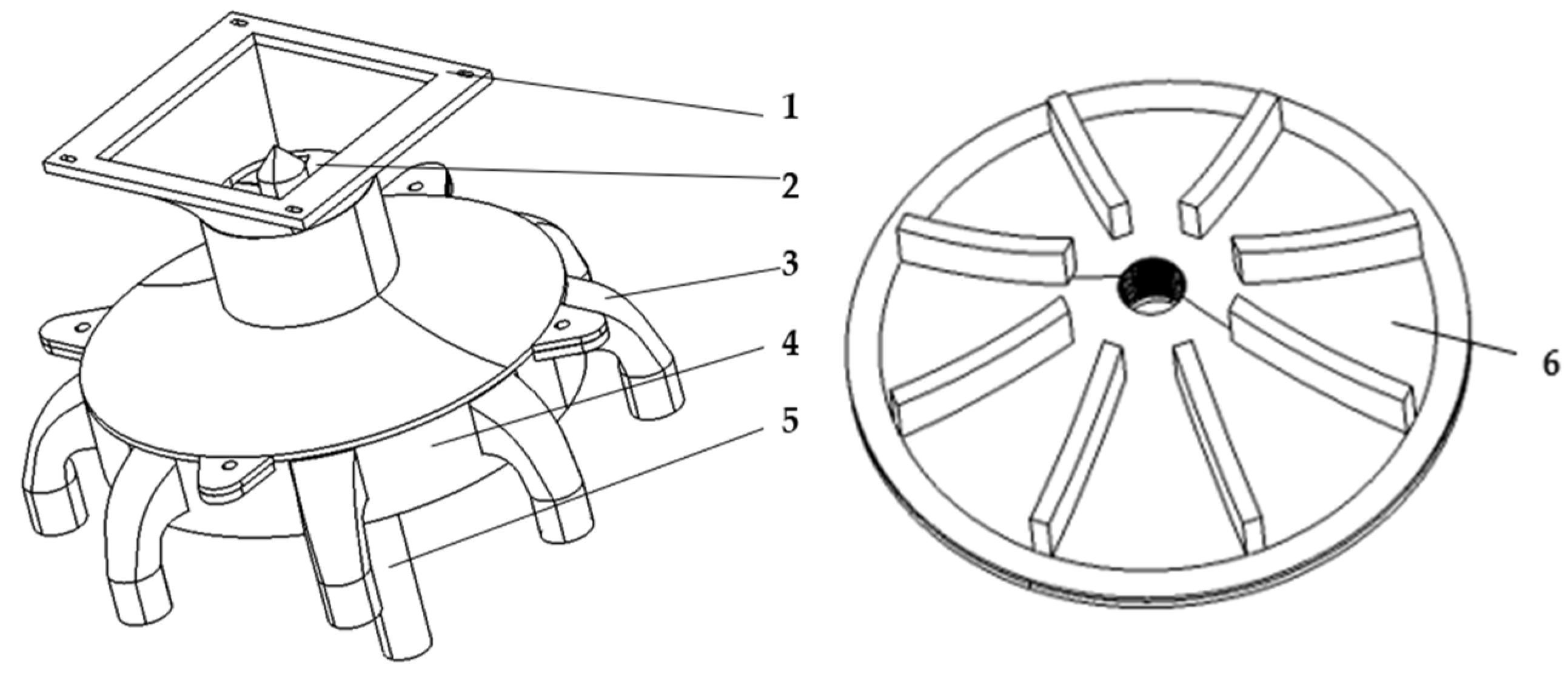
2.1. Fertilizer Distributor Structure and Working Principle

The design and testing of a multi-row spiral quantitative fertilizer distributor is shown in Figure 1, and its main components include the upper shell, the spiral quantitative fertilizer feeder, the centrifugal cone discs, the fertilizer guide tube, and the lower shell. To meet the varying fertilizer application requirements across different scenarios, the fertilizer spreader innovatively combines a spiral quantitative fertilizer discharge structure with centrifugal fertilizer spreading principles, integrating precise fertilizer application control with uniform distribution. Its core components include the spiral blades at the top, the centrifugal cone disc in the middle, and eight evenly distributed fertilizer nozzles on the lower housing. These structures work in tandem to lay the foundation for efficient and precise fertilizer application.
During operation, fertilizer particles are quantitatively transported toward the centrifugal cone disc by the top spiral blades. Subsequently, the fertilizer moves through the upper surface of the rotating centrifugal cone disc based on the centrifugal spreading principle. Due to the action of the upper housing, the fertilizer rapidly and uniformly moves toward the edge of the centrifugal cone disc within the region formed by the housing and the centrifugal cone disc, without being scattered outward, and enters the fertilizer nozzle inlet. Ultimately, the fertilizer is discharged through the eight fertilizer discharge nozzle outlets, enabling simultaneous fertilizer distribution across eight rows. Throughout the process, the spiral blades ensure precise fertilizer output, while the centrifugal cone disc and fertilizer discharge nozzles ensure uniform fertilizer distribution across all rows, fully meeting the precise fertilizer application requirements of diverse scenarios.

2.2. Fertilizer Distributor Key Parameters Design and Analysis

2.2.1. Parameter Design of the Fertilizer Dosing Mechanism

In order to prevent ‘arching’ of the fertilizer particles inside the fertilizer distributor or uneven discharge, a guiding cone has been added above the auger unit. This structure is mainly responsible for guiding the fertilizer particles and has a smooth, conical surface in order to enhance the contact with the fertilizer particles and to reduce the problem of fertilizer damage caused by mechanical rotation, as shown in Figure 2.
θ Z 180 2 ψ
where θz is the top angle of the broken arch cone, °; ψ is the natural angle of repose of the fertilizer particles, °.
According to the physical properties of fertilizer particles, its natural angle of repose is 25.6°. To meet the requirements of arch breaking, the top angle of arch-breaking cone is θz ≤ 128.8°. Based on the overall mechanism of fertilizer distributor and considering the friction and extrusion of fertilizer particles, the cone top angle θz is selected as 60°.
L Z = D i
where Lz is the length of the cross-section side of the arch-breaking cone, mm; Di is the inner diameter of the screw gibbet device, mm.
It can be calculated that the width of the spiral blade is 3 mm < L < 9 mm, the static friction coefficient is 0.2, and the size of the helical wire guide P1 needs to meet the size of P1 ≤ 32 mm. Combining various factors, it is finally determined that the helical wire guide P1 is 32 mm.
By consulting the Handbook of Agricultural Machinery Design 2007 edition [23], it is known that the fertilizer discharge rate of the screw winch unit of the fertilizer distributor is
R n = π D 2 D i 2 2400 B v n λ ρ n i P 1 K
where B is the working width of fertilizer distributor, m; vn is the working rate of fertilizer distributor, m/s; D is the outer diameter of the spiral winch, mm; λ is the filling coefficient of the fertilizer particles, taken as 0.5; ρ is the density of the fertilizer particles, taken as 1060 g/L; ni is the rotational speed of the spiral fertilizer feed bar, r/s; P1 is the spiral lead, mm; K is the correction coefficient of inclined conveying of the spiral device.
When the axial distance P1 between the corresponding points of two adjacent revolutions of the spiral blades is kept constant, the rotational speed of the spiral winch device can be adjusted by increasing the outer diameter D of the spiral or decreasing the inner diameter Di of the spiral. Increasing the spiral outer diameter D will correspondingly increase the size of the fertilizer supply sleeve, which will also cause changes in the overall specifications of the fertilizer discharge device. While reducing the spiral inner diameter Di, although it can reduce the speed, it will produce more torque, reducing the reliability of the device. A comprehensive analysis can be obtained. The spiral blade outer diameter D ≥ 60 mm, taking into account its symmetry.
According to Agricultural Machinery Design Manual, 8 rows of fertilizer distributor can meet the working width of 2~3.6 m, and the working rate of 4~10 km/h implements operating requirements. This paper is based on the working width of 2 m, and the working rate of 4 km/h as the basis of the design calculation. The screw device inclined conveying correction coefficient is related to the degree of inclination of the screw device and the design of the screw winch device for the vertical way, and the inclined conveying correction coefficient K is 0.36. Combined with the analysis of the above content, it can be concluded that the screw winch device speed is as low as 28.78 r/min; in order to meet the requirements of the amount of fertilizer discharged, the speed will be set at a minimum of 30 r/min.

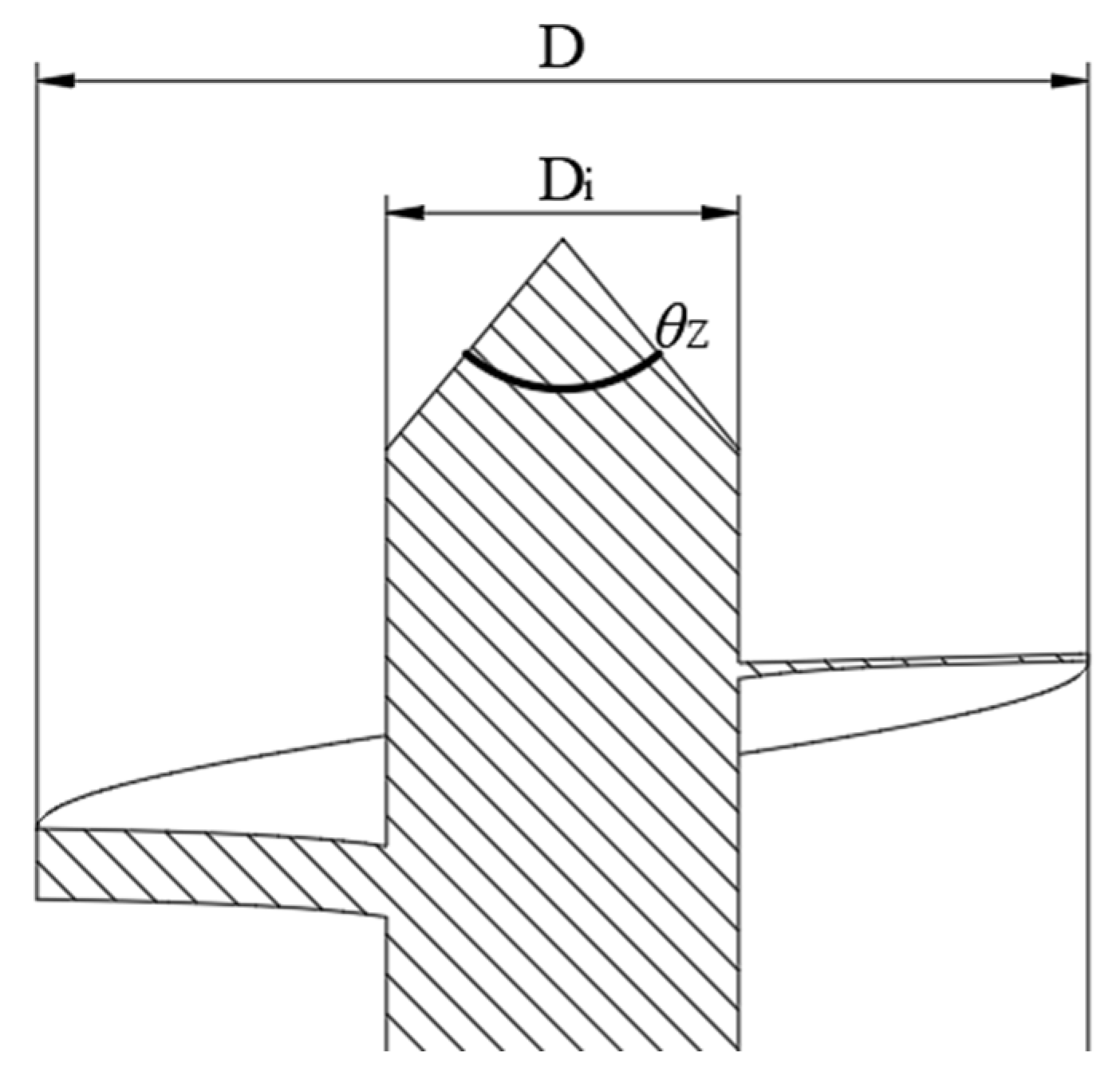
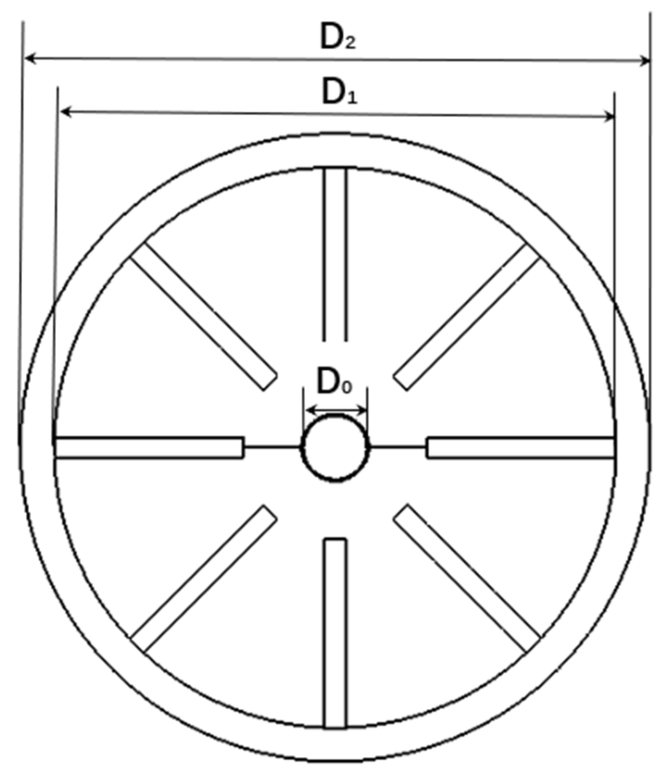
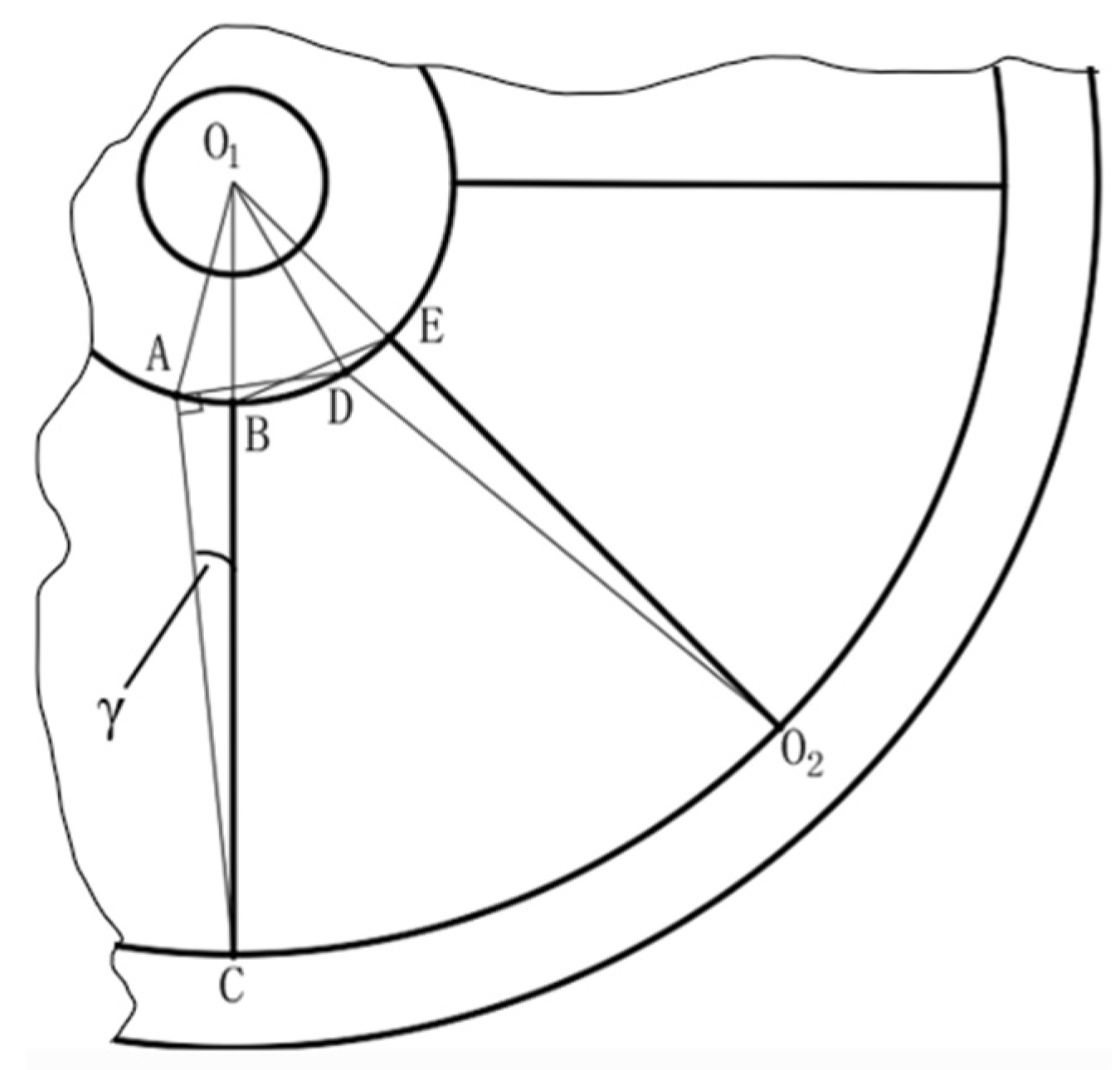
2.2.2. Centrifugal Cone Disc Parameter Design

The centrifugal disc is the core component of the fertilizer distributor and is surrounded by a vane structure on the cone surface. The angle of the centrifugal disc determines whether the fertilizer particles disperse smoothly on the conical surface and enter uniformly into the 8 fertilizer guiding tubes in the lower housing.
The size of the centrifugal disc diameter directly affects the movement of the fertilizer and the movement time into the guide tube. Considering the overall structure of the fertilizer distributor, the centrifugal conical disc of the fertilizer distributor has a large diameter D2 of 185 mm and a small diameter D1 of 170 mm, as shown in Figure 3. The middle and upper part of the cone disc is set as a threaded hole structure, in order to be closely matched with the shaft of the screw winch device, which is 20 mm for D0 = Di.
In order to ensure that the fertilizer particles are quickly transported to the edge of the centrifugal cone disc, a cone disc blade with a certain radial deflection angle γ is set up, as shown in Figure 4, and the tilted cone disc blade is approximated to be AC and DO2. When AD = BE, ∠CAD = 90°, the circulation area between the cone disc blades of the fertilizer distributor can be guaranteed to be the same as that of the cone disc blade when the cone disc blade is not tilted. According to the structure of fertilizer distributor, O1C is 85 mm, AD is 20 mm, and O1A and O1D are both 25 mm, according to the triangle sine-cosine theorem:
O 1 D 2 = AO 1 2 + AD 2 2 AO 1 AD cos O 1 AD
O 1 C 2 = AO 1 2 + AC 2 2 AO 1 AC cos O 1 AC
O 1 AD = arccos ( cos O 1 AD )
O 1 A sin ACO 1 = O 1 C sin O 1 AC
It can be obtained that ∠ACO1 is 6.76°, γ = 6.76°. Due to the existence of a certain rotational speed of the centrifugal cone disc itself, fertilizer particles fall into the rotating centrifugal cone disc, and even if the centrifugal cone disc inclination angle is 0, fertilizer particles will rotate with the cone disc and thus enter the fertilizer guide tube. Therefore, after comprehensive consideration, the centrifugal cone disc blade inclination angle γ value range is 0°~6.8°.
The centrifugal cone disc is also set with a certain inclination angle, when the fertilizer particles move to the cone disc after the free fall, its inclination angle must be greater than the angle of repose of the fertilizer particles. According to the principle that the free fall of fertilizer needs to be greater than the angle of repose, according to the previous analysis, the inclination angle φ of the centrifugal cone disc is 25.6°, and its local section is shown in Figure 5. When the cone disc inclination angle is greater than the angle of repose, the fertilizer particles can fall into the centrifugal cone disc freely, so the maximum inclination angle is set to 25.6°. Due to the existence of the centrifugal cone disc rotation, when the cone disc inclination angle is less than the angle of repose, the fertilizer distributor can still rely on the rotating centrifugal cone disc generated by the centrifugal force of the fertilizer discharging. In summary, the centrifugal disc inclination angle can be set from 0° to 25.6°.

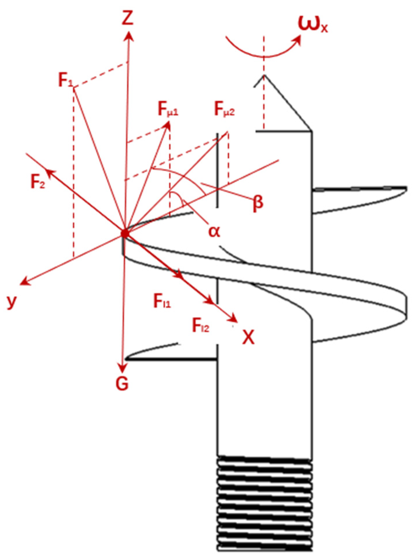
2.2.3. Motion Analysis of Fertilizer Supply Processes

The screw winch relies on the relative motion of the screw blades and the fertilizer particles to complete the quantitative and stable conveying, and when the screw blades rotate, a friction force Fμ1 will be generated, which will push the fertilizer particles to rotate. When the screw winch device is running, the fertilizer micro-element is subject to centrifugal force Fl; it will move along the wall of the screw winch device, which will produce friction with the outer fertilizer micro-element, forming friction force Fμ2, and at the same time, there is also the influence of its own gravity G of the fertilizer micro-element, which will reach the state of force equilibrium under the joint action of these forces. In order to study its motion law in depth, the fertilizer micro-element is selected to construct the space motion reference system and carry out the dynamics analysis, as shown in Figure 6.
Using the method of relative motion mechanics of plasmas, the basic expression for the dynamics of fertilizer particle micro-elements is established as
m a r = F l 1 + F l 2 + F
F l 1 = m r ω x 2 F l 2 = 2 m r ω x ω x ω r
F l 2 = 2 m r ω x ω x ω r
F μ 1 = μ 1 F 1
F 1 = G 1 F l 1 sin α e
F μ 2 = μ 2 F 2
G 1 = m g
α e = arctan P 1 π D
where m is the mass of fertilizer micro-element, kg; ar is the relative acceleration of fertilizer micro-element, m/s2; Fl1 is the centrifugal force of fertilizer micro-element, N; Fl2 is the inertia force of fertilizer micro-element, N; F is the combined force of external forces on fertilizer micro-element, N; r is the radius of fertilizer micro-element, mm; ωx is the angular velocity of screw winch device, rad/s; ωr is the relative angular velocity of fertilizer micro-element and screw winch device, N rad/s; F1 is the support reaction force of the spiral blade on the fertilizer micro-element, N; F2 is the support reaction force of the outer fertilizer on the fertilizer micro-element, N; Fμ1 is the friction force of the spiral blade on the fertilizer micro-element, N; Fμ2 is the friction force of the outer fertilizer on the fertilizer micro-element, N; μ1 is the friction coefficient between the spiral blade and the fertilizer particles, 0.2; μ2 is the coefficient of internal friction of the fertilizer particle group, 0.5; G is the gravitational force of fertilizer micro-elements, N; g is the acceleration of gravity, m2/s; αe is the helical lift angle of the spiral winch device, °.
According to the above analysis, ensure that the fertilizer micro-element in the y-axis direction force is balanced, and increase the support reaction force of the spiral blade. With the spiral angular velocity ωx gradually increased, in the radius of ri (ri = Di/2), the position of the fertilizer particles will first enter the critical state of motion; at this time, the fertilizer particles will not produce relative motion, and there will also be a tendency to upward movement, then the fertilizer micro yuan relative acceleration and fertilizer micro inertia force are 0. According to the above analysis, the following can be obtained from the spiral winch device of the maximum critical velocity
n 0 = 30 π g P 1 π r i μ 1 r 0 μ 2 π r i + P 1 μ 1
where n0 is the maximum critical speed of the screw winch device, r/min.
According to the previous parameter design analysis, it can be concluded that the range of the maximum critical speed is n0 ≤ 110 r/min.

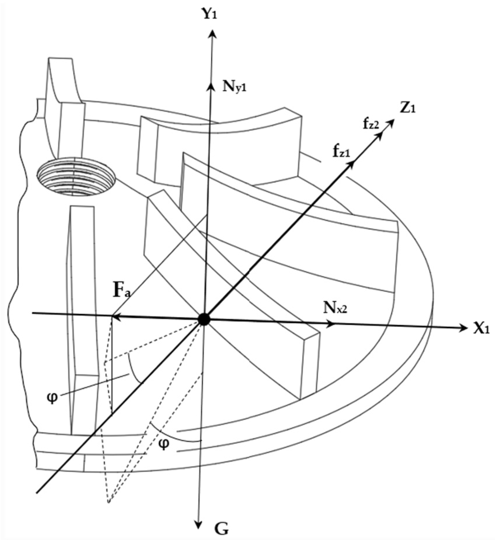
2.2.4. Analysis of the Movement During the Fertilizer Application Process

Take fertilizer particles in a stable state on the centrifugal cone disc that are in contact with the blades and analyze the forces acting on them. The force model is shown in Figure 7. Take the fertilizer particles as the object of analysis and establish a spatial coordinate system X1Y1Z1. The fertilizer particles on the centrifugal cone disc are subject to gravity, support force, friction force, centrifugal force, and other forces.
From Newton’s Second Law, we can obtain
F z 1 = F a cos γ cos φ + G cos φ sin γ f z 1 f z 2
where Fz1 is the resultant external force in the Z1 axis direction, N; Fa is the centrifugal force exerted on the fertilizer particles by the centrifugal cone disc, N; fz1 is the friction force exerted by the centrifugal cone disc on the fertilizer particles, N; fz2 is the friction force exerted by the blades on the fertilizer particles, N.
The kinetic analysis of fertilizer granules on a centrifugal cone disc shows that
F a = m ω v
ω = 2 π n 60
f z 1 = μ a 1 G cos γ cos φ F a sin γ
f z 2 = μ a 2 F a + F a cos γ sin φ G sin γ
where ω is the angular velocity of the centrifugal cone disc, rad/s; v is the linear velocity of the fertilizer particles, m/s; m is the mass of the fertilizer particles, g; μa is the coefficient of friction between the fertilizer particles and the centrifugal cone disc and blades.
From the above analysis, it can be concluded that the motion of fertilizer particles on the centrifugal cone disc is primarily influenced by the rotational speed n of the centrifugal disc, the friction coefficient μa, the cone angle φ of the centrifugal cone disc, and the blade angle γ. In the subsequent EDEM simulation experiments and bench tests, experiments were conducted by varying the rotational speed n, the cone angle φ of the centrifugal cone disc, and the blade angle γ.

2.3. EDEM-Based Simulation Performance Test

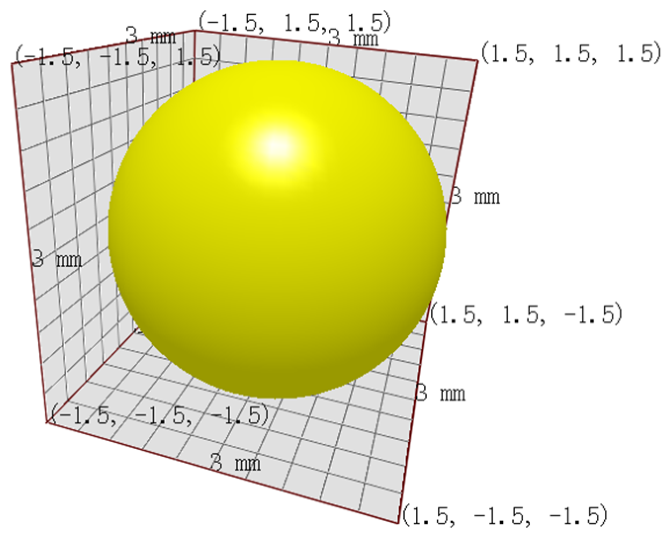
2.3.1. Establishment of Fertilizer Particle Model

Fertilizer particle shape and density will affect the movement characteristics and the amount of fertilizer discharged. EDEM is a high-performance bulk and granular simulation software [24], which can more accurately simulate the actual movement state of fertilizer particles in the process of discharging fertilizers, and also supports the connection and interaction with other software [25]. Taking the potassium sulfate-type compound fertilizer as the research object, this fertilizer particle size is uniform, the sphericity is 96.42%, which is approximate to the sphere, and the particle model is set as spherical particles. According to the national standard GB/T 22923-2008 [26] on the particle size of granular fertilizer (1.0–4.75 mm), and combined with the actual size of potassium sulphate compound fertilizer, the radius of 1.5 mm was selected as the size of fertilizer particles studied in this paper. The fertilizer particle model established in EDEM software is shown in Figure 8.

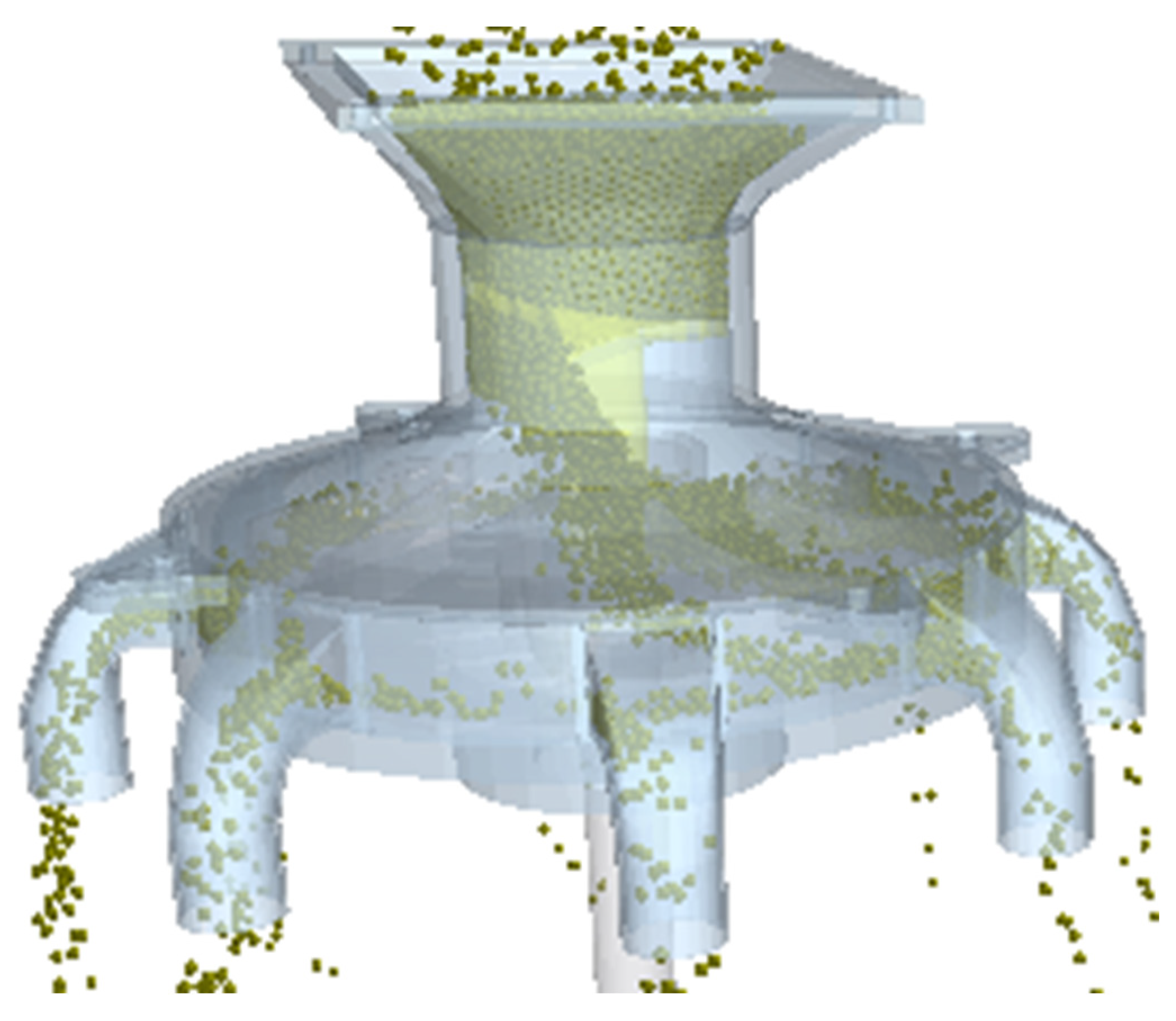
2.3.2. Simulation Model Construction

The design and testing of a multi-row spiral quantitative fertilizer distributor mainly consists of upper shell, spiral quantitative fertilizer feed winches, centrifugal cone discs, fertilizer guide tubes, and fertilizer discharge ports. In EDEM simulation software, the material of each component of the fertilizer distributor is set to high-precision ABS resin, and the 3D model constructed in SolidWorks 2022 is imported into EDEM software in the format of .igs, which provides the basic parameters for the subsequent simulation analysis, and the simulation model of fertilizer distributor in EDEM is shown in Figure 9. The simulation model of fertilizer distributor in EDEM is shown in Figure 9.

2.3.3. Experimental Design

To study the simulation of the design and testing of a multi-row spiral quantitative fertilizer distributor model in EDEM and to conduct a three-factor, three-level test, the fertilizer particles are selected because they are approximately spherical and can be regarded as non-adhesive under normal operating conditions. The Hertz–Mindlin no sliding contact model is used [27]. Referring to the relevant literature, the parameters of the contact between fertilizer particles and between fertilizer particles and fertilizer distributor were determined, and the parameters of its simulation model were set [28], as shown in Table 1.
In order to ensure that the fertilizer particles are stationary in the fertilizer distributor, the centrifugal cone discs start to rotate after 1 s, the rotation time is 12 s, and the mass of fertilizer discharged from the fertilizer guide tubes is taken once every 3 s in this time period. In order to obtain the amount of fertilizer discharged from each fertilizer guide tube, 8 square Grid Bin Groups located parallel to the horizontal plane after each fertilizer guide tube were added in the Setup Selections module of EDEM simulation software, and the mass of fertilizer discharged from each fertilizer guide tube was counted. According to the aforementioned fertilizer distributor structure parameter analysis, we set the fertilizer distributor three factors range: cone disc speed 30~110 r/min, centrifugal cone discs’ cone angle 0°~25.6°, blade inclination angle 0°~6.8°. Test factors and their levels are shown in Table 2.
During the simulation test, in order to ensure the accuracy and reliability of the test data, each group of test conditions was repeated three times, and the errors caused by chance factors were effectively eliminated through multiple tests to make the test results more convincing. Coefficient of variation for the consistency of fertilizer application amount among rows and coefficient of variation for the consistency of fertilizer application amount within the same row were used as evaluation indexes [28]. Coefficient of variation for the consistency of fertilizer application amount among rows and coefficient of variation for the consistency of fertilizer application amount within the same row can be calculated, and their consistency can be obtained from Equations (22) and (23).
Z 1 = i = 1 N Z i j
Y = 1 N 1 Z i Z 1 2 Z 1 × 100 %
where N is the number of fertilizer guide tubes (N = 8); Z1 is the mean value of fertilizer mass discharged from N fertilizer guide tubes, g; Zi is the mass of fertilizer discharged from the ith guide tube, g; at this time, Y is coefficient of variation for the consistency of fertilizer application amount among rows, %. If N is the number of trials (N = 3), Z1 is the average amount of fertilizer discharged from the eight guide tubes under N trials, g; Zi is the mass of fertilizer discharged from the guide tubes under the ith trial, g; at this time, Y is coefficient of variation for the consistency of fertilizer application amount within the same row, %.

2.4. Bench Test

Through the previous analysis, the fertilizer particles can be discharged at the fertilizer distributor centrifugal cone discs’ speed of 30 r/min. In order to adapt to the requirements of different fertilizer application rates, a one-factor test of fertilizer distributor centrifugal cone discs’ speed was carried out. The speed of centrifugal cone discs is 30, 40, 50, 60, 70, 80, 90, 100, 110 r/min, with 9 levels. Potassium sulphate compound fertilizer was selected as the test material for this test, and a homemade fertilizer distributor performance test bench was used to carry out the bench test, in which the fertilizer distributor was 3D-printed and molded by high-precision ABS resin; the fertilizer discharging performance test bench is shown in Figure 10.
When carrying out the fertilizer distributor fertilizer discharge performance test, the test method specified in NY/T 1143-2006 [29] Technical Specification for Quality Evaluation of Seeders was followed [30]. The steps were as follows: the speed of the loaded motor was measured with a SW6234C laser tachometer, and the motor speed was adjusted by a speed controller. For each test, the fertilizer distributor was rotated continuously for 20 s. The fertilizer discharged from the guide tube was collected and weighed using a catch bag. To ensure the accuracy of the test results, each test was repeated three times and the average of the three test results was taken.

3. Test Results

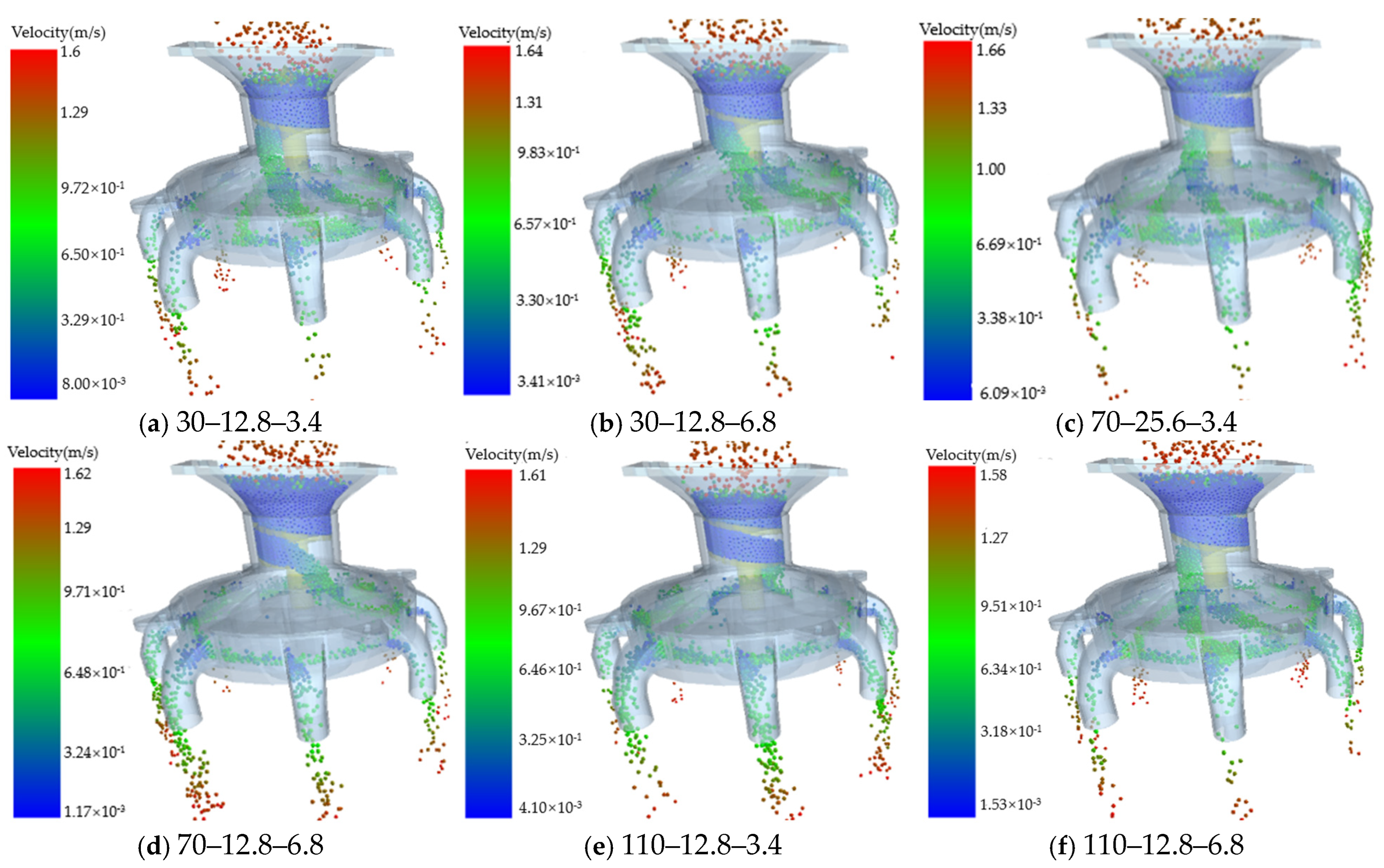
3.1. Simulation Test

The simulation test was carried out by EDEM software; part of the test process is shown in Figure 11, and the results of the test (X1, X2, and X3 are factor-coded values) are shown in Table 3. Quadratic regression analysis was carried out using Design-Expert 13 to obtain the coefficient of variation for the consistency of fertilizer application amount among rows Yv1 and the coefficient of variation for the consistency of fertilizer application amount within the same row Yv2 regression equations and analyze their significance.

3.1.1. Coefficient of Variation for the Consistency of Fertilizer Application Amount Among Rows Yv1 Significance Level Analysis

Through the analysis of variance and significance of the quadratic regression model, the data in Table 4 show that the effects of X1, X12, and X32 are highly significant, X2 and X22 are significant, and the rest of the factors have insignificant effects, which can be eliminated to obtain the coefficient of variation for the consistency of fertilizer application amount among rows quadratic regression model, which is
Y v 1 = 5.98 0.655 X 1 0.4287 X 2 3.07 X 1 2 + 0.693 X 2 2 0.9058 X 3 2
According to Table 4, it can be seen that the fitted model can reflect the relationship between the factors and the error, and can predict the experimental results. Through the magnitude of the p value, it can be judged that the order of the influence of the three factors on the coefficient of variation for the consistency of fertilizer application amount among rows Yv1 is centrifugal cone discs’ rotational speed X1, centrifugal cone discs’ cone angle X2, and blade inclination angle X3.

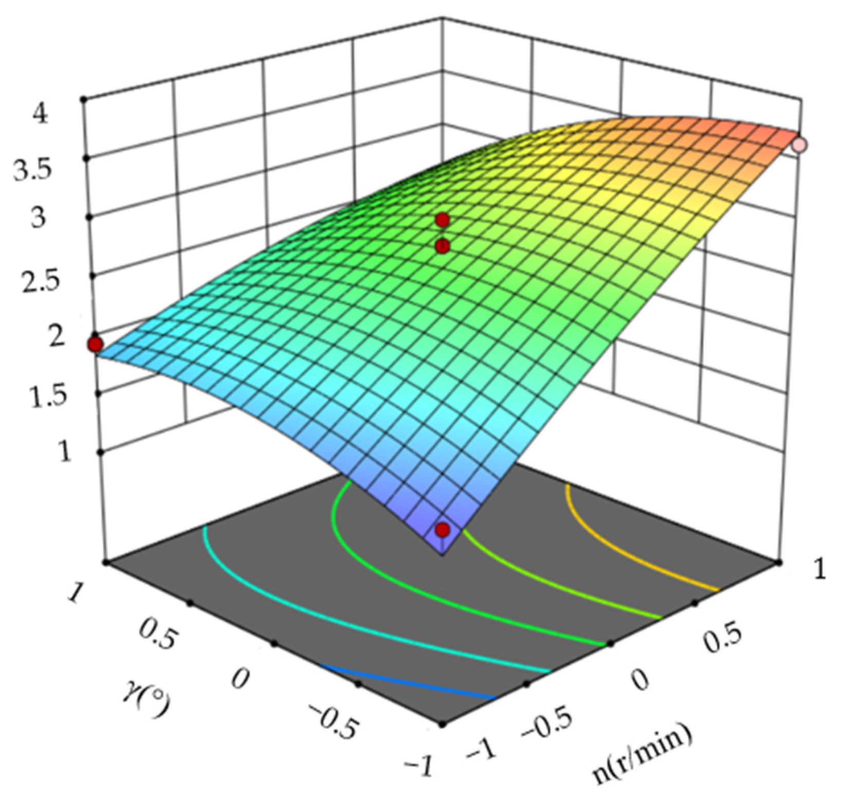
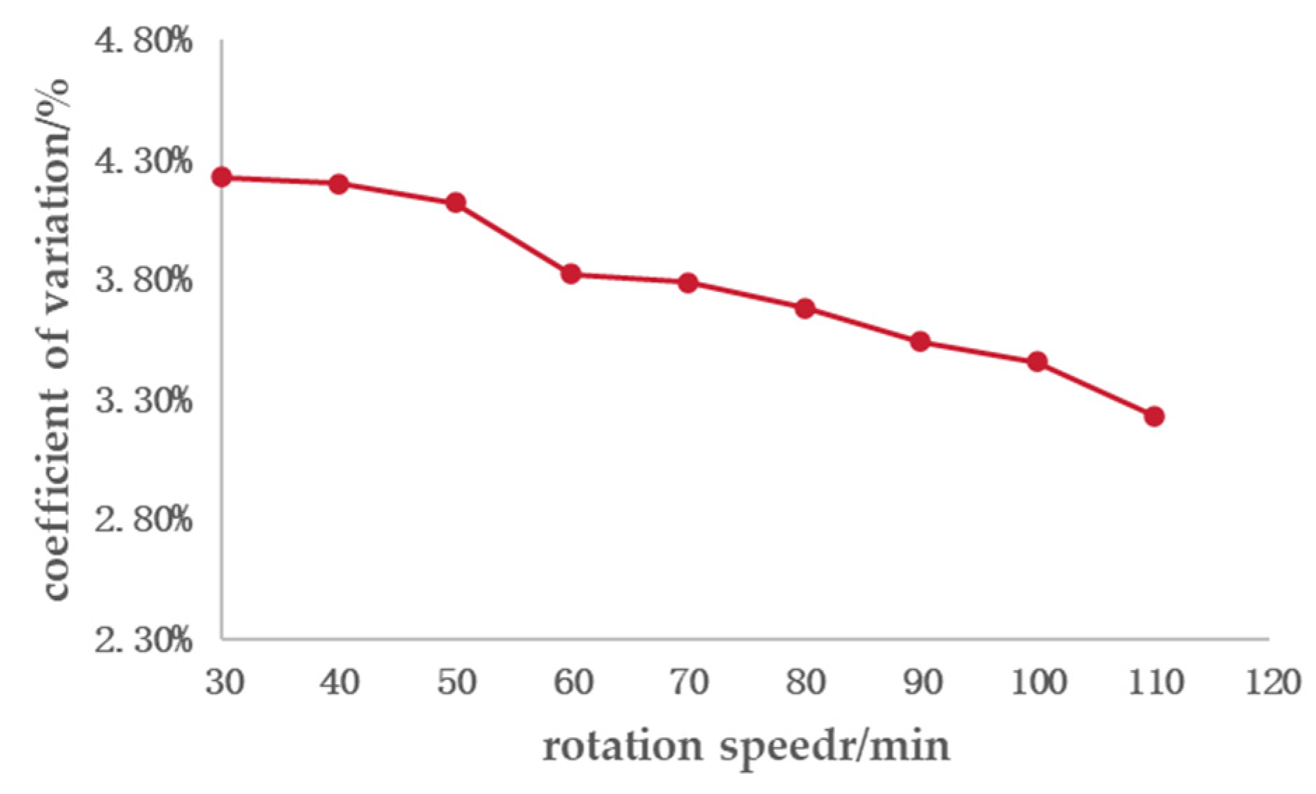
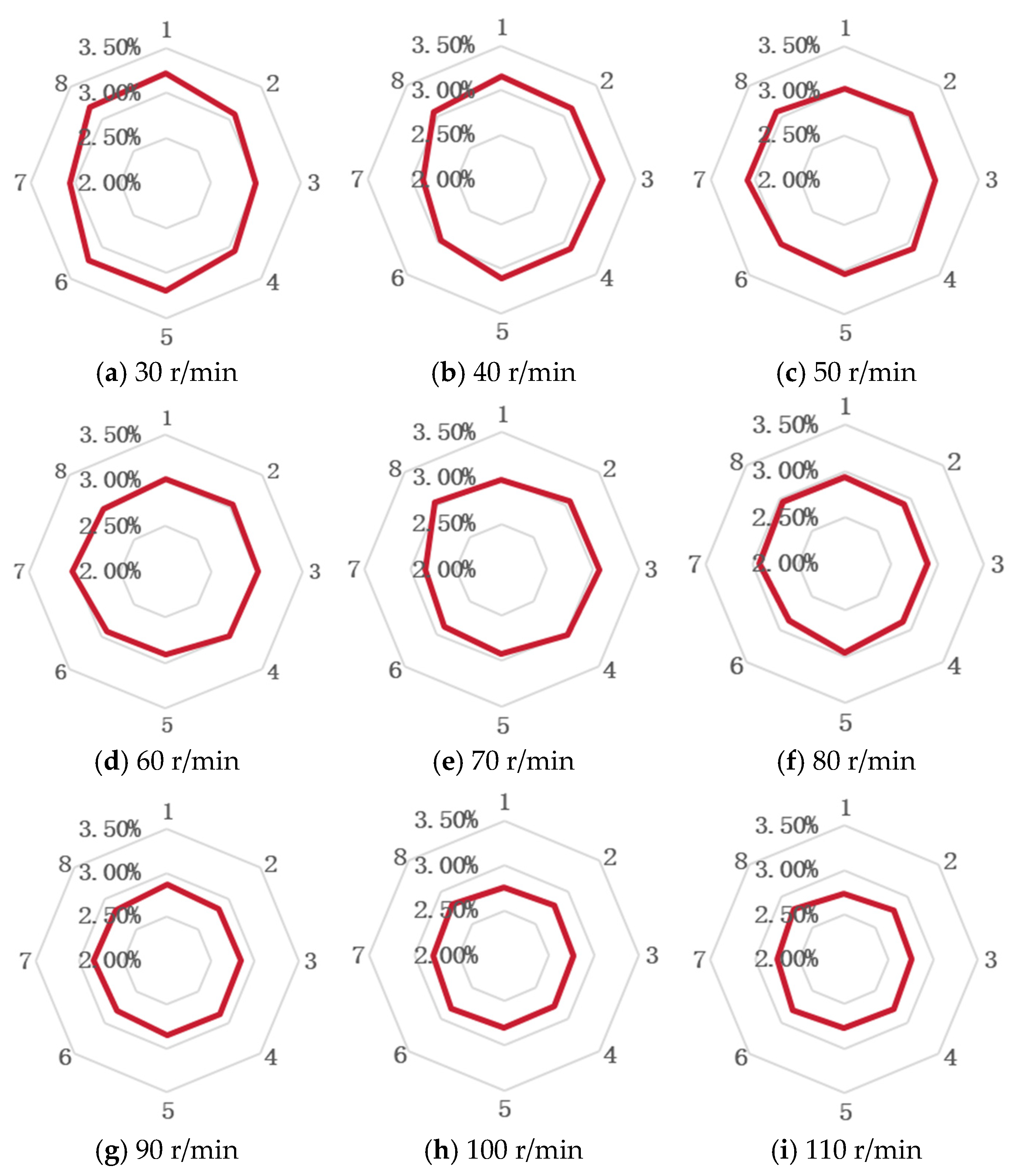
3.1.2. Coefficient of Variation for the Consistency of Fertilizer Application Amount Within the Same Row Yv2 Significance Analysis

Through the variance and significance analysis of the quadratic regression model, the data in Table 5 indicate that the effects of X1, X2, X1X3, X32 are highly significant, and the insignificant items can be excluded to obtain the coefficient of variation for the consistency of fertilizer application amount within the same row quadratic regression equation as
Y v 2 = 2.77 + 0.7925 X 1 0.21 X 2 0.39 X 1 X 3 0.2605 X 3 2
According to Table 5, it can be seen that the fitted model can reflect the relationship between the factors and the error, and can predict the experimental results. Through the magnitude of p-value, it can be judged that the order of influence of the three factors on the variation coefficient of intra-row fertilizing amount consistency Yv2 is centrifugal cone discs’ rotational speed X1, centrifugal cone discs’ cone angle X2, and blade inclination angle X3.
The post-processing of the test data was carried out by using Design-Expert 13 software, which in turn resulted in its response surface map as shown in Figure 12.
As can be seen from Figure 12, the optimal coefficient of variation values and the optimal combinations of parameters can be obtained by using the Optimization-Numerical module of the Design-Expert 13 software. The coefficient of variation for the consistency of fertilizer application amount among rows Yv1 ≤ 4.33%, the coefficient of variation for the consistency of fertilizer application amount within the same row Yv2 ≤ 3.15%, and the optimal parameters of each factor are as follows: the cone disc rotational speed is 94.57 r/min, the cone disc taper angle is 16.71°, and cone disc blade inclination is 2.68°. In order to facilitate the processing and debugging of the equipment, the speed of the centrifugal cone discs was selected to be 95 r/min, the cone disc cone angle to be 16.7°, and the cone disc blade inclination to be 2.7°, without affecting the accuracy of the experimental results.
In order to verify the performance of the fertilizer distributor under the optimal parameter combinations, the experimental variables were set to the optimal parameter values and imported into EDEM for three simulation tests. After analysis of the simulation results, taking the average of the three times data, the coefficient of variation for the consistency of fertilizer application amount among rows Yv1 was 4.14%, and coefficient of variation for the consistency of fertilizer application amount within the same row Yv2 was 3.07%, which was in general consistent with the predicted values. Therefore, when the rotational speed of centrifugal cone discs was 95 r/min, the cone angle of cone discs was 16.7°, and the inclination angle of cone discs’ blades was 2.7°, indicating that the fertilizer distributor had a better fertilizer discharge performance. The fertilizer distributor has a good fertilizer discharge performance.

3.2. Bench Test

In order to further validate the optimized fertilizer distributor’s fertilizer discharge performance and the adaptability of the fertilizer distributor under different rotational speeds, based on the optimal parameter combinations of the fertilizer distributor, the verification test of fertilizer distributor performance and the fertilizer discharge performance test under different rotational speeds were conducted. The coefficient of variation for the consistency of fertilizer application amount among rows of centrifugal cone discs at different rotational speeds is shown in Figure 13.
From the curve of the variation coefficient with cone disc rotational speed in Figure 13, it can be seen that the coefficient of variation for the consistency of fertilizer application amount among rows is lower than 4.25% under the lowest rotational speed of fertilizer, and the coefficient of variation for the consistency of fertilizer application amount among rows decreases with the increase in cone speed, but the decrease is small; the test result meets the requirements of the industry standard, and meets the requirements of the quality of the fertilizer discharge, which indicates that the fertilizer distributor has a better fertilizer discharge performance.
The coefficient of variation for the consistency of fertilizer application amount within the same row is an important index to measure the stability of fertilizer discharge amount, which is the guarantee of the continuous fine amount of fertilizer supply to each fertilizer conduit pipeline [28]. Centrifugal cone discs turn through 1~8 fertilizer discharge ports in turn. The coefficient of variation for the consistency of fertilizer application amount within the same row with the rotational speed of centrifugal cone discs is analyzed in Figure 14. It can be observed that when the rotational speed of the cone discs is increased, the variation coefficient of intra-row fertilizing amount consistency decreases, but the magnitude of the decrease is small, and the variation coefficient of intra-row fertilizing amount consistency of each fertilizer catheter varies less. The consistency of each catheter is small. According to the results of the bench test, it can be seen that the fertilizer distributor has a better stability of fertilizing amount.
Through EDEM simulation analysis and bench test performance verification of the designed fertilizer applicator, the coefficients of variation for within-row and inter-row fertilizer application consistency obtained from EDEM simulation show little difference from those verified by bench tests. This further demonstrates that the fertilizer applicator has good fertilization uniformity and superior fertilization performance. Meanwhile, in constant-speed and variable-speed fertilization performance tests, the errors of inter-row and within-row consistency coefficients of variation both comply with national standards, being lower than 10.23% and 3.52%, respectively [31], indicating the designed fertilizer applicator performs excellently.

4. Discussion

In the selection of experimental materials, potassium sulfate compound fertilizer was chosen as the research object. Its particle size is uniform and the sphericity is as high as 96.42%. The nearly spherical characteristic enables the particle model to be simplified to spherical in the EDEM simulation, which is convenient for simulation analysis. At the same time, it is also consistent with the commonly used fertilizer types in actual agricultural production, ensuring the representativeness of the experimental materials. In terms of method design, the key parameters of the fertilizer discharger were systematically decomposed. From the design of parameters such as the top angle of the arch-breaking cone and the width of the spiral blade of the quantitative fertilizer supply mechanism, to the determination of parameters such as the diameter of the centrifugal fertilizer distribution disc, the inclination angle of the blade, and the inclination angle of the cone disc, both the physical characteristics of fertilizer particles (such as the natural angle of repose 25.6°) and the working principle of the fertilizer discharger were combined. A complete parameter design system has been formed. The dynamic analysis of the fertilizer supply process, by establishing the force model of the fertilizer micro-element, clarified the action mechanism of each force in the screw conveyor device, providing a theoretical basis for parameter optimization. The combination of EDEM simulation and bench tests, from virtual simulation to actual verification, has constructed a comprehensive research method system, ensuring the reliability and scientific nature of the research results.
The simulation experiment adopted a three-factor and three-level design. With the rotational speed of the cone disk, the cone angle of the cone disk, and the blade inclination angle as variables, and the coefficient of variation of the consistency of fertilizer discharge in each row and the same row as the evaluation index, the movement of fertilizer particles was simulated through the Hertz–Mindlin non-sliding contact model, effectively capturing the influence of each parameter on the fertilizer discharge performance. Analysis of variance shows that the rotational speed of the cone disk has an extremely significant influence on the uniformity of fertilizer discharge, followed by the cone angle of the cone disk, and the blade inclination angle has a relatively small influence. This provides a clear direction for parameter optimization. The optimal parameter combination obtained through the Design-Expert 13 software (cone disk rotational speed 95 r/min, cone disk cone angle 16.7°, blade inclination angle 2.7°) was verified by simulation. The coefficient of variation for the consistency of fertilizer application amount among rows was 4.14%, and the coefficient of variation for the consistency of fertilizer application amount within the same row was 3.07%. All meet the requirements of fertilizer discharge quality. Domestic scholars Xu Chunbao et al. designed a centrifugal cavity disc extrusion-type high-speed precise fertilizer applicator for rapeseed, which can also achieve multi-row fertilization with one device. The simulation test results show that the coefficient of variation for the consistency of fertilizer application amount among rows and the coefficient of variation for the consistency of fertilizer application amount within the same row are, respectively, lower than 8.58% and 6.45% [16]. This indicates that the fertilizer applicator designed in this paper has further improved fertilization performance. Meanwhile, it shows that the simulation model can accurately predict the performance of the fertilizer discharge device, providing an efficient virtual test method for structural optimization, avoiding a large number of blind physical tests, and saving time and cost.
The bench test conducted a single-factor test within the rotational speed range of 30–110 r/min. The results showed that the coefficient of variation for the consistency of fertilizer application amount among rows decreased with the increase in rotational speed and was always lower than 4.25%. The coefficient of variation for the consistency of fertilizer application amount within the same row was lower than 3.21%. Meanwhile, both are, respectively, lower than 10.23% and 3.52% [31], verifying the stability of the fertilizer applicator design and the reliability of actual operations. This indicates that the fertilizer discharger has good uniformity and stability in fertilizer discharge at different rotational speeds. In the test, the fertilizer discharge device was formed by 3D printing with high-precision ABS resin, ensuring consistency between the structural accuracy and the actual working conditions. The test method followed the NY/T 1143-2006 standard. Through multiple repeated tests and taking the average value, the random error was effectively reduced. The bench test results are highly consistent with the simulation results, further confirming the design rationality of a multi-row spiral quantitative fertilizer discharge device. This provides a solid experimental basis for its practical application in precise fertilization in agricultural production and also reflects the important value of the research method combining simulation and experimentation in the design of agricultural machinery.

5. Conclusions

Through the establishment and analysis of the motion model of fertilizer particles in the fertilizer distributor, the parameter ranges such as the cone angle of the centrifugal cone disk, the inclination angle of the cone disk, and the rotational speed of the cone disk were determined. Using the EDEM discrete element simulation software, a three-factor and three-level experiment influencing the fertilizer discharge performance of the fertilizer distributor was carried out, and the Design-Expert 13 software was used to determine that the optimal structural parameters of the fertilizer distributor were as follows: the rotational speed of the centrifugal cone disk was 95 r/min, the cone angle of the cone disk was 16.7°, and the blade inclination angle was 2.7°. In order to verify the performance of the fertilizer distributor’s fertilizer discharge, a bench test was carried out. The bench test of the fertilizer distributor showed that the coefficient of variation for the consistency of fertilizer application amount among rows Yv1 was lower than 4.25%, and the coefficient of variation for the consistency of fertilizer application amount within the same row Yv2 was lower than 3.21%, which can meet the requirements of national standards. Next, we will conduct further field trials to verify the field performance of the fertilizer spreader, clarify its operational performance in the field, and provide a theoretical basis for further optimization and improvement.

Author Contributions

Conceptualization, F.M.; methodology, J.H.; software, M.C.; validation, J.H.; formal analysis, J.H.; data curation, J.H.; writing—original draft preparation, J.H.; writing—review and editing, X.L.; visualization, E.W.; supervision, L.Y.; project administration, H.D. and H.Z. All authors have read and agreed to the published version of the manuscript.

Funding

This research was funded by the following fund projects: Doctoral Scientific Research Foundation of Pingdingshan University (PXY-BSQD-2023023). Project of the Science and Technology Department of Henan Province under Grant 242102111172, Grant 242102111173, Grant 242102220079 and Grant 252102220130.

Data Availability Statement

The original contributions presented in this study are included in the article. Further inquiries can be directed to the corresponding author.

Conflicts of Interest

Enchao Wan was employed by the Jinan Heavy Industry Engineering Co., Ltd. The remaining author declares that the research was conducted in the absence of any commercial or financial relationships that could be construed as a potential conflict of interest.

References

  1. Tang, H.; Wang, J.; Xu, C.; Zhou, W.; Wang, J.; Wang, X. Research progress analysis on key technology of chemical fertilizer reduction and efficiency increase. Trans. Chin. Soc. Agric. Mach. 2019, 4, 1–19. [Google Scholar]
  2. Song, L.; Zhang, R. Research on change trend and risk of China’s food production. J. Agric. Sci. Technol. China 2023, 2, 1–9. [Google Scholar]
  3. Chen, Y.; Sun, Y. Study on the production increasing potential and guarantee capacity of grain in China in the next 30 years. J. Sichuan Agric. Univ. 2022, 33, 312–318. [Google Scholar]
  4. Yang, S.; Yan, X. Research on the risk assessment of farmland non-point source pollution at regional scale from the perspective of crop fertilizer application amount. J. China Agric. Univ. 2023, 22, 147–159. [Google Scholar]
  5. Gao, L.; Zhang, Q.; Chen, H.; Wang, H.; Liu, W.; Zhang, S.; Xu, G.; Shen, Y. Pollution status and control measures of agricultural non-point source pollution in China. Phosphate Compd. Fertil. 2018, 88, 37–38, 45. [Google Scholar]
  6. Feng, S. Research on the impact of agricultural mechanization on agricultural development. South Agric. Mach. 2025, 8, 171–173+180. [Google Scholar]
  7. Ou, M.; Wang, G.; Lu, Y.; Zhang, Z.; Pan, H.; Jia, W.; Dong, X. Structure Optimization and Performance Simulation of a Double-Disc Fertilizer Spreader Based on EDEM-CFD. Agronomy 2025, 5, 1025. [Google Scholar] [CrossRef]
  8. Gao, Y.; Feng, K.; Yang, S.; Han, X.; Wei, X.; Zhu, Q.; Chen, L. Design and Experiment of an Unmanned Variable-Rate Fertilization Control System with Self-Calibration of Fertilizer Discharging Shaft Speed. Agronomy 2024, 10, 2336. [Google Scholar] [CrossRef]
  9. Guo, Q.; Quan, B.; Sun, H.; Ji, X.; Yu, Z.; Wang, H.; Wu, X.; Wei, Y.; Zhang, C.; Shang, G.; et al. Design Optimization and Experimentation of Triple-Head Gradually Reducing Spiral Precision Fertilizer Apparatus. Processes 2024, 9, 1988. [Google Scholar]
  10. Peng, M.; Zhang, Z.; Zhang, W.; Huang, H.; Zhang, G.; Liu, W.; Wu, X.; Zhang, J. Design and Optimization of Sugarcane Spiral Fertilizer Applicator Based on Response Surface Methodology and Artificial Neural Networks. Processes 2023, 10, 2881. [Google Scholar] [CrossRef]
  11. Li, H. Design and Test of the Screw Auger Fertilizer—Discharging Device for Oil—Tea Camellia Forests. Master’s Thesis, Jiangxi Agricultural University, Nanchang, China, 2024. [Google Scholar]
  12. Dun, G.; Liu, W.; Wu, X.; Mao, N.; Ji, W.; Ma, H. Simulation optimization and experiment of screw extrusion precision fertilizer ejector. J. Jilin Univ. (Eng. Technol. Ed.) 2023, 10, 3026–3037. [Google Scholar]
  13. Sui, X. Development of a Tou-Row Equal Application Vehicle for Granular Organic Fertilizers in Blueberry Plantations and Study of Consistency of Application and Sowing. Master’s Thesis, Qingdao University of Technology, Qingdao, China, 2024. [Google Scholar]
  14. Xu, W.; Yuan, Q.; Zeng, J.; Lü, X. Design and Experiment of Four-head Inclined Spiral Precision Fertilizer Dischargers in Orchard. Trans. Chin. Soc. Agric. Mach. 2024, Z2, 30–40. [Google Scholar]
  15. Zhang, X.; Wu, Y.; Li, J.; Wang, L.; Tong, Z.; Chen, X. Design and experiment of tobacco pellet fertilizer mixture applicator. J. Henan Agric. Univ. 2020, 5, 829–835. [Google Scholar]
  16. Xu, C.; Dong, W.; Li, H.; Yu, Q.; Zhang, C.; Ding, Y. Design and experiment of a centrifugal cavity disc extrusion type high-speed precision fertilizer apparatus for rapeseed. Trans. Chin. Soc. Agric. Eng. 2024, 20, 22–34. [Google Scholar]
  17. Shi, J. Optimized Design of Fertilizer Distributor for Substrate-Covered No-Till Planter and Its Impact on Maize Growth. Master’s Thesis, Heilongjiang Bayi Agricultural University, Daqing, China, 2024. [Google Scholar]
  18. Shi, Y.; Chen, M.; Wang, X.; Morice, O.O.; Ding, W. Numerical simulation of spreading performance and distribution pattern of centrifugal variable-rate fertilizer applicator based on DEM software. Comput. Electron. Agric. 2018, 144, 249–259. [Google Scholar]
  19. Song, S. Optimal Design and Experimental Research on the Layered Fertilizer Apparatus of the Specific row-Following Layered Fertilize. Master’s Thesis, Shihezi University, Xinjiang, China, 2021. [Google Scholar]
  20. Wang, X.; Shi, J.; Li, X.; Jiang, Q.; Zhan, C.; Song, Z. Analysis of Research Status and Development Trends of Organic Fertilizer Applicators at Home and Abroad. Agric. Dev. Equip. 2025, 4, 100–103. [Google Scholar]
  21. Xue, Z.; Zhao, L.; Wang, F.; Wang, S.; Song, G.; Wang, G. Study on the Performance of Spiral Fertilizer Distributor Based on EDEM. J. Agric. Mech. Res. 2020, 6, 87–95. [Google Scholar]
  22. Zhu, Q. Study on Inclined Fluted Roller Fertilizer Distributor. Master’s Thesis, College of Engineering, South China Agricultural University, Guangzhou, China, 2017. [Google Scholar]
  23. China Academy of Agricultural Machinery Sciences (CAAMS). Agricultural Machinery Design Handbook; China Academy of Agricultural Machinery Sciences (CAAMS): Beijing, China, 2007. [Google Scholar]
  24. Wang, Y. Research on Key Parameters and Fertilization Performance of Outer Groove-Wheel Fertilizer Apparatus Based on EDEM. Master’s Thesis, Tarim University, Xinjiang, China, 2024. [Google Scholar]
  25. Qi, J.; Deng, Y.; Zhang, J.; Meng, H.; Li, Y. Design and Experiment of Manure and Granular Fertilizer Mixed Fertilizer Discharging Device Based on EDEM. J. Chin. Agric. Mech. 2025, 4, 1–9. [Google Scholar]
  26. GB/T 22923-2008; Determination of Nitrogen Phosphorus Potassium for Fertilizers by Auto Analyzer. Standardization Administration of the People’s Republic of China: Beijng, China, 2008.
  27. Liu, X.; Hu, R.; Wang, D.; Lu, B.; Wang, W.; Ding, Y. Optimization and Experiment of Fertilizer Discharger Based on Granular Fertilizer Motion Model. Trans. Chin. Soc. Agric. Mach. 2021, 12, 85–95. [Google Scholar]
  28. Liu, X. Design and Experiment on Precise Discharge-Apply Fertilizer System of Rapeseed Planter. Ph.D. Thesis, Huazhong Agricultural University, Wuhan, China, 2022. [Google Scholar]
  29. NY/T 1143-2006; Technical Specifications of Quality Evaluation for Drills. Ministry of Agriculture of the People’s Republic of China: Beijng, China, 2006.
  30. Liao, Q.; Shen, W.; Wang, L.; Huo, J.; Luo, Z.; Liao, Y. Design and Experiment of High-speed Mechanical Centrifugal Collecting and Discharging Device for Rapeseed. Trans. Chin. Soc. Agric. Mach. 2024, 7, 154–167. [Google Scholar]
  31. Liu, X.; Lü, Q.; Li, G.; Wang, J.; Yan, D.; Yang, L.; Liu, E. Design Optimization and Experimental Verification of Spiral Cone Centrifugal Fertilizer Apparatus Based on the Discrete Element Method. Processes 2023, 11, 199. [Google Scholar] [CrossRef]
Figure 1. Schematic sketch of the fertilizer discharge unit: 1—upper housing; 2—screw winch unit; 3—fertilizer guide tube; 4—lower housing; 5—turntable shaft; 6—centrifugal cone discs.
Processes 13 01992 g001
Figure 2. Partial section of the spiral device.
Processes 13 01992 g002
Figure 3. Top view of centrifugal cone disc.
Processes 13 01992 g003
Figure 4. Local blade angle analysis diagram.
Processes 13 01992 g004
Figure 5. Partial section of centrifugal cone disc.
Processes 13 01992 g005
Figure 6. Force analysis of fertilizer particles on spiral blades.
Processes 13 01992 g006
Figure 7. Force analysis of fertilizer granules on a centrifugal cone disc.
Processes 13 01992 g007
Figure 8. Fertilizer particle model.
Processes 13 01992 g008
Figure 9. Fertilizer distributor simulation model.
Processes 13 01992 g009
Figure 10. Fertilizer distributor performance test stand: 1—Fertilizer box; 2—Fertilizer distributor; 3—Fertilizer bag; 4—DC gear motor; 5—Speed controller.
Processes 13 01992 g010
Figure 11. Simulation process of fertilizer distributor under different combinations of factors.
Processes 13 01992 g011
Figure 12. Response surface.
Processes 13 01992 g012
Figure 13. Variation curve of coefficient of variation with cone disc speed.
Processes 13 01992 g013
Figure 14. Coefficient of variation for the consistency of fertilizer application amount within the same row in relation to rotational speed of centrifugal cone discs.
Processes 13 01992 g014
Table 1. Simulation parameter settings.
ItemParameterValue
Fertilizer granulesPoisson’s ratio0.25
Shear modulus/pa1.1 × 108
Density/kg·m−3845.61
Fertilizer distributorPoisson’s ratio0.394
Shear modulus/pa8.9 × 108
Density/kg·m−31060
Fertilizer granules–Fertilizer granulesCoefficient of recovery0.3
Coefficient of static friction0.34
Coefficient of rolling friction0.16
Fertilizer granules–Fertilizer distributorCoefficient of recovery0.2
Coefficient of static friction0.18
Coefficient of rolling friction0.01
Table 2. Test factors and their levels.
LevelFactor
Cone Disc Speed N (r/min)Cone Disc Cone Angle φ (°)Cone Disc Blade Inclination Angle γ (°)
−13000
07012.83.4
111025.66.8
Table 3. Test results.
Experimentation
Control
FactorCoefficient of Variation for the Consistency of Fertilizer Application Amount Among Rows Yv1 (%)Coefficient of Variation for the Consistency of Fertilizer Application Amount Within the Same Row Yv2 (%)
Cone Disc Speed X1 Cone Disc Cone Angle X2 Cone Disc Blade Inclination Angle X3
10−116.242.41
20115.461.96
30006.522.57
41−102.653.81
5−10−12.321.57
60−1−15.652.56
701−15.242.19
81012.022.45
91102.562.95
100005.573.01
1110−11.123.63
12−1−105.431.49
130006.492.79
14−1012.561.95
150005.372.79
160005.972.67
17−1103.281.49
Table 4. Yv1 regression ANOVA.
SourceSum of SquaresdfMean SquareF-Value p-ValueSignificance
Model51.6795.7424.650.0002**
X13.4313.4314.730.0064**
X21.4711.476.310.0402*
X30.475310.47532.040.1962
X1X21.0611.064.550.0702
X1X30.108910.10890.46750.5161
X2X30.034210.03420.14650.7129
X1239.77139.77170.73<0.0001**
X221.3611.365.860.0461*
X323.4573.4514.830.0063**
Residual1.6370.2329
Lack of Fit0.538630.17950.65770.6194
Pure Error1.0940.2730
Cor Total53.3116
Note: ** is highly significant (p < 0.01); * is significant (0.01 < p < 0.05).
Table 5. Yv2 regression ANOVA.
SourceSum of SquaresdfMean SquareF-Valuep-ValueSignificance
Model6.9590.772017.070.0006**
X15.0215.02111.08<0.0001**
X20.352810.35287.800.0268**
X30.174110.17413.850.0906
X1X20.184910.18494.090.0829
X1X30.608410.608413.450.0080**
X2X30.001610.00160.035540.8562
X120.046910.04691.040.3426
X220.214110.21414.730.0661
X320.285770.28576.320.0402**
Residual0.316670.0452
Lack of Fit0.208330.06942.56
Pure Error0.108340.0271
Cor Total7.2616
Note: ** is highly significant (p < 0.01).
Disclaimer/Publisher’s Note: The statements, opinions and data contained in all publications are solely those of the individual author(s) and contributor(s) and not of MDPI and/or the editor(s). MDPI and/or the editor(s) disclaim responsibility for any injury to people or property resulting from any ideas, methods, instructions or products referred to in the content.

