Article

Study on the Corrosion Behavior of Graphite Materials in Molten CuSn Alloy

by
Zhifei Cao
1,
Zongbiao Ye
1,*,
Xiangyang Luo
1,
Hongrui Tian
1,
Hengxin Guo
1,
Jianjun Wei
2 and
Fujun Gou
1,*
1
Key Laboratory of Radiation Physics and Technology of the Ministry of Education, Institute of Nuclear Science and Technology, Sichuan University, Chengdu 610064, China
2
Institute of Atomic and Molecular Physics, Sichuan University, Chengdu 610064, China
*
Authors to whom correspondence should be addressed.
Processes 2025, 13(2), 381; https://doi.org/10.3390/pr13020381
Submission received: 3 January 2025 / Revised: 22 January 2025 / Accepted: 27 January 2025 / Published: 30 January 2025
(This article belongs to the Section Materials Processes)

Abstract

:
Graphite, a critical material for furnace walls, is pivotal to the reliability of the carbon-free hydrogen production industry through methane pyrolysis catalyzed by molten metals. This study systematically investigates the corrosion behavior of molten CuSn alloy on three typical commercial graphite materials—low-density graphite (LDG), high-density graphite (HDG), and pyrolytic graphite (PyG)—with a focus on their corrosion resistance and the underlying mechanisms responsible for graphite corrosion over a period of up to 1000 h at 1100 °C. The experimental results show that LDG suffered the most severe corrosion, with a mass loss of up to 60.09% and a hardness decrease from 0.73 GPa to 0.17 GPa, whereas PyG demonstrated the best corrosion resistance, with only a 5.64% mass loss and a hardness drop from 0.52 GPa to 0.35 GPa. SEM and XRD analyses revealed that the porous structures of LDG and HDG suffered significant macroscopic corrosion, caused by the stress from molten metal infiltration and aggregation in the pores, leading to structural collapse. Interestingly, all three types of graphite, including the non-porous PyG, exhibited disordered microstructural degradation as detected by Raman spectroscopy. Molecular dynamics (MD) simulations confirmed that the thermal motion of Cu and Sn atoms primarily drives the microstructural corrosion of graphite, suggesting that the corrosion process involves both micro- and macro-level damage. These findings provide crucial insight into the compatibility of different graphite materials with molten CuSn alloy and valuable guidance for material selection in methane pyrolysis devices.

1. Introduction

Molten metal-catalyzed methane pyrolysis has attracted significant attention as an efficient method for hydrogen production without generating carbon dioxide. [1,2,3]. Catalysts typically operate above 900 °C to enhance hydrogen production rates [4,5,6,7]. At such high temperatures, the corrosion of materials by molten metal catalysts is inevitable [8,9], which hinders the industrial application of methane pyrolysis for hydrogen production [10,11]. Therefore, investigating the corrosion compatibility between furnace wall materials and molten metals in operational environments is crucial for identifying materials that can withstand long-term industrial catalyst corrosion and improving their corrosion resistance.
Stainless steel, ceramics, and graphite are widely used as high-temperature corrosion-resistant materials in various industrial applications [12,13]. Graphite is considered one of the most promising candidates for fabricating molten medium coolant channels in Generation IV nuclear reactors, attributed to its excellent mechanical strength, thermal conductivity, chemical stability at high temperatures, and ease of forming into various shapes [14,15]. In recent years, numerous research has focused on the permeability and corrosion behavior of graphite in molten metals and salts [16,17,18]. For instance, Zhao He et al. [19] explored the infiltration and chemical compatibility of graphite in molten lead-bismuth eutectic at 800 °C, demonstrating its outstanding chemical stability. Similarly, Jagadeesh Sure et al. [20] assessed the corrosion resistance of various carbon materials in molten LiCl–KCl salt at 600 °C, establishing a comprehensive ranking of their corrosion resistance. David Scheiblehner et al. [21,22] had already used graphite as the wall material to carry molten metal for methane pyrolysis. Carbon materials rarely undergo dissolution corrosion in typical molten metals [23,24,25]. Due to the manufacturing method and process of graphite, as a furnace wall material, graphite may be subjected to erosion by high-temperature molten metals, leading to the risk of structural corrosion. To the best of our knowledge, little attention has been given to studying the corrosion compatibility between graphite and molten alloy catalysts used in methane pyrolysis. For example, the molten CuSn alloy catalyst, known for its high catalytic activity and excellent stability, is considered a promising candidate for industrial applications [26,27]. At service temperatures above 1000 °C, graphite corrosion poses significant risks to devices using molten alloys for hydrogen production. This issue must be studied promptly, particularly given the current rapid iterative development of carbon-free hydrogen production technologies.
In this paper, systematic corrosion experiments were carried out using a typical molten CuSn alloy catalyst and various commercial graphite products, including low-density graphite (LDG), high-density graphite (HDG), and pyrolytic graphite (PyG). The study was conducted statically in a high-purity argon atmosphere at 1100 °C for 1000 h. A comprehensive series of material characterization methods were employed to assess the corrosion characteristics of graphite materials in molten CuSn alloys. The main aim of this study was to investigate the corrosion behavior and influencing factors of common commercial graphite materials in molten CuSn alloy under methane pyrolysis hydrogen production conditions. This study provides compatibility data to support the use of graphite materials as a component in methane pyrolysis devices, further advancing the industrialization of hydrogen production via molten metal catalysis in methane pyrolysis.

2. Experimental Procedure

2.1. Materials

The performance indicators of the LDG, HDG, and PyG used in this study are presented in Table 1. The three graphite samples were cut into sheets, with LDG and HDG having a 2 ± 0.1 mm thickness and PyG being 1 ± 0.05 mm thick. The CuSn alloy used in the experiment had a molar ratio of 1:1 and a melting point of approximately 620 °C from the phase diagram. The alloy was prepared by heating and melting 99.999% pure copper granules and 99.999% pure tin blocks in a ZHGP-30 integrated smelting furnace. After thorough mixing, the metal melt was poured into a mold to cool, forming the required experimental block. The oxide layer on the surface was removed using a grinding wheel. The block was ultrasonically cleaned in distilled water for 10 min and then placed in a drying oven for further use. Figure 1 shows the X-ray diffraction pattern of the CuSn alloy at room temperature. The diffraction results indicate that the alloy consists of metallic Sn and the intermetallic compound Cu6.26Sn5, with no other impurities present.

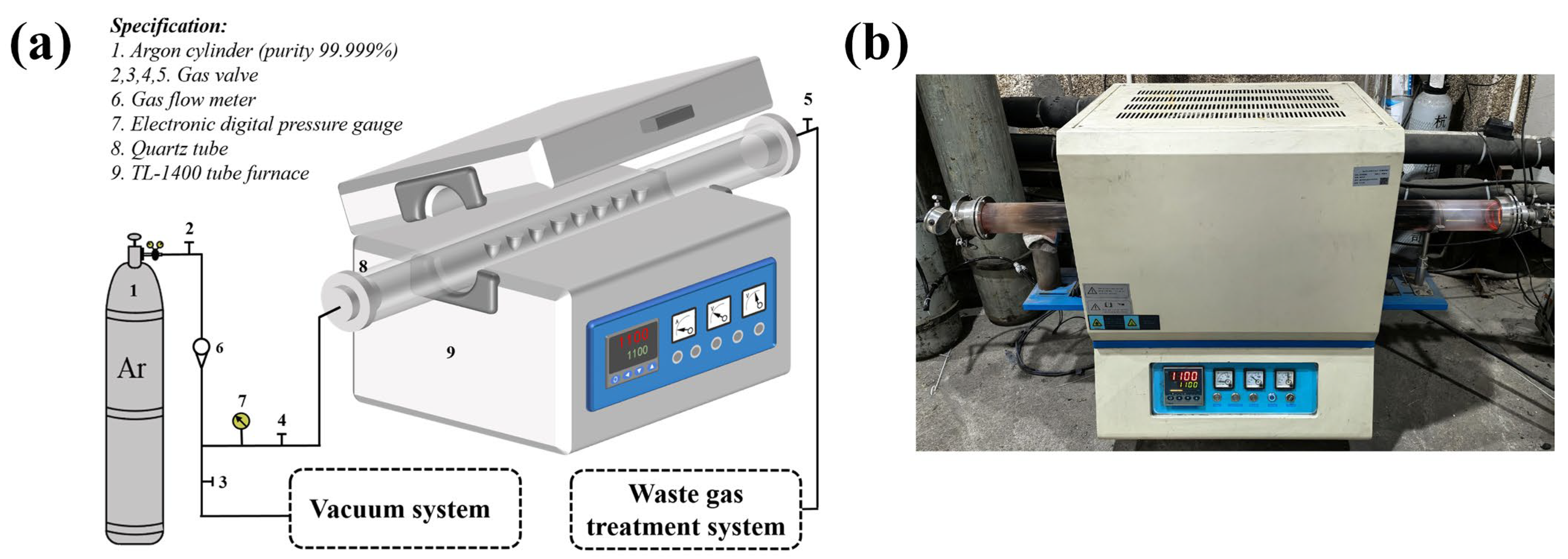
2.2. Static Corrosion Test

The graphite corrosion test was conducted in a tube furnace, as depicted in Figure 2. As the temperature for catalytic methane decomposition with molten CuSn alloy typically ranges from 800 °C to 1100 °C, the compatibility test was performed under the extreme condition of 1100 °C. Prior to the test, the three graphite samples were ultrasonically cleaned in deionized water for 10 min, dried, and weighed. The samples were then placed with 30 g of CuSn alloy blocks in a truncated cone-shaped corundum crucible and inserted into the tube furnace for testing. Before heating, the gas in the tube was replaced three times with ultra-high purity Ar, and the chamber was evacuated to below 10−3 Pa. Ultra-high purity Ar was then refilled to 30 kPa above standard atmospheric pressure. This step aimed to maintain an oxygen-free environment in the container and simulate the pressure conditions for methane pyrolysis. This experiment aimed to investigate the compatibility of graphite materials in molten CuSn alloy; therefore, the effect of reactive gasses such as methane was not considered. Additionally, to study the effect of exposure time on the corrosion of graphite, six samples of each type were prepared for tests lasting from 0 to 1000 h. Samples were collected every 200 h for testing. After each sampling, a perforated crucible was used as a funnel, and the samples were heated to 750 °C under experimental conditions to melt the metal, allowing it to drip off and separate from the graphite. Finally, the graphite samples were ultrasonically cleaned in deionized water for 10 min and dried under argon for subsequent characterization.

2.3. Characterization Methods

The pre- and post-corrosion test weights of the samples were measured using an electronic balance with an accuracy of 0.1 mg. High-resolution scanning electron microscopy (SEM, FEI Inspect F50, Thermo Fisher Scientific, Waltham, Massachusetts, USA) with energy-dispersive spectroscopy (EDS, EDAX, Mahwah, New Jersey, USA) was used to evaluate the distribution of CuSn alloy on the surfaces and cross-sections of the graphite samples and to observe morphological changes. A three-dimensional optical profilometer (Superview WT, Chotest, Shenzhen, China) was used to examine the surface roughness of the graphite samples. Scratched hardness tests on the graphite samples were conducted using an automated scratch tester (WS-2005, Zhongke Kaihua, Lanzhou, China) in a constant-load sliding mode with a load of 20 ± 0.3 N to assess changes in mechanical properties. X-ray diffraction (XRD, Bruker D8 Advance, Bruker Corporation, Billerica, Massachusetts, USA) was used to analyze phase composition and crystal structural transformations in the graphite samples. All diffraction data were collected within the 2θ range of 10° to 90°, with a scanning rate of 5°/min. Raman spectroscopy (DXR2xi Raman Imaging Microscope, Thermo Fisher Scientific, Waltham, Massachusetts, USA, equipped with a 532 nm laser) provided spectra of the graphite materials, indicating changes in structural defects and crystalline order. Finally, molecular dynamics simulations using LAMMPS (Sandia National Laboratories, Albuquerque, New Mexico, USA) were conducted to investigate atomic movements underlying structural transformations.

3. Results and Discussion
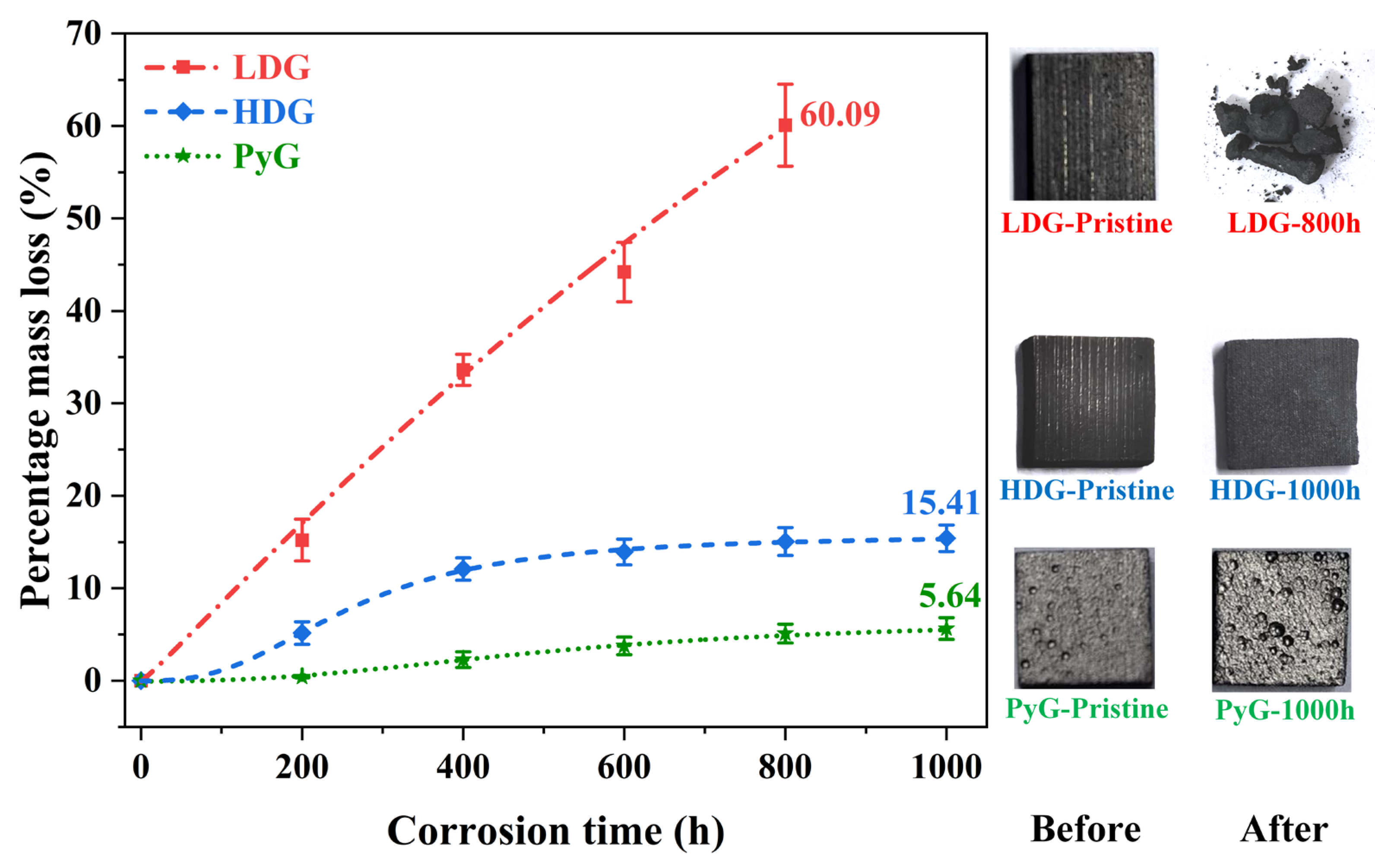
3.1. Mass Loss

After 1000 h of exposure to molten CuSn alloy, the three graphite samples displayed distinct corrosion characteristics. The LDG sample showed significant corrosion, with edges losing sharpness, loose carbon particles on the surface, and a marked reduction in thickness. The number of carbon particles gradually increased over time. After 600 h, a significant number of carbon particles were dislodged from the surface layer, forming distinct pits on the sample surface. After 800 h, the LDG samples disintegrated into powder and were removed from the experiment. Carbon particles in the HDG samples were observed only after 600 h. After 1000 h, no large pores formed, and the thickness remained almost unchanged. The PyG sample remained in its original state after the experiment, showing no visible signs of corrosion and demonstrating better resistance. After each experiment, the samples were weighed, and the percentage change in mass was calculated using the equation:
Δ m = ( m 0 m x ) / m 0
where m0 and mx represent the mass of the graphite sample before corrosion and after x hours of corrosion, respectively. The results are shown in Figure 3, where each data point represents the average weight of multiple measurements at the corresponding contact time for all samples. Two phenomena contribute to the measured mass change: (1) an increase in mass from molten metal infiltration into the pores and retention within the graphite, and (2) a decrease in mass due to the detachment of carbon particles from corrosion. The results show that the percentage mass loss for LDG (powder after 800 h) and HDG (after 1000 h) reached 60.09% and 15.41%, respectively, while PyG (after 1000 h) had only 5.64%, corresponding to the observed shedding of carbon particles from the graphite surface.

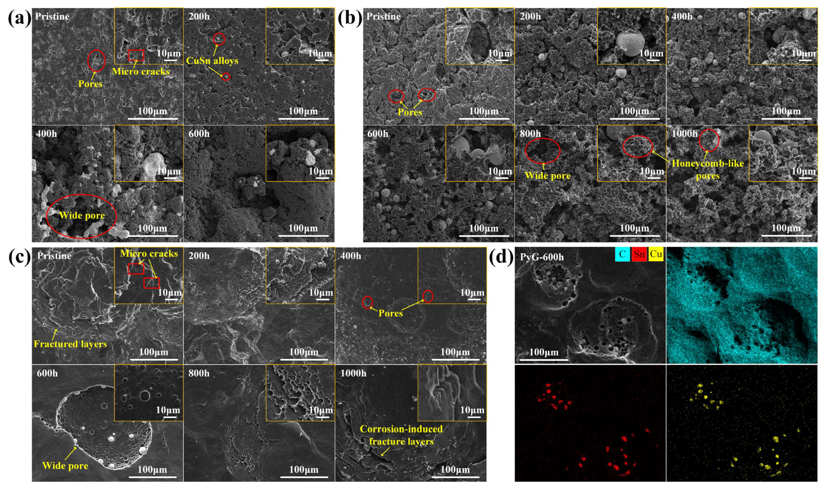
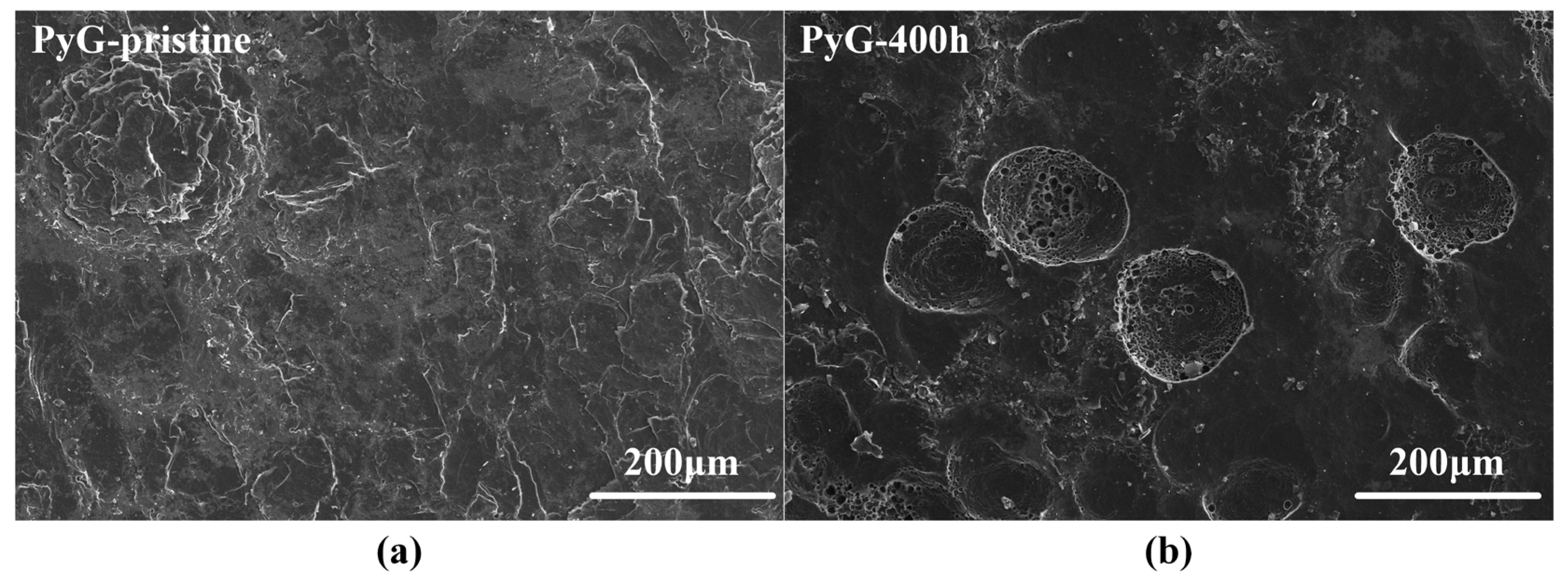
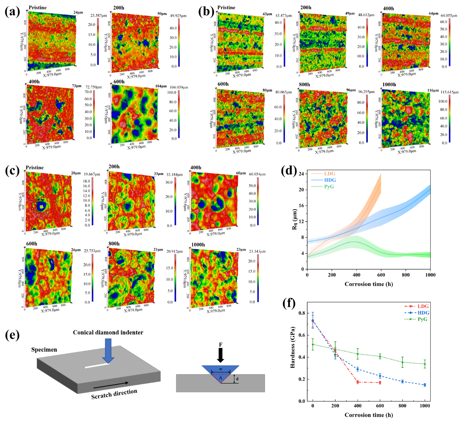
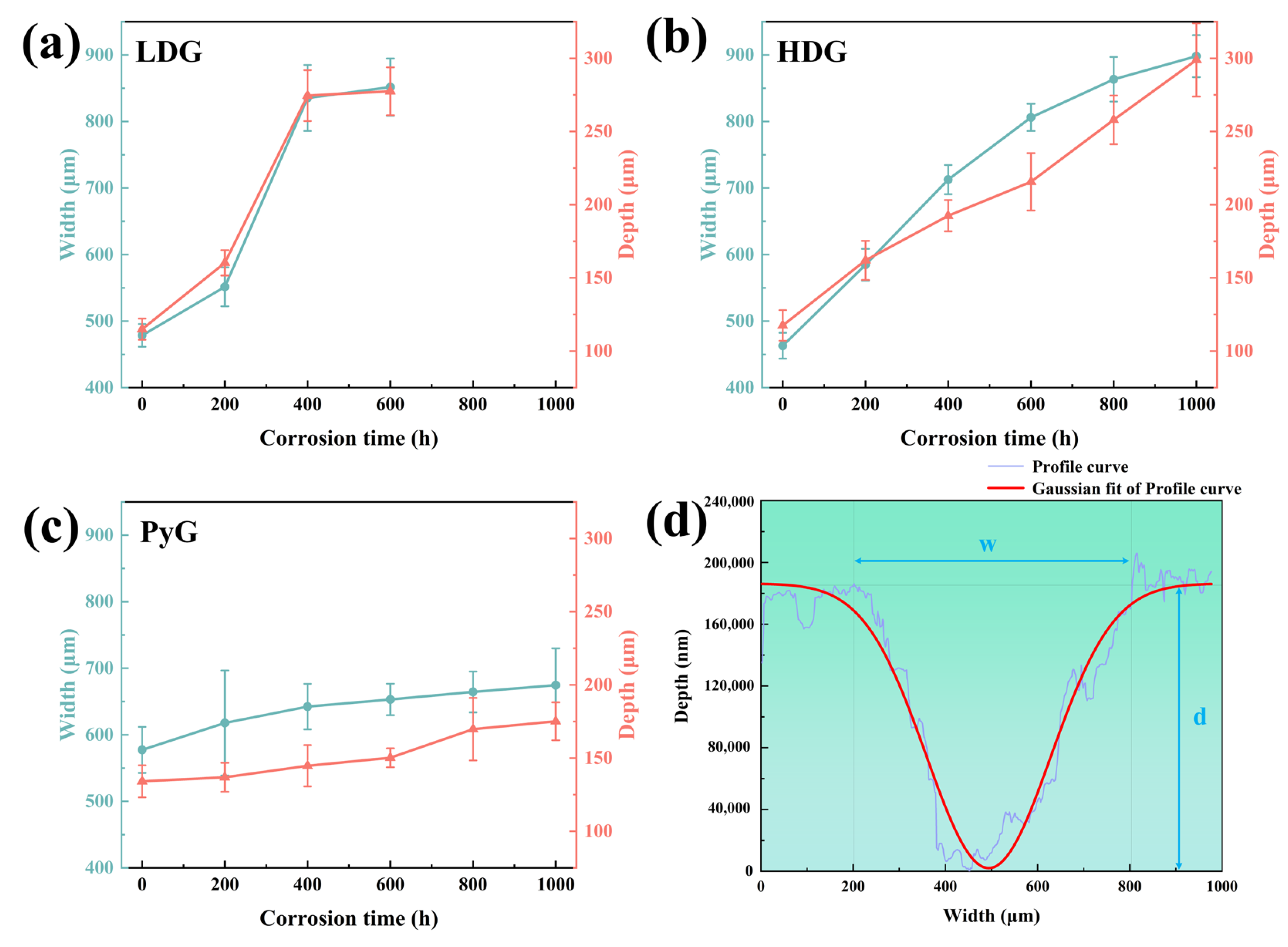
3.2. Microstructure and Mechanical Properties

Figure 4 shows SEM images of the graphite surface before and after corrosion by molten CuSn alloy. LDG and HDG are fabricated by applying uniform high pressure to compress graphite powder. As a result, the surface of the pristine sample typically contains numerous pores and microcracks, as shown in Figure 4a,b. These features serve as active sites for molten metal infiltration and subsequent graphite corrosion. According to Zhao He et al. [19], molten metal penetration into graphite is influenced by porosity, temperature, pressure, and exposure time. Under identical temperature and pressure conditions, the degree of metal penetration positively correlates with both graphite porosity and exposure time. For both LDG and HDG, the pores and microcracks on the graphite surface were filled with metal particles after the corrosion experiment, and the carbon particles were detached from the graphite surface, resulting in the expansion and deepening of the surface pores. LDG exhibited the most severe corrosion damage, with wide pores caused by corrosion clearly visible on the sample after 400 h of corrosion, as depicted in Figure 4a. In contrast, HDG experienced less corrosion damage than LDG due to its superior density and lower porosity, with wide pores forming later on its surface. After 800 h, the surface of HDG developed a honeycomb-like porous structure. PyG exhibits a high degree of graphitization and a nearly non-porous layered structure due to its chemical vapor deposition (CVD) manufacturing process. However, defects in the manufacturing process introduced local fracture layers and microcracks in PyG, which serve as active sites for the corrosion of molten CuSn alloys. The corrosion of PyG is non-uniform. At the surface structural defects, corrosion forms regional pores or even fracture layers, as shown in Figure 4c. Additionally, the corrosion on the PyG surface is uneven, as illustrated by the SEM image of a larger area in Figure 5. Wide pores readily form at fracture layers or micro-crack sites on the sample, while the corrosion at flat, defect-free areas is significantly less severe.
The cross-sectional SEM images of the three graphite samples after corrosion are shown in Figure 6. The maximum depth of the internal metal particles from the contact surface is marked in the figures. The penetration depth of the molten CuSn alloy into LDG and HDG increased with exposure time. After 600 h, the maximum metal penetration depth in LDG was approximately 162 μm, whereas in HDG, it was about 82 μm, roughly half of that in LDG. After 1000 h, the metal penetration depth in HDG reached approximately 186 μm. In the LDG and HDG samples, a significant amount of large metal particles accumulated in the near-surface layer, where the graphite suffered more severe corrosion, resulting in the fragmentation of graphite particles into finer pieces or even powders. Fewer metal particles and less pronounced corrosion were observed in the deeper regions, farther from the surface. The nearly non-porous layered structure significantly prevents the penetration of molten CuSn alloy into PyG. Even after 1000 h of exposure, corrosion-induced pores only form at the outermost structural defects. No metal particles or signs of corrosion were observed in the far surface layers. This suggests that the faultless layered graphite structure can effectively hinder the penetration of the molten CuSn alloy into the deeper graphite layers.
Corrosion of structural materials by molten metals generally occurs through the dissolution of material components, chemical reactions, mechanical effects, and interatomic interactions [28]. Depending on the material composition and environmental conditions, one or more of these corrosion processes may occur simultaneously. The degree of graphite corrosion observed by SEM correlates with the metal penetration content and depth. Studies have shown that molten metal infiltration generates stress, which can cause corrosion damage to the material [29,30]. As molten metal penetrates graphite, it converges to form particles, and the resulting stress concentration further aggravates the corrosion damage of the graphite structure. This is consistent with the observation that metal particles near the graphite surface are larger, and the corrosion damage in these regions is more serious. As shown in Figure 4d, EDS elemental analysis of the corroded graphite samples, such as PyG-600h, revealed the presence of only metals (Cu: 0.08 at.%, Sn: 0.09 at.%) and carbon (C: 99.83 at.%), with no detectable impurity elements. Therefore, the morphological changes in graphite can be preliminarily attributed to the stress generated by the molten CuSn alloy in the graphite structure.
In this study, the optical surface morphology and roughness of graphite samples were measured using a three-dimensional optical profilometer. The root mean square roughness (Rq) of the sample surface was calculated using the equation:
R q = i = 1 n Z i Z ¯ 2 n
where Zi represents the height of each point, Z ¯ is the average height of all points, and n is the number of data points in the image area. The total height of the profile (Rt) was indicated directly above the right scale in the 3D optical profilometry map in Figure 7a–c. To minimize the influence of measurement location, measurements were taken at the sample center and five surrounding areas, and the values were then averaged.
The 3D optical profilometry map shows that all three graphite samples were corroded by molten CuSn alloy, causing significant surface defects. Morphologies of LDG and HDG show that corrosion caused the detachment of graphite surface layers as carbon particles, leaving wide pores. PyG appears to have undergone pitting corrosion by molten CuSn alloy, with larger and deeper pore defects forming at the surface. These morphological characteristics are aligned with those observed by SEM. The Rq of the samples is presented in Figure 7d. After 1000 h of corrosion by molten CuSn alloy, the roughness of all three graphite samples increased. The roughness of LDG and HDG continued to increase with exposure time, while PyG’s roughness initially increased and then decreased, likely due to the expansion and coalescence of surface pores. The primary cause of the increased surface roughness of graphite is pore expansion and the detachment of carbon particles induced by corrosion. Furthermore, during the separation of graphite and metal after the experiment, the molten metal removed some loose carbon particles from the graphite matrix, further contributing to the increase in surface roughness.
Scratch hardness tests were conducted on graphite samples using an automated scratch tester to evaluate changes in mechanical properties before and after corrosion [31,32]. Shore hardness or nanoindentation tests were not employed due to the limitations in sample size and surface roughness, which prevented obtaining accurate results. The automated scratch tester operated in constant-load sliding mode to create a 3 mm scratch on the graphite surface under a 20 N load. The loading and unloading rates were set to 20 N/min, allowing a single reciprocating motion. The scratch profile curve was measured using a profilometer, and its width and depth were determined through Gaussian fitting, as shown in Figure 8. Five equidistant points along each scratch were measured. The scratch hardness of the graphite samples was calculated using the formula:
H s = F A
where Hs is the scratch hardness, F is the applied load, and A is the area of the scratch groove cross-section, which was approximated as an isosceles triangle during calculations. The results of the scratch hardness calculations are shown in Figure 7f. The hardness of LDG decreases most rapidly with increasing exposure time, indicating the most significant reduction in mechanical properties. Compared to the LDG-400h sample, the LDG-600h sample exhibits a little change in hardness, primarily due to the exfoliation of the carbon particles caused by severe surface corrosion of the graphite matrix. Small graphite flakes were observed splattering during scratch acquisition in PyG, resulting in higher scratch width and depth measurements and lower hardness values. However, PyG exhibited the slowest rate of hardness decay, demonstrating its superior ability to maintain mechanical properties under corrosion by molten CuSn alloy. The hardness degradation of HDG was intermediate between that of LDG and PyG. The scratch hardness test of graphite shows that corrosion by molten CuSn alloy degrades its mechanical properties. The extent and rate of mechanical property degradation significantly affect the application of structural materials. The high degree of graphitization, layered structure, and high density of PyG enhance its long-term resistance to penetration and corrosion by molten CuSn alloy. The manufacturing method of HDG is identical to that of LDG, and its low porosity, which corresponds to high density, leads to a slight improvement in corrosion resistance after the same corrosion period.

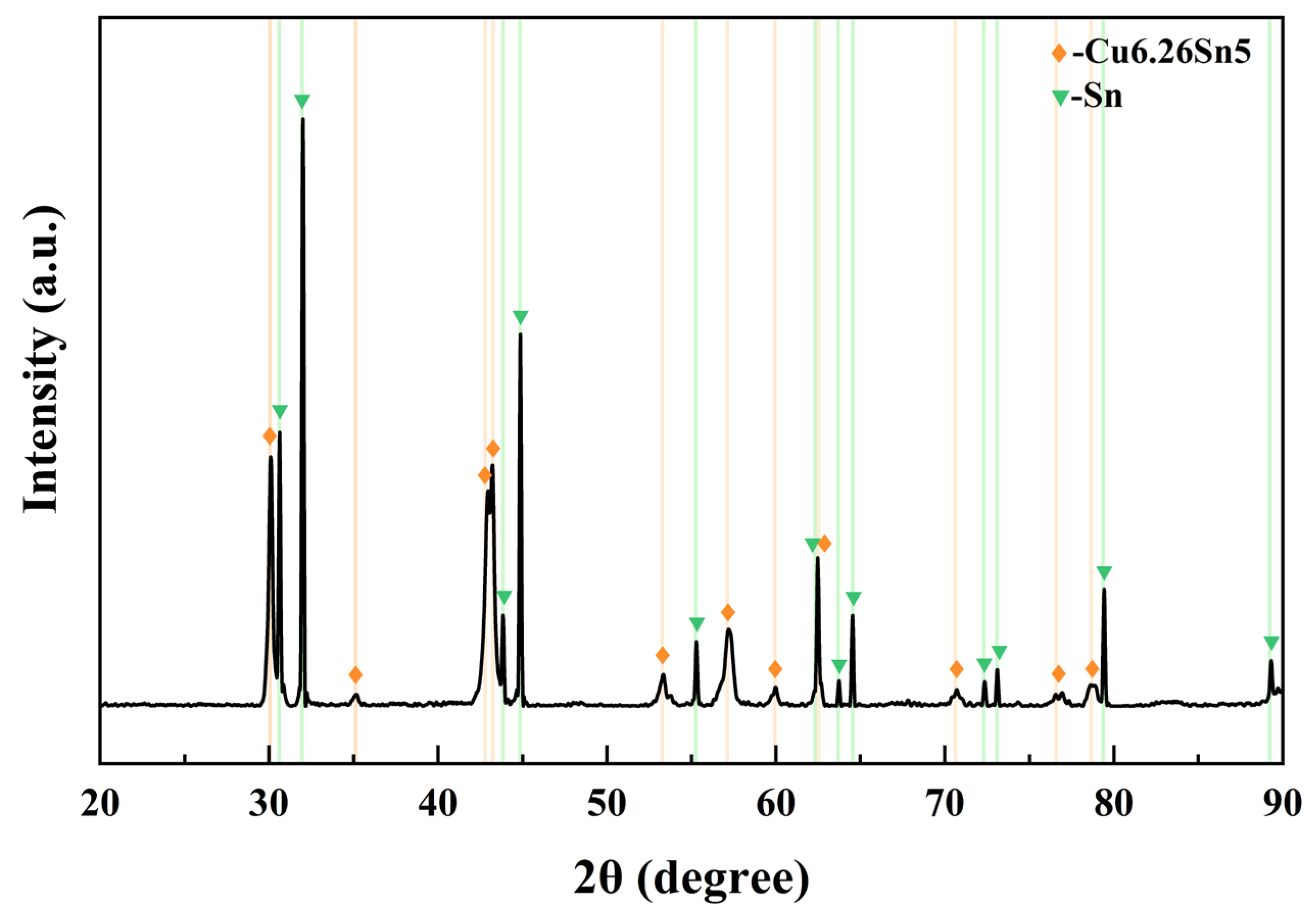
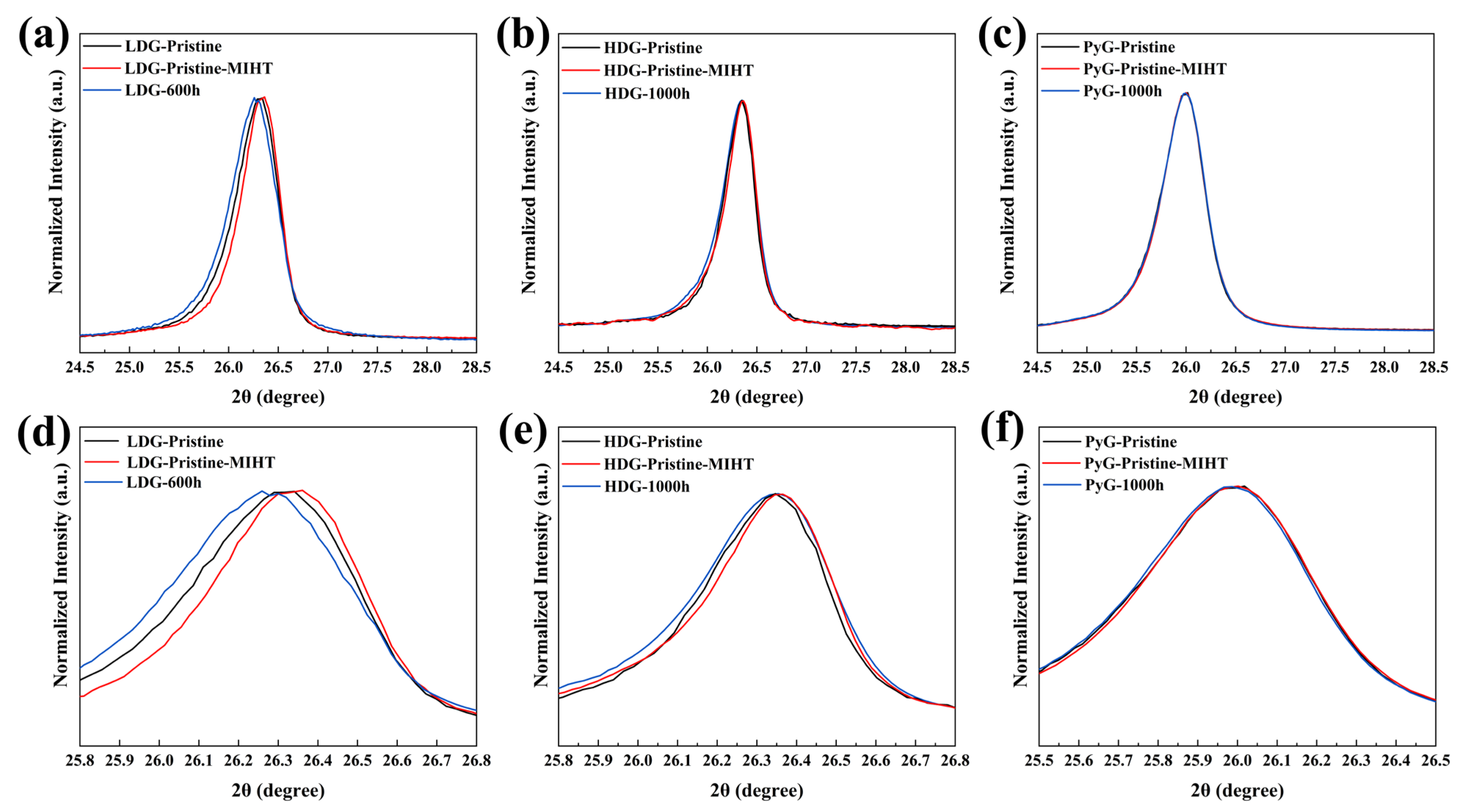
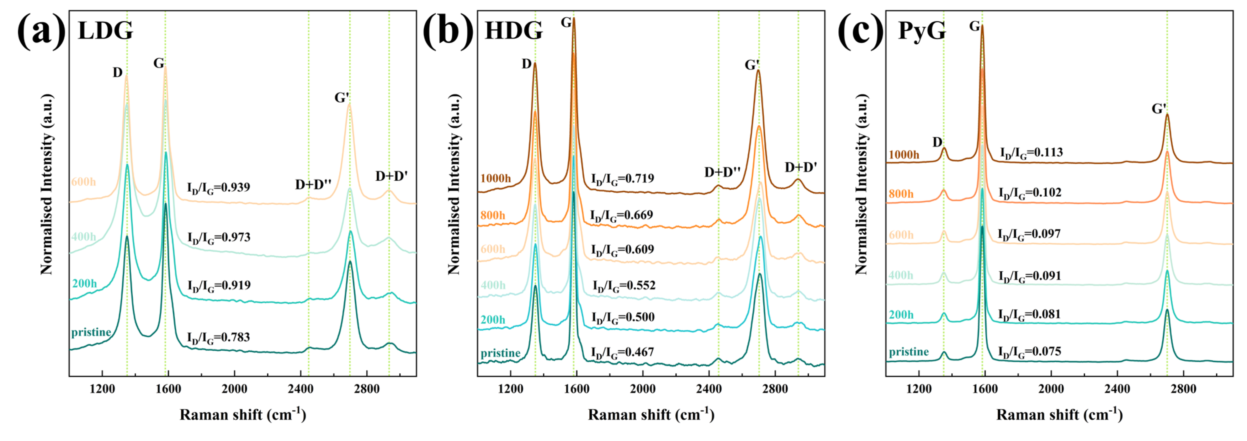
3.3. X-Ray Diffraction and Raman Spectroscopy Characterization

XRD patterns were measured to investigate the phase composition and crystal structure changes in the three graphite samples after corrosion, as shown in Figure 9. The corresponding graphite characteristic lattice plane has been marked in the figures. In addition to the characteristic graphite peaks in the XRD patterns of LDG and HDG, peaks corresponding to metallic Sn and the intermetallic compound Cu6.26Sn5 appeared after corrosion. These peaks corresponded to the SEM morphology of metal particles filling the graphite pores. No diffraction peaks for metals or compounds are observed in the XRD pattern of PyG. This may be because the corrosion of PyG occurs locally, and the X-ray measurement detects the uncorroded area rather than the pores formed by the corrosion of molten CuSn alloy. After 1000 h of corrosion, no diffraction peaks for Cu-C, Sn-C, or intercalation compounds were detected in the XRD patterns of the three graphite samples.
After the corrosion of LDG and HDG by molten CuSn alloy, the intensity of the (002) diffraction peaks for both samples significantly decreased, indicating a reduction in graphite crystallinity. This suggests that graphite may transform into amorphous carbon during the corrosion process. The mean dimension of crystallite perpendicular to the (002) diffracting plane (Lc) was calculated using Equations (4) and (5) [33,34] to reflect changes in the graphite crystal structure after corrosion.
L c = k λ β cos θ 002 ,
β = β 002 2 β I 2
where k is a constant (0.89), λ is the X-ray wavelength (0.15418 nm, Cu, Kα), β002 and θ002 represent the FWHM and the corresponding Bragg angle of the graphite (002) diffraction peak, respectively, and βI is the instrument broadening (measured in this work as 0.1047°). The Lc calculation results are shown in Figure 9d, and the Lc of the graphite samples fluctuated within a certain range after corrosion. Studies have shown that high temperatures can promote grain growth and defect healing in materials, leading to an increase in grain size [35]. During cooling, the mismatch in the thermal expansion coefficients of metal and graphite generates compressive stress, which closes the Mrozowski cracks in artificial graphite and increases Lc [19,36]. The decrease in Lc may be linked to the corrosion degradation in the graphite crystal structure, which will be further discussed in the next section. LDG suffered the most severe corrosion in this research and decreased Lc noticeably. After 600 h, the severely corroded graphite particles on the surface of LDG completely detached. XRD detected a region with lower corrosion in the inner layer, and Lc showed a slight recovery. Due to the relatively mild corrosion of HDG and PyG, as well as the challenges in maintaining consistent sample areas during measurement, deviations were observed in the calculated Lc values. The Lc value of PyG remained within the range of 16.1 ± 0.4 nm, while the Lc value of HDG remained within the range of 22.7 ± 0.6 nm.
To investigate the effect of metal on the crystal structure of graphite during heating and cooling, a metal infiltration and heat treatment (MIHT) comparative experiment was conducted. The control experiment setup was the same as the corrosion experiment, except that cooling occurred immediately after heating to 1100 °C. Figure 10 compares the (002) diffraction peaks of the pristine samples of the three graphite before and after the MIHT experiment under normalized intensity and includes the (002) diffraction peaks of the graphite samples with the maximum corrosion time. The results show that after the MIHT experiment, the (002) diffraction peaks of LDG and HDG shift slightly to a larger 2θ angle, while the FWHMs decrease. This suggests that some structural defects in the graphite crystals were healed during the MIHT process. In contrast, compared to the pristine sample, the (002) diffraction peaks of the corroded sample shift to the left, and its FWHMs increase. This indicates that corrosion damage caused by the molten CuSn alloy generates numerous structural defects in the graphite crystal structure, which could not be fully healed during the heating and cooling process [37]. The more porous structure of LDG results in greater metal penetration and retention. Therefore, the defect healing (indicated by the diffraction peaks shifting to the right) caused by high temperature or thermal expansion coefficient mismatch between the metal and graphite is more pronounced. The increase in defect content caused by corrosion (indicated by the diffraction peaks shifting to the left) is also more pronounced. The diffraction peak shifts in HDG are smaller than that of LDG, and the change in structural defect content is also less pronounced. After the MIHT experiment and 1000 h corrosion, the position and FWHM of the (002) diffraction peaks of PyG remain almost unchanged, and the content of crystal defects shows minimal variation. The XRD characterization results demonstrate that no chemical corrosion occurred, which is consistent with previous studies [38,39]. However, the shift in the diffraction peak position, changes in crystallinity, and Lc suggest that the crystal structure may have been damaged by the molten CuSn alloy, leading to an increase in defect content.
Laser Raman spectroscopy is an effective tool for characterizing the structural order of carbon materials. The Raman spectrum of defect-free graphite contains two sharp bands: the G band near 1580 cm−1 and the G’ band near 2700 cm−1. The appearance of the D band near 1350 cm−1 indicates structural defects in the material [40]. As structural defects in graphite increase, the intensity of the D peak also strengthens, while the G peak may undergo a slight shift or broadening. The intensity ratio of the D and G bands (ID/IG) is commonly used to represent the structural order of carbon materials. In this research, a 532 nm laser was used as the excitation source to test the graphite before and after corrosion. The intensity-normalized Raman spectra are shown in Figure 11, and the ID/IG values for each sample are directly marked in the figures. The Raman spectra show the three main bands, D, G, and G’, indicating that the graphite structures contain defects. Additionally, two low-intensity bands, D + D’ and D + D’’, obviously appeared on either side of the G’ band in the Raman spectra of LDG and HDG. Research indicates that these bands only appear when graphite has a high density of structural defects [41]. As the exposure time of graphite in molten CuSn alloy increased, the number of corrosion-induced defects increased, leading to a rise in the ID/IG ratio. After 1000 h of corrosion, the structure of all three graphite samples became more disordered due to the accumulation of defects. The D band intensity and ID/IG of LDG samples were generally higher than those of HDG and PyG, indicating that LDG materials have significantly higher degrees of structural disorder and defect content. PyG had the most ordered structure among the three graphite materials, and the results showed that it was also the least corroded. By Raman spectroscopy, the graphite samples with a more ordered structure suffered less corrosion in the molten CuSn alloy.

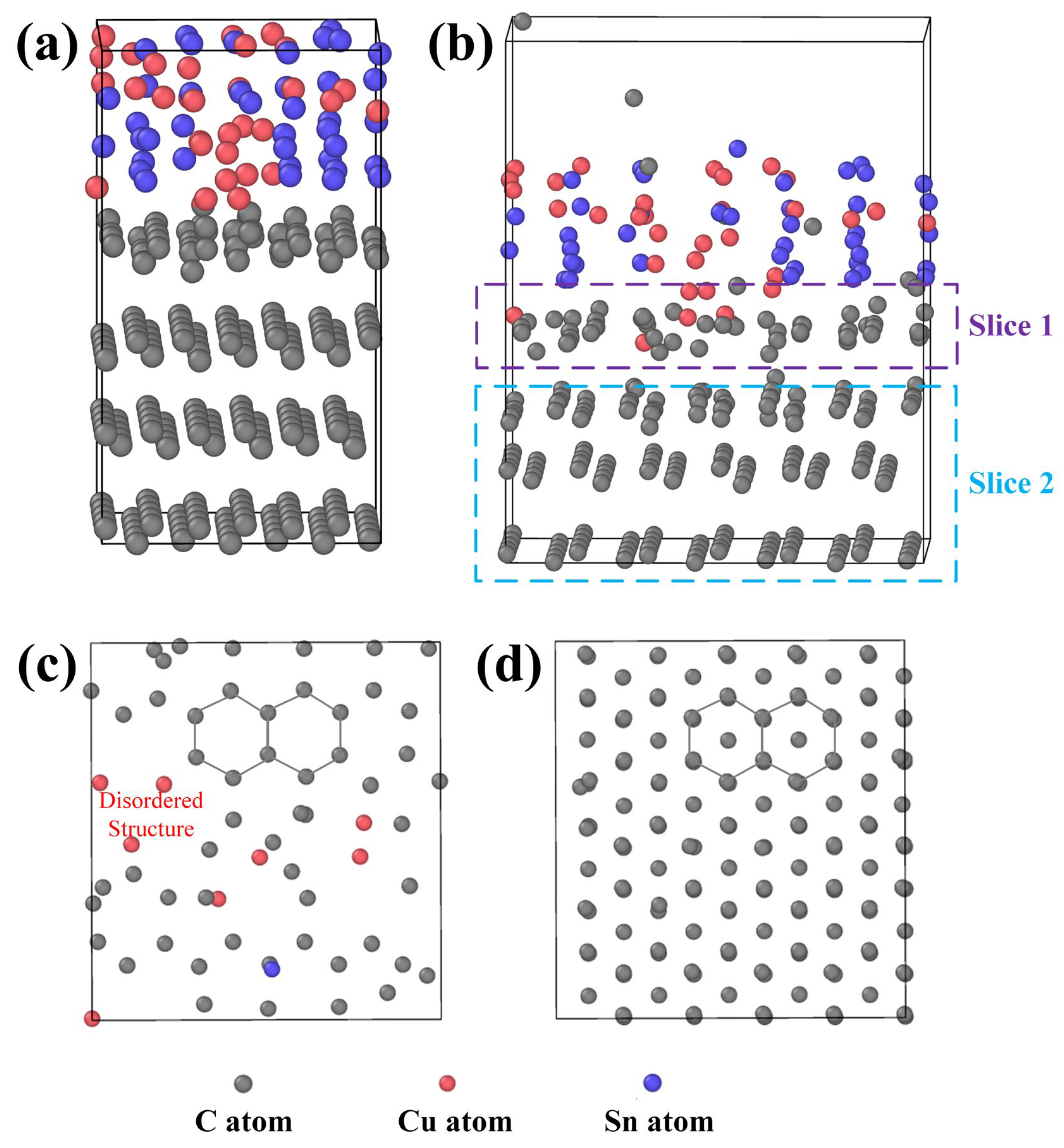
3.4. Simulation and Corrosion Mechanism Analysis

In the previous discussion, we initially attributed the corrosion of graphite in molten CuSn alloy to the stress effect induced by metal penetration and aggregation. LDG and HDG are both porous graphite structures fabricated by isostatic pressing, where the effect of stress on the internal pores is significant. PyG, fabricated by CVD, is a dense, layered structure. Metal penetration into the structure is difficult, and the effect of stress is minimal. After the experiment, corrosion characteristics resembling metal pitting were observed on the surface of PyG, and Raman spectroscopy confirmed that the structure of PyG became more disordered. Therefore, the corrosion of graphite materials in molten CuSn alloy is not solely caused by stress. To further investigate the damage mechanism of molten CuSn alloy on the graphite structure, a graphite–CuSn alloy model was established using LAMMPS. The molten CuSn was equilibrated under the NPT ensemble with a relaxation time of 0.5 ps. The initial configuration was created by connecting solid graphite with molten CuSn samples. The total size of the solid–liquid structure was 25 × 25 × 53, containing 3292 atoms. The initial state of the solid–liquid system model is shown in Figure 12a. The time step for the LAMMPS simulation was set to 1.0 fs, with the Nose–Hoover thermostat and Parrinello–Rahman barostat used to control the temperature (1373 K) and pressure (131 kPa). Periodic boundary conditions were applied in all three spatial directions.
After 1.0 ps in the thermal bath, the equilibrated solid–liquid system is shown in Figure 12b, and the complete video of the atomic motion process is shown in the Supplementary Information. Surprisingly, the intact C atom lattice structure at the solid–liquid interface becomes defective due to interactions with Cu and Sn atoms. Some Cu atoms infiltrate the carbon lattice planes, displacing adjacent carbon atoms and disrupting the ordered arrangement. Additionally, carbon atoms diffuse into the molten CuSn alloy, suggesting that the graphite structure transforms into amorphous carbon. The graphite structure was sliced for observation, as shown in Figure 12c,d. The damage to the graphite structure caused by Cu and Sn atoms occurs primarily at the contact interface. Carbon atoms deeper within the structure, which are unaffected by the metal atoms, retain their original arrangement. At the solid–liquid contact interface, atomic collisions cause some carbon atoms to displace, resulting in defect formation. Metal atoms occupy defect sites, causing the defects to propagate and ultimately leading to structural collapse. The MD simulation results confirmed the increased disorder in the graphite crystal structure, as detected by XRD and Raman spectroscopy and aligned with the formation of pores observed by SEM. Furthermore, the corrosion effect of metal atoms could be more pronounced for graphite materials with structural defects. Thus, the damage to the graphite atomic structure by metal atoms at high temperatures provides an explanation for graphite corrosion in molten CuSn alloy in addition to the stress effect.
Experimental and simulation results demonstrate that atomic thermal motion and stress from metal penetration are the primary causes of graphite corrosion in molten CuSn alloy. At 1100 °C, the thermal motion of Cu and Sn atoms disrupts the ordered arrangement of carbon atoms, leading to a layer-by-layer disordering of the graphite structure. Throughout the experiment, atomic thermal motion continuously caused corrosion damage to the three graphite structures. The corrosion of this microstructure is typically slow but intensifies at graphite’s inherent structural defects, forming local pores, resembling pitting corrosion. In contrast to the nearly non-porous layered graphite (e.g., PyG) produced by the CVD method, porous isostatically pressed graphite (e.g., LDG, HDG) also experiences stress due to molten CuSn alloy penetration during corrosion. The tightly packed graphite particles are damaged by stress within the pores, leading to loosening, deformation, and even fragmentation. The corrosion effect caused by this stress is highly significant and directly related to the density and porosity of graphite. Therefore, LDG suffered the most serious corrosion in the experiment, while PyG had relatively better corrosion resistance. Figure 13 illustrates the corrosion mechanism of molten CuSn alloy on graphite in detail. The process can be summarized as follows: (1) Molten metal wets the graphite surface at high temperatures, initiating material interaction at the interface and primarily causing atomic structural damage in graphite due to thermal motion. (2) The metal infiltrates and accumulates within the graphite, leading to localized stress concentration. (3) Stress generated by molten metal infiltration into graphite pores and defects accelerates pore expansion and material degradation, causing carbon particles to loosen and detach from the graphite matrix. Notably, the stress corrosion of PyG is minimal due to its non-porous structure. PyG could be considered to be corroded solely by atomic thermal motion.

4. Conclusions

This work systematically investigated the corrosion behavior of molten CuSn alloy on three graphite materials for up to 1000 h at 1100 °C. The results show that all graphite samples display the following corrosion characteristics: increased pore size, increased surface roughness, decreased hardness, and mass loss. At the start of the corrosion test, LDG first exhibited pore expansion and carbon particle shedding. After 800 h, with a mass loss of up to 60.09%, the graphite block disintegrated into powder, and its hardness significantly decreased. HDG, with superior density and porosity, also exhibited carbon particle shedding after prolonged corrosion. The formation of honeycomb-like carbon particles after 800 h suggests that HDG is severely corroded by molten CuSn alloy, and after extended corrosion, it will likely collapse in a manner similar to LDG. PyG, with its nearly non-porous layered structure, effectively blocks molten CuSn alloy infiltration, resulting in the least corrosion, with minimal mass loss and hardness degradation.
Macroscopic corrosion of graphite by molten CuSn alloy at high temperatures is driven by stress effects. Stress arises from molten metal infiltration into the graphite pore structure, followed by metal transmission and aggregation within the pores, significantly affecting porous graphite. Additionally, the thermal motion of Cu and Sn atoms disturbs the ordered graphite microstructure layer by layer, causing microstructural corrosion. Micro-corrosion generally occurs at the contact interface between graphite and molten CuSn alloy, resulting in slow and relatively mild corrosion. However, inherent structural defects (e.g., dislocations, vacancies) in artificial graphite exacerbate the corrosion, leading to severe local corrosion and conversion into disordered carbon materials.
The graphite material undergoes both macroscopic and microscopic corrosion effects in molten CuSn alloy at 1100 °C, resulting in structural corrosion and performance degradation. The extent of corrosion depends on the manufacturing methods and processes of graphite. Graphite with a denser structure, lower porosity, and fewer defects exhibits better corrosion resistance. In this study, the corrosion resistance of the three graphite materials follows this order: LDG < HDG < PyG. The findings of this work shed light on selecting suitable graphite materials as furnace wall components for hydrogen production via molten metal-catalyzed methane pyrolysis, contributing to the development of the hydrogen production industry.

Supplementary Materials

The following supporting information can be downloaded at https://www.mdpi.com/article/10.3390/pr13020381/s1. Video S1: The video of the complete atomic motion process of the solid–liquid system composed of molten CuSn alloy and graphite.

Author Contributions

Conceptualization, Z.Y., J.W., and F.G.; data curation, Z.C., Z.Y., and X.L.; investigation, Z.C., Z.Y., X.L., H.T., H.G., J.W., and F.G.; software, H.T.; supervision, F.G.; visualization, Z.C.; writing—original draft, Z.C.; writing—review and editing, H.G., F.G., and Z.Y. All authors have read and agreed to the published version of the manuscript.

Funding

This research was funded by the National Key Research and Development Program of China (Grant No. 2022YFE03130000), and the National Natural Science Foundation of China (Grant No. 11905151).

Data Availability Statement

Data are contained within the article and Supplementary Materials.

Conflicts of Interest

The authors declare no conflicts of interest.

Nomenclature

HDGHigh-density graphite
ID/IGThe intensity ratio of the D and G bands of Raman spectroscopy
LcThe mean dimension of crystallite perpendicular to the (002) diffracting plane
LDGLow-density graphite
MDMolecular dynamics
MIHTMetal infiltration and heat treatment
PyGPyrolytic graphite
RqThe root mean square roughness
RtThe total height of the profile

References

  1. Chen, L.; Song, Z.; Zhang, S.; Chang, C.-K.; Chuang, Y.-C.; Peng, X.; Dun, C.; Urban, J.J.; Guo, J.; Chen, J.L.; et al. Ternary NiMo-Bi liquid alloy catalyst for efficient hydrogen production from methane pyrolysis. Science 2023, 381, 857. [Google Scholar] [CrossRef] [PubMed]
  2. Muradov, N. Low to near-zero CO2 production of hydrogen from fossil fuels: Status and perspectives. Int. J. Hydrogen Energy 2017, 42, 14058. [Google Scholar] [CrossRef]
  3. Qian, J.X.; Chen, T.W.; Enakonda, L.R.; Liu, D.B.; Basset, J.-M.; Zhou, L. Methane decomposition to pure hydrogen and carbon nano materials: State-of-the-art and future perspectives. Int. J. Hydrogen Energy 2020, 45, 15721. [Google Scholar] [CrossRef]
  4. Keipi, T.; Tolvanen, K.E.S.; Tolvanen, H.; Konttinen, J. Thermo-catalytic decomposition of methane: The effect of reaction parameters on process design and the utilization possibilities of the produced carbon. Energy Convers. Manag. 2016, 126, 923. [Google Scholar] [CrossRef]
  5. Abánades, A.; Rathnam, R.K.; Geißler, T.; Heinzel, A.; Mehravaran, K.; Müller, G.; Plevan, M.; Rubbia, C.; Salmieri, D.; Stoppel, L.; et al. Development of methane decarbonisation based on liquid metal technology for CO2-free production of hydrogen. Int. J. Hydrogen Energy 2016, 41, 8159. [Google Scholar] [CrossRef]
  6. Geißler, T.; Abánades, A.; Heinzel, A.; Mehravaran, K.; Müller, G.; Rathnam, R.K.; Rubbia, C.; Salmieri, D.; Stoppel, L.; Stückrad, S.; et al. Hydrogen production via methane pyrolysis in a liquid metal bubble column reactor with a packed bed. Chem. Eng. J. 2016, 299, 192. [Google Scholar] [CrossRef]
  7. Noh, Y.-G.; Lee, Y.J.; Kim, J.; Kim, Y.K.; Ha, J.; Kalanur, S.S.; Seo, H. Enhanced efficiency in CO2-free hydrogen production from methane in a molten liquid alloy bubble column reactor with zirconia beads. Chem. Eng. J. 2022, 428, 131095. [Google Scholar] [CrossRef]
  8. Patlolla, S.R.; Katsu, K.; Sharafian, A.; Wei, K.; Herrera, O.E.; Mérida, W. A review of methane pyrolysis technologies for hydrogen production. Renew. Sustain. Energy Rev. 2023, 181, 113323. [Google Scholar] [CrossRef]
  9. Geißler, T.; Plevan, M.; Abánades, A.; Heinzel, A.; Mehravaran, K.; Rathnam, R.K.; Rubbia, C.; Salmieri, D.; Stoppel, L.; Stückrad, S.; et al. Experimental investigation and thermo-chemical modeling of methane pyrolysis in a liquid metal bubble column reactor with a packed bed. Int. J. Hydrogen Energy 2015, 40, 14134. [Google Scholar] [CrossRef]
  10. Leal Pérez, B.J.; Medrano Jiménez, J.A.; Bhardwaj, R.; Goetheer, E.; van Sint Annaland, M.; Gallucci, F. Methane pyrolysis in a molten gallium bubble column reactor for sustainable hydrogen production: Proof of concept & techno-economic assessment. Int. J. Hydrogen Energy 2021, 46, 4917. [Google Scholar]
  11. Miyakawa, Y.; Kondo, M. Corrosion behaviors of various steels and nickel-based alloys in liquid Sn media. Nucl. Mater. Energy 2022, 30, 101154. [Google Scholar] [CrossRef]
  12. Meetham, G.W. High-temperature materials—A general review. J. Mater. Sci. 1991, 26, 853. [Google Scholar] [CrossRef]
  13. Nickel, H. High-temperature resistant materials and structural ceramics for use in high-temperature reactor and fusion reactor plants-requirements for modern physico-chemical analysis. Microchim. Acta 1987, 91, 5. [Google Scholar] [CrossRef]
  14. Zhou, X.-W.; Yang, Y.; Song, J.; Lu, Z.-M.; Zhang, J.; Liu, B.; Tang, Y.-P. Carbon materials in a high temperature gas-cooled reactor pebble-bed module. New Carbon Mater. 2018, 33, 97. [Google Scholar] [CrossRef]
  15. Srinivasan, M. Design and manufacture of graphite components for 21st century small modular reactors. Nucl. Eng. Des. 2022, 386, 111568. [Google Scholar] [CrossRef]
  16. He, Z.; Lian, P.; Song, J.; Zhang, D.; Liu, Z.; Guo, Q. Microstructure and properties of fine-grained isotropic graphite based on mixed fillers for application in molten salt breeder reactor. J. Nucl. Mater. 2018, 511, 318. [Google Scholar] [CrossRef]
  17. Liu, Q.; Leng, B.; Qiu, J.; Yin, H.; Lin, J.; Tang, Z. Effect of graphite particles in molten LiF-NaF-KF eutectic salt on corrosion behaviour of GH3535 alloy. Corros. Sci. 2020, 168, 108581. [Google Scholar] [CrossRef]
  18. Zhang, C.; He, Z.; Gao, Y.; Tang, H.; Qi, W.; Song, J.; Zhou, X. The effect of molten FLiNaK salt infiltration on the strength of graphite. J. Nucl. Mater. 2018, 512, 37. [Google Scholar] [CrossRef]
  19. He, Z.; Liu, Z.; Marrow, T.J.; Song, J. The infiltration behavior and chemical compatibility of molten lead-bismuth eutectic in nuclear graphite at elevated temperature. J. Nucl. Mater. 2021, 550, 152921. [Google Scholar] [CrossRef]
  20. Sure, J.; Ravi Shankar, A.; Ramya, S.; Mallika, C.; Kamachi Mudali, U. Corrosion behaviour of carbon materials exposed to molten lithium chloride–potassium chloride salt. Carbon 2014, 67, 643. [Google Scholar] [CrossRef]
  21. Scheiblehner, D.; Neuschitzer, D.; Wibner, S.; Sprung, A.; Antrekowitsch, H. Hydrogen production by methane pyrolysis in molten binary copper alloys. Int. J. Hydrogen Energy 2023, 48, 6233. [Google Scholar] [CrossRef]
  22. Scheiblehner, D.; Antrekowitsch, H.; Neuschitzer, D.; Wibner, S.; Sprung, A. Hydrogen Production by Methane Pyrolysis in Molten Cu-Ni-Sn Alloys. Metals 2023, 13, 1310. [Google Scholar] [CrossRef]
  23. López, G.A.; Mittemeijer, E.J. The solubility of C in solid Cu. Scr. Mater. 2004, 51, 1–5. [Google Scholar] [CrossRef]
  24. Oden, L.L.; Gokcen, N.A. Cu-C and Al-Cu-C phase diagrams and thermodynamic properties of c in the alloys from 1550 °C to 2300 °C. Metall. Trans. B 1992, 23, 453. [Google Scholar] [CrossRef]
  25. Oden, L.L.; Gokcen, N.A. Sn-C and Al-Sn-C phase diagrams and thermodynamic properties of C in the alloys: 1550 °C to 2300 °C. Metall. Trans. B 1993, 24, 53. [Google Scholar] [CrossRef]
  26. Zaghloul, N.; Kodama, S.; Sekiguchi, H. Hydrogen Production by Methane Pyrolysis in a Molten-Metal Bubble Column. Chem. Eng. Technol. 2021, 44, 1986. [Google Scholar] [CrossRef]
  27. Qiao, C.; Che, J.; Wang, J.; Wang, X.; Qiu, S.; Wu, W.; Chen, Y.; Zu, X.; Tang, Y. Cost effective production of high quality multilayer graphene in molten Sn bubble column by using CH4 as carbon source. J. Alloys Compd. 2023, 930, 167495. [Google Scholar] [CrossRef]
  28. Manly, W.D. Fundamentals of Liquid Metal Corrosion. Corrosion 1956, 12, 46. [Google Scholar] [CrossRef]
  29. He, Z.; Gao, L.; Wang, X.; Zhang, B.; Qi, W.; Song, J.; He, X.; Zhang, C.; Tang, H.; Xia, H.; et al. Improvement of stacking order in graphite by molten fluoride salt infiltration. Carbon 2014, 72, 304. [Google Scholar] [CrossRef]
  30. Zeng, Y.; Xiong, X.; Wang, D.; Wu, L.; Chen, Z.; Sun, W.; Wang, Y.; Xiao, P. High temperature corrosion of carbon/carbon composites in Zr–Ti melts during liquid metal infiltration. Corros. Sci. 2015, 98, 98. [Google Scholar] [CrossRef]
  31. Liu, J.; Zeng, Q.; Xu, S. The state-of-art in characterizing the micro/nano-structure and mechanical properties of cement-based materials via scratch test. Constr. Build. Mater. 2020, 254, 119255. [Google Scholar] [CrossRef]
  32. Liu, J.; Zeng, Q.; Xu, S. Is scratch test proper to characterize microstructure and mechanical properties of cement-based materials? The effects of loading level and routine. Cem. Concr. Res. 2020, 133, 106072. [Google Scholar] [CrossRef]
  33. Li, K.; Liu, Q.; Cheng, H.; Hu, M.; Zhang, S. Classification and carbon structural transformation from anthracite to natural coaly graphite by XRD, Raman spectroscopy, and HRTEM. Spectrochim. Acta Part A Mol. Biomol. Spectrosc. 2021, 249, 119286. [Google Scholar] [CrossRef] [PubMed]
  34. Iwashita, N.; Park, C.R.; Fujimoto, H.; Shiraishi, M.; Inagaki, M. Specification for a standard procedure of X-ray diffraction measurements on carbon materials. Carbon 2004, 42, 701. [Google Scholar] [CrossRef]
  35. Krishna, R.; Wade, J.; Jones, A.N.; Lasithiotakis, M.; Mummery, P.M.; Marsden, B.J. An understanding of lattice strain, defects and disorder in nuclear graphite. Carbon 2017, 124, 314. [Google Scholar] [CrossRef]
  36. Liu, D.; Gludovatz, B.; Barnard, H.S.; Kuball, M.; Ritchie, R.O. Damage tolerance of nuclear graphite at elevated temperatures. Nat. Commun. 2017, 8, 15942. [Google Scholar] [CrossRef]
  37. Dolabella, S.; Borzì, A.; Dommann, A.; Neels, A. Lattice Strain and Defects Analysis in Nanostructured Semiconductor Materials and Devices by High-Resolution X-Ray Diffraction: Theoretical and Practical Aspects. Small Methods 2021, 6, 2100932. [Google Scholar] [CrossRef]
  38. Nikonova, R.M.; Lad’yanov, V.V. Contact interaction of metal melts with fullerite and graphite. J. Mater. Res. Technol. 2020, 9, 12559. [Google Scholar] [CrossRef]
  39. Liu, S.; Li, Q.; Chen, Y.; Zhang, F. Carbon-coated copper–tin alloy anode material for lithium ion batteries. J. Alloys Compd. 2009, 478, 694. [Google Scholar] [CrossRef]
  40. Pimenta, M.A.; Dresselhaus, G.; Dresselhaus, M.S.; Cançado, L.G.; Jorio, A.; Saito, R. Studying disorder in graphite-based systems by Raman spectroscopy. Phys. Chem. Chem. Phys. 2007, 9, 1276. [Google Scholar] [CrossRef]
  41. Jiang, M.; Ammigan, K.; Lolov, G.; Pellemoine, F.; Liu, D. A novel method for quantifying irradiation damage in nuclear graphite using Raman spectroscopy. Carbon 2023, 213, 118181. [Google Scholar] [CrossRef]
Figure 1. XRD pattern of the alloy prepared by melting copper granules and tin blocks in a molar ratio of 1:1.
Processes 13 00381 g001
Figure 2. (a) Schematic of the experimental setup. (b) Photograph of the actual experimental apparatus.
Processes 13 00381 g002
Figure 3. Percentage mass loss of graphite samples after exposure to molten CuSn alloy at 1100 °C for various durations, accompanied by photographic images of selected samples.
Processes 13 00381 g003
Figure 4. SEM images of (a) LDG, (b) HDG, and (c) PyG samples after exposure to molten CuSn alloy at 1100 °C for different durations. (d) Mapping images of PyG-600h sample.
Processes 13 00381 g004
Figure 5. SEM images of PyG surface with a magnification of 500×. (a) Before corrosion and (b) after 400 h of corrosion.
Processes 13 00381 g005
Figure 6. Cross-sectional SEM images of graphite samples after exposure to molten CuSn alloy at 1100 °C for different durations. (a) LDG, (b) HDG, (c) PyG. The green number in the figures represents the approximate maximum depth of the internal metal particles from the contact surface.
Processes 13 00381 g006
Figure 7. (ac) 3D optical profilometry maps of LDG, HDG, and PyG. (d) Rq of the three graphite samples. (e) Schematic representation of the scratch acquisition process for graphite samples. (f) Scratch hardness of the three graphite samples.
Processes 13 00381 g007
Figure 8. (ac) Width and depth of scratches on the corroded surfaces of LDG, HDG, and PyG samples, respectively. (d) Example of a scratch profile curve collected by a profilometer along with the corresponding Gaussian fitting curve.
Processes 13 00381 g008
Figure 9. XRD patterns of graphite samples after exposure to molten CuSn alloy at 1100 °C for different durations: (a) LDG, (b) HDG, (c) PyG, and (d) the mean dimension of crystallite perpendicular to the (002) diffracting plane (Lc).
Processes 13 00381 g009
Figure 10. The (002) diffraction peaks of three graphite samples before and after the MIHT experiment, along with magnified views: (a,d) LDG; (b,e) HDG; and (c,f) PyG.
Processes 13 00381 g010
Figure 11. Raman spectra of graphite samples after exposure to molten CuSn alloy at 1100 °C for different durations. (a) LDG, (b) HDG, (c) PyG.
Processes 13 00381 g011
Figure 12. LAMMPS simulation images: (a) initial state of the CuSn-graphite solid–liquid interface, (b) state after 1 ps in a thermal bath, (c) cross-sectional image of slice 1, and (d) cross-sectional image of slice 2.
Processes 13 00381 g012
Figure 13. Schematic of the corrosion mechanism of graphite materials by molten CuSn alloy.
Processes 13 00381 g013
Table 1. Graphite forming process, filler type, density, porosity, particle size, and impurity content.
GraphiteForming ProcessFiller TypeBulk Density (g/cm3)Porosity (%)Particle Size (μm)Impurity Content (ppm)
LDGIsostatic moldingPetroleum1.8217Average 25500
HDGIsostatic moldingPetroleum1.90118–10500
PyGChemical vapor deposition/2.17//450
Disclaimer/Publisher’s Note: The statements, opinions and data contained in all publications are solely those of the individual author(s) and contributor(s) and not of MDPI and/or the editor(s). MDPI and/or the editor(s) disclaim responsibility for any injury to people or property resulting from any ideas, methods, instructions or products referred to in the content.

