Abstract
With the rapid development of offshore oil and gas fields in China, there is an increasing demand for high-efficiency and high-reliability compression equipment. This study presents the design and localization of a 25 MW gas turbine-driven centrifugal compressor unit specifically developed for offshore platforms. Based on performance calculations, the gas turbine and compressor were selected and structurally optimized. A skid-mounted base frame with vibration isolation was designed to adapt to offshore steel deck structures, and a control system was developed and integrated. Performance verification was conducted through risk-based type tests. The results show that the unit demonstrates excellent operational stability, high efficiency, and reliability, fully meeting the requirements of offshore oil and gas applications. This work provides technical support and engineering experience for promoting the localization of key offshore equipment.
1. Introduction
With the exploitation of marine oil and gas resources extending into deeper waters and more complex sea areas, offshore platforms have imposed increasingly stringent requirements on the power, efficiency, and reliability of compression equipment. As a clean energy source that plays a crucial role in China’s ongoing energy transition, natural gas must be extracted and transported from offshore platforms to onshore terminals with high efficiency and reliability. In this process, centrifugal compressor units serve as core components of gas treatment systems, and their performance directly determines the safety, stability, and economic viability of offshore natural gas development [1,2,3,4,5,6].
Recent studies have further highlighted the importance of improving compressor aerodynamic and structural performance under complex operating conditions. Mamari et al. conducted an integrated aerothermodynamic and rotordynamic assessment to diagnose flow degradation and deposit effects in centrifugal compressors, emphasizing the link between aerodynamic losses and rotor stability [7]. Yahyai and Mba analyzed the rotordynamic response caused by liquid carryover in operational compressors, demonstrating how transient excitation can compromise stability and reliability [8]. Taher and Evans developed improved computational methods for evaluating polytropic performance, providing more accurate efficiency estimation for compressor design optimization [9]. In addition, Sutoyo et al. investigated the energy efficiency of oil and gas production systems and pointed out that compressor configuration and system layout have a significant impact on overall plant energy consumption [10]. These studies collectively provide a solid foundation for further exploration into high-efficiency, high-stability compressor systems suited to offshore environments.
Compared with mature onshore applications, gas turbine-driven centrifugal compressor units for offshore use face multiple challenges, including difficulties in equipment selection and system integration, harsh marine environments, and elevated requirements for control system coordination and automation. The international market is currently dominated by suppliers such as GE, Siemens Energy, and Baker Hughes, who possess technological maturity and strong adaptability. However, imported units often involve long procurement cycles, high costs, heavy reliance on foreign technical services, and delayed after-sales support, which collectively restrict the high-quality development of China’s offshore oil and gas industry [11,12].
Against this background, and in alignment with national efforts to localize high-end equipment and establish an independent and controllable industrial chain, the development of domestically produced centrifugal compressor units with independent intellectual property rights has become both urgent and essential. The 25 MW gas turbine-driven centrifugal compressor unit presented in this study addresses several critical technical challenges, including high power rating, harsh offshore operating conditions, and the integration of advanced control systems, marking a significant milestone in the localization of offshore compression technology in China.
The motivation of this work extends beyond the pursuit of localization alone. It focuses on several key technical innovations and engineering challenges. For the large-shaft, high-pressure centrifugal compressor, the research emphasizes improvements in aerodynamic efficiency, structural reliability, and rotor dynamic stability. Considering the unique characteristics of offshore platforms, innovative structural designs have been proposed, such as a three-point anti-vibration mounting (AVM) configuration and an optimized skid base frame layout, which differ substantially from conventional onshore installations. Moreover, as this represents the first offshore application of such a high-power unit, a dedicated verification and testing program has been developed to validate its performance and reliability, providing valuable technical reference for future first-time offshore applications of similar equipment.
The unit has successfully passed type testing and on-site verification, with operational results demonstrating performance comparable to, and in some aspects exceeding, that of imported equipment. These outcomes confirm its technological maturity and market potential for wider deployment in offshore oil and gas projects [3,13,14,15,16,17].
This paper systematically presents the overall design of the 25 MW domestically developed gas turbine-driven centrifugal compressor unit, covering the skid-mounted base frame with vibration isolation, integrated control system, and performance verification program. Furthermore, it summarizes key engineering practices and offers development insights for localized offshore compression systems, providing both theoretical and technical references for future high-power, high-pressure, and large-flow compressor applications.
2. Feasibility Analysis and Risk Identification
2.1. Overall Design Scheme
The compressor package for this project is designed to deliver an annual throughput of 6.2 × 10⁹ Nm3, with an inlet pressure of 3.3 MPaG, a discharge pressure of 9.67 MPaG, and an inlet temperature of 15.7 °C. The process design parameters of the compressor were determined based on the engineering project requirements. The gas turbine parameters are fixed values provided by the manufacturer, including output power and rotational speed under different operating temperatures. The compressor shaft power was preliminarily estimated based on the process parameters and conventional efficiency indicators for compressors. The design margin for power was considered according to API 617 [18] standards and typical turbine performance degradation data.
A preliminary matching analysis was then carried out for a domestically produced gas turbine. The package adopts a 2 + 1 configuration (two duty units and one standby), with each single unit designed for 3.1 × 10⁹ Nm3/year. A domestically manufactured multi-stage centrifugal compressor (model BCL808) was selected. The rated rotational speed was set to match the domestic gas turbine power turbine speed at 5000 rpm, thereby eliminating the need for a gearbox [10,19]. The compressor has a polytropic efficiency greater than 80% and an estimated shaft power requirement of approximately 17,000 kW, as shown in Figure 1.
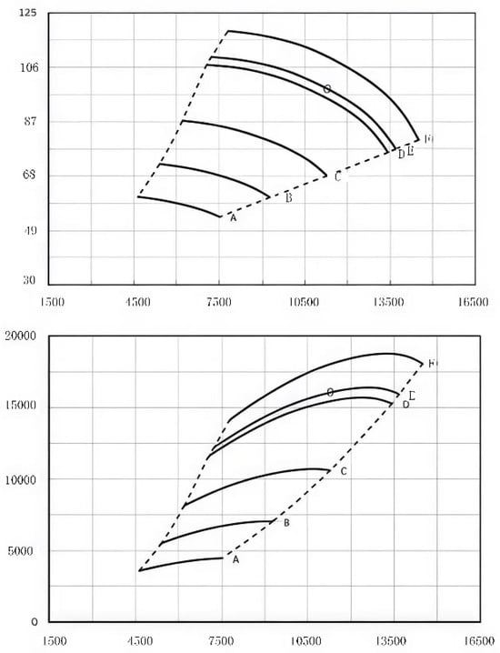
Figure 1.
Polytropic efficiency versus shaft power of the designed centrifugal compressor.
According to API 617 [18], a 4% negative allowance on compressor power and a 5% pre-overhaul derating of the gas turbine should be considered, giving a total power requirement of approximately 18,530 kW. The selected domestic gas turbine produces 19,119 kW at 36.2 °C, as illustrated in Figure 2, which satisfies the power matching requirement.
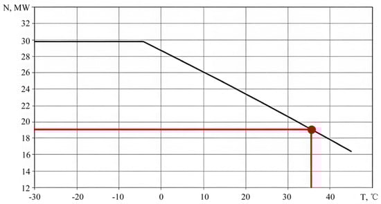
Figure 2.
Output power of the selected gas turbine at 36.2 °C ambient temperature.
2.2. Risk Identification and Analysis
Risk identification and analysis were conducted for the 25 MW gas turbine, a centrifugal compressor of equivalent capacity, and the complete gas turbine-driven compressor skid. The assessment considered the manufacturers’ design and manufacturing capabilities, performance records, and field application experience.
The 25 MW-class gas turbine is relatively mature, with application experience in both onshore and offshore projects. However, BCL808 compressors have mainly been used for hydrogen service in existing projects, and previously reported applications did not exceed a discharge pressure of 3 MPa. Domestic gas turbine manufacturers possess the ability to assemble gas turbine-driven compressor skids for onshore service, but there are significant differences between onshore and offshore applications—particularly in control system integration, skid base-frame design, and vibration isolation—which require careful consideration.
Based on this analysis, the main technical risks and key tasks for localization are: compressor aerodynamic and structural optimization (see Section 3), skid base-frame and vibration isolation design (see Section 4), control system integration (see Section 5), and package-level performance testing and verification (see Section 6).
3. Optimization Design of the Centrifugal Compressor
3.1. Compressor Selection and Structural Measures
Considering the characteristics of the offshore environment and the aerodynamic requirements—specifically the large pressure ratio and wide operating flow range—a model suitable for low-speed, high-pressure-ratio operation and capable of stable low-flow operation without recycle was selected.
To meet the speed constraints, the impeller diameter was increased and the number of impeller stages was raised; the BCL808 centrifugal compressor was ultimately chosen. Structural measures include: large-diameter impellers with shortened bearing span to improve rotor stability, an enlarged balance disk to reduce axial thrust caused by the large pressure ratio, high-precision thrust bearings with good thermal performance to withstand residual axial loads, and imported dry gas seal housings to ensure sealing reliability under pressure fluctuations.
3.2. Flow-Passage Structure Optimization
Structural optimization and flow analysis were carried out for the compressor inlet volute, discharge volute, and internal flow passages through an iterative design process. The optimization did not involve major changes to the overall structural form; instead, for the large-shaft, large-casing centrifugal compressor used in this study, the transition lengths and dimensions between the inlet/outlet volutes, inlet/outlet piping, and the compressor flow passages were refined to ensure optimal flow performance. In the revised computational setup, a tetrahedral mesh was generated for the flow domain, containing approximately 2,951,312 cells, and a grid independence test was performed to ensure the reliability of the CFD results. As shown in Figure 3 and Figure 4, these optimizations improved flow uniformity and reduced aerodynamic losses, decreasing volute loss from 1.3% to 1.1%. The compressor’s polytropic efficiency exceeded 82%, reaching the level of comparable imported units.
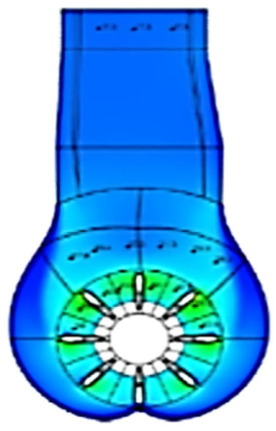
Figure 3.
Optimized structure of the compressor inlet volute.
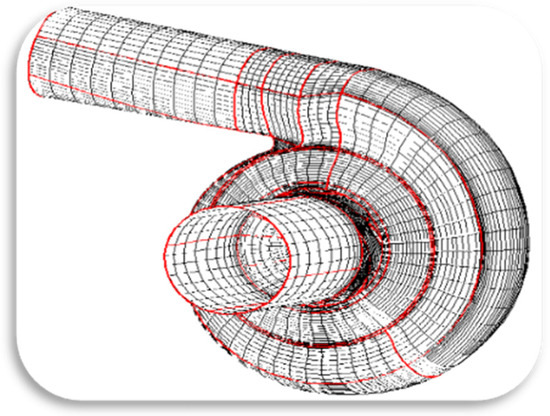
Figure 4.
Optimized structure of the compressor discharge volute.
3.3. Structural Reliability of the Compressor Body
To ensure long-term reliable operation under complex offshore conditions, the compressor casing is designed as a forged shell with two end covers. The end-cover assembly may use snap rings or bolts, and the casing is rated for a maximum discharge pressure of 20 MPa. The impellers are made of precipitation-hardening stainless steel to resist CO2 and H2S corrosion. The rotor span was shortened, stiffness increased, and bearing clearances optimized to enhance rotor stability and reduce the influence of high-pressure gas on rotor dynamics. A schematic of the compressor body is shown in Figure 5.
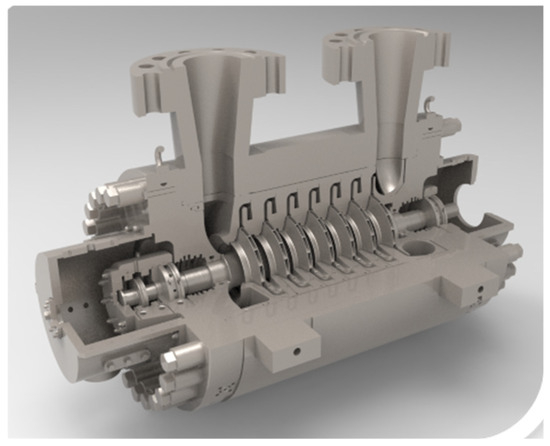
Figure 5.
Schematic of the compressor body structure.
Rotor stability is particularly critical for large-shaft, high-pressure centrifugal compressors, which are prone to dynamic instabilities such as critical speed resonance, oil-film whirl, and vibration amplification. In offshore applications, the supporting configuration—such as the three-point anti-vibration mounting (AVM)—further affects the rotor’s dynamic behavior, making stability evaluation essential to ensure safe and reliable operation. The rotor-dynamic simulations in this study were therefore performed for a special design case characterized by a large shaft diameter, a heavy barrel casing, and high-pressure operation, rather than for conventional mature models.
ANSYS 2021 R1 finite element analysis was employed to evaluate the static strength of the compressor casing and impellers. The mesh model, shown in Figure 6, was generated using tetrahedral mid-node elements, with bolt holes and minor geometric details simplified to balance computational accuracy and efficiency. Under the maximum operating pressure of 18.15 MPaG, the stresses in the main pressure-bearing components were calculated as summarized in Table 1.
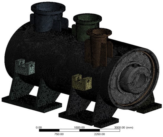
Figure 6.
Finite element mesh model of the compressor casing.

Table 1.
Stress conditions of the compressor casing.
The impeller material, FV520B-S, exhibited a maximum equivalent stress of 339 MPa at the maximum continuous speed, well below its yield strength of 686 MPa, confirming sufficient strength margins, as illustrated in Figure 7.
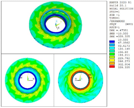
Figure 7.
Equivalent stress distribution of the impeller.
3.4. Rotor Dynamics and Stability Analysis
Rotor dynamics analysis was performed to verify critical speeds, unbalance response, and stability. The unbalance response and spectrum are shown in Figure 8 and Figure 9. The first critical speed margin is 19.1% and the second is 24.1%, both meeting API 617 requirements, indicating sufficient dynamic separation.
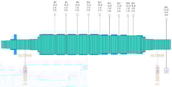
Figure 8.
Unbalance response of the rotor system.
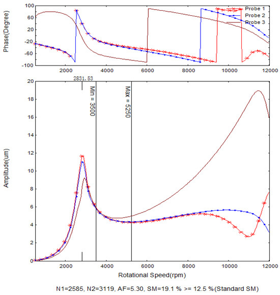
Figure 9.
Unbalance response spectrum of the rotor system.
The first-order logarithmic decrement is 0.245, and the ratio Q0/QA ranges from 2.08 to 2.78, indicating stable rotor operation, as shown in Figure 10.
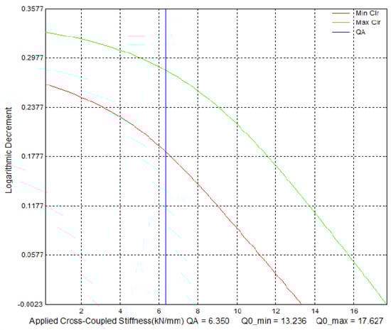
Figure 10.
Rotor stability curve (logarithmic decrement vs. cross-coupled stiffness).
4. Skid Base-Frame and Vibration Isolation Design
4.1. Vibration Isolation Design
Unlike onshore installations that typically use concrete-grouted foundations without vibration isolation, offshore steel-deck platforms require specific vibration isolation measures. With reference to foreign gas turbine-driven compressor skid designs and domestic gas turbine generator isolation practices, a three-point support vibration isolation system was adopted. A Vibratec AVM heavy pad-type isolator with offshore application records was selected. The structural steel is S355J2G3 with NORSOK M-501 A.1 surface treatment, and other steel parts are AISI 316 stainless steel. Imported wire-mesh pads are used as damping elements.
The support frame uses three support points to suppress vibration transmission to the platform structure. Elastic assemblies are installed under the base frame to form the isolation system. As shown in Figure 11, the three support points—A (under the gas turbine front support), B and C (under the compressor)—are arranged so that support A is fixed laterally and adjustable axially; support B is fixed in both directions; and support C is adjustable laterally and fixed axially. The calculated reaction forces in the X/Y/Z directions for the three supports are listed in Table 2 and can be used for platform structure verification.
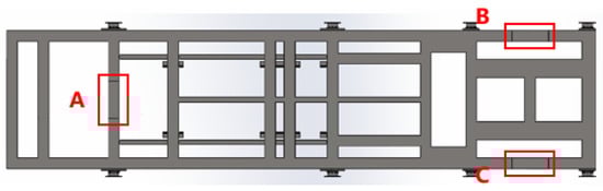
Figure 11.
Three-point support layout.
Table 2.
Reaction forces at three support points (kN).
4.2. Base Frame Optimization Design
Both integral and split base frames are used in offshore gas turbine-driven compressor and generator packages, such as GE LM2500 (integral) and Siemens SGT600/SGT700 (split). From a fabrication and transportation perspective, long integral frames are prone to welding deformation, whereas split frames are easier to transport and lift. Therefore, a split base frame was selected. The total base length is 16,090 mm, including an 11,967 mm gas turbine skid and a 4123 mm compressor skid.
Finite element analysis was performed to verify stress and deflection under static, dynamic, and lifting conditions. The results are summarized in Table 3 and Table 4, while the stress and deflection distributions are shown in Figure 12, Figure 13 and Figure 14.
Table 3.
Base frame stresses under different conditions (N/mm2).
Table 4.
Base frame deflections under different conditions (mm).
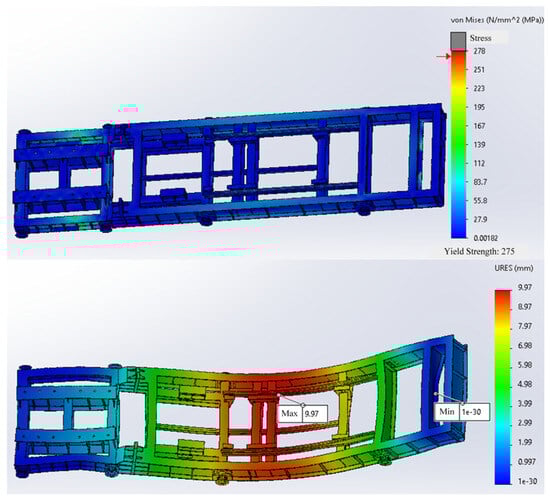
Figure 12.
Stress and deflection distribution under static load.
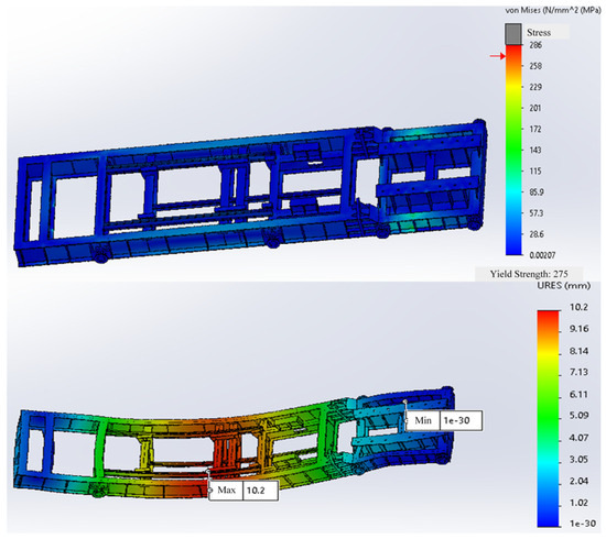
Figure 13.
Stress and deflection distribution under dynamic load.
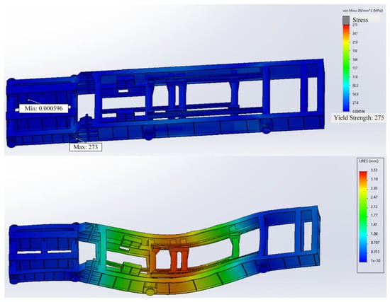
Figure 14.
Stress and deflection distribution during lifting.
The split base frames are connected using M42 bolts. Under a 2× g load, the calculated torsional moment is 2116 kNm and the shear load is 369.8 kN. The connection plate material is Q45B with a yield strength of 345 MPa. The bolt preload torque provides a resisting moment of 4165.2 kNm (>2116 kNm); the total bolt shear capacity is 1430.9 kN (>369.8 kN); and the connection plate shear stress is 0.3369 MPa (<345 MPa). These results confirm that the split base frame design meets the strength requirements.
Vibration verification was conducted on the gas turbine skid. The first six natural frequencies are listed in Table 5. The minimum natural frequency is 11.768 Hz, while the minimum rotor operating frequency is 53.333 Hz (corresponding to a speed of 3500–5000 rpm). The separation factor is 0.446, which satisfies the design requirement that the foundation natural frequency must be at least 20% away from the equipment operating frequency. Thus, resonance is avoided and the base frame has adequate stiffness.
Table 5.
Gas turbine base natural frequencies (Hz).
5. Control System Optimization Design
5.1. Control System Architecture
The control system for the gas turbine-driven centrifugal compressor package comprises three Unit Control Systems (UCS) and one Load Share Management (LSM) system. The UCSs are responsible for unit-level detection and control functions, including start/stop sequences, process control of pressures and valves, protection/emergency shutdown/fault trips, unit-status monitoring, fire detection and firefighting control, historical data logging, and alarm management. The LSM handles station-level load distribution and bypass valve control, coordinating load sharing among units and managing bypass-line valves for the compression station [20,21].
The control system is designed to achieve two main objectives. First, the compressor control system, particularly the anti-surge function, is fully integrated into the gas turbine control system at both hardware and software levels to achieve a high degree of functional unification, which is necessary for compact and reliable offshore operation. Second, considering the islanded operation characteristics of offshore units, a global process recirculation control is implemented on top of each independently controlled gas turbine-driven compressor unit to enhance overall system stability and operational flexibility under offshore conditions.
5.2. Unit Control System (UCS)
As shown in Figure 15, the UCS provides monitoring and control of the gas turbine and compressor, and also monitors/controls key process valves on the piping (inlet shut-off valve, inlet balance valve, outlet shut-off valve, outlet vent valve, anti-surge valve). Main monitored signals include inlet pressure, inlet temperature, inlet flow, outlet pressure, and outlet temperature.
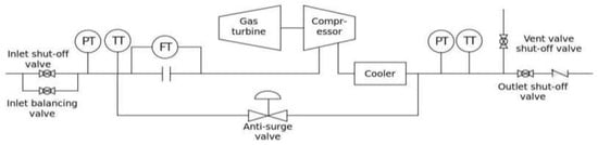
Figure 15.
Key monitored and controlled signals of the UCS.
The UCS functions include: gas turbine start/stop and warm-up control; turbine operation monitoring and protection (overspeed, overtemperature); compressor control and monitoring (surge protection, flow/pressure control, setpoint speed control); auxiliary systems control; alarm and trip handling; HMI; backup overspeed protection; bearing vibration and shaft displacement monitoring and protection; combustible-gas detection and firefighting control within the turbine enclosure; control and monitoring of compressor inlet/outlet isolation, balance and vent valves; anti-surge control; compressor inlet/outlet pressure control; flow control; setpoint speed control; and dry gas seal system control. As shown in Figure 16, the UCS contains the major functional modules for turbine and compressor control and protection.
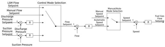
Figure 16.
Main functional modules of the UCS.
Operating modes include flow-control mode, LSM-controlled mode, inlet-pressure-control mode, outlet-pressure-control mode, automatic and manual modes. After the turbine is started and warmed up, the unit may be loaded and operated under these modes.
Hardware design, production and integration of the UCS are provided by the gas turbine OEM, covering turbine, compressor and package auxiliary hardware. The package control software is developed by the turbine OEM, while the compressor anti-surge and dry gas seal PLC programs are supplied by the compressor manufacturer (China State Shipbuilding Corporation Limited, Harbin, China). The turbine OEM integrates the control-program structure and develops the main program; the anti-surge and dry-gas-seal programs are configured as independent “tasks” with local variables to avoid conflicts with the main program. After embedding these programs into the host controller, integrated functional tests are performed.
5.3. Load Share Management (LSM) System
The LSM coordinates the operating points of the three units to maintain comparable distances from the surge/anti-surge lines. LSM functions include load distribution control, station bypass-valve control, and process control (inlet/outlet pressure and flow).
As shown in Figure 17, the load distribution is used to coordinate and maintain a consistent distance of each unit’s operating point from the surge line/anti-surge line. The booster station bypass valve control includes high outlet pressure protection, low inlet pressure protection for the booster station, and unit anti-surge protection. Process control includes inlet pressure control, outlet pressure control, and flow control.
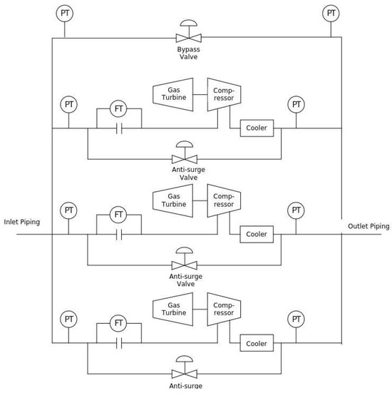
Figure 17.
Schematic of the compressor station process piping.
When three units operate in parallel, differences in compressor manufacturing tolerances, control precision, and piping result in different operating-point distances to the surge line even at the same rotor speed and anti-surge valve opening. The unit closer to the surge line is at higher risk. One LSM objective is to equalize the surge margins of all units to reduce this risk.
As illustrated in Figure 18, the LSM anti-surge control strategy maintains unit distances from the surge line by coordinating flow setpoints and bypass-valve operations. The LSM control structure (Figure 19) supports modes such as flow control, outlet-pressure control and inlet-pressure control. The bypass-valve control logic is shown in Figure 20.
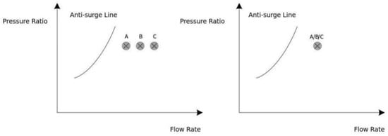
Figure 18.
LSM anti-surge control strategy.
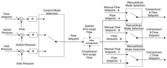
Figure 19.
LSM control structure block diagram.
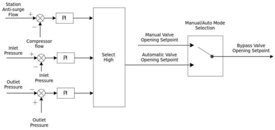
Figure 20.
Bypass-valve control structure block diagram.
6. Performance Testing and Verification
To address the risks identified previously, a targeted test strategy was developed for the compressor, gas turbine, and the integrated package.
6.1. Centrifugal Compressor Test Plan
Because the proposed BCL808 compressor had no prior operation record with natural gas at 10 MPa, a Type II performance test according to ASME PTC 10 was carried out. Test media, speeds, and conditions were selected to preserve similarity in nondimensional parameters (specific volume ratio, flow coefficient, Mach number, Reynolds number). Test conditions and design-guarantee values are summarized in Table 6.
Table 6.
Type II performance test conditions for the compressor (design vs. test).
Test-result comparisons for the Type II test are shown in Table 7.
Table 7.
Type II performance test result comparison.
The measured performance curves are plotted in Figure 21. As listed in Table 8, the measured key performance parameters are close to design values.
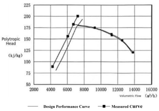
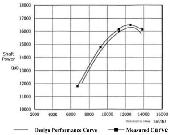
Figure 21.
Comparison of measured and design performance curves.
Table 8.
Design vs. measured compressor performance parameters.
According to API 617 and ASME PTC 10 requirements, the compressor performance meets design specifications [22].
6.2. Gas Turbine Test Plan
For the gas turbine—being a product with existing application records—standard mechanical-run and performance-test procedures per API 616 and ASME PTC 22 [23,24] were followed. Detailed procedures are consistent with those standards and are not repeated here.
6.3. Integrated Package Test Plan
For the first complete gas turbine-driven compressor package, the preferred verification approach was a full-speed full-load performance test. However, due to limitations in domestic full-package test facilities and OEM capabilities, a full-speed no-load mechanical-run combined with individual turbine and compressor performance tests was adopted to verify mechanical and hydraulic behavior.
The full-speed no-load test profile is shown in Figure 22.
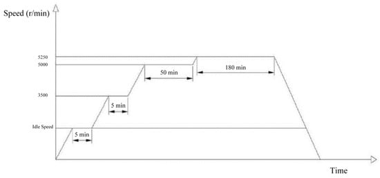
Figure 22.
Full-speed no-load test profile.
After verification, package speeds and vibration values satisfied design requirements. Representative commissioning test data and comparisons with design values are summarized in Table 9.
Table 9.
Commissioning test results for the gas turbine-driven compressor package.
7. Conclusions
The 25 MW domestically developed gas turbine-driven centrifugal compressor unit has been successfully deployed and operated on an offshore platform, demonstrating high efficiency and stable performance comparable to imported equipment. The unit has achieved significant project-level benefits, including approximately 60 million CNY in cost savings per unit and a reduction in delivery time from 24 months to less than 18 months, while breaking the monopoly of foreign units and exhibiting strong market competitiveness. The main technical conclusions are as follows:
- (1)
- Based on the performance requirements, an overall matching design of the compressor and gas turbine was completed. The compressor flow path and structural reliability were optimized to reduce vane losses and enhance rotor stability.
- (2)
- A three-point anti-vibration mounting (AVM) support system and an optimized skid base frame were designed to meet the specific structural requirements of offshore platforms. Their reliability was validated through finite element analysis.
- (3)
- To address the lack of real-time maintenance conditions during offshore operation, an integrated control system and load distribution system were implemented, enhancing operational safety and flexibility.
In summary, the design and successful application of this 25 MW domestic gas turbine-driven centrifugal compressor unit represent a major breakthrough in the localization of offshore oil and gas platform compression equipment in China. Beyond immediate project-level benefits, the offshore-specific design features—such as the three-point AVM support, supporting base frame, and specialized testing requirements—provide valuable reference for future first-time offshore applications. Furthermore, the innovation and deployment of this unit contribute to the development of related industrial chains, promoting technological autonomy and strengthening the industrial competitiveness of China’s offshore oil and gas sector. With wider application in ongoing and future offshore projects, this unit is expected to achieve broad adoption in both domestic and international markets.
Author Contributions
Methodology, F.Y., W.A., J.W. and L.Z.; Software, Z.C.; Investigation, H.X.; Writing—original draft, Z.C.; Writing—review & editing, F.Y., W.A. and L.Z.; Project administration, F.Y. All authors have read and agreed to the published version of the manuscript.
Funding
Oil&Gas Major Project (Grant No.2024ZD1403305).
Data Availability Statement
The original contributions presented in this study are included in the article. Further inquiries can be directed to the corresponding author.
Conflicts of Interest
Fengyun Yang, Zicong Cao, Weizheng An and Haibo Xu are affiliated with CNOOC Research Institute Co., Ltd. The other authors declare no conflicts of interest.
References
- Wu, K.; Qu, L. Design and Adaptability Analysis of Integrated Pressurization–Gas Lifting Multifunctional Compressor for Enhanced Shale Gas Production Flexibility. Processes 2025, 13, 1233. [Google Scholar] [CrossRef]
- Chen, H.; Li, G. The Influence of Variable Operating Conditions and Gas Composition on Multi-stage Centrifugal Compressor Performance. Energies 2025, 18, 3930. [Google Scholar] [CrossRef]
- Bicchi, M.; Marconcini, M. Multi-Point Surrogate-Based Approach for Assessing Centrifugal Compressor Stage Performance under Variable Operating Conditions. Energies 2023, 16, 1584. [Google Scholar] [CrossRef]
- Uusitalo, A.; Jaatinen-Värri, A. Centrifugal compressor design analysis for large-scale systems and cycle integration. Appl. J. Turbomach. Energy Eng. 2024, 257, 124355. [Google Scholar] [CrossRef]
- Su, Y.; Chen, X. Study of Parallel Compressor System and Real-Time Modular Dynamic System Greitzer (MDSG) Modeling. Machines 2023, 11, 213. [Google Scholar] [CrossRef]
- Peng, Q.; Bao, R. Centrifugal compressor performance prediction and the effect of hydrogen blending. Energy 2024, 52, 872–893. [Google Scholar] [CrossRef]
- Al Mamari, A.; Al Azri, N.; Al Rawahi, N. Aerothermodynamic and rotordynamic performance evaluation to diagnose deposits accumulation in a gas lift centrifugal compressor. Case Stud. Therm. Eng. 2024, 57, 104306. [Google Scholar] [CrossRef]
- Al Yahyai, M.; Mba, D. Rotor dynamic response of a centrifugal compressor due to liquid carry over: A case study. Eng. Fail. Anal. 2014, 45, 436–448. [Google Scholar] [CrossRef]
- Taher, M.; Evans, F. Centrifugal Compressor Polytropic Performance—Improved Rapid Calculation Results—Cubic Polynomial Methods. Int. J. Turbomach. Propuls. Power 2021, 6, 15. [Google Scholar] [CrossRef]
- Sutoyo, H.R.D.; Angga, I.G.A.G.; Schümann, H.; Berg, C.F. Energy efficiency of oil and gas production plant operations. Geoenergy Sci. Eng. 2023, 226, 211759. [Google Scholar] [CrossRef]
- Jiang, P.; Tian, Y. Design and analysis of centrifugal compressor for CO2 heat-pump / high-pressure applications. Sci. Rep. 2024, 14, 55698. [Google Scholar] [CrossRef]
- Hui, Y.; Wang, M. Comprehensive review of development and applications of hydrogen and related pipeline technologies in China. Sustain. Energy Rev. 2024, 315, 118776. [Google Scholar] [CrossRef]
- Wu, K.; Yang, J. A Multi-Period Model of Compressor Scheme Optimization for Flexible Gas Transport Systems. Processes 2023, 11, 3101. [Google Scholar] [CrossRef]
- Wang, Y.; Yan, J. Study of performance changes in centrifugal compressors when refrigerants/fuels are changed. Energies 2024, 17, 2784. [Google Scholar] [CrossRef]
- Gasparin, E.; Mattos, V. Parametric optimization applied to design a high-performance centrifugal stage. Int. J. Turbo Jet-Engines 2024, 46, 111–130. [Google Scholar] [CrossRef]
- Damo, T.P.; Becker, L.B.; Basso, F.P. Model-driven engineering infrastructure and tool support for petrochemical industry automation. Adv. Sci. Technol. Eng. Syst. J. 2019, 4, 174–187. [Google Scholar] [CrossRef]
- Blanco-Patiño, D.F.; Niño-Navia, J.; Garcia-Sepulveda, J.I.; Nieto-Londoño, C. Performance improvement of a centrifugal compressor under surge and choke. Eng. Rep. 2024, 24, 100935. [Google Scholar] [CrossRef]
- API Standard 617; Axial and Centrifugal Compressors and Expander-Compressors for Petroleum, Chemical and Gas Industry Services, 9th ed. American Petroleum Institute: Washington, DC, USA, 2022. Available online: https://www.apiwebstore.org/standards/617 (accessed on 28 September 2023).
- Gesser, R.S.; Sartori, R. Advanced control applied to a gas compression system of complex plants. Control Eng. Pract. 2022, 208, 109428. [Google Scholar] [CrossRef]
- Li, Z.; Kong, W. Investigation on aerodynamic performance of a centrifugal compressor with leaned and bowed 3D blades. Processes 2024, 12, 875. [Google Scholar] [CrossRef]
- Yang, C.; Fan, L. Optimization methods for large-flow coefficient centrifugal compressors. Front. Energy Res. 2024, 12, 1432725. [Google Scholar] [CrossRef]
- ASME PTC 10-1997; Performance Test Code on Compressors and Exhausters. The American Society of Mechanical Engineers: New York, NY, USA, 1997. Available online: https://www.asme.org/codes-standards/find-codes-standards/axial-and-centrifugal-compressors/2022/pdf (accessed on 28 September 2023).
- API Standard 616; Gas Turbines for the Petroleum, Chemical, and Gas Industry Services, 5th ed. American Petroleum Institute: Washington, DC, USA, 2022. Available online: https://www.apiwebstore.org/standards/616 (accessed on 28 September 2023).
- ASME PTC 22-2014; Performance Test Code on Gas Turbines. The American Society of Mechanical Engineers: New York, NY, USA, 2014. Available online: https://www.asme.org/codes-standards/find-codes-standards/gas-turbines?utm (accessed on 28 September 2023).
Disclaimer/Publisher’s Note: The statements, opinions and data contained in all publications are solely those of the individual author(s) and contributor(s) and not of MDPI and/or the editor(s). MDPI and/or the editor(s) disclaim responsibility for any injury to people or property resulting from any ideas, methods, instructions or products referred to in the content. |
© 2025 by the authors. Licensee MDPI, Basel, Switzerland. This article is an open access article distributed under the terms and conditions of the Creative Commons Attribution (CC BY) license (https://creativecommons.org/licenses/by/4.0/).