Abstract
An ambit of enhancing heat transfer throughout thermal convection in a cavity is explored numerically in this study, contemplating the heat dispersal from a segmental heat source circumscribed in a square-vented porous cavity with a moving lid. The cavity can be used as a heat sink for electronic cooling, material processing, and convective drying. Aluminum PPI metal foam saturated by aluminum oxide–water nanofluid is occupied in this lid-driven vented cavity system. The bottom cavity wall is fully and partially heated by a heat source of specific length , and the left wall and inlet fluid are kept at the same cold temperature, while the right wall and top-driven wall are thermally insulated. Thermal dispersion and local thermal non-equilibrium effects are included in an energy equation, and continuity and Darcy–Brinkmann–Forchheimer momentum equations are implemented and resolved by utilizing the finite volume method with the aid of a vorticity–stream function approach operation. The inspirations behind pertinent parameters, including the Reynolds number (), Grashof number (), inlet and outlet ports’ aspect ratio (), outlet port location ratio (), and discrete partial heating ratio () are scrutinized. The baseline circumstance corresponds to full-length heating and the outlet port location ratio . The results reveal that the fluid and heat flow domains are addressed mostly via these specification alterations. For , increasing from to does not alter streamlines or the isotherm field, but when it is detected that streamlines increase monotonically. Streamlines are not altered when and are amplified but strengthened more when the opening vent aspect ratio is increased. A greater temperature difference occurs as is raised from and isotherms are intensified, and the thermal boundary layer becomes more distinct when is augmented. The average Nusselt number rises as , , , and are increased by about , , , and , respectively, and it decreases with amplifying is increased by around .
1. Introduction
Lid-driven vented cavity thermal systems have received attention in recent years due to their widespread practical engineering and technology applications, including convective drying, material processing, solar energy power flow, nuclear reactors, and electronic cooling [1,2,3]. Porous materials can be utilized in many of these application fields to improve convection heat transfer [4,5,6,7,8,9]. Certainly, the crucial problem in frequent heating and cooling thermal applications is the low thermal conductivity of the traditional fluids employed, for instance, air, water, and oil. Accordingly, the two foremost important techniques can be used to enhance the thermal conductivity of conventional fluids, by means of nanoparticles distributed in fluids and/or filling applied areas with porous materials consistent with the type of engineering request [10,11,12].
The technique of filling cavities with pure-fluid- or nanofluid-saturated porous media to augment the rate of heat transmission has been established by many investigators and implemented in vented enclosures to achieve superior effective thermophysical properties, which results in an improved thermal operation. Non-Darcy forced and free convection in a vertical slot occupied with confined porous insulation with two wall infiltrations was explored numerically by ref. [13]. The impact of openings’ positions and infiltration velocity alteration was studied, and the authors deduced that the Nusselt number intensifies with increased infiltration velocity. Subsequently, two-dimensional steady mixed convection flow in a square vented enclosure wholly packed with fluid-saturated porous medium was scrutinized numerically by utilizing the finite-volume method by refs. [14,15,16]. They inspected the invention outcome of Rayleigh and Peclet numbers, aspect ratio, the width of the inlet as a portion of cavity height, and enclosure outlet port width and position on heat transfer characteristics for mutually opposing and aiding flow. The most important conclusion from their study is that the maximum heat transmission occurs when the outflow vent is positioned in the upper right corner, and the lowest transmission of heat is attained when the outlet port is placed in the upper left or lower right corner. They also concluded that entropy generation and average Nusselt numbers are augmented with amplifying inlet size as a portion of the cavity width ratio.
After that, numerous cases for convection heat transfer in a fluid-saturated porous square cavity with injection and/or suction inspirations were investigated numerically by refs. [17,18,19]. They studied two cases of non-Darcy and Darcy mixed convection, firstly in numerous suction effect cases and secondly under injection/suction influences with sinusoidally fluctuating temperature on a vertical side wall. The alteration in related parameters was analyzed, including Grashof and Rayleigh numbers, vent width, injection/suction velocity, and sinusoidally changing temperature profile amplitude. They inferred that the Nusselt number and temperature, and flow fields are affected by the abovementioned relevant parameters.
Furthermore, refs. [20,21] numerically inspected the addition effect of water-saturated porous media to a square heated vented enclosure in terms of flow and thermal characteristics within the porous cavity. The relevant parameters elaborated were Grashof, Richardson, Darcy, and Reynolds numbers; diameter of porous particles; metal foam porosity; and inlet width as a portion of enclosure height. Their main conclusions were that the average Nusselt number growths with the width of the inlet to the cavity height portion, and the Darcy and Reynolds numbers increase and porosity decreases when rising particle diameter, with a consequent reduction in values of Nusselt number. Also, they deduced that the variation in the Grashof number has very little impact on the average Nusselt number values. Subsequently, ref. [22] numerically examined mixed convection heat transmission in a two-dimensional square enclosure crossed by a porous medium saturated with high-concentration nanofluid under the influences of suction/injection zones. The outcome of related parameters, including Rayleigh, Darcy, and Reynolds numbers and sizes of inlet and outlet ports, on nanofluid flow and heat transfer patterns was inspected in their study. They found that heat transfer is enhanced with the increase in Rayleigh and Reynolds numbers and the sizes of the inlet/outlet sections.
Additionally, ref. [23] experimentally accomplished mixed convection heat transfer in a vented cavity with side disparately heated and packed and coarse-grained porous medium saturated with water. At a certain Prandtl number value, the Rayleigh and Reynolds numbers variation effect on thermal performance inside a cavity was examined, and they found that the Nusselt number is remarkably greater when the cavity is occupied with porous media, as associated with pure working fluid filling as Reynolds and Rayleigh numbers are enlarged. Afterward, for both opposing and adding flow, transient mixed convective heat transmission in an inclined wavy vented cavity filled with porous medium saturated by hybrid nanofluid was numerically performed by ref. [24]. His enquiry was accomplished for a wide range of Rayleigh and Peclet numbers, amplitude of wavy wall, and enclosure inclination angle, and gathered that the mixed convection, in addition to the Nusselt number, is amplified as the amplitude of wavy wall and nanoparticles volume portion grow. As well, it has been concluded that the Nusselt number in aiding flow case is more efficient than the case of opposite flow. Furthermore, convection heat transmission mode and thermal physical characteristics in a square enclosure with inlet and exit opening vents crossed by saturated non-Darcian porous material were numerically accomplished by refs. [25,26,27]. The pertinent parameters performed in their work are the nanoparticles volume fraction, heating source length, and Reynolds, Grashof, Richardson, Darcy, Hartmann, and Prandtl numbers, along with solid/fluid thermal conductivity fraction, porosity, angle of magnetic field, and inflow/outflow vents width fraction. Chiefly, they deduced that the attendance of porous media improves thermal performance and also observed that thermal spreading within the cavity, comprising Nusselt number, enhances with nanoparticles concentration, the length of heating source, Grashof and Darcy numbers, and porosity reduction. Moreover, ref. [28] numerically contemplated the dilemma of mixed convection in a cavity with outlet and inlet opening ports underneath the action of a cyclic magnetic field, and crossed by oxytactic bacteria nanofluid saturated porous medium. They anticipated the disparity consequences of pertinent parameters, Richardson, Lewis, and Peclet numbers, and achieved that at least of heat transmission growth occurs among the lowermost and uppermost values of Peclet numbers.
Recently, studies of square enclosures crossed by saturated porous media with a moving wall were widely investigated and published. Numerous of these studies are devoted to moving lid enclosures filled with porous media saturated with pure fluid. The problem of convection heat transfer in cavities filled with pure fluid saturated porous media of a constant velocity driven upper wall, subjected to various types of thermal boundary conditions, was examined by many authors like references [29,30,31,32,33,34,35,36,37,38,39]. In general, they investigated the influence of relevant parameters, including Prandtl, Darcy, Reynolds, Richardson, and Grashof numbers, porosity, and heating length. They deduced different conclusions according to the boundary conditions stated for each problem and the parameter range.
Conversely, heat transfer by convection in driven upper wall cavities filled with porous media and saturated with nanofluid was also inspected. The heat transfer by mixed convection in a square lid-driven porous cavity saturated by copper-water nanofluid with various lengths and different locations of the heat source was numerically performed by ref. [40]. Variation effect of Richardson and Darcy numbers, porosity, and solid volume fraction was involved in their work, and they concluded that the overall heat transfer rate enhances when the heat source is located at the top of the hot wall and its length is one-third of the total length. And rate of heat transferred grows as the Darcy number and nanoparticle volume fraction are augmented. Moreover, ref. [41] numerically scrutinized mixed convection and entropy generation in a square moving lid alumina-water nanofluid porous cavity regarding the influences of internal heat generation. The outcomes of varying Richardson, Darcy, and Lewis numbers, porosity, buoyancy ratio, nanoparticles volume fraction, heat generation/absorption, and chemical reaction parameters in certain ranges were thoroughly observed. They concluded that average Nusselt and Bejan numbers are increased as Richardson and Darcy numbers, and porosity are raised. Afterward, the mixed convection in a moving lid porous cavity saturated with copper-water nanofluid in the presence of a magnetic field effect was numerically proposed by refs. [42,43]. Pertinent wide range parameters involved in their scrutinize were Richardson, Darcy, and Hartmann numbers, phase deviation, amplitude ratio, thermal radiation, and solid nanoparticle volume fraction. The main deduction of their work, the average Nusselt number and heat transfer rate are raised as the concentration of nanoparticles and amplitude ratio are increased, and they are reduced with the increase in either Hartmann number or Richardson number when thermal radiation exists. Meanwhile, magneto-convection flow in a corrugated lid-driven porous enclosure saturated with nanofluid and subjected to a magnetic field was numerically accomplished by refs. [44,45]. They observed the outcomes of varying relevant parameters, namely Reynolds, Darcy, and Hartmann numbers and the number of wall corrugations, and concluded that flow field, heat transfer rate, and irreversibility are related directly to these parameters.
Very rare inquisitions were found for lid-driven vented enclosure thermal systems, although of their importance in enhancing heat transfer. These inquiries were surveyed regardless of the media used in the enclosure or boundary conditions. The problem of mixed convection in a moving lid vented cavity with a left side flexible wall was numerically handled by ref. [46]. The heat source was set partially on the bottom cavity wall, and its top wall had three different moving cases. They performed variations influence of Richardson number and the velocity ratio of the moving top wall to that of air entering the cavity. Their results revealed that the Nusselt number increases with the Richardson number rising. Additionally, ref. [1] numerically scrutinized convective heat transfer and phase transition in a moving wall trapezoidal vented enclosure furnished with condensed phase change materials under a non-uniform magnetic field by employing ternary nanofluid. The outcome of changing Reynolds and Hartmann numbers, wall velocity, upper wall inclination, non-uniform amplitude, and nanoparticle volume fraction was assessed in their work. They deduced that increasing the Reynolds number, the upper wall inclination angle, and nanoparticles in the base fluid augments thermal performance and reduces the transition time of phase change. Furthermore, heat dissipation from a discrete heat source confined in a vented enclosure with an upper driven lid and flexible left wall was numerically established by ref. [47]. They meditated the heat transmission process for a wide range of executed parameters, Prandtl, Richardson, and Reynolds numbers, flexible wall elasticity, and location of inlet vents. As a result of their work, lowering the inlet port position, decreasing the Prandtl number, and increasing the Reynolds number result in a higher Nusselt number and improve overall performance.
It can be deduced from the pertinent above-mentioned literature survey, and according to the author’s knowledge, there is a shortage in research that deals with lid-driven–vented cavity systems filled with nanofluid saturated porous media in spite of the wide application area for this system. Practical engineering and technological applications include convective drying, nuclear reactors, material processing, solar energy systems, and electronic cooling can be progressed by using many contributions to this system of the lid-driven vented cavity. For instance, in a solar energy air-heating system, solar chimneys and photovoltaic panel cooling systems can serve as lid-driven vented cavities. One of the cavity walls can be accelerated and moved with constant velocity in order to initiate forced convection, while inlet and outlet openings represent a vent model used for air circulation. In these applications, an aluminum metal foam layer can be employed to improve heat transfer between the wall of a solar-heated enclosure and active fluid that is utilized for the house space heating system. So, heat transmission improvement is reserved as a consequence of the intensifying heat transmission exterior area that results from via metal foam along with the upgraded active nanofluid thermophysical properties.
Furthermore, it can be deduced that the heat transmission augmentation in the lid-driven vented cavity system has been the subject of several investigations, but the current literature survey has raised subsequent questions. Does the insertion of aluminum metal foam and utilizing nanofluid as the working fluid affect the heat and fluid flow inside a vented enclosure? Do the inflow and outflow openings dimension and outlet vent location, in addition to the discrete heating length, affect the energy transport improvement? There are no distinct responses in the open literature to these questions. Therefore, the contemporary paper arose to seal this gap by coupling the nanofluid saturated metal foam insertion with the discrete heated lid-driven-vented-cavity within the convective heat transfer, which is the shiny novelty of this paper. Additionally, to the extent of the author’s knowledge, the attendance of a metal foam layer saturated with oxide alumina water-based nanofluid occupied within a lid-driven vented cavity system has not been performed previously in the literature. Furthermore, a similar approach can be executed with extra applications like electronic cooling, convective drying, and additional thermal management schemes.
Accordingly, the basic goal of this paper is to investigate the convection heat transfer inside this type of enclosure resulting from the combined effects of both driving the cavity lid and the role of fluid entering through opening vents with prescribed velocity for charging and discharging cooling fluid. Moreover, the lid-driven vented cavity is filled with aluminum metal foam and saturated with aluminum oxide–water-based nanofluid to enhance heat transfer inside the enclosure, and this is a novelty point which has never been considered yet in the literature. Additionally, both effects of local thermal non-equilibrium and thermal dispersion in metal foam governing equations are taken into account. The inlet opening port is situated at the bottom-left corner, while outlet venting is positioned at different positions on opposite vertical walls, which has not been accomplished previously in the literature. Furthermore, as heating conditions are mainly pertinent in thermal systems, a heating source of various lengths is located on the enclosure’s bottom wall. The chief applicable parameters investigated in the current work are Reynolds and Grashof numbers, inlet and outlet vent sizes, exit port venting location, and length of heating source. Subsequently, the consequences are helpful for thermal enterprises affiliated with electronic cooling, convective drying, recovery systems of waste heat, etc., and observing the optimal parameters to improve thermal performance in such applications.
2. Computational Method
2.1. Problem Statement and Boundary Conditions
The physical model of the current study on the convection heat transfer in a lid-driven vented cavity of equal height and length , is portrayed in Figure 1. Lower enclosure wall is heated either totally or partially by a discrete heater of length with constant hot temperature condition whereas the left vertical side is kept at cold isothermal temperature, and the two remaining walls are insulated perfectly. The top adiabatic cavity wall is considered the lid-driven wall moving towards the right with a constant velocity of . This vented enclosure is occupied with an aluminum metal foam layer of a specific pores per inch PPI value. The metal foam is saturated with an aluminum oxide–water nanofluid of volume of solid nanoparticles fraction. This nanoparticle volume fraction value was chosen since it denotes an extensively stated concentration to produce noteworthy enhancements in thermal conductivity and heat transmission performance [48,49,50,51,52,53]. Inflow cold working fluid () venting is situated on the left lower enclosure corner, and outlet venting is positioned at four different distances from the lower right corner. The inlet vent dimension is similar to that of the outlet vent. There are three mechanisms that control the heat and flow field inside the lid-driven vented cavity; the fluid entering the vented cavity is responsible for ascending forced convection, temperature inconsistency between bottom discrete heating and through-stream constant velocity close to it at enclosure inlet induces buoyancy effects, as well as the shear force created by moving the top wall.
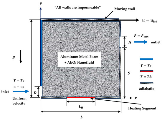
Figure 1.
Physical domain for lid-driven vented cavity system.
2.2. Mathematical Formulation and Assumptions
For the metal foam crossed in the lid-driven vented cavity of the current study, appropriate and substantial assumptions are made in observance. These hypotheses are two-dimensional, steady state, incompressible, laminar flow, enclosure boundaries are impermeable, radiative heat transmission, and viscous energy dissipation influences are assumed to be irrelevant. It is noteworthy to mention that two-dimensional and laminar assumptions may not take into consideration three-dimensional instabilities or transmission to turbulence that happen in applied enclosure heat and fluid flows at higher Reynolds numbers. Also, neglecting radiation heat transfer may decrease accuracy in high-temperature requests where radiative heat transmission acts as an important function. In addition, it is postulated that metal foam is hydrodynamically and thermally isotropic, homogeneous, and saturated with single-phase nanofluid, which is in local thermal non-equilibrium with the metal foam solid matrix. This nanofluid single-phase model postulates uniform nanoparticle dispersion and disregards conceivable particle relocation, agglomeration, and slip-up among phases, and these consequences may affect heat transmission in practical nanofluid arrangements. The thermo-physical properties of nanofluid and porous media are constant, excluding density dependency in the buoyancy term of the momentum equation, which is fulfilled by the approximation of Boussinesq. Moreover, it is idealized that solid aluminum nanoparticles and water as a base fluid are in thermic equilibrium, and any slip velocity exists among them. The Forchheimer–Brinkman-extended Darcy pattern is utilized for modeling momentum transport in porous media. Rendering entirely to the abovementioned assumptions, governing equations for mass, momentum, and energy, including thermal dispersion and local thermal non-equilibrium effects, can be expressed as follows [2,44,50]:
Continuity Equation
Momentum Equations
where is porosity, is pressure, is foam permeability, and is the Forchheimer coefficient that can be calculated from [50].
Energy Equations
where is the temperature of the fluid phase and is the temperature of the solid phase.
Effective nanofluid and solid matrix thermal conductivity, and respectively, can be estimated from [54]:
The subsequent dimensionless parameters and numbers are introduced to redevelop governing equations in dimensionless structure so as to universalize the work and diminish the investigation parameters: , , , , , , , , , , , , , .
Therefore, Equations (1)–(5) can be expressed as below:
Continuity Equation
Momentum Equations
Energy Equations
Moreover, thermal dispersion and volumetric heat transfer of aluminum metal foam can be determined by utilizing the empirical equations modified by ref. [54]:
The thermophysical characteristics that propose operating nanofluid effective thermophysical properties as a function of nanoparticles intensification volume fraction are density , dynamic viscosity , coefficient of thermal expansion , capacitance of heat , and thermal conductivity . The next equations can be employed to attain these thermophysical properties [7,48,49]:
The thermo-physical properties of water, aluminum oxide nanoparticles [48,49] are recorded in Table 1 and deliberated to be unchanging excluding the density that varies rendering to the approximation of Boussinesq.

Table 1.
Thermo-physical properties of water-based fluid and aluminum oxide nanoparticles.
Pressure variable terms presented in dimensionless momentum formulations of the metal foam layer is eradicated by employing the description of vorticity and velocities in expressions of the stream function as, , , and . Then, the traditional operation of the stream-vorticity function procedure is executed, and consequently, the governing equations utilized in the current work formed for metal foam and nanofluid then develop into:
Continuity Equation
Momentum Equations
Energy Equations
Boundary conditions of the current work in dimensionless form can be cast as [1,16,46,47]:
Inlet port (inlet cold nanofluid uniform velocity and temperature): , , on ,
Left cold wall (no slip condition and constant cold prescribed wall temperature): , , on ,
Bottom adiabatic wall (no slip condition and adiabatic wall): , , on ,
Bottom hot wall (no slip condition and constant hot prescribed wall temperature): , , on ,
Bottom adiabatic wall (no slip condition and adiabatic wall): , , on ,
Right adiabatic wall (no slip condition and adiabatic wall): , , on ,
Outlet port (zero velocity and temperature gradient condition): , on ,
Right adiabatic wall (no slip condition and adiabatic wall): , , on ,
Top adiabatic wall (moving lid and adiabatic wall):
As a result of considering the local thermal non-equilibrium model in casting energy equations, two temperature gradients were attained inside the enclosure; specifically, temperature distribution for the solid and fluid phases. Consequently, to evaluate the heat transfer rate from the bottom discrete heating to the metal foam, there are two different Nusselt number values assessed for each phase. Also, note as has been aforementioned that the discrete heating length located at the center of the bottom cavity wall is either extending partially or along the total bottom wall . Hence, the local Nusselt number of fluid and solid phases, correspondingly, are expressed as [33]:
While the average Nusselt number of the nanofluid and solid phase which are obtained by integrating the local value along the heater length, respectively, can be stated as [33]
Furthermore, the total average Nusselt number on the discrete or total heating length can be taken as the addition of and , [33]:
In the contemporary work, the aluminum metal foam of pores per inch and porosity was selected. The physical characteristics of aluminum metal foam required during simulation are presented by ref. [54].
3. Grid Independence and Code Validation
The dimensionless equations for the continuity and momentum equation in terms of stream function and vorticity, and fluid and solid energy Equations (20)–(23) laterally with the compliant boundary condition Equation (24), were resolved by numerically implementing the finite volume method to acquire the isotherm field, stream function, and Nusselt numbers within the cavity. The governing equations’ spatial derivatives are approached by a central difference scheme [55]. The finite volume scheme abates continuum complication to a discrete problem decreed by an algebraic equations arrangement presented as a tri-diagonal matrix, which was resolved by a line-by-line technique of a tri-diagonal matrix algorithm (TDMA) [55]. For the condition of convergence, the summation of the variable (, , , ) residua were smaller than between consecutive iterations. That is, where is the specific iteration step and variable represents stream function, vorticity, and fluid-phase and solid-phase temperatures. Lastly, procedures constructed using Simpson’s rule were retained to accomplish the average Nusselt number numerical integration. Additionally, in-house computer code was acquired for the stated discretized equations and employed for the sake of calculating streamlines and isotherms, and subsequently determining the Nusselt number along the discrete heating wall. For more clarification, the flow chart exemplified in Figure 2 summarizes the commonsense and reliable sequence of numerical steps for solving governing equations in the constructed in-home computer code.
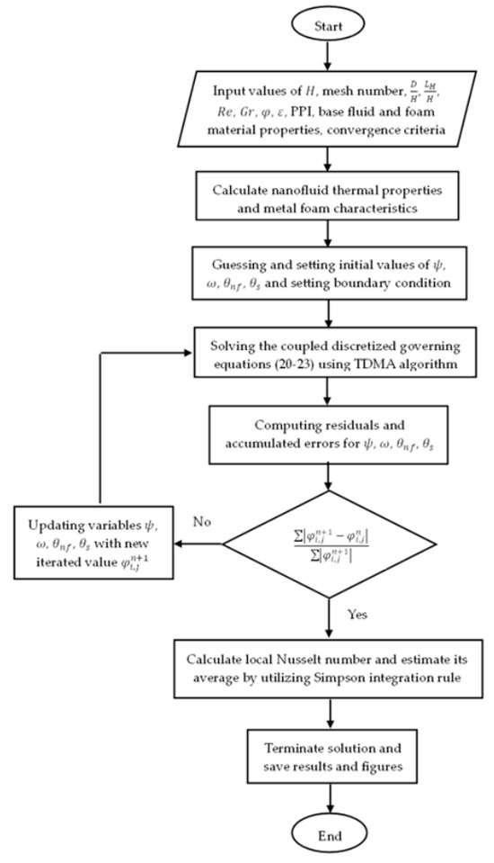
Figure 2.
Schematic flow chart of the present numerical solution of in-home computer code.
For the purpose of evaluating numerical results’ dependence on the domain spatial discretization and additionally to regulate computation time with flow and temperate accuracy, a comprehensive grid independent test was performed. Disparate-sized meshes were utilized to calculate the average Nusselt number on the bottom wall discrete heating part for the fluid and solid phase of aluminum metal foam, as revealed in Table 2. The test of grid refinement was assayed for certain values of geometrical relevant parameters , , and with three sets of heating and flow related parameters; firstly and , secondly and , and thirdly and . The results exposed that the nanofluid, solid phase, and total average Nusselt number had a very slight mutation, for a network of nodes, associated with a network of nodes and overhead. Subsequently, a node number of , whose structured grid mesh is exposed in Figure 3, was convincedly implemented for the whole simulations in the present study, since this element number met the necessities of reciprocating the study of node independence, good precision, and computational time constraints.
Table 2.
Grid refinement test, and on bottom bottom-heated wall employing frequent mesh sizes.
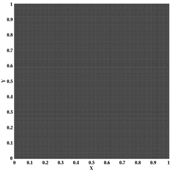
Figure 3.
Structured grid mesh for nodes number of .
Accurateness of the current evolved home-built computer MATLAB R2015b code has been inclusively authenticated by comparation its outcomes with the outcomes of ref. [16] for mixed convection heat transfer in a square porous enclosure with opening ports. This authentication, which is exemplified in Figure 4, compared the present code numerical outcomes with their streamlines and isotherm field for the circumstance of , and . Furthermore, the average Nusselt number for this case on the left heated wall was calculated by employing the current code and found as which is very near to the value proposed by ref. [16] as and relative error is achieved, which establishes excellent agreement. This consistency approves that governing equations for porous media, numerical simulation scheme, and inlet and outlet boundary conditions utilized in the contemporary study are suitable and reliable. Consequently, this contrast affords a strong validation of the present procedure and gives dependence to the consequent investigation.
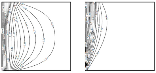
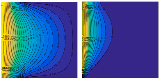
Figure 4.
Streamlines (left) and isotherm lines (right), validation (upper row) and present work (lower row), at , , and .
Moreover, an additional authentication with the numerical results of ref. [33] for the lid-driven cavity occupied by saturated metal foam was demonstrated. Stream and isotherm fields for the case of , , and are illustrated in Figure 5. In addition, the average Nusselt number on the bottom-heated wall was determined by using the present in-home code and obtained as that is very close to the value represented by ref. [33] as and relative error is attained. This constancy supports that the governing equations for metal foam, numerical solution scheme, thermal dispersion model, and lid-driven boundary condition employed in the current work are appropriate and consistent. Subsequently, this contrast affords a strong validation of the contemporary technique and provides a dependency on the consequential inquiry. These two references were considered for validation because they deal with two main points: the vented porous cavity model and the lid-driven cavity crossed by metal foam with the effect of the thermal dispersion model. From mutual validations, it is obvious that the current in-home code can emulate issued numerical results with a high grade of accurateness. Additionally, this corroboration provides a good indication of the capability of existing code to scrutinize anticipated investigation because of the admirable qualitative and quantitative agreement between results.
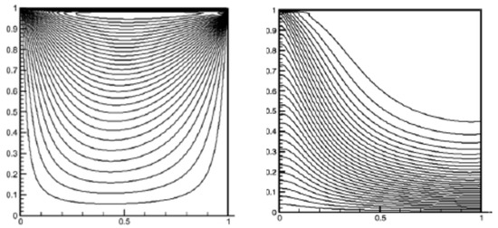
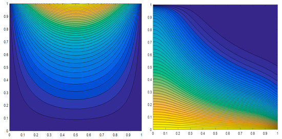
Figure 5.
Streamlines (left) and isotherms (right), validation (upper row) and current study (lower row), at , , .
In addition, according to the best of the author’s knowledge, it should be mentioned that there is no direct experimental work corresponding specifically to the exact configuration of present problem conformations and boundary conditions currently accessible in the literature.
Subsequently, experimental validation for typical current problem conformation cannot be accomplished in the current study; therefore, the experimental validation remains a limitation. And this should be preserved in the upcoming study through devoted experimental studies, which will rely on the numerical results described here to supply direct validation and additional assert the predictive ability of the numerical model.
4. Results and Discussions
The main objective of the present study is to assess the effects of insinuations of changing outlet port location and partial heating dimensions on thermal performance in a lid-driven vented enclosure filled with aluminum metal foam of . Additionally, this analysis takes into account the thermal dispersion and local thermal non-equilibrium influences. Metal foam is saturated with solid nanoparticles, aluminum oxide water water-based nanofluid of volume fraction . The presented numerical results include streamlines, isotherms, and Nusselt numbers. A wide range of pertinent parameters affecting the fluid flow and heat transfer was considered in this work comprises the Reynolds number (), Grashof number (), aspect proportions of inflow and outflow ports size to height (), outflow aperture port position ratio (), and discrete partial heating length ratio (). Selecting these ranges of Reynolds and Grashof numbers was to confirm laminar and numerically stable flow circumstances by representing low velocity flows and reasonable buoyancy-driven convection. An extensive study of the current investigation into higher flow regimes is consequently a significant path for forthcoming research.
4.1. Effect of Inlet and Outlet Vents Aspect Ratio, Grashof Number, and Reynolds Number
The influence of the inlet and outlet vents aspect ratio () on heat and flow pattern has been analyzed by depicting contours of streamlines and fluid and solid phase isotherms as illustrated in Figure 6 for the case of , , , and . In this section the ratios of and are taken as dependent values to study the effect of , , and because same physical behavior is obtained for remaining studied values. It is clearly shown from this figure that increasing vents aspect ratio tends to a superior intense in streamline values which implies higher forced convection currents and instigates considerable distinctions in the flow and temperature fields. However, temperature values in regions near hot wall does not alter significantly because the increasing amount of cold entering fluid and convection currents initiated near hot wall are not enough to introduce a high temperature gradient inside this region. Also, it can be noticed that the thermal boundary layer near bottom hot wall is almost straight lines for which means that currents of convection are feeble and conduction transmission mode is foremost in this area. On the other hand, for upper regions far from hot surface it can be shown that there is significant change in streamlines and temperature values when opening ports aspect ratio is increased, also isotherm lines seem to be more curved and thermal boundary layer becomes distinct which specifies strong currents of convection there. The main reason of this behavior is due to the larger quantity of cold fluid in addition to magnificent passageways in metal foam of those fallouts in a greater temperature gradient which is the foremost source of convection currents. That denotes selection of inflow and outflow vents sizes can be nominated rendering to the anticipated appliances for this sort of enclosures. For heating alike drying, solar power heating, etc., lesser vents sizes can be utilized although for cooling such as electronic cooling larger sizes are implemented. Additionally, from Figure 6 it is obviously revealed that no substantial alteration occurs among solid and fluid phase temperatures.
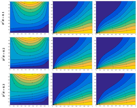
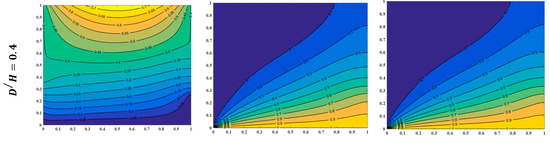
Figure 6.
Streamline (left), fluid isotherm lines (mid), and solid isotherm lines (right) for dissimilar values of inflow to outflow aspect proportion at , , , and .
The impacts of Grashof and Reynolds numbers on fluid flow and heat transfer fields have been represented for , , and , as exemplified in Figure 7 by rendering the streamlines and isotherms. For a specific value of the Grashof number , increasing the Reynolds number from to does not change the streamline field either quantitatively or qualitatively, but when the Reynolds number is taken as it can be observed that streamline values increase monotonically. This behavior can be attributed to the value of the inertia force with respect to the gravity force value because each force acts in the opposite direction. Inertia force is directed in the same direction as the inlet port velocity (positive y direction), while the gravity force direction is toward the negative y direction. Therefore, when the Reynolds number value is adopted as and lower, fluid inertia and velocity values are small, and they cannot affect the stream field, while increasing the Reynolds number to augments inertia and velocity values to intensify streamlines quantitatively and qualitatively. This is also clearly obvious in isotherm lines, increasing the Reynolds number to results in wider regions of low temperature values in the top cavity region because the inertia force is higher, which results in forced convection currents being amplified there.
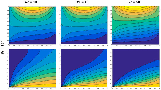
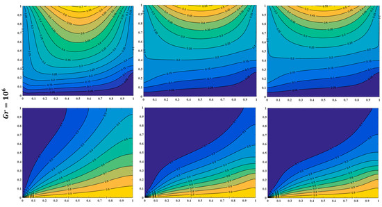
Figure 7.
Streamlines (upper) and isotherms (lower) for different values of Reynolds number and Grashof number at , , and .
Whereas, when the Reynolds number is and below, buoyancy forces are higher than inertia which fallouts in higher natural convection currents compared to forced convection, and higher temperature values take place inside the cavity, including the top region. Furthermore, increasing the Grashof number to specifies opposite behavior for fluid and heat transfer fields; described previously for . Streamlines of lower Reynolds number values are more intensified compared to those of Reynolds number equal and because the stream function values are directly proportional to the temperature that results from a higher Grashof number. At a Reynolds number of , fluid velocity and inertia force are small compared to other Reynolds number values and thus generated convection currents cannot decrease fluid temperature values significantly, which results in higher streamline values according to Equation (21).
Moreover, it is apparent from Figure 7 that there is a temperature reduction as the Reynolds number is amplified and regions with low temperature are enlarged, but less than regions when . For , the isotherms are steered nearly by natural convection because forced convection currents are comparatively weak and henceforth a greater area is dominated by higher temperature, that induces it appropriate for space heating requests. When and , forced convection currents become stronger and a distinct reduction in temperature value at the confident position inside the cavity is associated with the case of . This temperature decrease makes and more proper for the cooling requirements. In addition, from Figure 6 and Figure 7, it can be noticed that the streamline near the upper moving wall exhibits a larger value of stream function because of the larger velocity of this wall. This greater stream function value supplements a driving inertia force in addition to the inertia force resulting from the entering fluid velocity. The accumulation of these two forces enhances thermal performance inside the lid-driven vented cavities, which gives these enclosures wide utilization in engineering applications.
The behavior of solid and fluid Nusselt numbers under the influences of Reynolds and Grashof numbers and the inlet to outlet vent aspect fraction at and are portrayed in Figure 8. It is clearly perceived from this figure that a mutually fluid and solid Nusselt number rises monotony as the Reynolds number, Grashof number, and opening aspect proportion are augmented. Amplifying the Reynolds number from to at a specific value of Grashof number and ports aspect ratio tends to a growth of in the fluid-phase Nusselt number and in the solid-phase Nusselt number. This Nusselt number rise is attributed to the elevated fluid velocity that results from high Reynolds number values, which produces superior forced convection currents and thus a domination of convective heat transmission mode nearby the bottom cavity wall arises. Moreover, shear forces generated from the moving upper wall and natural buoyancy forces accompanied by the same forced convection currents direction, supplemented by increasing Reynolds number, tend to a rise in convection heat transfer mode with respect to conduction mode near the heated bottom wall and consequently the Nusselt number increases. In addition, the levitation inflow to outflow ports aspect fraction from to at exact values of and fallouts in the growth of in the fluid-phase Nusselt number and in the solid phase. The motivation for this magnification is outstanding due to a larger fluid amount entering the enclosure, which induces a higher difference in temperature among the hot wall and fluid overtaking through the aluminum foam, along with the velocity of the fluid. This fluid velocity and amount are enlarged with currents arising from the cavity moving lid and buoyancy convection currents produce a growth in stronger convection heat transmission currents compared to conduction mode and thus intensifies boundary layer thickness in this region, which results in the Nusselt number rising. Furthermore, the fluid-phase and solid-phase Nusselt numbers increase by and , respectively, as the Grashof number grows from to when and . This small percentage rise is ascribable to the rise in buoyancy forces and then increasing in natural convection currents in the same direction as convection currents resulting from moving wall shear flow and the inertia force of incoming opening fluid which impedes convection heat transfer mode relative to conduction mode in spite of its slight rise value. It is clearly shown in Figure 8 that fluid-phase and solid-phase Nusselt numbers have the same behavior for relevant parameters variation; therefore, the average Nusselt number (according to Equation (29)), which is the sum of the two phases’ average Nusselt numbers, is considered and responsible for the remaining figures in this study.
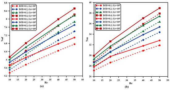
Figure 8.
Fluid and solid Nusselt number alterations with Reynolds number for numerous values of inflow to outflow aspect fraction and Grashof number at and , (a) fluid phase Nusselt number, (b) solid phase Nusselt number.
Consequently, the variation in average Nusselt number on the bottom heated wall with Reynolds number for different Grashof numbers and inlet to outlet vents aspect proportion at and is exposed in Figure 9. The same qualitative behavior of average Nusselt number with Reynolds and Grashof numbers and inlet and outlet ports aspect proportion variations is attained. Definitely, the Nusselt number increases by when the Reynolds number changes from to at and , when the inflow to outflow ports aspect fraction alerts from to at and , and as the Grashof number grows from to at and . So, quantitatively, the increase in the average Nusselt number as a sum of solid and fluid phase Nusselt numbers is almost similar to the increase in each phase individually, and also, according to this convergence, the average Nusselt number as a sum of fluid- and solid-phase Nusselt numbers can be responsible for consequent figures. Additionally, it can be obviously noticed from Figure 9a that the Nusselt number values do not alter with the increase in the Grashof number from to . This is because of the insufficient amplification in buoyancy forces, which is essentially responsible for the natural convection currents to increase the Nusselt number evidently. On the other hand, raising the Grashof number from to enhances the Nusselt number as illustrated clearly in Figure 9b, which means that buoyancy forces are enlarged enough to develop higher natural convection currents in addition to the co-direction forced convection currents supplied by the inertia force that arises from the fluid velocity (Reynolds number) presence and lid-driven shear flow in the lower part of the cavity. All these convection currents tend to thicken and intensify the thermal boundary layer near the hot bottom wall and consequently dominate the convection mode against the conduction heat transfer mode, which leads to a rise in Nusselt number. Subsequently, for cooling applications like electronic cooling, large Grashof number values are required and accompanied by a high Reynolds number and opening aspect proportion to achieve the required operating temperature in such cooling systems.
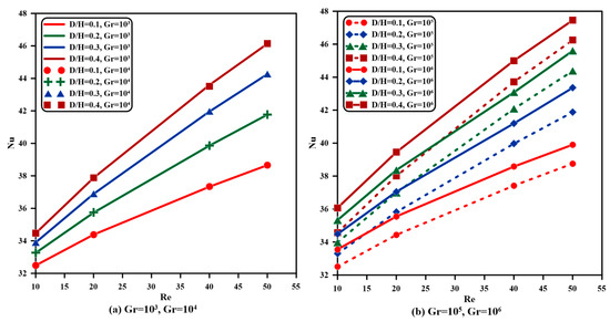
Figure 9.
Nusselt number alterations with Reynolds number for numerous values of inflow to outflow aspect proportion and Grashof number at and , (a) and , (b) and .
4.2. Effect of Partial Heating Length
Partial heating has numerous applications in engineering and technology, including electronic device cooling, nuclear waste management, chemical reactors, etc. Therefore, the present study is devoted to investigating the effect of partial heating on fluid flow and heat transfer fields in addition to the average Nusselt number change. This investigation provides a good way to select the suitable heating length according to the desired application.
The effect of partial heating length on the fluid flow and heat transfer distribution, and thermal performance is inspected and demonstrated in Figure 10 for the case of Reynolds number , Grashof number , and outlet vent location ratio . In this figure, three values of heating length to cavity length ratios (, , and ) and two values of inlet-outlet vents aspect ratios ( and ) are performed. It is noticeable from this figure and Figure 6 that changing the heating length ratio does not change the streamline field significantly for the two values of and especially when is amplified from to and from to . The reason behind this behavior is that the temperature difference during partial heating increase is insufficient to increase fluid velocity by ascending higher inertia force. While increasing from to leads to an adequate augmentation of temperature for initiating a higher inertia force and thus growing in fluid velocity. Moreover, examining isotherms in Figure 6 and Figure 10 for port aspect ratios ( and ) indicates a slight difference in temperature distribution inside the enclosure when is augmented from to , whereas other values of specify a greater temperature difference. These results can be employed to select a suitable value of the heating length to cavity length ratio according to the practical engineering application.
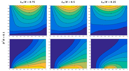
Figure 10.
Streamlines (upper) and isotherms (lower) for different values of and at , , and .
To illuminate the outcome of partial heating length ratio on average Nusselt number for dissimilar values of Reynolds number and inflow to outflow ports aspect proportion at , and and . Figure 11 is exemplified. In spite of the aforementioned little change in temperature distribution when is augmented from to , however average Nusselt number on the hot bottom wall is increased considerably. On the other hand, it is clearly shown that raising from to average Nusselt number intensifies with a smaller proportion, while raising from to Nusselt number increases with a higher percentage than from to . For instance, when , , and , the Nusselt number increases by , , and , while as , , and , the Nusselt number increases by , , and once is amplified from to , to , and to , respectively. This accruing in Nusselt number is ascribed to the cumulative temperature gradient near the hot wall because of the heater length increasing, which results in a higher heat energy entering the enclosure. This larger energy amount increases natural convection currents that ascend from the buoyancy thermal forces in the cavity, as well as the same direction shear and inertia flow convection currents which arise from moving the upper cavity wall, and the entering fluid velocity results in the Nusselt number intensifying. The fluctuation in increasing percentage, precisely when is amplified from to , is owed to certain heat energy entering the cavity not adequately enough to increase the temperature gradient and natural and forced convection currents as the augmentation in this gradient when is raised in other cases of increasing.
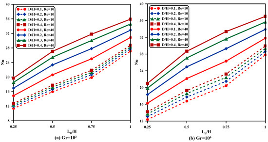
Figure 11.
Nusselt number alterations with partial heating length fraction for numerous values of Reynolds number and inflow to outflow aspect proportion at of and and , (a) , (b) .
4.3. Effect of Outlet Vent Opening Location
Four positions for the outflow aperture vent have been scrutinized in the present study; namely, , , , and . For three of these locations (), streamlines and isotherm contours for inlet outlet ports aspect ratio values of and , , , and are exemplified in Figure 12. It is clearly apparent from this figure that streamlines of the cavity upper part are not affected when the outflow port position ratio is transformed from to and then to . However, the lower cavity part, specifically the lower right corner, perceives a larger area with a zero value of stream function, which indicates a larger region with zero fluid velocity and less convection current strength. As a result, this reduced convection currents’ ascendency confirms conduction heat transfer mode domination and a decrease in the Nusselt number values as the outlet vents are shifted towards the upper right corner. Additionally, it is obvious from Figure 12 that isotherm lines intensify, and the thermal boundary layer becomes more distinct, thus resulting in a higher temperature distribution inside the cavity when the outflow vent position is moved upward. Increasing temperature inside the enclosure is due to the rise in conduction heat mode in addition to imposing fluid that is heated by the bottom wall to flow inside the right half of the cavity toward the outlet’s opening vent. Contrary to the left half of the cavity, the isotherms remain approximately unchanged even when the outflow port location is lifted to the upper right corner. This is owing to the unchanging streamlines and fluid velocity inside this part of the enclosure.
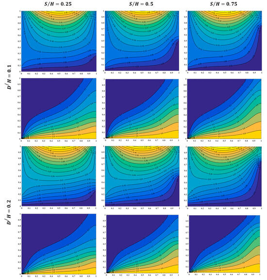
Figure 12.
Streamlines (upper) and isotherms (lower) for different values of and at , , and .
In order to examine the outcome of the outlet vent position on the average Nusselt number for the partial heating length ratio (), the Reynolds number (), and inlet outlet vents aspect ratio () are plotted in Figure 13 and Figure 14 at and , respectively. From these figures, it is obviously elucidated that the average Nusselt number decreases as the outflow opening site is shifted towards the upper cavity right wall for all studied related parameters. At and , Nusselt number decreases by , , , and once the Reynolds number is taken as , , , and respectively, when the outlet port ratio is shifted from position to , while at and , Nusselt number reduces by , , , and when the Reynolds number is taken as , , , and , correspondingly.
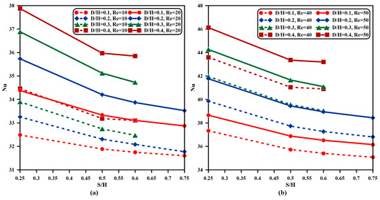
Figure 13.
Nusselt number alterations with outlet vent position fraction for numerous values of Reynolds number and inflow to outflow aspect proportion at and , (a) and , (b) and .
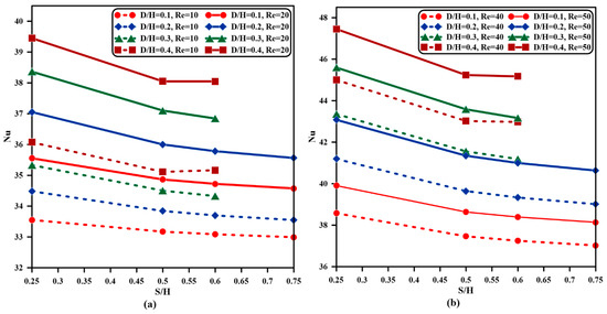
Figure 14.
Nusselt number variations with outflow vent location proportion for numerous values of Reynolds number and inflow to outflow aspect proportion at and (a) and , (b) and .
Additionally, it can be noticed from these figures that the curves of and stop at because the inlet–outlet dimensions exceed the cavity dimensions at these two values. As previously described in Figure 12, when the outlet port location ratio is increased from to , a larger area with zero fluid velocity is occupied inside the enclosure. Thus, the convection currents are weakened with the increase in the outlet port location ratio value, and the domination of heat transfer happens by conduction which results in a Nusselt number reduction. Also, as the outflow opening is transformed towards the upper right corner, the fluid is forced to conduct more with the region above the bottom heated wall which leads to a temperature gradient reduction near the wall and consequently decreases the average Nusselt number value. Moreover, at any position of the outlet vent, the average Nusselt number rises as the Reynolds number increases and the inflow-outflow aspect proportion is augmented for the same reasons discussed previously.
With the purpose of inspecting the effect of outlet vent position and the partial heating length ratio on the average Nusselt number, Figure 15 and Figure 16 are portrayed for inlet–outlet port opening ratios and , respectively. It is evidently detected from these two figures that for all heating length ratios, the Nusselt number decreases with the increase in the outlet vent location ratio and this reduction is higher when . As , , , and , the average Nusselt number diminishes by once the outlet vent location ratio is raised from to while when , the reduction becomes .
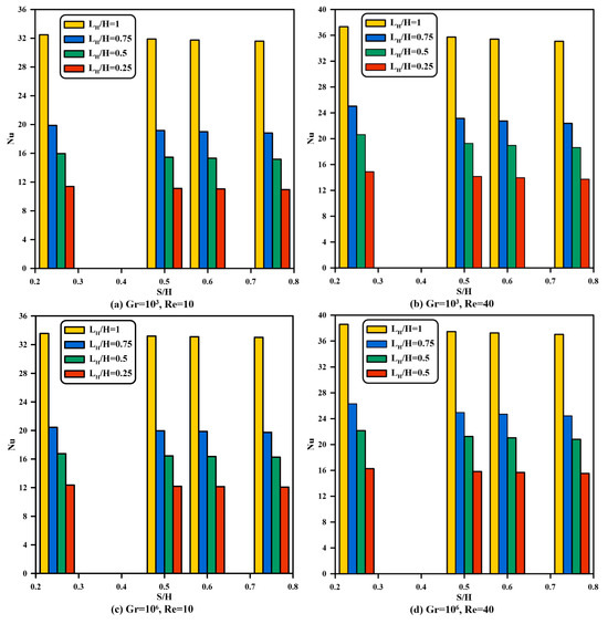
Figure 15.
Nusselt number variations with outflow vent position proportion for different values of partial heating length ratio at .
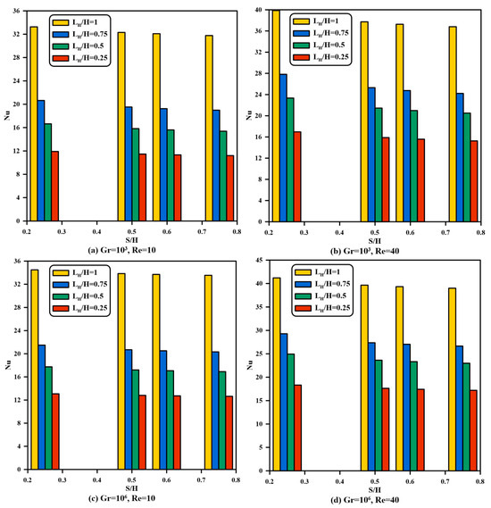
Figure 16.
Nusselt number variations with outflow vent position proportion for different values of partial heating length ratio at .
When , the decreasing percentage is changed into and respectively. The main reason stated behind this action is that the rising outlet port location maintains a lower fluid velocity in the bottom half of the cavity and consequently attenuates convection currents which results in a conduction heat transfer mode ascendency. The conduction mode dominancy leads to a reduction in thermal boundary layer thickness near the heated wall and thus the convection currents upsurge once buoyancy, inertia, and shear flow are weakened with respect to other cases. Hence, the average Nusselt number decreases when the outlet position ratio is enlarged. Moreover, once , , , and , the average Nusselt number reduces by when the outlet vent location ratio is elevated from to while for , the reduction becomes , and when the diminishing proportion is altered into and respectively. It is observable that the decreasing proportions are augmented when the inlet–outlet aspect ratio is amplified from to . This comportment can be attributed to the stream and isotherm lines as has been mentioned previously in the discussion of Figure 10. Increasing the opening vent aspect ratio causes a supplementary quantity of cold fluid to flow into the cavity, and subsequently, a larger temperature gradient takes place, which causes an augmentation in the Nusselt number reduction fraction.
In summary, the quantitative percentages of the averaged Nusselt number alteration with relevant parameters for the selected cases are summarized in Table 3 in order to improve the clarity and accessibility of the results. This supplements the qualitative analysis of streamlines and isotherms and permits for easier assessment amid cases.
Table 3.
Averaged Nusselt number alteration with relevant parameters for selected cases.
5. Conclusions
In the current study, a layer of nanofluid-saturated metal foam confined in a square lid-driven vented enclosure is numerically explored, taking into account thermal dispersion and local thermal non–equilibrium influences. Cooling fluid enters a cavity from an inlet port on the left wall and leaves the cavity from another port made in the opposite wall. The left sidewall is kept at the same cold temperature as the fluid entering the enclosure, and the bottom wall is heated discreetly while other walls are thermally insulated. The heat transfer process is improved further by driving the cavity’s upper wall with a constant speed. The consequence of pertinent parameters is accomplished, which are the Reynolds number, the Grashof number, the inlet and outlet opening ports aspect ratios, the outlet port position ratio, and the partial heating length ratio. The foremost attainments of existing numerical problems can be highlighted as follows:
- Increasing the inflow–outflow opening port aspect proportion creates a greater intensity in the streamline values, which implies higher forced convection currents and creates considerable distinctions in the temperature and flow fields.
- For a value of Grashof number , augmenting the Reynolds number from to does not alter the streamline and isotherms field either quantitively or qualitatively, but when the is taken as , it is observed that the streamline values increase monotonically. Whereas, when , the opposite behavior for fluid and heat transfer fields is specified, and a reduction in temperature as is amplified.
- Increasing from to leads to an adequate augment of the streamline and temperature fields for initiating higher inertia force and thus growing in fluid velocity corresponding to other heating length ratios.
- Isotherm and streamlines are intensified, and the thermal boundary layer becomes more distinct. Thus, there is a higher temperature distribution inside the cavity when the outlet port location is moved upward.
- Fluid and solid Nusselt numbers rise as the Grashof and Reynolds numbers and vent aspect ratio is augmented. Raising the from to at and creates a rise of in fluid-phase and in solid-phase Nusselt numbers, and they increase by and , respectively, as grows from to when and .
- The levitation inflow to outflow ports aspect proportion increase from to at and results in a growth of in fluid-phase and in solid-phase Nusselt numbers.
- Quantitively, the increase in the average Nusselt number as a sum of fluid- and solid-phase Nusselt numbers is almost the same as the increase in each phase individually.
- Nusselt number values do not change as the Grashof number increases from to , while raising the Grashof number from to enhances the Nusselt number.
- Raising from to intensifies with a smaller proportion, whereas raising from to increases with a higher percentage than from to ; when , , and , increases by , , and as , increases by , , and once is amplified from to , to , and to respectively.
- The average Nusselt number decreases as the outflow vent location is shifted towards the upper cavity right wall; at and , decreases by , , , and as , , , and , respectively, when is shifted from position to , while at and , reduces by , , , and when , , , and , respectively.
- For all heating length ratios, the Nusselt number decreases as the outlet vent location ratio increases, and this reduction is higher when ; as , , , and , diminishes by once is raised from to , while when , the reduction becomes , and when , the decreasing percentages are and respectively.
- The presented numerical model and constructed in-home computer code were verified and validated in contrast to accessible published numerical results, confirming their consistency within the studied relevant parameters range. Even though experimental results for the particular problem configuration are not reachable, this constraint is accepted, and experimental work for this problem will be focused on in the future.
6. Limitations and Future Work
The current study includes some hypotheses that were specified for the purpose of simplifying heat transfer problems and formulating mathematical models and numerical simulations. These postulations generate a number of limitations when existing mathematical modeling and numerical simulation are utilized to inspect the fluid flow and heat transmission in similar lid-driven vented cavity systems that are employed in technical and engineering applications. According to the aforementioned mathematical model and simulation stated assumptions, the present work is limited to a two-dimensional, steady-state, incompressible, single phase and laminar flow, and radiative heat transmission and viscous energy dissipation inspirations are thought to be irrelevant. Additionally, it is hypothesized that metal foam is hydrodynamically and thermally isotropic, homogeneous, and saturated with single-phase nanofluid which is in local thermal non-equilibrium with metal foam solid matrices. Consequently, contemporary mathematical modeling is not suitable for thermal arrangements of high Reynolds numbers, turbulent fluid flow, and crossed by non-uniform metal foam. Moreover, high temperature appliances where radiation or nonlinear property distinction is remarkable are omitted from employing existing heat transmission models. Additionally, the present numerical simulation has not been validated with the experimental study of exact current configuration because, as per the authors’ knowledge, no such experimental data are presently accessible in the literature. However, future work will be specialized for experimental validation to the contemporary model and extending existing simulations to analyze various geometrical configurations and boundary conditions. Also, future study should be accompanied by a developed control system in order to regulate the moving lid and inflow fluid velocities.
Author Contributions
Conceptualization, A.J.H. and L.F.A.; methodology, L.F.A.; validation, A.J.H., S.A.A.-S. and L.F.A.; formal analysis, A.J.H.; investigation, L.F.A.; writing—original draft preparation, L.F.A.; writing—review and editing, A.J.H. and S.A.A.-S.; supervision, A.J.H.; funding acquisition, S.A.A.-S. and L.F.A. All authors have read and agreed to the published version of the manuscript.
Funding
This study is financially not reinforced by any organization and fees is paid by authors.
Data Availability Statement
The original contributions presented in this study are included in the article. Further inquiries can be directed to the corresponding author(s).
Conflicts of Interest
The authors declare no conflicts of interest.
Abbreviations
The following abbreviations are used in this manuscript:
| PPI | Pores Per Inch |
References
- Selimefendigil, F.; Oztop, H.F. Convection and Phase Change in a Lid-Driven Trapezoidal Vented Cavity with Encapsulated PCM under Non-Uniform Magnetic Field by Using Ternary Nanofluid. Therm. Sci. Eng. Prog. 2024, 48, 102424. [Google Scholar] [CrossRef]
- Nield, D.A.; Bejan, A. Convection in Porous Media; Springer International Publishing: Cham, Switzerland, 2017. [Google Scholar] [CrossRef]
- Kaviany, M. Principles of Heat Transfer in Porous Media; Springer Science & Business Media: New York, NY, USA, 1995. [Google Scholar] [CrossRef]
- Abdulwahed, A.S.; Ali, L.F. Numerical Investigation of Natural Convection in a Square Enclosure Partially Filled with Horizontal Layers of a Porous Medium. Heat Transf. 2023, 52, 874–889. [Google Scholar] [CrossRef]
- Zachi, F.J.; Ali, L.F. Experimental Study of Natural Convection Heat Transfer on an Enclosure Partially Filled Porous Medium Heated from below by Constant Heat Flux. AIP Conf. Proc. 2023, 2651, 050002. [Google Scholar] [CrossRef]
- Alkinani, I.H.; Ali, L.F. 2022 Natural Convection in Annulus between Two Concentric Cylinders Partially Filled with Metal Foam Distributed with New Suggested Design. In IOP Conference Series: Earth and Environmental Science; IOP Publishing Ltd.: Bristol, UK, 2024. [Google Scholar] [CrossRef]
- Ali, L.F.; Humaidi, A.J. Offset Temperature and Amplitude–Frequency Effect on Convection Heat Transfer in Partially Gradient Porous Cavity with Different Outlet Port Locations. Processes 2025, 13, 2279. [Google Scholar] [CrossRef]
- Ali, L.F.; Togun, H.; Sadeq, A.M. Effect of Heated Wall Corrugation on Thermal Performance in an L-Shaped Vented Cavity Crossed by Metal Foam Saturated with Copper-Water Nanofluid. Computation 2025, 13, 218. [Google Scholar] [CrossRef]
- Ali, L.F.; AL-Samarraie, S.A.; Humaidi, A.J. Performance of Double Pipe Heat Exchanger—Partially Occupied by Metal Foam—Is Better Enhanced Using Robust Adaptive Barrier Function-Based Sliding Mode Control. Energies 2025, 18, 4671. [Google Scholar] [CrossRef]
- Choi, S.U.S.; Eastman, J.A.; Eastman, J.A. Enhancing thermal conductivity of fluids with nanoparticles. In ASME International Mechanical Engineering Congress and Exposition; American Society of Mechanical Engineers: New York, NY, USA, 1995. [Google Scholar]
- Daungthongsuk, W.; Wongwises, S. A Critical Review of Convective Heat Transfer of Nanofluids. Renew. Sustain. Energy Rev. 2007, 11, 797–817. [Google Scholar] [CrossRef]
- Mahmoudi, Y.; Hooman, K.; Vafai, K. Convective Heat Transfer in Porous Media; CRC Press: Boca Raton, FL, USA, 2019. [Google Scholar] [CrossRef]
- Tien, H.-C.; Chiang, K.-S. Non-Darcy Flow and Heat Transfer in a Porous Insulation with Infiltration and Natural Convection. J. Mar. Sci. Technol. 1999, 7, 8. [Google Scholar]
- Ghazanfarian, J.; Abbassi, A. Mixed Convection in a Square Cavity Filled with a Porous Medium and Different Exit Port Position. J. Porous Media 2007, 10, 701–718. [Google Scholar] [CrossRef]
- Bhuiyan, A.A.; Banna, M.H.; Barna, S.F.; Amin, M.R.; Sadrul Islam, A.K.M. Numerical Modelling of Thermal Characteristics in a Microstructure Filled Porous Cavity with Mixed Convection. Int. J. Heat Mass Transf. 2016, 93, 464–476. [Google Scholar] [CrossRef]
- Mahmud, S.; Pop, I. Mixed Convection in a Square Vented Enclosure Filled with a Porous Medium. Int. J. Heat Mass Transf. 2006, 49, 2190–2206. [Google Scholar] [CrossRef]
- Krishna Murthy, S.V.S.S.N.; Kumar, B.V.R. Non-Darcy Mixed Convection in a Porous Square Enclosure under Suction/Injection Effects with a Non-Isothermal Vertical Wall. Numer. Heat Transf. A Appl. 2010, 57, 580–602. [Google Scholar] [CrossRef]
- Rathish Kumar, B.V.; Krishna Murthy, S.V.S.S.N.V.G. Mixed Convection in a Non-Darcian Fluid Saturated Square Porous Enclosure under Multiple Suction Effect. Int. J. Heat Mass Transf. 2010, 53, 5764–5773. [Google Scholar] [CrossRef]
- Krishna Murthy, S.V.S.S.N.; Kumar, B.V.R. Darcy Mixed Convection in a Fluid Saturated Square Porous Enclosure under Multiple Suction Effect. Int. J. Numer. Methods Heat Fluid Flow 2011, 21, 602–617. [Google Scholar] [CrossRef]
- Behzadi, T.; Shirvan, K.M.; Mirzakhanlari, S.; Sheikhrobat, A.A. Numerical Simulation on Effect of Porous Medium on Mixed Convection Heat Transfer in a Ventilated Square Cavity. Procedia Eng. 2015, 127, 221–228. [Google Scholar] [CrossRef][Green Version]
- Ali, L.F. Natural and Mixed Convection in Square Vented Enclosure Filled with Metal Foam. J. Eng. 2015, 21, 60–79. [Google Scholar] [CrossRef]
- Sheremet, M.A.; Roşca, N.C.; Roşca, A.V.; Pop, I. Mixed Convection Heat Transfer in a Square Porous Cavity Filled with a Nanofluid with Suction/Injection Effect. Comput. Math. Appl. 2018, 76, 2665–2677. [Google Scholar] [CrossRef]
- Ataei-Dadavi, I.; Chakkingal, M.; Kenjeres, S.; Kleijn, C.R.; Tummers, M.J. Experiments on Mixed Convection in a Vented Differentially Side-Heated Cavity Filled with a Coarse Porous Medium. Int. J. Heat Mass Transf. 2020, 149, 119238. [Google Scholar] [CrossRef]
- Ahmed, S.E. Caputo Fractional Convective Flow in an Inclined Wavy Vented Cavity Filled with a Porous Medium Using Al2O3—Cu Hybrid Nanofluids. Int. Commun. Heat Mass Transf. 2020, 116, 104690. [Google Scholar] [CrossRef]
- Ullah, N.; Nadeem, S.; Saleem, A. Finite Element Analysis of Convective Nanofluid Equipped in Enclosure Having Both Inlet and Outlet Zones. J. Taiwan Inst. Chem. Eng. 2020, 113, 428–441. [Google Scholar] [CrossRef]
- Alawee, W.H.; Al-Sumaily, G.F.; Dhahad, H.A.; Thompson, M.C. Numerical Analysis of Non-Darcian Mixed Convection Flows in a Ventilated Enclosure Filled with a Fluid-Saturated Porous Medium. Therm. Sci. Eng. Prog. 2021, 24, 100922. [Google Scholar] [CrossRef]
- Hazra, C.; Biswas, N.; Manna, N.K. Thermal Magneto-Hydrodynamics in a Ventilated Porous Enclosure. Sādhanā 2020, 45, 224. [Google Scholar] [CrossRef]
- Hussain, S.; Öztop, H.F.; Alsharif, A.M.; Ertam, F. Mixed Bioconvection of Nanofluid of Oxytactic Bacteria through a Porous Cavity with Inlet and Outlet under Periodic Magnetic Field Using Artificial Intelligence Based on LightGBM Algorithm. Therm. Sci. Eng. Prog. 2024, 50, 102589. [Google Scholar] [CrossRef]
- Khanafer, K.M.; Chamkhaa, A.J. Mixed Convection in a Lid-Driven Enclosure Filled with a Fluid-Saturated Porous Medium. PERGAMON Int. J. Heat Mass Transf. 1999, 42, 2465–2481. [Google Scholar] [CrossRef]
- Al-Amiri, A.M. Analysis of momentum and energy transfer in a lid-driven cavity filled with a porous medium. Int. J. Heat Mass Transf. 2000, 43, 3513–3527. [Google Scholar] [CrossRef]
- Oztop, H.F. Combined Convection Heat Transfer in a Porous Lid-Driven Enclosure Due to Heater with Finite Length. Int. Commun. Heat Mass Transf. 2006, 33, 772–779. [Google Scholar] [CrossRef]
- Kandaswamy, P.; Muthtamilselvan, M.; Lee, J. Prandtl Number Effects on Mixed Convection in a Lid-Driven Porous Cavity. J. Porous Media 2008, 11, 791–801. [Google Scholar] [CrossRef]
- Jeng, T.M.; Tzeng, S.C. Heat Transfer in a Lid-Driven Enclosure Filled with Water-Saturated Aluminum Foams. Numer. Heat Transf. A Appl. 2008, 54, 178–196. [Google Scholar] [CrossRef]
- Basak, T.; Roy, S.; Singh, S.K.; Pop, I. Analysis of Mixed Convection in a Lid-Driven Porous Square Cavity with Linearly Heated Side Wall(s). Int. J. Heat Mass Transf. 2010, 53, 1819–1840. [Google Scholar] [CrossRef]
- Basak, T.; Krishna Pradeep, P.V.; Roy, S.; Pop, I. Finite Element Based Heatline Approach to Study Mixed Convection in a Porous Square Cavity with Various Wall Thermal Boundary Conditions. Int. J. Heat Mass Transf. 2011, 54, 1706–1727. [Google Scholar] [CrossRef]
- Ramakrishna, D.; Basak, T.; Roy, S.; Pop, I. Numerical Study of Mixed Convection within Porous Square Cavities Using Bejan’s Heatlines: Effects of Thermal Aspect Ratio and Thermal Boundary Conditions. Int. J. Heat Mass Transf. 2012, 55, 5436–5448. [Google Scholar] [CrossRef]
- Sivasankaran, S.; Pan, K.L. Numerical Simulation on Mixed Convection in a Porous Lid-Driven Cavity with Nonuniform Heating on Both Side Walls. Numer. Heat Transf. A Appl. 2012, 61, 101–121. [Google Scholar] [CrossRef]
- Basak, T.; Roy, S.; Chamkha, A.J. A Peclet Number Based Analysis of Mixed Convection for Lid-Driven Porous Square Cavities with Various Heating of Bottom Wall. Int. Commun. Heat Mass Transf. 2012, 39, 657–664. [Google Scholar] [CrossRef]
- Rahman, M.M.; Oztop, H.F.; Saidur, R.; Mekhilef, S.; Al-Salem, K. Unsteady Mixed Convection in a Porous Media Filled Lid-Driven Cavity Heated by a Semi-Circular Heaters. Therm. Sci. 2015, 19, 1761–1768. [Google Scholar] [CrossRef]
- Muthtamilselvan, M.; Sureshkumar, S. Convective Heat Transfer in a Porous Enclosure Saturated by Nanofluid with Different Heat Sources. Nonlinear Eng. 2018, 7, 1–16. [Google Scholar] [CrossRef]
- Hussain, S.; Mehmood, K.; Sagheer, M.; Yamin, M. Numerical Simulation of Double Diffusive Mixed Convective Nanofluid Flow and Entropy Generation in a Square Porous Enclosure. Int. J. Heat Mass Transf. 2018, 122, 1283–1297. [Google Scholar] [CrossRef]
- Muthukumar, S.; Sureshkumar, S.; Chamkha, A.J.; Muthtamilselvan, M.; Prem, E. Combined MHD Convection and Thermal Radiation of Nanofluid in a Lid-Driven Porous Enclosure with Irregular Thermal Source on Vertical Sidewalls. J. Therm. Anal. Calorim. 2019, 138, 583–596. [Google Scholar] [CrossRef]
- Marzougui, S.; Mebarek-Oudina, F.; Magherbi, M.; Mchirgui, A. Entropy Generation and Heat Transport of Cu–Water Nanoliquid in Porous Lid-Driven Cavity through Magnetic Field. Int. J. Numer. Methods Heat Fluid Flow 2022, 32, 2047–2069. [Google Scholar] [CrossRef]
- Laidoudi, H.; Abderrahmane, A.; Saeed, A.M.; Guedri, K.; Weera, W.; Younis, O.; Mourad, A.; Marzouki, R. Irreversibility Interpretation and MHD Mixed Convection of Hybrid Nanofluids in a 3D Heated Lid-Driven Chamber. Nanomaterials 2022, 12, 1747. [Google Scholar] [CrossRef]
- Maneengam, A.; Bouzennada, T.; Abderrahmane, A.; Guedri, K.; Weera, W.; Younis, O.; Bouallegue, B. Numerical Study of Lid-Driven Hybrid Nanofluid Flow in a Corrugated Porous Cavity in the Presence of Magnetic Field. Nanomaterials 2022, 12, 2390. [Google Scholar] [CrossRef]
- Yaseen, D.T.; Salih, S.M.; Ismael, M.A. Effect of the Lid-Driven on Mixed Convection in an Open Flexible Wall Cavity with a Partially Heated Bottom Wall. Int. J. Therm. Sci. 2023, 188, 108213. [Google Scholar] [CrossRef]
- Yaseen, D.T.; Ismael, M.A.; Salih, S.M. Discrete Heating of Turbulent FSI in a Vented Lid-Driven Enclosure. Int. Commun. Heat Mass Transf. 2024, 158, 107910. [Google Scholar] [CrossRef]
- Ghashim, S.L. A Mathematical Analysis of Nanoparticles on Heat Transfer in a Circular Pipe. Case Stud. Therm. Eng. 2021, 28, 101524. [Google Scholar] [CrossRef]
- Al-Farhany, K.; Abdulsahib, A.D. Study of Mixed Convection in Two Layers of Saturated Porous Medium and Nanofluid with Rotating Circular Cylinder. Prog. Nucl. Energy 2021, 135, 103723. [Google Scholar] [CrossRef]
- Messaoud, H.; Adel, S.; Ouerdia, O. Mixed Convection Heat Transfer of a Nanofluid in a Square Ventilated Cavity Separated Horizontally by a Porous Layer and Discrete Heat Source. Arch. Thermodyn. 2023, 44, 87–114. [Google Scholar] [CrossRef]
- Alsabery, A.I.; Chamkha, A.J.; Saleh, H.; Hashim, I. Natural Convection Flow of a Nanofluid in an Inclined Square Enclosure Partially Filled with a Porous Medium. Sci. Rep. 2017, 7, 2357. [Google Scholar] [CrossRef] [PubMed]
- Balla, C.S.; Kishan, N.; Gorla, R.S.R.; Gireesha, B.J. MHD Boundary Layer Flow and Heat Transfer in an Inclined Porous Square Cavity Filled with Nanofluids. Ain Shams Eng. J. 2017, 8, 237–254. [Google Scholar] [CrossRef]
- Xu, H.; Gong, L.; Huang, S.; Xu, M. Flow and Heat Transfer Characteristics of Nanofluid Flowing through Metal Foams. Int. J. Heat Mass Transf. 2015, 83, 399–407. [Google Scholar] [CrossRef]
- Calmidi, V.V.; Mahajan, R.L. Forced Convection in High Porosity Metal Foams. J. Heat Transf. 2000, 122, 557–565. [Google Scholar] [CrossRef]
- Patankar, S.V. Numerical Heat Transfer and Fluid Flow; Taylor & Francis Publishers: New York, NY, USA, 1980. [Google Scholar] [CrossRef]


Disclaimer/Publisher’s Note: The statements, opinions and data contained in all publications are solely those of the individual author(s) and contributor(s) and not of MDPI and/or the editor(s). MDPI and/or the editor(s) disclaim responsibility for any injury to people or property resulting from any ideas, methods, instructions or products referred to in the content. |
© 2025 by the authors. Licensee MDPI, Basel, Switzerland. This article is an open access article distributed under the terms and conditions of the Creative Commons Attribution (CC BY) license (https://creativecommons.org/licenses/by/4.0/).