Abstract
To address the issue that the current research on TBM disc cutter rock breaking insufficiently considers actual stratified rock masses, this study constructs numerical models of stratified rock masses with different bedding dip angles and bedding spacings based on the discrete element method (DEM). The whole process of TBM disc cutter rock breaking is numerically simulated through the displacement loading mode. The research results show that the bedding dip angle has a significant impact on the crack propagation mode. When α = 45°, the bedding intersects with the contact point of the disc cutter, and cracks penetrate directly along the bedding without an obvious “crushed zone”, resulting in the minimum number of cracks. The bedding spacing regulates the rock-breaking effect in stages. When d = 45°, the “crushed zone” interacts with two beddings to form three branch cracks, reaching the peak number of cracks and achieving the optimal rock-breaking efficiency. The cracks generated by disc cutter rock breaking exhibit the characteristic of “slow initial growth and rapid later surge” with the increase in time steps, which is highly consistent with the actual mechanical process of rock breaking. This study reveals the influence mechanism of bedding properties on TBM disc cutter rock breaking, verifies the reliability of the DEM combined with PB and SJ models in the simulation of stratified rock mass breaking, and provides theoretical support and data references for the parameter optimization of TBM disc cutters and efficient tunneling under complex stratified geological conditions.
1. Introduction
Against the backdrop of the global infrastructure development extending toward deep layers and complex geological conditions, Tunnel Boring Machines (TBMs) have become core equipment for the construction of subways, river-crossing tunnels, water diversion tunnels, and mine roadways due to their advantages of high efficiency, safety, and environmental protection. TBMs are mainly classified based on the geological conditions of excavations: Open-Type Hard Rock TBMs are designed for hard rock strata (such as granite and sandstone), relying on disc cutters to crush rock directly; Earth Pressure Balance (EPB) TBMs are suitable for soft soil or sand–gravel strata, maintaining tunnel face stability by balancing the pressure of muck in the soil cabin; Slurry Shield TBMs are commonly used in high-water-pressure or easily collapsible soft soil strata, using slurry to support the tunnel face and carry muck. As the key components of TBMs that directly interact with hard rocks, disc cutters determine the overall tunneling efficiency, construction cost, and engineering safety of the entire machine [1,2]. Therefore, research on TBM disc cutter rock breaking is of great practical necessity. On one hand, as engineering projects advance into deep strata, the encountered rock strength continues to increase, and the geological conditions become more complex (such as high-hardness granite, fracture zones, and alternating hard and soft layers). Traditional disc cutters often suffer from problems such as excessive wear, a sharp drop in rock-breaking efficiency, and even cutterhead jamming. Taking a deep-buried water diversion tunnel project as an example, the average service life of disc cutters in hard rock sections is only 60% of the designed value, and frequent cutter replacement has led to a construction period delay of more than 30% [3,4,5]. This significantly increases construction costs and safety risks, so in-depth research on the rock-breaking mechanism of disc cutters is urgently needed to optimize the cutter structure and rock-breaking parameters, thereby enhancing their adaptability to complex geological conditions. On the other hand, most of the current research on TBM disc cutter rock breaking is based on the working condition of ideal homogeneous rocks, with insufficient consideration of factors such as rock heterogeneity and the stress state in actual engineering. This leads to large deviations between theoretical calculations and on-site construction, making it difficult to effectively guide cutter selection, cutterhead design, and tunneling parameter optimization [6,7]. However, through systematic research on the TBM disc cutter rock-breaking process, the rock fragmentation law and the force characteristics of disc cutters can be revealed. This not only bridges the gap between theory and practice but also provides technical support for the development of high-efficiency disc cutters and the construction of intelligent tunneling control systems. It is of great theoretical significance and engineering application value for promoting the development of tunnel engineering toward high efficiency and intelligence and ensuring the smooth implementation of major infrastructure projects.
Experimental research on TBM disc cutter rock breaking can provide accurate technical support for tunnel construction. Its core advantage lies in the ability to simulate real engineering scenarios. By controlling variables such as rock properties, disc cutter parameters, thrust, and rotational speed, the correlation between disc cutter rock-breaking efficiency and energy consumption can be quantitatively analyzed, providing direct data support for cutter selection, cutter arrangement, and construction parameter optimization. Experiments can also expose potential engineering problems in advance, such as the wear law of disc cutters and the impact of rock slag morphology on the slag discharge system, thereby reducing on-site construction risks and cost waste. Meanwhile, relying on the repeatability and controllability of laboratory experiments, multiple sets of comparative experiments can be conducted to deeply explore the rock-breaking mechanism under the interaction of different factors and promote the innovation of rock-breaking theories, laying a foundation for the development of new disc cutters and the upgrading of TBM models. For example, Zhang [8] proposed a distributed laser (DL) model and a detachable optical lens assembly. Through micro-scratch tests and macro-scaled-down disc cutter indentation tests, it was confirmed that DL can effectively inhibit the formation of glass glaze, reduce rock-breaking energy consumption, and improve TBM rock-breaking efficiency, thus revealing its auxiliary rock-breaking mechanism. Yang [9] conducted TBM disc cutter indentation tests on microwave-damaged rocks under initial stress conditions for the first time. Combined with acoustic emission, digital image correlation, and the discrete element method, it was found that there is a threshold for initial stress, microwave irradiation can reduce this threshold, and high microwave power has a more significant auxiliary rock-breaking effect under high initial stress. Gu [10] studied the influence of pre-grooving depth on rock-breaking force, specific energy consumption, and rock chip distribution through linear cutting tests of disc cutters and discrete element simulations. It was found that an appropriate pre-grooving depth can guide crack propagation, reduce rock-breaking force and specific energy consumption, and the rock chip roughness index (CI) can effectively evaluate rock-breaking efficiency. However, experimental research on TBM disc cutter rock breaking has obvious limitations. Firstly, there are differences between experimental scenarios and actual engineering. Laboratory experiments cannot fully replicate the complex on-site geological conditions, such as the dynamic changes in natural factors, including the degree of rock joint development and in situ stress distribution, which may lead to deviations between experimental data and on-site construction effects. Secondly, the experimental cost is relatively high. Large-scale physical experiments require the construction of professional platforms and the purchase of high-precision equipment, and a single experiment takes a long time, making it difficult to quickly respond to diverse engineering needs. In addition, experiments mostly focus on the analysis of a single or a few variables, and the simulation of the rock-breaking process under the coupling effect of multiple factors is not comprehensive. Especially, the research on the rock-breaking law of special lithologies (such as extremely hard rocks and weak interlayers) still has shortcomings.
Theoretical research on TBM disc cutter rock breaking is the key to revealing the essence of rock breaking, and its advantage lies in the ability to analyze the interaction law between disc cutters and rock masses from the mechanism level. By establishing mechanical models (such as Hertz contact theory and the rock fracture mechanics model), the internal correlation between disc cutter thrust, torque, and rock breaking energy consumption as well as crack propagation can be quantitatively analyzed. This breaks through the variable limitations of physical experiments and deeply explores the influence of single-factor or multi-factor coupling on rock-breaking effects. For example, Zhang [11] proposed a distributed laser theoretical model with adjustable power density. Qi [12] established a method for calculating excavation loads considering the rotation of disc cutters and the difference in load distribution and proposed an efficiency optimization method aiming at minimizing specific energy combined with energy analysis. Liu [13] proposed a method for calculating the sampling volume of rock chips based on the Jiajin Mountain TBM tunnel project and verified the multifractal characteristics of the particle size distribution of sandstone and slate chips. Nevertheless, the theoretical research on TBM disc cutter rock breaking has significant limitations. The primary problem is the mismatch between the simplification of theoretical models and the complexity of actual working conditions. Most existing theories are based on the assumption of homogeneous and continuous rock masses, ignoring the dynamic changes of in situ factors such as joint fissures, heterogeneity, and in situ stress of on-site rock masses. This leads to deviations between the calculation results of the models and the actual engineering conditions. Secondly, the theoretical research is insufficient in describing the coupling effect of multiple factors. For example, the dynamic correlation between disc cutter wear, rock slag accumulation, and rock-breaking efficiency has not yet formed a complete quantitative model, making it difficult to fully reflect the complex rock-breaking process on-site. In addition, some theoretical achievements rely on the verification of ideal test conditions and lack the support of large-scale engineering data. This results in insufficient adaptability when the theories are transformed into practical applications, especially in special scenarios such as extremely hard rocks and highly abrasive rocks, where the guiding role of theories is limited and cannot fully meet the needs of accurate engineering construction.
There are mainly three types of numerical simulation methods for TBM disc cutter rock breaking: the continuous finite element method (FEM), meshless smoothed particle hydrodynamics (SPH), and the discrete element/particle flow method (DEM/PFC). The finite element method is relatively mature, with high calculation efficiency, making it suitable for parameter sweeping and design optimization. It can naturally couple the dynamics of the cutterhead/entire machine, facilitating structural strength and system dynamics analysis. The rock-breaking process can be approximately simulated through “element birth and death” or damage criteria. For example, Xia et al. [14] simulated the rock-breaking process of a single TBM disc cutter near the side free surface in Baiyun granite by combining the finite element method (FEM) with the JH-2 model and the Rankine tensile cracking softening model. Wen et al. [15] addressed the research gap in the rock-breaking efficiency of TBM disc cutters in composite rocks (sandstone–granite) with significant strength differences. Through finite element numerical simulation combined with full-scale laboratory test verification, the similarities and differences between composite rock breaking and homogeneous rock breaking were revealed. However, the FEM is essentially a continuous-medium method, making it difficult to handle discontinuous behaviors such as large deformation and crack penetration. It is prone to the problem of “excessive breaking under the cutter and insufficient breaking between cutters” and has weak ability to describe joints and complex fractures. Moreover, the material constitutive model and on-site mapping require a large amount of calibration, leading to general adaptability to complex geology. Smoothed particle hydrodynamics is a meshless method that can adaptively handle large deformation, fracture, and splashing without mesh redivision. It can be coupled with the FEM to form a Lagrange–SPH framework and has a high degree of agreement with experiments in terms of cutter–rock impact and fracture morphology. For example, Hajivand et al. [16] used a bond-based peridynamics framework in LS-DYNA to numerically simulate the Linear Cutting Machine (LCM) test of Colorado red granite and explore the rock-breaking process of TBM disc cutters. Zhang et al. [17] established a three-dimensional numerical model of TBM disc cutter cutting of Chongqing sandstone based on the SPH method to optimize TBM disc cutter parameters and improve rock-breaking efficiency and verified the effectiveness of the model through laboratory tests. Cai et al. [18] adopted an SPH/FEM coupling model to explore the composite rock-breaking mechanism from the perspectives of rock stress field, cutting force, and jet field, aiming at the unclear mechanism of composite rock breaking by a high-pressure CO2 jet and PDC cutter in CO2 underbalanced drilling, combined with experiments. However, the failure threshold and contact handling of SPH are sensitive and require strict calibration, and the efficiency and stability of multi-cutter and large-scale models still pose challenges. The discrete element method can naturally describe discontinuous deformation, joints, and the entire rock-breaking process, and it can explicitly track the initiation, propagation, and penetration of microcracks. The mesoscopic parameters can be calibrated and connected with laboratory tests, facilitating mechanism research, and it has a strong ability to describe the influence of structural planes such as joints and beddings. For example, Jiang et al. [19] established a numerical model of disc cutter rock breaking based on the Particle Flow Code (PFC). After verifying the effectiveness of the model through physical rock-breaking tests, the mechanism of free-face-assisted disc cutter rock breaking and the influence of cutting parameters were explored. Wang et al. [20] established a two-dimensional discrete element (DE) model to optimize the tooth structure of inserted disc cutters for Raise Boring Machines (RBMs) and improve hard rock-breaking efficiency. The mesoscopic parameters of granite and sandstone were calibrated through uniaxial compression tests, and the influence of different tooth shapes (conical, saddle-shaped, and wedge-shaped) and working parameters (penetration depth) on rock-breaking characteristics was simulated. Liu et al. [21] explored the influence of static–dynamic coupled loading on the rock-breaking characteristics of TBM disc cutters through scaled-down linear cutting tests and finite discrete element method (FDEM) simulations. Zhang et al. [22] used an improved DEM to model the hydraulic fracturing in a deep reservoir; Dong et al. [23] used the combined approach of the DEM and pipe network flow model to simulate the rock hydraulic fracturing processes; Krzaczek et al. [24] simulated a small-scale hydraulic fracturing process in rock specimens possessing a single injection slot. The advantages and disadvantages of three kinds of numerical methods are listed in Table 1.

Table 1.
Advantages and disadvantages of numerical methods.
Although the existing experimental, theoretical, and numerical studies on TBM disc cutter rock breaking have laid a foundation for tunnel engineering, critical gaps remain: most focus on ideal homogeneous rocks, overlook the coupled effects of bedding parameters (dip angle α and spacing d), or lack systematic verification of the discrete element method (DEM) for stratified rocks—disconnecting theory from practice. Based on the shortcomings of the previous studies, this paper establishes numerical models with different bedding dip angles and spacings based on the discrete element method, carries out numerical simulations of the entire TBM disc cutter rock-breaking process, obtains the law of crack propagation, and explores the influence mechanism of bedding properties on the disc cutter rock-breaking effect. The research results provide a reference for a comprehensive understanding of the TBM disc cutter rock-breaking mechanism.
2. Basic Principles of PFC
2.1. PB Model
In the field of rock failure mechanism research, the discrete element method (DEM) has become a key analytical tool due to its core advantages of capturing discontinuous failure processes and characterizing multi-scale damage features. Compared with FEM, DEM does not need to re-divide the mesh grids around the fissure tips. In this study, the two-dimensional Particle Flow Code (PFC2D) is selected for relevant simulation work. The core principles of this code lie in the real-time tracking of the movement trajectories of discrete particles, solving the system’s dynamic equilibrium equations to calculate particle displacements, and ultimately achieving accurate characterization of the mesoscopic mechanical behavior of rocks.
The simulation process adopts the Parallel Bond (PB) model. Its mechanism of action is as follows: an elastic cementation layer with a defined stiffness is constructed in the contact area between adjacent particles so as to equivalently simulate the cementation effect between particles inside real rocks. After the model is officially activated, the particles are initially in a bonded state. At this stage, the relative movement of particles can trigger the generation of contact forces and moments; when the local stress exceeds the bond strength threshold, the bond will break and induce cracks, and the particle state will then transition to an unbonded state. In this unbonded state, the mechanical action is transmitted only through direct contact between particles, which is specifically manifested as the interaction between tensile force and friction force. This characteristic is highly consistent with the actual mechanical response of rocks after failure.
2.2. SJ Model
The Smooth Joint (SJ) model is mainly used to simulate the smooth contact interface between particles, and it is particularly suitable for simulating weak structural planes such as beddings. This model assumes that the contact between particles is smooth, which does not transmit moments but only transmits normal forces and tangential forces. In the SJ model, the calculation of normal force and tangential force is based on Coulomb’s friction law. That is, the normal force Fn depends on the overlap between particles, and the tangential force Fs must satisfy the following condition:
In the formula, μ is the friction coefficient. When the tangential force reaches the friction limit, relative sliding will occur between particles. This characteristic can well simulate the sliding behavior of bedding planes under stress, which is consistent with the actual situation that beddings, as weak structural planes in rock masses, have relatively weak mechanical properties. In the study of stratified rock masses in this paper, the SJ model can be used to accurately describe the mechanical behavior between particles at the bedding position, simulate phenomena such as sliding and separation of beddings during the stress process, and provide an effective tool for studying the influence of beddings on the rock mass fracture process.
3. Numerical Model, Calculation Scheme, and Parameters
3.1. Numerical Model and Calculation Parameters
The numerical simulation is from a cognitive aspect. Figure 1 shows a schematic diagram of the PFC numerical model containing beddings used in this study. The bedrock part is simulated by the PB model, while the bedding plane part is realized by adding and replacing the SJ model. The model has a size of 1500 mm × 1000 mm, with a disc cutter placed above it. The disc cutter is generated using the Wall command in PFC, and the displacement loading mode is adopted to realize the penetration of the disc cutter into the bedrock. The mesoscopic parameters of PFC used in this study are obtained based on previous experience in parameter selection and trial calculations, as shown in Table 2.
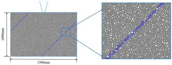
Figure 1.
Schematic diagram of the numerical model.
Table 2.
Mesoscopic parameters of PFC.
3.2. Calculation Scheme
To explore the influence of the structural characteristics of internal beddings in rock masses on the rock-breaking effect of TBM disc cutters, the following calculation schemes are set up: Scheme A focuses on different bedding dip angles, where the angle between the bedding direction and the horizontal direction is defined as α; Scheme B focuses on different bedding spacings, where the vertical distance between beddings is defined as d. The specific calculation schemes are shown in Table 3.
Table 3.
Calculation schemes.
4. Numerical Simulation Results
4.1. Influence of Bedding Dip Angle on Rock-Breaking Law of TBM Disc Cutter
As shown in Figure 2, the bedding dip angle (α) exerts a significant impact on the crack propagation mode of TBM disc cutter rock breaking, and this influence is closely coupled with the mechanical behaviors of the PB (Parallel Bond) model and SJ (Smooth Joint) model in the PFC2D numerical model—where the PB model simulates the cementation between bedrock particles and the SJ model simulates the sliding characteristics of weak bedding planes. As shown in Figure 2, when α = 0° (horizontal bedding), cracks first originate at the contact surface between the disc cutter and bedrock, with conical cracks appearing at the edge of the disc cutter to form a “crushed zone” at the contact point; as the disc cutter continues to penetrate, the “crushed zone” expands gradually, and “radial cracks” are generated directly below the “crushed zone”, extending along the disc cutter penetration direction into the bedrock interior, and, when these radial cracks reach the bedding plane, they penetrate along the bedding and propagate along the horizontal bedding, eventually leading to bedrock surface failure. When α = 30°, a “crushed zone” is also formed at the cutter–bedrock contact surface, and several “branch cracks” are produced around the “crushed zone” during its formation, which intersect with the 30° bedding and then propagate along the bedding direction to cause bedrock failure. When α = 45°, the bedding intersects with the contact point between the disc cutter and bedrock, so no large-scale “crushed zone” is formed during the disc cutter’s penetration into the bedrock; instead, cracks directly propagate and penetrate along the 45° bedding direction, resulting in model failure and the minimum number of cracks among all dip angle conditions. When α = 60°, a “crushed zone” is formed at the cutter–bedrock contact surface, and several “branch cracks” extend from the “crushed zone” and propagate to adjacent bedding planes, leading to crack failure along the bedding. When α = 75°, its crack propagation mode is similar to that at α = 60°, with the only difference being that the “branch cracks” propagate along the 75° dip angle bedding. The most valuable result of this analysis is that the bedding dip angle of 45° is a critical condition for TBM disc cutter rock breaking in stratified rock masses. This dip angle makes the bedding intersect with the cutter–rock contact point, enabling cracks to penetrate directly along the bedding without forming an obvious “crushed zone”, which not only reduces the complexity of crack propagation but also minimizes the number of cracks, providing a key reference for optimizing the matching relationship between disc cutter penetration paths and bedding directions in engineering practice.
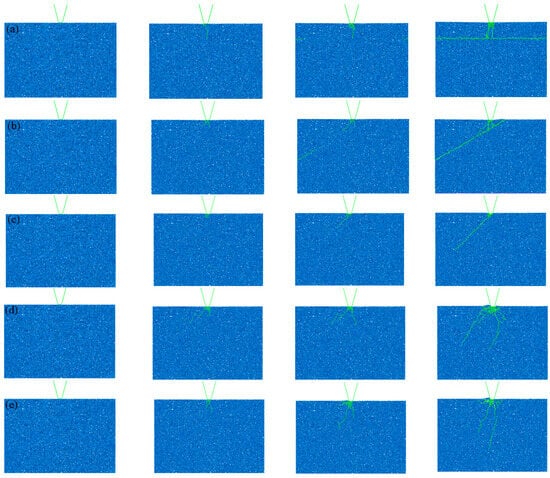
Figure 2.
Law of crack propagation during TBM disc cutter rock breaking under different bedding dip angles. (a) α = 0°; (b) α = 30°; (c) α = 45°; (d) α = 60°; (e) α = 75°.
4.2. Influence of Bedding Spacing on Rock-Breaking Law of TBM Disc Cutter
As shown in Figure 3, the bedding spacing (d, vertical distance between beddings) regulates the rock-breaking effect of TBM disc cutters in a phased manner, and this regulatory role is reflected in the interaction between the cutter-induced “crushed zone” (simulated by the PB model’s bedrock particle cementation failure) and the weak bedding planes (simulated by the SJ model’s sliding characteristics). As shown in Figure 3, when d = 30 mm (relatively dense beddings), a single “branch crack” extending from the “crushed zone” generated at the disc cutter directly propagates along the 45° bedding direction, ultimately causing model failure. When d = 45 mm, due to the increased distance between beddings, after the formation of the “crushed zone”, three “branch cracks” extend from it—among which two “branch cracks” propagate to the two adjacent bedding planes, and one “branch crack” propagates along the disc cutter penetration direction—eventually leading to model failure and reaching the peak number of cracks, corresponding to the optimal rock-breaking efficiency. When d = 60 mm (larger bedding spacing), a “crushed zone” is formed at the disc cutter–bedrock contact surface, and, subsequently, two cracks extending from the “crushed zone” propagate and connect with one bedding plane, resulting in model failure. When d = 75 mm, its crack propagation law is similar to that at d = 60 mm, with the difference that an additional “branch crack” is generated on the left side of the “crushed zone”. When d = 90 mm (sparsely distributed beddings), the beddings are arranged vertically, and the disc cutter does not come into direct contact with the beddings; thus, a large “crushed zone” is generated at the disc cutter–bedrock contact surface, and then a “branch crack” propagates radially along the disc cutter to the deep part of the bedrock, causing model failure. The most valuable result of this analysis is that the bedding spacing of 45° is the optimal spacing for TBM disc cutter rock breaking in stratified rock masses. This spacing enables the “crushed zone” induced by the disc cutter to interact with two adjacent beddings, forming three “branch cracks” that maximize the number of cracks and optimize rock-breaking efficiency, which provides a direct basis for determining the adaptive adjustment range of disc cutter penetration depth and cutterhead operation parameters under different bedding spacing conditions in engineering.
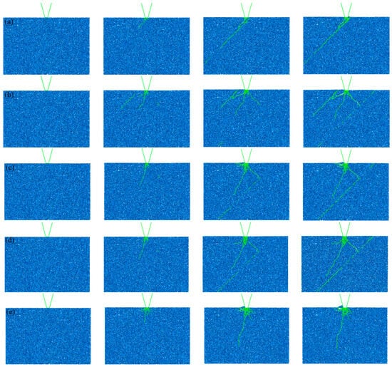
Figure 3.
Law of crack propagation during TBM disc cutter rock breaking under different bedding spacings. (a) d = 30 mm; (b) d = 45 mm; (c) d = 60 mm; (d) d = 75 mm; (e) d = 90 mm.
4.3. Crack–Time Step Curves Under Different Calculation Schemes
Figure 4 displays the crack–time step curves under different calculation schemes. As indicated by the figure, the variation law of cracks with time steps under the action of disc cutter rock breaking exhibits a phased characteristic of “slow initial growth and rapid later surge”. This is highly consistent with the mechanical process of TBM disc cutter rock breaking: in the initial stage (low time steps), when the disc cutter just contacts the rock mass, only local compressive stress is generated at the contact point, which does not reach the bond strength threshold of the rock. Thus, the number of crack initiations is small, and the growth is slow. As the time step increases, the penetration depth of the disc cutter increases, and the accumulated contact stress exceeds the bond strength. A large number of bonds break, and cracks propagate rapidly and penetrate each other, which is manifested as a steep rising segment of the curve. For Scheme A (different bedding dip angles), the number of cracks first decreases and then increases with the increase in bedding dip angle, reaching the minimum when the bedding dip angle α = 45°. This is because, when α = 45°, the apex of the bedding is exactly located at the contact surface between the disc cutter and the bedrock, so the crack propagation is mainly caused by the failure along the bedding plane, and no obvious “crushed zone” is formed. For Scheme B (different bedding spacings), the number of cracks generally first increases and then decreases with the increase in bedding spacing, reaching the maximum when the bedding spacing d = 45 mm. This is because, when the bedding spacing d = 45 mm, the “crushed zone” caused by the disc cutter interacts with the two surrounding beddings, forming three “branch cracks” and intensifying the crushing effect of the bedrock.
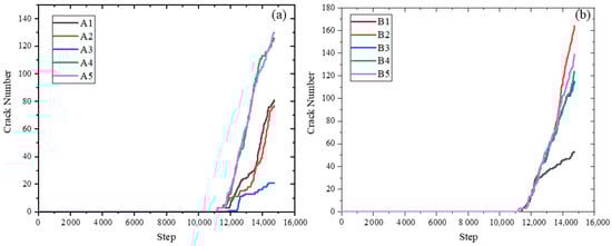
Figure 4.
Crack–time step curves under different calculation schemes. (a) Scheme A; (b) Scheme B.
5. Discussion
5.1. Influence of Bedding Dip Angle on TBM Disc Cutter Rock-Breaking Mechanism
Figure 5 presents the maximum principal stress nephograms of disc cutter rock breaking under different bedding dip angles. As can be observed from the figure, when the bedding dip angle α = 0°, a typical stress concentration zone is formed by the disc cutter loading, which is also the reason for the formation of the “crushed zone”. Meanwhile, the stress concentration zone extends along the disc cutter loading direction, indicating that the subsequently formed “branch cracks” will propagate along the disc cutter loading direction, i.e., across the bedding direction. When the bedding dip angle α = 45°, similar to the case when α = 0°, a typical stress concentration zone is first formed at the contact part between the disc cutter and the bedrock. However, a tensile stress concentration zone is also formed along the bedding direction, which indicates that, after the “crushed zone” is formed, the “branch cracks” will propagate along the bedding direction. When the bedding dip angle α = 75°, the tensile stress concentration is mainly distributed at the bedding close to the disc cutter, indicating that the cracks are mainly damaged along the bedding.
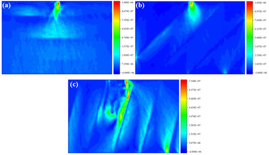
Figure 5.
Maximum principal stress nephograms of disc cutter rock breaking under different bedding dip angles. (a) α = 0°; (b) α = 45°; (c) α = 75°.
5.2. Influence of Bedding Spacing on TBM Disc Cutter Rock-Breaking Mechanism
Figure 6 shows the maximum principal stress nephograms of disc cutter rock breaking under different bedding spacings. When the bedding spacing is small (d = 30 mm and d = 60 mm), a tensile stress concentration zone is formed at the contact part between the disc cutter and the bedrock, resulting in the observed “crushed zone”. Subsequently, a tensile stress concentration area is formed at the bedding, indicating that the “branch cracks” will propagate along the bedding direction. When the bedding spacing is large (d = 90 mm), the tensile stress concentration is concentrated in the vertical direction of the bedrock. This indicates that a large “crushed zone” is generated at the contact between the disc cutter and the bedrock, and then a “branch crack” propagates radially along the disc cutter to the deep part of the bedrock, causing the model to fail.
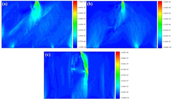
Figure 6.
Maximum principal stress nephograms of disc cutter rock breaking under different bedding spacings. (a) d = 30 mm; (b) d = 60 mm; (c) d = 90 mm.
5.3. Application Prospect of PFC in TBM Disc Cutter Rock-Breaking Simulation
In the field of TBM disc cutter rock-breaking simulation, the Particle Flow Code (PFC) within the discrete element method (DEM) demonstrates significant advantages compared with the finite element method (FEM), especially in accurately depicting the rock-breaking process and revealing the fracture mechanism. The finite element method is based on the assumption of a continuous medium. Although it has high calculation efficiency and is suitable for structural strength analysis, it is difficult to handle discontinuous behaviors, such as large deformation and crack penetration during rock breaking. It is prone to the distortion problem of “excessive breaking under the cutter and insufficient breaking between cutters”, and it has weak ability to characterize the mechanical behavior of weak structural planes in rock masses such as joints and beddings. Moreover, a large number of calibrations are required for the mapping between the material constitutive model and the actual on-site geological conditions, resulting in limited adaptability to complex stratified or joint-developed rock masses. In contrast, PFC takes discrete particles as the basic unit and does not require the preset assumption of a continuous medium. It can naturally describe the entire process of rock from mesoscopic bond breakage to macroscopic crack initiation, propagation, and penetration. Through the combination of the PB model (Parallel Bond) and the SJ model (Smooth Joint), the sliding and separation of bedding planes and the fracture characteristics of jointed rock masses can be accurately reproduced. For example, in this study, the differences in the formation of the “crushed zone” under different bedding dip angles and the law of crack propagation along the bedding were successfully simulated. At the same time, PFC can track the stress transfer path between particles, the number of bond breakages, and the crack propagation direction in real time and intuitively reveal the mechanical mechanism of disc cutter rock breaking. For instance, it clearly shows the inherent reason why cracks can penetrate directly without a large-scale “crushed zone” when the bedding dip angle α = 45°, as well as the mesoscopic mechanism by which bedding spacing affects the number of “branch cracks” and energy consumption. This makes up for the shortcoming that the finite element method has difficulty capturing the mesoscopic failure process and provides a more accurate numerical tool for in-depth understanding of the essence of TBM disc cutter rock breaking and optimization of tunneling parameters.
5.4. Validation of the Numerical Simulation Results
To further verify the reliability of the PFC2D numerical simulation results (based on the discrete element method (DEM) combined with the Parallel Bond (PB) and Smooth Joint (SJ) models) in characterizing the TBM disc cutter rock-breaking process in stratified rock masses, this section compares these results with previous numerical simulations of TBM disc cutter rock breaking using the Smoothed Particle Hydrodynamics (SPH) method [25]. The key focus is on validating the consistency of the core characteristic revealed in this study: the rock-breaking direction along the bedding plane.
Figure 7 presents a comparative analysis of the crack propagation morphology and rock-breaking direction between the PFC2D results (from this study) and the SPH results (from previous research). As shown in Figure 7a (PFC2D results under specific bedding dip angles and spacing conditions in this study), the cracks induced by the disc cutter exhibit an obvious tendency to propagate along the bedding plane: when the bedding intersects the cutter–rock contact point, cracks penetrate directly along the bedding plane without forming an obvious “crushed zone”; when the bedding spacing falls within a specific range, the “crushed zone” interacts with two adjacent beddings. Most of the generated branch cracks extend along the bedding direction, while a small number propagate along the cutter penetration direction—ultimately resulting in rock fragmentation dominated by failure parallel to the bedding. This phenomenon is highly consistent with the SPH simulation results in Figure 7b: under the same bedding conditions in the SPH model, the disc cutter also induces cracks that preferentially propagate along the bedding plane, with no large-scale “crushed zone” formed, and a significant proportion of branch cracks distributed along the bedding direction.
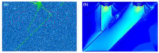
Figure 7.
Comparisons between the PFC numerical results and previous numerical results. (a) PFC results; (b) previous numerical results.
In terms of rock-breaking morphology, both models show that rock chips are mainly “layered blocks” separated along the bedding plane. This is because the bedding, as a weak structural plane, dominates the failure path. The rock-breaking energy of the disc cutter is primarily used to overcome the frictional resistance of the bedding plane (simulated by the SJ model in the PFC2D of this study) rather than crushing the intact bedrock matrix. Even under other typical bedding conditions, the two models remain consistent regarding the rock-breaking direction: the PFC2D results show that branch cracks deflect along the bedding after intersecting with it, while the SPH results exhibit the same deflection behavior, with no obvious difference in the overall trend of rock-breaking direction between the two.
The consistency between the PFC2D and SPH results confirms that the DEM combined with the PB and SJ models can accurately capture the characteristic of “rock-breaking direction dominated by the bedding plane” in stratified rock masses—a key feature that distinguishes rock breaking in stratified rock masses from that in homogeneous rock masses. This validation eliminates potential doubts about the ability of the PFC2D model to simulate discontinuous rock failure, providing a solid foundation for the subsequent analysis of the mechanism by which bedding properties influence disc cutter rock breaking. Additionally, it demonstrates that the core conclusions of this study (e.g., optimal rock-breaking conditions under specific bedding parameters) are not limited to the PFC2D framework but are also supported by another mature numerical method (SPH), further enhancing the credibility and generalizability of the research conclusions.
5.5. Potential Limitations of 2D Simulation (PFC2D) Versus 3D
The primary limitation of the 2D (PFC2D) simulation employed in this study lies in the geometric and mechanical simplifications that deviate from the three-dimensional nature of real stratified rock masses and TBM disc cutter–rock interactions. In the PFC2D model, the disc cutter is simplified as a linear contact element interacting with a two-dimensional rock section, whereas actual TBM disc cutters exhibit surface contact with the rock mass in 3D scenarios. This linear contact simplification alters the stress distribution at the cutter–rock interface: in 2D, compressive and tensile stresses are constrained within a single plane, failing to capture the three-dimensional stress diffusion (e.g., lateral stress propagation perpendicular to the simulation plane) that occurs in real tunneling. For stratified rock masses, the PFC2D model only reproduces bedding planes in the simulation plane (e.g., horizontal or inclined within the 2D space) and cannot account for the spatial variability of bedding orientations (e.g., undulating beddings or cross-beddings) that are common in real geological environments. Consequently, crack propagation in the 2D model is limited to the planar space, preventing the simulation of out-of-plane crack branching or penetration—phenomena that directly affect rock fragmentation efficiency in 3D. For instance, the “three branch cracks” observed at a bedding spacing of 45 mm in the PFC2D model may underestimate the actual number of crack branches in 3D as additional out-of-plane cracks could form under the influence of three-dimensional stress states.
Another critical limitation relates to the generalizability of 2D simulation results to real 3D tunneling engineering. The PFC2D model in this study focuses on the rock-breaking behavior of a single disc cutter or a small cluster of cutters in a planar section, while actual TBM cutterheads feature dozens of disc cutters arranged in a three-dimensional pattern (e.g., spiral or concentric layouts). In 3D, the stress fields induced by adjacent cutters overlap spatially, leading to complex interactions (e.g., stress superposition or stress shadow effects) that regulate crack propagation across the entire rock face. The 2D model, however, can only simulate limited cutter–cutter interactions within the planar space, making it difficult to replicate the collective rock-breaking effect of the entire cutterhead. Additionally, real rock masses exhibit three-dimensional heterogeneity (e.g., random distribution of pores, microcracks, and weak interlayers), which the PFC2D model simplifies to planar heterogeneity. This simplification may lead to discrepancies in crack initiation locations: in 3D, microcracks outside the 2D simulation plane could act as preferential sites for crack nucleation, whereas the 2D model only initiates cracks from pre-defined bedding planes or cutter contact points. While the PFC2D model effectively reveals the intrinsic mechanism of bedding parameters on disc cutter rock breaking, these limitations suggest that its conclusions should be validated by 3D simulations when optimizing TBM parameters for large-scale complex tunneling projects.
6. Conclusions
- (1)
- The bedding dip angle exerts a significant influence on the crack propagation mode and efficiency of TBM disc cutter rock breaking. When the bedding dip angle α = 0°, cracks first form a “crushed zone” and then generate “radial cracks” along the penetration direction. These radial cracks penetrate along the bedding when reaching it and propagate along the horizontal bedding. When α = 45°, the bedding intersects with the contact point of the disc cutter, and cracks penetrate directly along the bedding without an obvious “crushed zone”, resulting in the minimum number of cracks. When α = 60° and 75°, cracks all propagate along the bedding direction. This indicates that the bedding dip angle directly affects rock-breaking energy consumption and rock mass failure morphology by changing the dominant propagation path of cracks.
- (2)
- The regulatory effect of bedding spacing on the rock-breaking effect presents a phased characteristic. When the bedding spacing d = 30 mm, a single branch crack propagates along the bedding to cause rock mass failure. When d = 45 mm, the “crushed zone” interacts with two beddings to form three branch cracks, reaching the peak number of cracks and achieving the optimal rock-breaking effect. When d ≥ 60 mm, with the increase in spacing, the guiding effect of the bedding on cracks weakens. When d = 90 mm, the disc cutter does not contact the bedding, and only a single crack propagating radially is formed, leading to a decrease in rock-breaking efficiency. This confirms that there exists an optimal bedding spacing range to improve rock-breaking efficiency.
- (3)
- The discrete element method (DEM) combined with the PB and SJ models in PFC2D can accurately simulate the entire process of TBM disc cutter rock breaking in stratified rock masses. The PB model can effectively characterize the cementation between bedrock particles and the formation mechanism of the “crushed zone”, while the SJ model can accurately reproduce the mechanical responses of weak structural planes, such as sliding and separation of bedding planes. Additionally, the crack–time step curve with the characteristic of “slow initial growth and rapid later surge” obtained from the simulation is highly consistent with the actual mechanical process of rock breaking, which verifies the reliability of this numerical method in the study of rock-breaking mechanisms of stratified rock masses.
- (4)
- The influence mechanism of bedding properties revealed in this study provides key references for the parameter optimization and engineering application of TBM disc cutter rock breaking. For stratified rock masses with different bedding dip angles and spacings, the disc cutter parameters, such as penetration depth and cutter spacing, can be adjusted to adapt to the crack propagation path: for example, when encountering rock masses with α = 45° bedding, the disc cutter thrust can be reduced to lower energy consumption; when encountering rock masses with bedding spacing around d = 45 mm, the cutterhead rotational speed can be optimized to improve rock-breaking efficiency. This study provides theoretical support for efficient TBM tunneling and cutter design under complex stratified geological conditions.
Author Contributions
L.L., Z.Y., P.L., F.M., Y.Y., R.Z., M.Q., X.T., and S.Y. writing—original draft, writing—review and editing; W.L. and R.M., writing—original draft, writing—review and editing, investigation. All authors have read and agreed to the published version of the manuscript.
Funding
This research is supported by “Opening Foundation of Shandong Engineering Research Center for Mine Gas Disaster Prevention” (No. 2022-006).
Data Availability Statement
The original contributions presented in this study are included in the article. Further inquiries can be directed to the corresponding authors.
Conflicts of Interest
Author Zhili Yang was employed by the Shanxi Huaning Coking Coal Limited Liability Company. The remaining authors declare that the research was conducted in the absence of any commercial or financial relationships that could be construed as a potential conflict of interest.
References
- Wang, X.; Li, J.; Zhao, X.; Liang, Y. Propagation characteristics and prediction of blast-induced vibration on closely spaced rock tunnels. Tunn. Undergr. Space Technol. 2022, 123, 104416. [Google Scholar] [CrossRef]
- Wang, X.; Li, Z.; Li, W.; He, C.; Wang, Z. Analysis and prediction of dynamic stress concentration in jointed coal using boundary element method. Theor. Appl. Fract. Mech. 2025, 140, 105136. [Google Scholar] [CrossRef]
- Xiao, W. Analytical theory on instability sliding of surrounding rock blocks in tunnel roof under stress wave actions. Chin. J. Theor. Appl. Mech. 2024, 56, 183–197. [Google Scholar]
- Wang, X.; Zhang, X.; Li, W.; Jiang, Y.; Li, Z.; Wang, C. Analytical theoretical study on ultra-low friction characteristics of coal rock interfaces under stress wave action. J. China Coal Soc. 2024, 49, 4495–4507. [Google Scholar]
- Liu, P.; Li, S.; Jin, H.; Tian, X.; Liu, G. Shape parameterization method and hydrodynamic noise characteristics of low-noise toroidal propeller. Ocean Eng. 2025, 328, 121088. [Google Scholar] [CrossRef]
- Zhou, X.; Wang, L.; Berto, F.; Zhou, L. Comprehensive study on the crack tip parameters of two types of disc specimens under combined confining pressure and diametric concentrated forces. Theor. Appl. Fract. Mech. 2019, 103, 102317. [Google Scholar] [CrossRef]
- Han, X.; Xiao, Q.; Cui, K.; Lei, S.; Hu, X.; Chen, S. Comparison between some methods for predicting the fracture of hard rock in three-point bending tests. Theor. Appl. Fract. Mech. 2023, 123, 103689. [Google Scholar] [CrossRef]
- Zhang, K.; Xiao, S.; Liu, W.; Wang, D.; Zhang, G.; Sun, J. Analysis of the distributed laser-assisted rock breaking mechanism by TBM disc cutters—Based on microscopic scale scratch tests and macroscopic scale scaled-down disc cutter indenter penetration tests. Eng. Fract. Mech. 2025, 318, 110940. [Google Scholar] [CrossRef]
- Yang, Z.; Tao, M.; Yin, T.; Wu, X.; Xiang, G.; Xu, Y. Microwave-assisted TBM cutter for efficient hard rock fracturing in high stress environments. Eng. Fract. Mech. 2024, 310, 110479. [Google Scholar] [CrossRef]
- Gu, C.; Bao, W.; Zhang, X.; Chen, F.; Jiang, H.; Liu, S. The mechanism of rock-breaking using disc cutter assisted by pre-slotting. Eng. Fract. Mech. 2025, 322, 111165. [Google Scholar] [CrossRef]
- Zhang, K.; Xiao, S.; Liu, W.; Wang, D.; Zhang, G. Feasibility study of an adjustable-power laser cutting head for TBM applications: Focus on rock fragmentation efficiency and energy consumption. Tunn. Undergr. Space Technol. 2025, 155, 106155. [Google Scholar] [CrossRef]
- Qi, W.; Qu, C.; Yan, X.; Kang, Y.; Zhang, Q. Excavation load analysis and efficiency optimization of TBM by multi-disc cutter rotary rock-breaking. KSCE J. Civ. Eng. 2025, 29, 100249. [Google Scholar] [CrossRef]
- Liu, J.; Zhou, Z.; Pan, Y.; Liu, Q. Characterization of particle size distribution of rock chips and evaluation of rock breaking efficiency of TBM based on multifractal theory: A case study. Tunn. Undergr. Space Technol. 2025, 158, 106418. [Google Scholar] [CrossRef]
- Xia, Y.; Guo, B.; Cong, G.; Zhang, X.; Zeng, G. Numerical simulation of rock fragmentation induced by a single TBM disc cutter close to a side free surface. Int. J. Rock Mech. Min. Sci. Géoméch. Abstr. 2017, 91, 40–48. [Google Scholar] [CrossRef]
- Wen, S.; Zhang, C. Experimental and simulation study on rock-breaking efficiency of disc cutters on composite rocks. Int. J. Rock Mech. Min. Sci. Geéomeéch. Abstr. 2022, 153, 105089. [Google Scholar] [CrossRef]
- Hajivand Dastgerdi, R.; Salimi, M.; Wichtmann, T.; Malinowska, A. Peridynamic modeling of rock cutting under a TBM disc cutter using LS-DYNA. Simul. Model. Pract. Theory 2025, 143, 103146. [Google Scholar] [CrossRef]
- Zhang, K.; Liu, Q.; Zhang, Z. Simulation of Rock Breaking Based on FEM-CZM Method and Its Application in Disc Cutter Parameter Optimization. KSCE J. Civ. Eng. 2023, 27, 384–398. [Google Scholar] [CrossRef]
- Cai, C.; Zhang, P.; Xu, D.; Yang, X.; Zhou, Y. Composite rock-breaking of high-pressure CO2 jet & polycrystalline-diamond-compact (PDC) cutter using a coupled SPH/FEM model. Int. J. Min. Sci. Technol. 2022, 32, 1115–1124. [Google Scholar]
- Jiang, H.; Zhang, X.; Liu, S.; Cai, Z. Research on the mechanism and performance of free-surface rock breakage by a disc cutter. Eng. Fract. Mech. 2022, 264, 108336. [Google Scholar] [CrossRef]
- Wang, Z.; Tong, J.; Zhang, X.; Sheng, F.; Gao, Y.; Zheng, K.; Qiu, B. Modeling hard rock breakage behavior influenced by the tipped hob cutter’s tooth structure using the 2D discrete element (DE) model. Powder Technol. 2025, 449, 120361. [Google Scholar] [CrossRef]
- Liu, Z.; Su, S.; Zhao, S.; Zheng, Y. Experimental and numerical study on rock breaking characteristics of TBM disc cutter under coupled static-dynamic loading. Int. J. Rock Mech. Min. Sci. Géoméch. Abstr. 2025, 194, 106248. [Google Scholar] [CrossRef]
- Zhang, B.; Gamage, R.P.; Kong, L.; Zhang, C. Cross-scale proppants transport in the shale hydraulic fracture network: A hybrid CFD-DEM investigation. Eng. Geol. 2025, 354, 108160. [Google Scholar] [CrossRef]
- Dong, Q.; Wang, Y. Investigation of hydraulic fracture propagation patterns and hydro-mechanical coupling mechanisms through DEM analysis. Eng. Anal. Bound. Elem. 2025, 178, 106298. [Google Scholar] [CrossRef]
- Krzaczek, M.; Tejchman, J. Hydraulic fracturing process in rocks—Small-scale simulations with a novel fully coupled DEM/CFD-based thermo-hydro-mechanical approach. Eng. Fract. Mech. 2023, 289, 109424. [Google Scholar] [CrossRef]
- Zhai, S. Rock Fragmentation by TBM Cutters in Deep Complicated Formation; Chongqing University: Chongqing, China, 2017. [Google Scholar]
Disclaimer/Publisher’s Note: The statements, opinions and data contained in all publications are solely those of the individual author(s) and contributor(s) and not of MDPI and/or the editor(s). MDPI and/or the editor(s) disclaim responsibility for any injury to people or property resulting from any ideas, methods, instructions or products referred to in the content. |
© 2025 by the authors. Licensee MDPI, Basel, Switzerland. This article is an open access article distributed under the terms and conditions of the Creative Commons Attribution (CC BY) license (https://creativecommons.org/licenses/by/4.0/).