1. Introduction
As a key measurement and protection device in the power system, the current transformer (CT) bears the important task of transforming the large current on the primary side into measurable secondary current [
1,
2,
3]. Usually, under normal operating conditions, CTs can realize a more ideal linear transformation relationship. However, in special operating conditions with DC components, such as high-voltage DC transmission systems, converter stations, and scenes with severe harmonic interference, CTs are susceptible to DC bias effects, leading to asymmetric magnetization or even saturation of their cores [
4]. This asymmetric flux distorts the output waveform of the CT, which leads to measurement errors and affects the normal operation of the metering and relay protection system [
5,
6,
7].
CT compensation has long relied on physical models and signal processing—e.g., inverse magnetization curves with Jiles–Atherton/Preisach hysteresis, flux estimation via numerical integration, and THD/threshold-based de-saturation—but under strong saturation, remanence, and time-varying burdens, these schemes struggle to balance accuracy and real-time requirements in HV systems where DC bias can stem from HVDC monopolar operation or geomagnetically induced currents [
8,
9]. Model-based pipelines are sensitive to parameter identification and operating-point drift; once the secondary waveform clips, flux-reconstruction errors amplify and erode protection margins. Hardware remedies—such as neutral-point active compensation or dual-stage/wide-linearity cores—mitigate bias yet demand grounding modifications and high retrofit cost, limiting scalability [
10,
11,
12]. Data-driven methods (SVM corrections, shallow ANNs with online scaling, stacked autoencoders with architecture search) report gains mainly in static or lightly dynamic regimes; operating on short windows or static features, they inadequately capture the long temporal dependencies governing saturation onset, recovery, and polarity reversals, reducing dynamic reconstruction accuracy and robustness to distribution shift [
13,
14,
15,
16].
To address these gaps, we propose an LSTM-based inverse reconstruction method for CT saturation compensation under DC bias. Firstly, the current signals with different saturation degrees are extracted as a dataset using PSCAD, and then the dataset is inputted into the LSTM neural network for training to obtain a suitable network structure, and finally several sets of current data with different saturation degrees are selected for simulation. The simulation results show that the method is able to realize the anti-derivative of the distortion current under several saturation degrees with small error, which is of good practicability.
2. Mechanism of the Effect of DC Bias on CT and Saturation Detection
2.1. Formation Mechanism of DC Bias in Power Systems
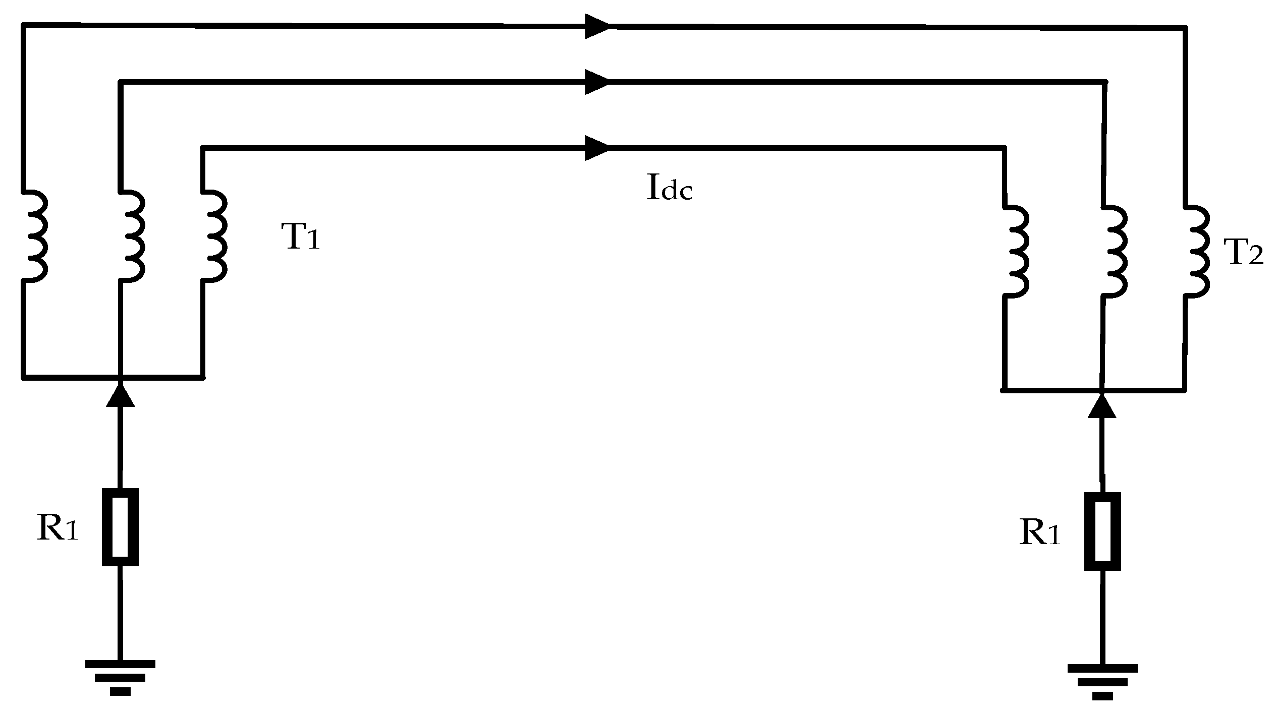
Extensive studies have shown that, when a HVDC transmission system operates in monopolar ground-return mode, the direct current is injected into the earth at one grounding electrode and conducted through the crust to the electrode at the opposite end. Due to significant regional differences in soil resistivity, the neutral points of nearby grounded AC transformers may lie at different electric potentials [
17]. In such a non-uniform potential field, part of the earth current may enter the transformer neutral at a higher potential, flow through its windings and the AC transmission line, and exit via another transformer neutral at a lower potential, thereby forming a closed DC loop [
2]. Previous studies have indicated that this process superimposes a direct-current component onto the primary windings of CTs in the AC network, causing DC magnetic bias. This bias disturbs the magnetic flux balance of CTs and leads to waveform distortion, measurement deviation, and misoperation of protective devices, posing potential risks to the safe and stable operation of the power system [
11,
18].
Figure 1 illustrates the propagation path of this direct current within the AC system. The above findings suggest that the ground-current effect under monopolar HVDC operation essentially arises from potential coupling within multi-point grounding systems under uneven ground potentials. The diffusion of DC components in the AC grid depends on soil resistivity distribution, transmission-line topology, and transformer grounding configuration. Continuous DC accumulation in CT cores drives magnetic saturation and weakens linear response to AC signals. To mitigate these effects, adaptive compensation models based on magnetic-saturation characteristics and local soil conductivity should be developed. Alternatively, DC-blocking reactors or equalizing resistors can be employed to suppress bias. Such measures can reduce the adverse impact of DC magnetization on measurement and protection accuracy, improving both steady-state and dynamic security of AC systems under HVDC ground-return operation.
2.2. Effect of DC Bias on CT Magnetization Characteristics
CT is an electrical device used for AC current measurement. It operates based on the principle of electromagnetic induction, converting high currents into smaller, measurable values for metering and protection purposes [
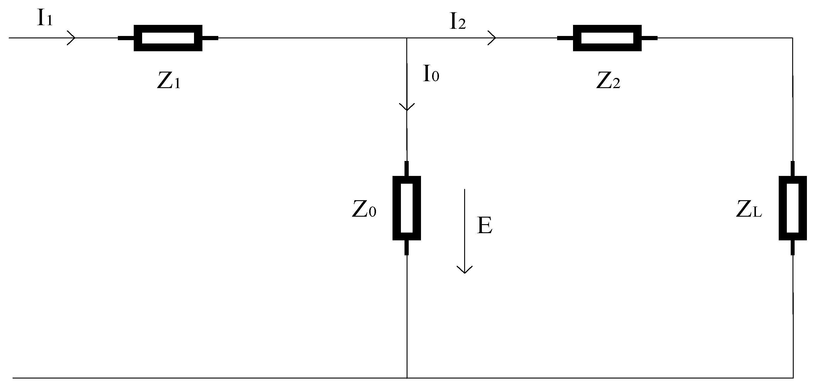
19]. The equivalent circuit is illustrated in
Figure 2, where Z
1, Z
2, and Z
L represent the impedances of the primary winding, secondary winding, and load, respectively. Z
0 denotes the excitation impedance that characterizes the magnetization behavior of the iron core; E is the induced electromotive force across this impedance. I
1, I
2, and I
0 are the primary current, secondary current, and excitation current, respectively, with I
0 producing magnetic flux in the core when flowing through Z
0 [
20]. DC bias in CTs may occur during HVDC operation or geomagnetic disturbances. Under normal conditions, the iron core operates symmetrically, and magnetic flux is balanced between the positive and negative half-cycles. When a DC component is superimposed on the primary current, the flux density shifts, displacing the operating point from zero. The core partially saturates, causing a sharp decrease in permeability. Consequently, the secondary induced electromotive force no longer follows the primary current linearly, leading to waveform distortion characterized by reduced fundamental amplitude and increased harmonic content [
3].
Based on these principles, the essence of CT DC bias lies in the asymmetric magnetization response of the core under the influence of a superimposed DC flux. When the DC component is small and the core remains unsaturated, its effect mainly manifests as a slight offset in excitation current. As the DC component increases and the magnetic flux approaches unidirectional saturation, the CT’s equivalent excitation impedance decreases sharply, weakening the secondary induced voltage. This results in amplified measurement error and delayed protection response.
2.3. Saturation Detection Based on FFT
Under DC bias, the operating point of the CT core shifts and the saturation margin is greatly reduced [
6]. Even small fault currents or aperiodic components can drive the core into deep saturation, resulting in distortion of the secondary current and loss of transfer accuracy. Effective compensation therefore requires a detection method that is real-time, reliable, and computationally efficient. The fast Fourier transform (FFT) provides clear diagnostic features of saturation, including attenuation of the 50 Hz fundamental, enhancement of low-order harmonics such as the second and third, and spectral asymmetry caused by the DC component. It also maintains numerical robustness under moderate noise and achieves sub-cycle latency with low computational complexity. Compared with time-domain flux integration or threshold-based methods [
11], FFT avoids problems of drift and sensitivity to remanence; compared with wavelet or empirical mode decomposition, it achieves similar component separation at lower cost, making it more suitable for online applications.
The FFT is a highly efficient algorithm of the discrete Fourier transform (DFT) [
21], which reduces the computational complexity of the DFT from O(N
2) to O(N·log
2N). This optimization is extremely significant when N is large. The definition of DFT is shown below.
The FFT utilizes the periodicity and symmetry of the exponential terms in the DFT to decompose a large problem into multiple small problems for recursive computation [
22]. Let the input sequence be x[n], the even and odd terms are denoted as x
e[n] = x[2n] and x
o[n] = x[2n + 1], respectively, then we have:
where
is the rotation factor.
From Equation (2), we know that the FFT turns the original problem into two subproblems of length N/2. Continuing the recursion can complete the decomposition quickly.
3. LSTM-Based Saturated-Current Reconstruction and Feasibility Analysis
3.1. LSTM-Based Reconstruction of Saturated Current
3.1.1. Basic Theoretical Analysis of LSTM
The Long Short-Term Memory network is an improved type of recurrent neural network (RNN) designed to model long-term dependencies in time-series data. Its core structure consists of a cell state, forget gate, input gate, and output gate. The cell state runs through the entire sequence and serves as the carrier of long-term memory. The forget gate determines which information should be discarded from the cell state, as defined below.
The input gate controls how new information is written into the cell state, as defined in the following equation.
The output gate decides which information from the cell state is transmitted to the next hidden layer, as defined below.
These operations are governed by nonlinear activation functions such as sigmoid and tanh, which enable selective memory retention and update. Through this gated mechanism, LSTM effectively mitigates the gradient vanishing and exploding problems inherent in traditional RNNs, achieving stable training and strong capability in capturing both short-term transients and long-term dependencies [
23].
Under DC bias conditions, the secondary current of a current transformer (CT) exhibits nonstationary and nonlinear dynamics, characterized by baseline drift, half-cycle asymmetry, saturation onset and recovery, remanence, and waveform clipping. To capture such complex temporal behaviors, a model must retain contextual information across multiple cycles while maintaining robustness during training. Compared with static models such as support vector machines or shallow neural networks that rely on fixed features or short observation windows [
16,
18], the LSTM architecture naturally captures temporal evolution and hysteresis phenomena. It requires shallower receptive fields than convolutional encoders and avoids the drift and parameter sensitivity commonly encountered in flux-integration-based methods. Therefore, the LSTM network provides an appropriate methodological framework for reconstructing CT primary current under DC bias. It aligns well with the physical characteristics of saturation and remanence while ensuring accurate and reliable compensation performance for online applications [
24].
The workflow of LSTM: firstly, the unimportant information in the cell state needs to be discarded through the forgetting gate; then the new information is written into the cell state through the input gate; and finally, the information in the cell state is output into the hidden state through the output gate.
3.1.2. Generation of Dataset and Construction of Model Structure
In this study, the secondary current, converted to the primary side after DC injection, is used as the network input, while the true primary current serves as the reference output. To comprehensively capture the influence of different DC bias levels, a DC component ranging from −50 A to +50 A is superimposed onto the CT neutral point in increments of 0.2 A, producing a total of 501 datasets. This configuration ensures that the training data adequately cover a wide spectrum of magnetic states—from unsaturated to deep saturation—thereby enhancing the model’s representativeness and robustness.
The architecture of the LSTM network has a decisive impact on both its fitting capability and generalization performance. After extensive preliminary experiments, a three-layer stacked LSTM was adopted, with 200 hidden units per layer. This depth and width were found to provide a favorable balance between expressive power and computational efficiency. A smaller number of hidden units would constrain the model’s ability to learn nonlinear magnetic behaviors, while an excessive number could lead to overfitting and degraded stability. To further enhance generalization under varying saturation degrees, a dropout layer with a rate of 20% is inserted between layers to randomly deactivate neurons during training, preventing excessive reliance on specific temporal features.
Model training is performed using the Adam optimizer with a learning rate of 0.0001, which offers an effective compromise between convergence speed and numerical stability. The loss function is mean squared error (MSE), chosen for its sensitivity to amplitude deviations in waveform reconstruction tasks. The entire network is trained for up to 200 epochs with early stopping based on validation performance. The final LSTM configuration, including its structural and training parameters, is summarized in
Table 1.
Also, in order to calculate the error of LSTM for the inverse derivation of CT distortion current under DC bias, the following definition is introduced:
where I
2 is the RMS value of the primary side current of the CT and I
0 is the RMS value of the LSTM compensation current.
3.2. Feasibility Analysis
To evaluate the online applicability of the proposed model, we analyze the inference computational cost and latency of a three-layer LSTM. The multiply–accumulate operations (MACs) required per LSTM time step can be approximated as
where H and I are the hidden and input dimensions. For our stack, the total is approximately equal to 0.803 MMACs per sample (approximately equal to 1.606 MFLOPs). Under 8 kHz sampling, true streaming therefore needs a sustained throughput of
For 50-Hz systems, a 20-ms (160-sample) and a 40-ms (320-sample) window require approximately 257 million and 514 million floating-point operations, respectively. On an FP32 CPU delivering at least 100 gigaflops per second, the corresponding single-thread latencies are about 2.6 ms and 5.1 ms, leaving ample headroom for a sub-cycle update rate of twenty ms or less.
4. Back-Estimation Process Based on LSTM
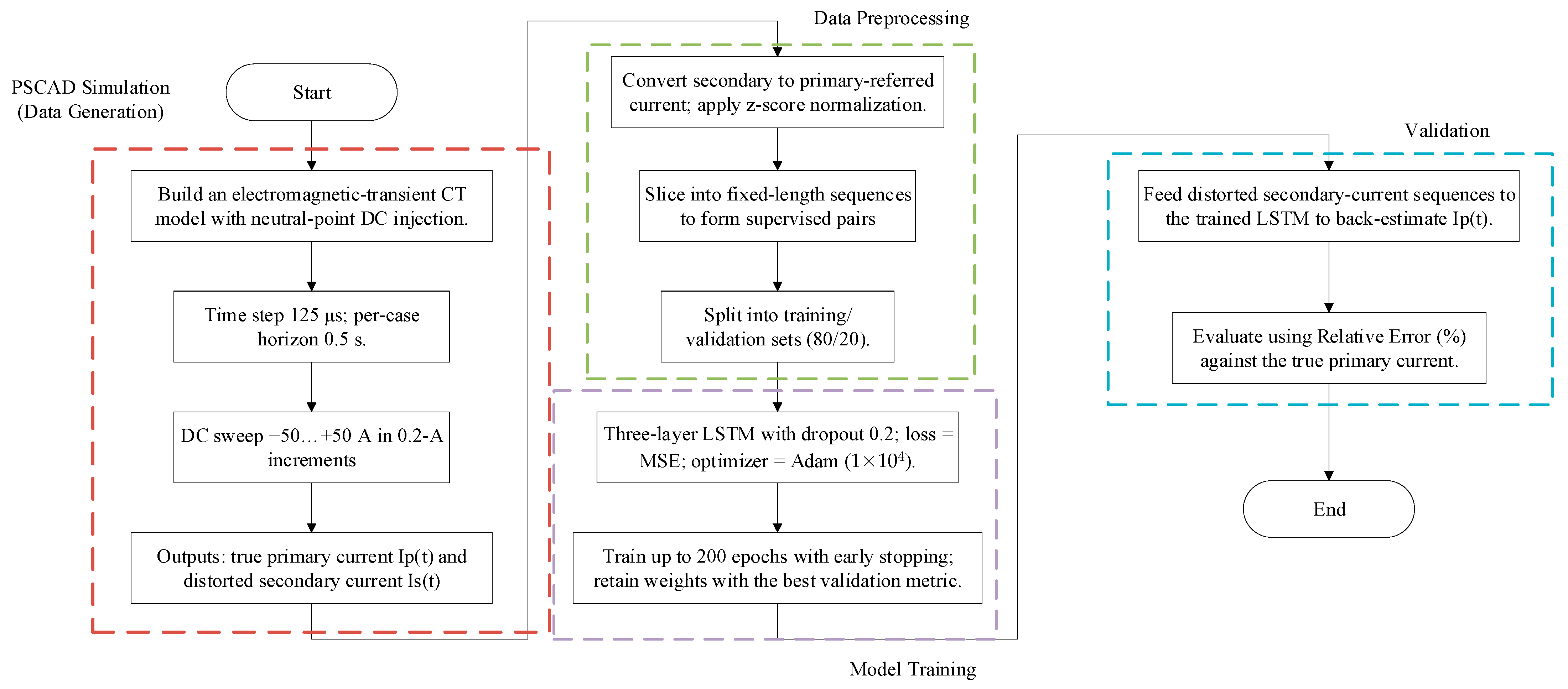
To accurately back-estimate the distorted secondary current of a current transformer under DC bias conditions, a complete back-estimation process based on the LSTM neural network is designed in this study. The process mainly consists of four steps: data generation, data preprocessing, model training and validation, and model inversion and output. The schematic is shown in
Figure 3.
- 1.
Data Generation
An electromagnetic transient model with a DC bias source was established in the PSCAD platform. DC components of varying amplitudes were injected into the transformer neutral to obtain both the true primary current and the distorted secondary current of the CT. To capture fast flux excursions and waveform clipping during saturation while maintaining stability and efficiency, the simulation step was set to 125 μs, corresponding to a 4 kHz Nyquist that covers saturation-induced harmonics. Each case was simulated for 0.5 s to include both the DC-driven transition into saturation and the subsequent quasi-steady state. The injected DC was swept from −50 A to +50 A in 0.2 A steps (501 points), ensuring that the dataset spans a wide range of distortion patterns.
- 2.
Data Preprocessing
The simulated current data are normalized to have a mean of zero and a standard deviation of one, which improves training convergence speed and model stability. Meanwhile, the secondary-side current, converted to the primary side, is used as the input sequence for the model, and the true primary current serves as the output sequence, forming supervised learning sample pairs. All samples are then divided into a training set (80%) and a validation set (20%) for subsequent model training and testing.
- 3.
Model Training and Validation
During the training phase, the model weights are iteratively updated over multiple epochs using the training set, with the maximum number of epochs set to 200. The decline trend of the loss function and the validation set error are closely monitored. After each epoch, the model is evaluated on the validation set to prevent overfitting. Training is terminated early and the optimal model parameters are saved when the validation error converges or shows no significant improvement over several consecutive epochs.
- 4.
Model Inversion and Output
The trained LSTM model is applied to the distorted secondary current inputs from the test set to estimate the corresponding primary-side current values. To evaluate the model’s performance, the relative error metric is used to compare the estimated values with the true values. The final back-estimated current can be used for dynamic restoration of the CT primary current, effectively compensating for saturation distortions caused by DC bias.
5. Simulation Validation and Results Analysis
5.1. Analysis of the Effects of DC Polarization on CTs
PSCAD is a powerful piece of electromagnetic transient simulation software for power systems, which can simulate the dynamic response of the system at the microsecond level in detail, and is suitable for studying transient processes [
25]. In this paper, the simulation model shown in
Figure 4 is built in the PSCAD simulation platform. In this model, the DC power supply is connected to the neutral point of the transformer, which is used to simulate the injection of DC components into the system. The AC power supply frequency is 50 Hz, and the AC source impedance is (1.2 + j1.6) Ω. The simulation step size is set to 125 μs, and the simulation time is set to 0.5 s. The current transformer of the J-A model that comes with PSCAD is used, and the parameters of the CT are shown in
Table 2.
5.2. Saturation Detection
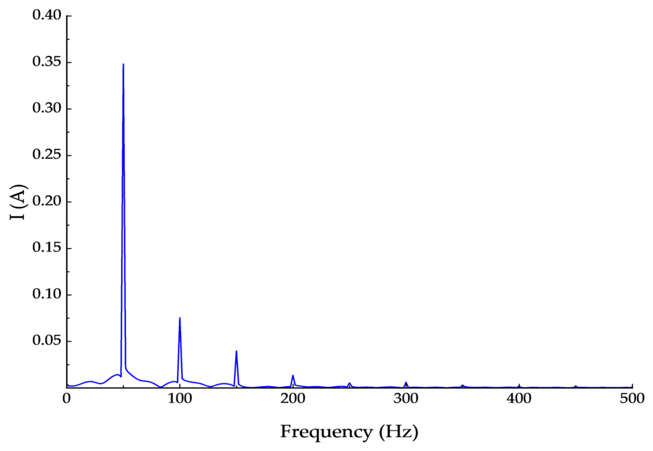
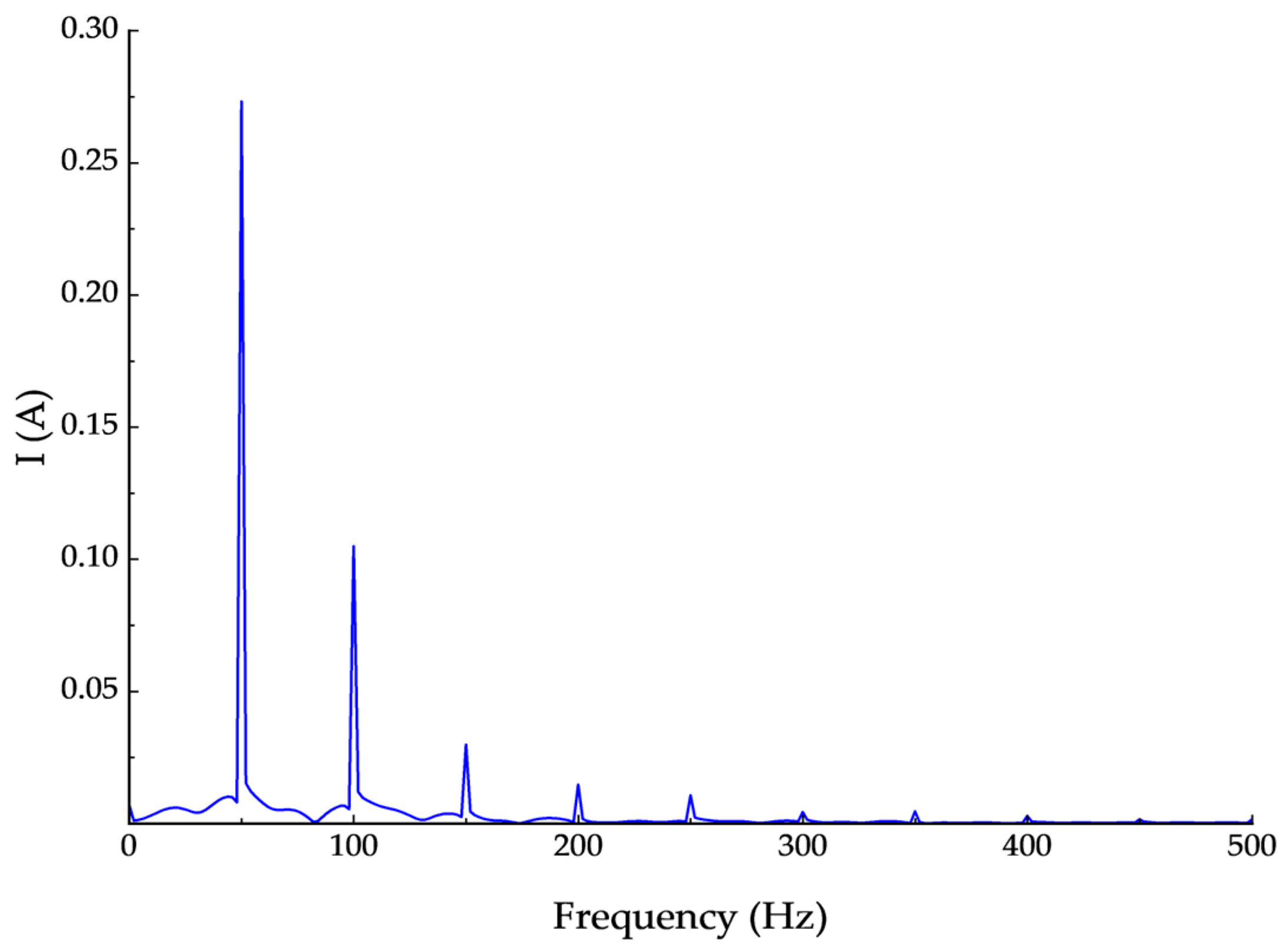
The saturation level of the CT is shown in
Figure 5,
Figure 6 and
Figure 7 when the injected DC components are 10 A, 30 A and 50 A, respectively.
Figure 5,
Figure 6 and
Figure 7 show that, as the DC bias increases from 10 A to 30 A and 50 A, the spectral characteristics of the CT secondary current change markedly, reflecting a progressive increase in saturation. At 10 A, the spectrum is dominated by the 50 Hz fundamental with high amplitude, indicating that the CT is essentially unsaturated. At 30 A, the fundamental decreases while distinct harmonics, especially near 100 Hz and 150 Hz, become evident, signifying the onset of saturation. At 50 A, the fundamental is further attenuated, the harmonic content grows significantly, and distortion components are greatly enhanced, indicating severe saturation and degraded measurement performance. Overall, a larger DC component results in deeper CT saturation, stronger nonlinear distortion, and increased harmonic content in the spectrum.
5.3. Evaluation Protocol and Metrics
This work trains a three-layer unidirectional LSTM (200 hidden units per layer) with 20% inter-layer dropout and a step-wise linear readout on z-score-normalized 8 kHz inputs, using MSE loss and Adam (learning rate 1 × 10
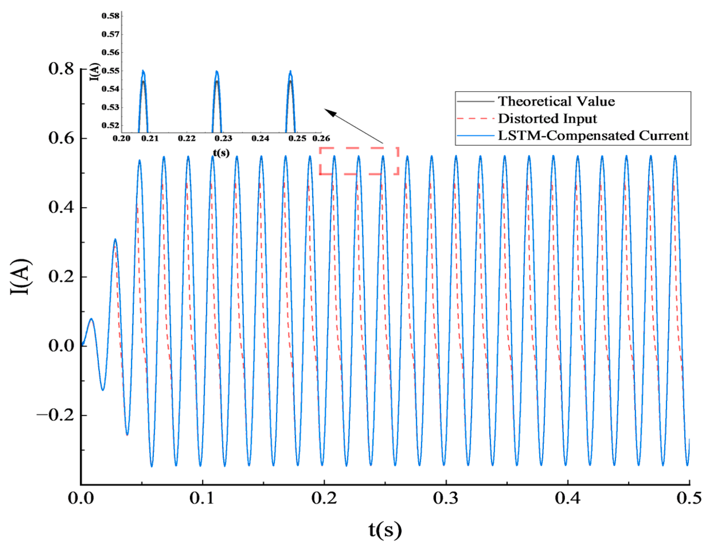
−4, batch size 64) for up to 200 epochs with early stopping. Reconstruction results for the 36.6 A DC-bias case are shown in
Figure 8.
Figure 8 illustrates the distortion of the input signal. The red dashed line shows the secondary current distorted by DC bias (referred to the primary side), which is asymmetric between positive and negative half-cycles and exhibits unequal peaks and valleys, indicating partial saturation. This waveform reflects typical distortion under DC bias. The blue curve represents the LSTM output, which almost completely overlaps with the theoretical primary current (black line). Despite an initial transient, the model maintains accurate dynamic fitting, and after about the 500th sample point, the two waveforms are nearly synchronized. The high degree of overlap demonstrates strong temporal modeling and tracking capability. According to Equation (9), the error in this case is only 0.66%, confirming the model’s practicality and accuracy under moderate saturation.
To verify the adaptability and robustness of the proposed LSTM-based current back-estimation method under different DC bias conditions, this study selects 10 representative sets of DC component amplitudes, covering typical scenarios from severe negative bias (−45.2 A) to severe positive bias (+47.2 A). Back-estimation simulations and error evaluations were performed for each current waveform set [
26], with the results shown in
Table 3.
Table 3 shows that the back-estimation errors for all cases remain within 2%, with a minimum of 0.06% and a maximum of 1.26%. These results demonstrate that the LSTM model maintains high accuracy and adaptability across different saturation levels and polarities. The error distribution is stable for both positive and negative DC bias, indicating no systematic overestimation or underestimation and confirming strong symmetric modeling capability. As the injected DC amplitude increases, the errors do not show a clear upward trend; in fact, some moderate cases yield extremely low values of 0.07% and 0.76%. This further verifies the model’s ability to reconstruct primary current features across diverse saturation conditions. Given that CT measurement errors in power systems are typically controlled within ±5%, and the proposed method consistently performs within ±2%, the approach provides accurate compensation of distorted waveforms without hardware modifications and shows strong potential for engineering application.
5.4. Noise Sensitivity Analysis
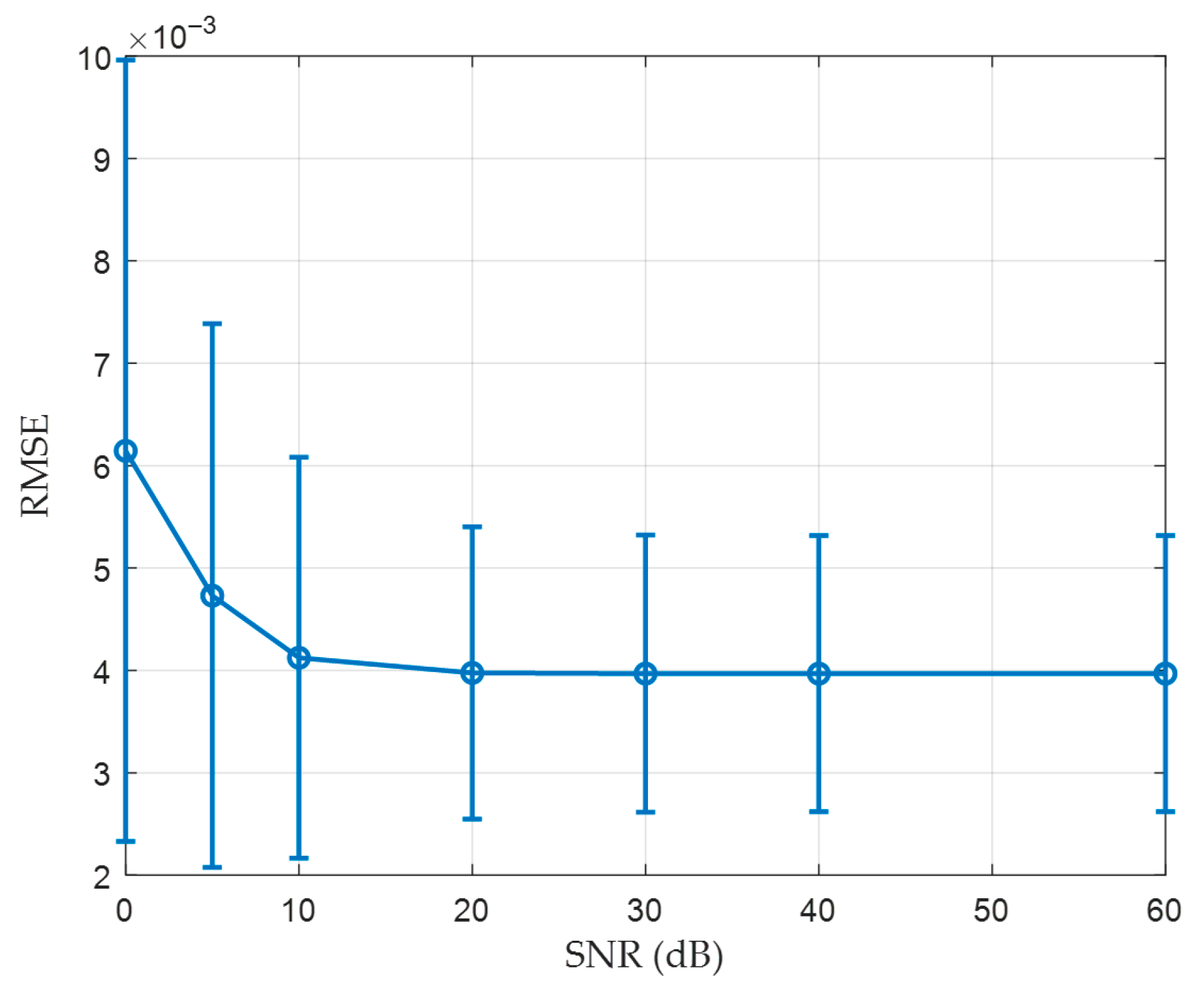
To assess the robustness of the proposed LSTM back estimator under measurement noise, additive white Gaussian noise was injected into the secondary-side input only, while the primary-side ground truth remained clean. The signal to noise ratio in decibels was computed with respect to the input signal power. The network was trained on clean data and evaluated without retraining so that the results reflect intrinsic robustness rather than the effect of data augmentation. Error metrics were root mean square error and mean absolute error; both computed against the clean primary current. Evaluations were performed at signal to noise ratios of 0, 5, 10, 20, 30, 40, and 60 decibels. For each level, all test waveforms were processed and the mean and the standard deviation across files were reported as error bars.
Figure 9 and
Figure 10 show that the reconstruction accuracy improves steadily with increasing signal-to-noise ratio (SNR), and both error curves flatten above approximately 20 dB. At low SNRs (0–5 dB), errors and variability rise sharply due to severe signal corruption, while at higher SNRs the performance stabilizes near a low-error plateau, indicating reliable reconstruction under typical noise levels. The relatively wide error bars below 20 dB further reveal case-to-case differences caused by random phase and amplitude perturbations, which can shift the timing of core saturation and remanence recovery within each waveform. As SNR increases, the temporal features captured by the LSTM network dominate over stochastic noise, causing these variations to contract and the results to converge toward a stable plateau. Overall, the observed fluctuations reflect the inherent randomness of strong noise rather than model weakness, confirming that the proposed LSTM back-estimation method remains robust under realistic operating conditions.
5.5. Results of Model Comparison
To evaluate the effectiveness of the proposed LSTM-based reconstruction model, two representative methods—a Support Vector Machine (SVM) and a shallow feedforward Artificial Neural Network (ANN)—were selected for comparison [
15,
16]. All models were trained and tested using identical data splits, normalization statistics, and an early-stopping policy to ensure fairness.
As shown in
Table 4, the LSTM model achieves the best performance among the three. Its RMSE is 0.001146, representing reductions of 66.29% and 79.54% compared with SVM (0.0034) and ANN (0.0056), respectively. The MAE is 0.000894, showing decreases of 44.12% and 72.06% relative to SVM and ANN. These results indicate that the LSTM effectively reconstructs the primary current waveform with higher accuracy and stability under DC bias conditions.
The superior performance of the LSTM model arises from its ability to capture long-term temporal dependencies and nonlinear hysteresis effects in the magnetization process of CTs. Unlike static models that rely on short input windows or fixed features, the LSTM dynamically models transient and steady-state behaviors, maintaining accuracy across varying saturation levels. Therefore, the proposed method demonstrates strong robustness and reliability for online DC bias compensation in protection and metering systems.
6. Conclusions
In this paper, for the problem of waveform distortion on the secondary side of CT caused by DC bias magnetization, an inverse diffraction method of LSTM neural network is proposed to recover the real current waveform under the distortion condition, and the following conclusions are obtained:
In terms of simulation modeling, a high-fidelity electromagnetic transient simulation model containing a transformer, a CT and a DC bias source is constructed with the help of the PSCAD platform; the saturation distortion response of a CT with different amplitude DC components is successfully simulated; and abundant training samples are obtained.
In terms of model construction, a deep learning LSTM-based inverse diffraction network is designed for the temporal characteristics of current sequences.
The experimental results show that the LSTM network is able to restore the original current waveforms more accurately in a typical DC bias field scene, and the error is generally below 2%.
The proposed LSTM-based back-estimation of secondary distorted current delivers lower RMSE and MAE and better amplitude consistency than the baselines under DC bias and saturation, and remains robust to input white noise, with errors stabilizing at or above 20 dB, and a negligible impact in typical 30 to 40 dB conditions, demonstrating engineering readiness for online compensation in protection and metering chains.
Current validation is simulation-based and uses PSCAD models. Field trials should assess generalization to varying core materials, burdens, and remanence histories; domain adaptation or few-shot fine-tuning can mitigate distribution shifts. Hardware-in-the-loop evaluation and fail-safe logic for extreme clipping should also be added before utility deployment.
Author Contributions
Conceptualization, Z.R., K.Y., G.C., Y.Y., Y.C. and L.Z.; methodology, Z.R., K.Y., G.C., Y.Y., Y.C. and L.Z.; software, Z.R., K.Y., G.C., Y.Y., Y.C. and L.Z.; validation, Z.R., K.Y., G.C., Y.Y., Y.C. and L.Z.; writing—original draft preparation, Z.R., K.Y., G.C., Y.Y., Y.C. and L.Z. All authors have read and agreed to the published version of the manuscript.
Funding
This research received no external funding.
Data Availability Statement
The original contributions presented in this study are included in the article. Further inquiries can be directed to the corresponding author.
Conflicts of Interest
Authors Zhanyi Ren, Kanyuan Yu, Guangbo Chen, Yunxiao Yang were employed by the company Yangjiang Nuclear Power Co., Ltd. The remaining authors declare that the research was conducted in the absence of any commercial or financial relationships that could be construed as a potential conflict of interest.
References
- Zhang, Z.; Chen, B.; Wu, Y. Study on anti-dc characteristics of magnetic valve current transformer. Electr. Power Autom. Equip. 2022, 42, 129–135. [Google Scholar]
- Zhang, D.; Yang, L.; Xiao, Y. Transmission characteristics of wide-range current transformer based on zero flux principle. South. Power Syst. Technol. 2024, 18, 150–158. [Google Scholar]
- Yin, S.; Xiao, G.; Xiao, Y. Detailed explanation of the reason why current transformer secondary conductor parallel winding to realize fractional-turn compensation will produce negative compensation. Transformer 2015, 52, 16–18. [Google Scholar]
- Lu, S.; Yang, S.; Cai, J. Study on the mechanism of DC bias on current transformer. Electr. Meas. Instrum. 2014, 51, 6–11. [Google Scholar]
- Huang, T.; Li, Z.; Huang, Q. Calculation method and characterization of error under DC bias of low-voltage current transformer for metering. Power Syst. Technol. 2025, 49, 373–380. [Google Scholar]
- Ma, S.; Xia, S.; Xiong, W. Differential analysis of HVDC/GIC-type DC bias. Power Syst. Prot. Control 2023, 51, 55–64. [Google Scholar]
- Yan, Q.; Li, S.; Ye, Y. Characterization of current transformer measurement under DC bias. Electr. Meas. Instrum. 2021, 58, 144–148. [Google Scholar]
- Hu, C.; Zhang, Z.; Chen, G. Research on online compensation technology of current transformer for metering under DC bias. Instrum. Tech. Sens. 2021, 4, 40–44. [Google Scholar]
- Yuan, J.; Sun, G.; Zhu, D. Analysis of saturation characteristics of current transformer and its compensation. Electr. Meas. Instrum. 2012, 49 (Suppl. S1), 165–169+176. [Google Scholar]
- Zhou, S.; Xu, Z.; Liu, B. An all-fiber current transformer error compensation method based on improved BP neural network. Jiangxi Electr. Power 2024, 48, 1–5+42. [Google Scholar]
- Li, J.; Huang, J.; Zhang, Y. DC compensation method for suppressing transformer saturation due to DC bias. Sci. Technol. Eng. 2021, 21, 3618–3625. [Google Scholar]
- Hu, H.L.; Xu, Y.; Wu, X.; Lin, F.; Xiao, X.; Lei, M. Passive-compensation clamp-on two-stage current transformer for online calibration. IET Sci. Meas. Technol. 2021, 15, 730–737. [Google Scholar] [CrossRef]
- Odinaev, I.; Abdel-Aty, A.-H.; Pazderin, A.; Safaraliev, M.; Matrenin, P.; Senyuk, M.; Menaem, A.A.; Kanan, M. Restoration of the current transformer secondary current under core saturation conditions based on ANN. Heliyon 2024, 10, e37960. [Google Scholar] [CrossRef]
- Key, S.; Sok, V.; Lee, S.-W.; Ko, C.-S.; Nam, S.-R.; Lee, N.-H. Current Transformer Saturation Compensation Based on Autoencoder and Deep Learning. In Proceedings of the 2020 IEEE Power & Energy Society General Meeting (PESGM 2020), Montreal, QC, Canada, 2–6 August 2020; Institute of Electrical and Electronics Engineers: New York, NY, USA, 2020; Volume 5, pp. 3259–3263. [Google Scholar]
- Liu, J.; Pei, J.; Tian, M. Research on nonlinear correction method of current transformer based on support vector machine. Electr. Mach. Control 2020, 24, 130–138. [Google Scholar]
- Musyoka, E.M.; Chang, C.-K. ANN Based Model for Current Transformers’ Saturation Error Compensation in Medium Voltage Switchgears. J. Electr. Eng. Technol. 2022, 17, 2171–2179. [Google Scholar] [CrossRef]
- Zhang, L.; Mao, C.; Sun, L.; Han, Y.H.; Han, Q. Review of Research Status on DC Magnetic Bias of Transformers. Electrotech. Electric 2019, 8, 1–6. [Google Scholar] [CrossRef]
- Sun, Y.; Zhang, L.; Zhang, Z.; Wang, D. Overview of research status of DC bias and its suppression in power transformers. Energies 2022, 15, 8842. [Google Scholar] [CrossRef]
- Dang, S.; Xiao, Y.; Wang, B.; Zhang, D.; Zhang, B.; Hu, S.; Song, H.; Xu, C.; Cai, Y. A High-Precision Error Calibration Technique for Current Transformers under the Influence of DC Bias. Energies 2023, 16, 7917. [Google Scholar] [CrossRef]
- Wang, L.; Zeng, W.; Tian, J. Effects of DC component and harmonic component on the transmission characteristics of current transformers. Electr. Mach. Control 2023, 27, 1–8. [Google Scholar]
- Convertini, V.N.; Impedovo, D.; Lopez, U.; Pirlo, G.; Sterlicchio, G. Discrete Fourier Transform in Unmasking Deepfake Images: A Comparative Study of StyleGAN Creations. Information 2024, 15, 711. [Google Scholar] [CrossRef]
- Liu, Q.; Xu, X.; Lu, Z.; Yu, L.; Jiang, D. Weak signal extraction of micro-motor rotor unbalance based on all-phase fast Fourier transform. Int. J. Mech. Syst. Dyn. 2024, 4, 202–212. [Google Scholar] [CrossRef]
- Alhamd, Q.; Saniei, M.; Seifossadat, S.G.; Mashhour, E. Advanced Fault Detection in Power Transformers Using Improved Wavelet Analysis and LSTM Networks Considering Current Transformer Saturation and Uncertainties. Algorithms 2024, 17, 397. [Google Scholar] [CrossRef]
- Atiyah, A.W.; Karimi, S.; Moradi, M. Real-Time Revolutionizing Internal Defect Detection in Power Transformers by Leveraging Wavelet Transform and Deep Learning LSTM in Cascading Application. J. Electr. Eng. Technol. 2024, 19, 1–20. [Google Scholar] [CrossRef]
- Hu, H.; Chenhui, C.; Pengyu, Y.; Yujie, D.; Xiao, Z. Current transformer saturation detection and distortion current compensation. J. Northwest Univ. (Nat. Sci. Ed.) 2022, 52, 52–59. [Google Scholar]
- Zhang, W.; Xu, L.; Chen, X.; Guo, P.; Li, H.; Zhu, C. Study on error-measurement methods for transformer bushing current transformers. Transformer 2020, 57, 7–11. [Google Scholar]
| Disclaimer/Publisher’s Note: The statements, opinions and data contained in all publications are solely those of the individual author(s) and contributor(s) and not of MDPI and/or the editor(s). MDPI and/or the editor(s) disclaim responsibility for any injury to people or property resulting from any ideas, methods, instructions or products referred to in the content. |
© 2025 by the authors. Licensee MDPI, Basel, Switzerland. This article is an open access article distributed under the terms and conditions of the Creative Commons Attribution (CC BY) license (https://creativecommons.org/licenses/by/4.0/).
