Abstract
Aiming to address the challenges of determining the coal pillar’s width and managing the significant deformation of the surrounding rock in the deep gob-side entry driving, the limiting equilibrium zone theory, employing the operational area of Dongpang Mine 21110 as the engineering setting, states that a coal pillar’s appropriate width in the gob-side entry driving falls between 7.9 and 9.8 m. The pattern of vertical stress distribution and the extent of the plastic zone in the roadway for coal pillar widths of 7.0 m, 8.0 m, 9.0 m, and 10.0 m are analyzed, respectively, investigated using the numerical simulation method of FLAC3D. The acceptable coal pillar width in the deep gob-side entry driving is 8.0 m. Combined with the roadway surrounding rock borehole inspection results, the fracture development condition of the roadway’s full-face surrounding rock is determined, and the asymmetric aberration characteristics, with significant surrounding rock damage depth at the coal pillar flank location, are obtained. Based on the theoretical calculations, an integrated proposal for a “non-symmetrical bolt and cable anchor” coupling support scheme for the surrounding rock in the gob-side entry driving is put forward. This was applied at the Dongpang coal mine site. Engineering practice shows that leaving an 8.0 m coal pillar width and adopting the “non-symmetrical bolt and cable anchor” support system design can control the deformation of the surrounding rock in the track entry at a reasonable range, which ensures the stability of the surrounding rock in the gob-side entry driving.
1. Introduction
With the increase in global mineral consumption, shallow coal and mineral resources are gradually being depleted, and underground mining is continuously developing towards deeper levels. The rapid depletion of shallow resources in China is causing coal mines to extend more deeply at a rate of 8 to 25 m per year. Deep mining is developing in the direction of full automation, intelligence, and mechanization. The exploitation of deep mines brings a series of problems. China’s coal industry faces significant challenges due to the need to enhance efficiency and promote green, sustainable development [1,2,3,4,5].
Huang et al. [6], by creating a 3D model and conducting sampling experiments, found that the coal pillar width is directly proportional to the working face’s length. Du et al. [7], by summarizing the stress distribution patterns in the coal pillars under the roadway, concluded that the stress in the surrounding rock will shift cyclically during the mining stage. Chen [8] used limit equilibrium theory to establish a method for calculating the appropriate width of a coal pillar to control roof and rock deformation. Jiang [9] builds a model to study an inclined coal seam. The second invariant curve of the off-stress field depends on the coal pillar width. Xu et al. [10] studied the stress distribution law to determine the width of the coal pillar. This approach to controlling the effect on the roof and surrounding rock reached its target. Kang et al. [11] studied the stability laws for deep soft rock roadways from the perspectives of theory, technology, methods, and engineering practice, and this guided the on-site application of surrounding rock control in coal mine roadways. Jiang et al. [12] simulated the percentage of the plasticity degree of a coal pillar in goaf excavation, reflecting the transfer of deviatoric stress between solid coal and coal pillar, and proposed a joint support to control the surrounding rock deformation. Wang et al. [13] examined the deviatoric stress in coal pillars of varying widths in soft broken coal in a gob-side entry driving. Wang et al. [14] investigated mining’s impact on roadway deformation. Findings show that coal pillar width impacts disturbance. Meng et al. [15] reported that the elastic core area in a narrow coal pillar was proportional to the width of the pillar and that a pillar width of 4 m was effective for maintenance. Chen et al. [16] studied vertical stress and the potential for roof and floor failure in relation to varying coal pillar widths using FLAC3D. They determined the optimal spacing of anchor rods for roadway support, which saved on support costs and increased coal utilization efficiency. Huang et al. [17] established a mechanical model for small coal pillar dual roadway mining and proposed that a narrow coal pillar can not only improve coal utilization, but also be used for ventilation mechanisms for excavation and mining. Zhang et al. [18] determined that a coal pillar of 5 m in width could mitigate mining pressure and reduce surrounding rock movement. This aligns with safety requirements. Zhu et al. [19] built a roadway model and investigated heave causes. They also proposed an anchor bolt and cable support technique. Liu et al. [20] investigated the damage mechanism of proximal coal seams for goaf on the roadway. The findings showed the need to improve surrounding rock support in gob-side entry driving, in order to make the roadway safer. He et al. [21] used multiple methods to analyze the rock dynamic characteristics in deep coal mining, enriching the theory and methods of deep coal mining technology. Ma et al. [22] created a mechanism to assess the stress distribution of coal pillars. The results showed that the width of a coal pillar can control the amount of deformation of the roadway’s surrounding rock. Jawed et al. [23] analyzed the size and shape of coal pillars, studied the relationship between pillar width and roadway stability, and proposed a mechanism for better stability of a diamond shaped coal pillar. Chang et al. [24] studied the relationship between lateral support stress and coal pillar width in the control technology of the surrounding rock of the side roadway in the goaf. Xu et al. [25] used high prestressing anchor cables to support the roof and rib in order to solve problems relating to the deformation and damage of the roadway caused by the vertical stress of the coal pillar in proximal coal seams. Wang et al. [26] explored the determination of the protective coal pillar width in accordance with the damage patterns of the main roof. Ghasemi et al. [27] found that supporting loads in a room and pillar coal mine may lead to accidents during the mining process. Therefore, they proposed determining the size of the active mining zone (AMZ) to calculate the coal pillar load. Wei [28] investigated the impact of coal seam inclination on the stability of coal pillar. This involved establishing a plastic softening model to predict the width of the inelastic zone. Yin et al. [29] explored the mine pressure characteristics in the context of irregularity in deep goaf, dense coal seams and roadways under residual coal pillars. The surrounding rock presented a challenge, which required control. A program for this control was proposed.
The article first analyzes the mine pressure manifestation characteristics of the 21110 working face roadway in the Dongpang Mine. Theoretical calculations, numerical simulations, engineering analogies, and other methods are used to refine the analysis of the stress distribution for the reserved coal pillar, changes in the stress on the surrounding rock in the plastic zone, and the lateral support pressure distribution on the mining face. The study investigates the stability of the surrounding rock at coal pillars of different widths, obtains the destruction range of the roadway’s surrounding rock, and comprehensively proposes a “non-symmetrical bolt and cable anchor” combined support scheme. The scheme has been successfully applied in engineering practice. The findings contribute to a theoretical framework for determining the coal pillar width and the surrounding rock in gob-side entry driving and provides a technical reference.
2. Engineering Overview
2.1. Geological Profile
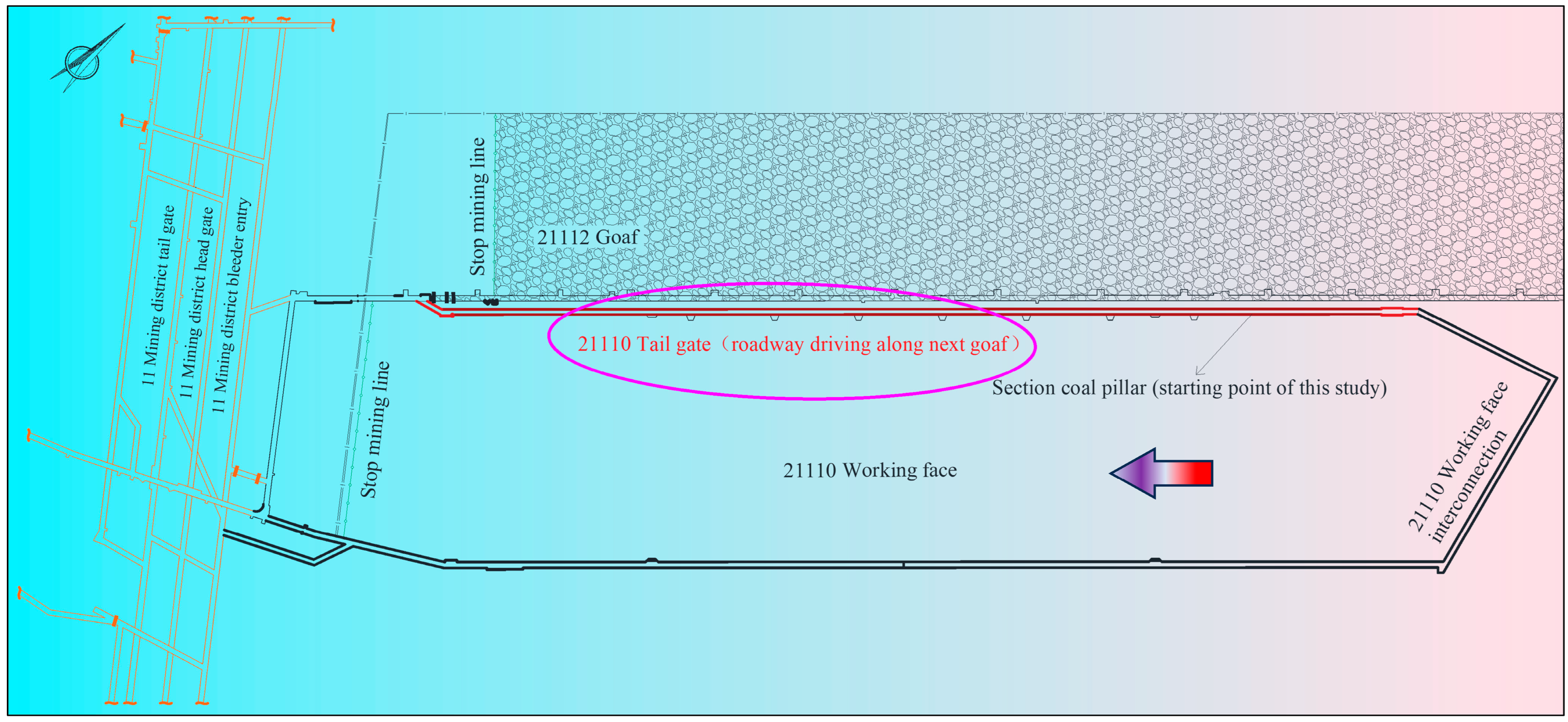
The 21110 working face of Dongpang Mine is located on the left wing of the 11 mining area at the deep level, adjacent to the 21112 goaf in the northwest, adjacent to the waterproof coal pillar in the upper disc of the DF108 Fault and F14 Fault in the northeast, and adjacent to the 21112 material yards in the southwest, as shown in Figure 1. The 21110 working face, with a strike length of 215 m, is mined at an elevation ranging from −490 to −550 m. The trackway of the 21110 working face is arranged parallel to the trackway of 21112.
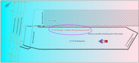
Figure 1.
21110 Working face layout.
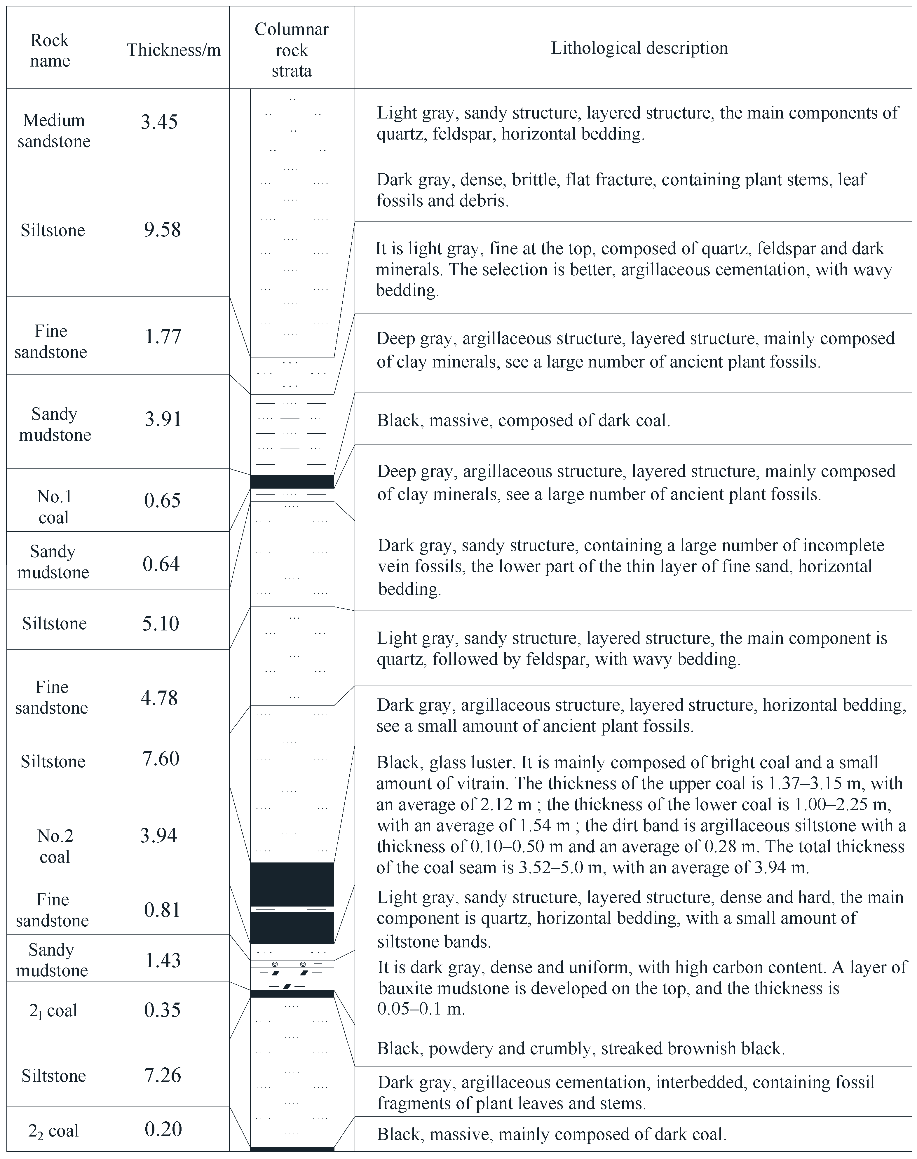
The No. 2 coal seam above the 21110 working face ranges in thickness from 1.37 to 3.15 m, averaging 2.12 m. The lower coal seam ranges in thickness from 1.00 to 2.25 m, averaging 1.54 m. The interlayer, which is argillaceous siltstone, ranges in thickness from 0.10 to 0.50 m, averaging 0.28 m. The coal seam is 3.52 to 5.0 m thick, averaging 3.94 m. The dip angle of the coal seam ranges from 1° to 8°, and the strike of the coal seam ranges from 231° to 53°. The columnar diagram of the rock mass is shown in Figure 2.
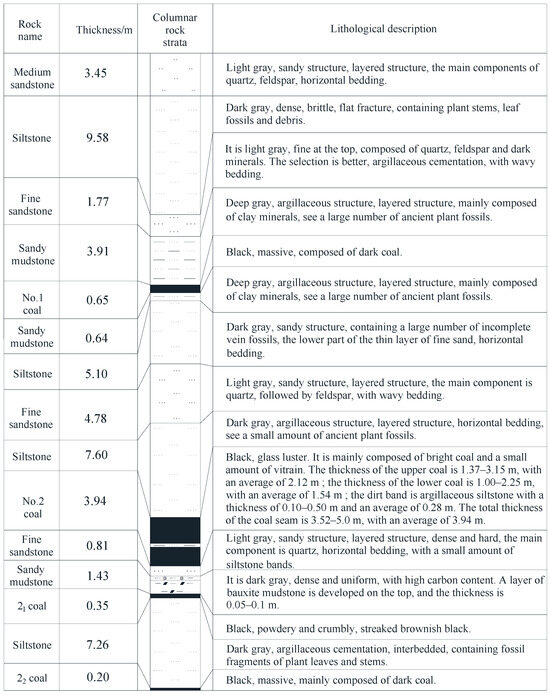
Figure 2.
Columnar diagram of the rock mass.
2.2. Characteristics of Mineral Pressure Manifestation
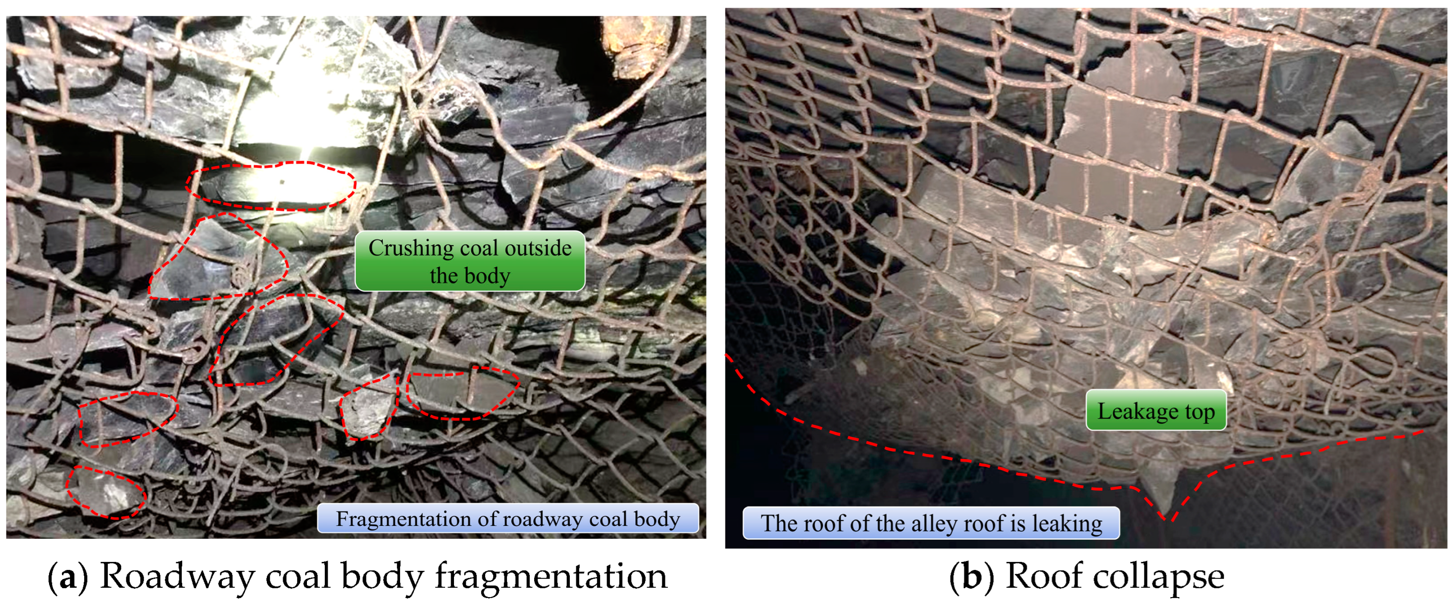
21110 working face within the No. 2 coal seam deposition is characterized by greater stability, the structure is complex and consists of strata, and there is a large variation in coal seam thickness. The working face area’s geological structure is complicated, mainly in fracture structure, and the coal mining roadway is predominantly impacted by the faults. According to the revelation of the 21110 return airway and the 21112 belt haulage way, it is predicted that the development of faults in the outer and middle sections of the working face will destroy the continuous integrity of the coal and rock layer, which will bring certain difficulties to the stability of the coal entry surrounding rock. The retreat mining process for the No. 2 coal 21110 working face near the broken coal body is shown in Figure 3a, mainly manifested in the rib net pocket fracture and the broken coal downward accumulation, a dropsy outward phenomenon; roof collapse occurs, as shown in Figure 3b.

Figure 3.
21110 Working face coal roadway destruction.
The No. 2 coal seam is damaged by large deformation around the roadway under the action of fault stress and 21112 mining goaf. For the purpose of ensuring normal mining at the 21110 working face, a section of coal pillar along the gob-side entry driving between 21110 and 21112 working faces is selected to be retained as the test area of the roadway.
3. Theoretical Calculation of Reasonable Coal Pillar Width
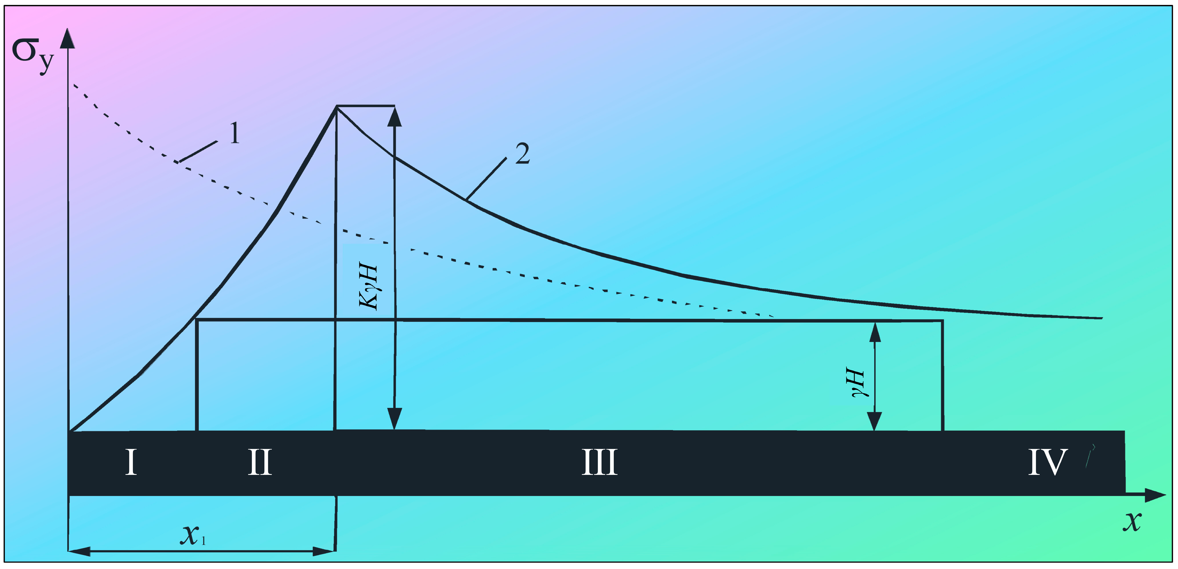
Retaining coal pillar is a commonly used safety measure in coal mining, aimed at establishing a buffer zone between different areas of the mine to reduce the impact of rock stress on the mine structure. To safeguard the roadway, a defined coal pillar width is maintained between the upper section’s head entry and the lower district tail entry, mainly to protect the tail entry in the lower section from the direct influence of the fixed support pressure peak zone in the upper section. The coal pillar’s load-bearing capacity rises as the distance from its edge increases, given that the edge experiences higher rock stress compared to the central region, where the rock stress is comparatively lower. At a segment at the coal pillar’s edge, limit equilibrium may be reached in bearing capacity and supporting pressure, as shown in Figure 4.
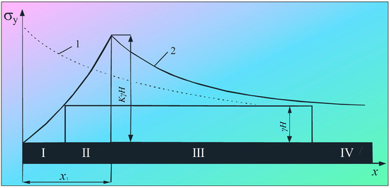
Figure 4.
Elastic–plastic deformation zone and vertical stress distribution of coal pillar. 1—Elastic stress distribution; 2—Elastic–plastic stress distribution; I—Fracture zone; II—Plastic zone; III—Increased stress in the elastic zone; IV—Stress Zone of original rock.
The plastic zone width x1 is the distance between the support pressure peak and the coal wall in accordance with the limit equilibrium theory of rock masses, and can be determined by the Formula (1):
In the formula, x1 represents the width of the plastic zone formed by the coal mass on the goaf side following the extraction of the upper section working face, m; m is the thickness of the coal seam mining, 3.94 m; K is the stress concentration factor, taken as 1.2; f is the friction coefficient of the contact surface between the coal seam and the roof and floor, taken as 0.3; is the triaxial stress coefficient, , and the friction angle inside the coal body is φ = 31°, be ; is the average bulk density of the rock layer, 24 kg/m3; C is the cohesion of coal, 2 MPa; H is the seam depth of the working face, 617.5 m; and P1 is the resistance of the support body to the coal wall, 3.7 MPa.
Substituting the above data into (1), x1 = 4.9 m, a reasonable width for the coal pillar in gob-side entry driving:
In the formula, x2 denotes the effective and reasonable length of the bolt within the coal pillar, taken as 1.6 m; and x3 is the coal pillar safety factor that needs to be considered for the coal-seam thickness. Due to the mining of a medium thick coal seam, x3 is taken as 20~50% of (x1 + x2) [30], with x3 = 1.3~3.3 m.
Based on the above conditions, calculate and substitute in (2) to obtain B = 7.8~9.8 m, which means that the reasonable theoretically calculated coal pillar width is 7.8~9.8 m.
4. Numerical Simulation of Reasonable Coal Pillar Width
4.1. Numerical Model Establishment and Simulation Scheme
To ascertain the rational width for the coal pillar, this numerical simulation is conducted in accordance with the production geological conditions of the 21110 working face in the Dongpang coal mine. Using FLAC3D numerical simulation software, a numerical model with dimensions of X × Y × Z = 100 m × 50 m × 24.3 m is established. The model runs along the X-axis as the direction of the working face, the Y-axis direction as the inclination of the working face, and the Z-axis as the vertical direction.
The boundary conditions of the model include a lateral constraint on horizontal movement and a bottom constraint on vertical movement, and a vertical load of 14.83 MPa is applied to the roof, the self-weight of the overlying 593.2 m thick rock layer is simulated, and the lateral pressure coefficient is set to 1.2. The Mohr–Coulomb constitutive model is used for the studied rock layer. Simulations conduct analyses of stress distribution and plastic zone development in coal pillars of varying widths, specifically 7 m, 8 m, 9 m, and 10 m. The mechanical parameters of various rock masses are shown in Table 1.

Table 1.
Rock mass mechanical parameters.
4.2. Simulation Results Analysis
4.2.1. Vertical Stress Distribution Law for Different Coal Pillar Widths
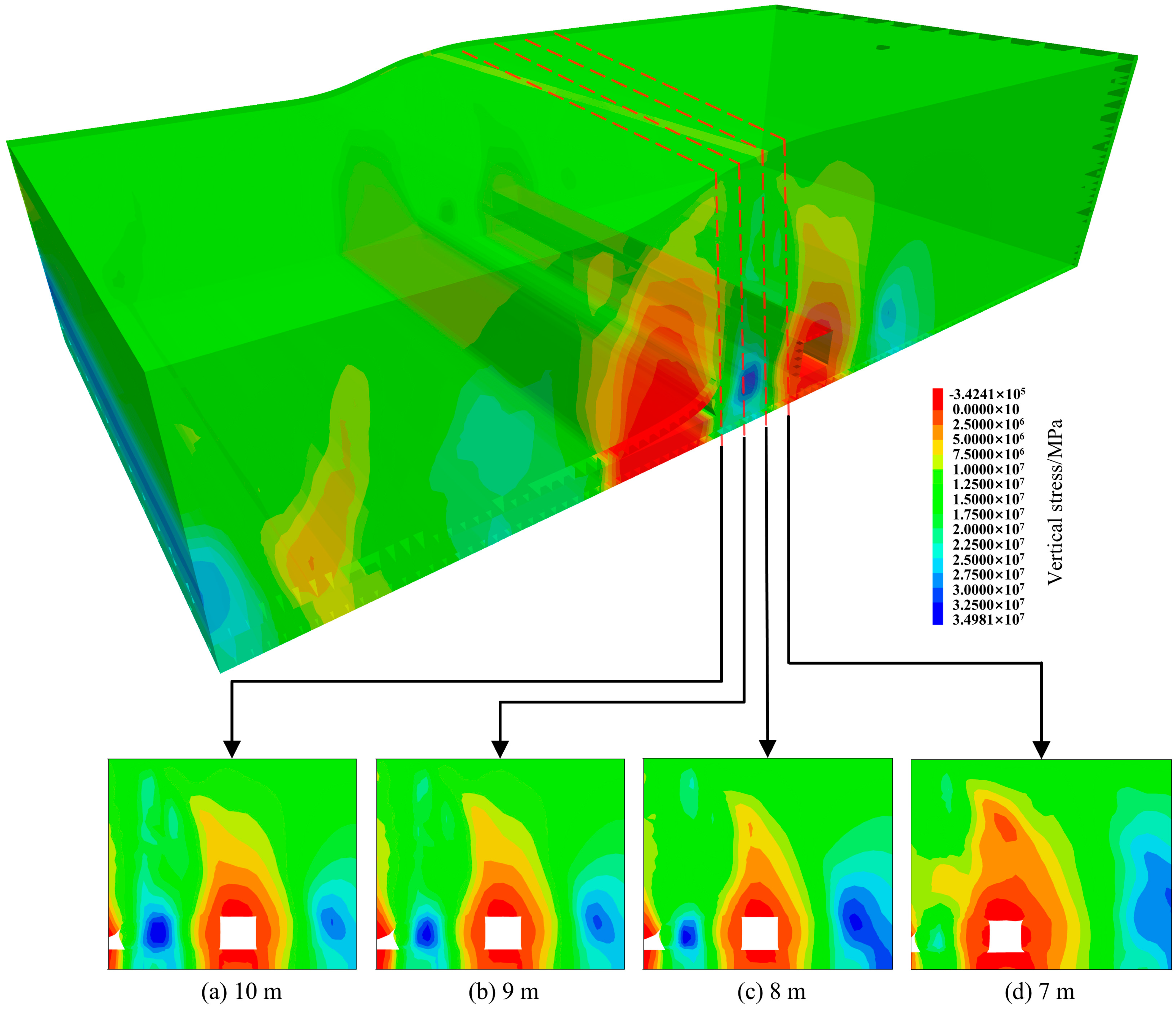
The vertical stress distribution cloud map of the surrounding rock of the roadway under different coal pillar widths is shown in Figure 5.

Figure 5.
Cloud map of vertical stress distribution in the surrounding rock of the roadway under different coal pillar widths.
- (1)
- As the 21110 working face is mined, the surrounding rock of the roof and floor experiences deformation, breaking the equilibrium state of the in situ stress field in the coal measures and causing the rock stress field to be redistributed during mining. To reach the equilibrium state again, a lateral support stress is formed on the coal pillar side.
- (2)
- Stress concentration occurs in the gob-side entry driving. With the progressive widening of the coal pillar, the area of stress concentration transitions from the solid coal pillar to the coal pillar. Consequently, the coal pillar experiences greater vertical stress compared to the solid coal pillar.
- (3)
- When the coal pillar width is 7 m, the stress experienced is less than that experienced by the solid coal pillar. The primary concentration of support stress is concentrated in the solid coal pillar. There is no high stress zone inside the coal pillar, resulting in poor load-bearing capacity and difficult maintenance of the roadway; As the coal pillar is widened to 8 m, the stress is transferred to it, forming stress-bearing areas. This mitigates stress concentration in solid coal. At this point, the roadway possesses strong control capabilities, facilitating the stabilization of the surrounding rock.
- (4)
- As the width of the coal pillar continues to increase to 9~10 m, the supporting stress and stress range of the coal pillar rapidly increases. The coal pillar endures a peak stress that surpasses the stress in the solid coal pillar. This results in stress concentration within the coal pillar, which is detrimental to the management of the roadway’s surrounding rock.
The arrangement of stress observation lines along the gob-side entry driving the 21110 working face to monitor and extract data, and the drawing of vertical stress distribution maps of the coal pillar according to different coal pillar widths, is shown in Figure 6.
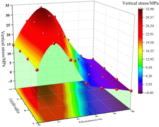
Figure 6.
Vertical stress distribution diagram under different coal pillar widths.
As illustrated in Figure 6, as the distance from the 21110 working face along the gob-side entry driving is increased, the vertical stress hump shape of the coal pillar is distributed, and the peak position is not at the center of the coal pillar but biased towards the roadway about 2 m away from the coal pillar side. As the coal pillar width increases, the peak value of the vertical stress on the coal pillar also rises gradually. Upon reaching a width of 7 m, the peak stress value is just 26.4 MPa. As the coal pillar’s width expands to 8 m, the maximum stress rises to 28.3 MPa, with a 1.07-fold increase in maximum stress. When the coal pillar width reaches 9 m, the peak stress increases to 31.7 MPa, but the this equals 1.12 times; when the pillar’s width extends to 10 m, the peak stress rises to 32.9 MPa, with a minor fluctuation in peak stress at around 32 MPa. However, at this width the coal pillar is already in a high stress concentration zone.
Based on the comprehensive theoretical calculation and numerical simulation regarding the coal pillar width in the gob-side entry driving, in order to keep the coal pillar’s vertical stress at a low level, a reasonable width for the coal pillar should be around 8 m.
4.2.2. Distribution Pattern of Plastic Zone with Different Coal Pillar Widths
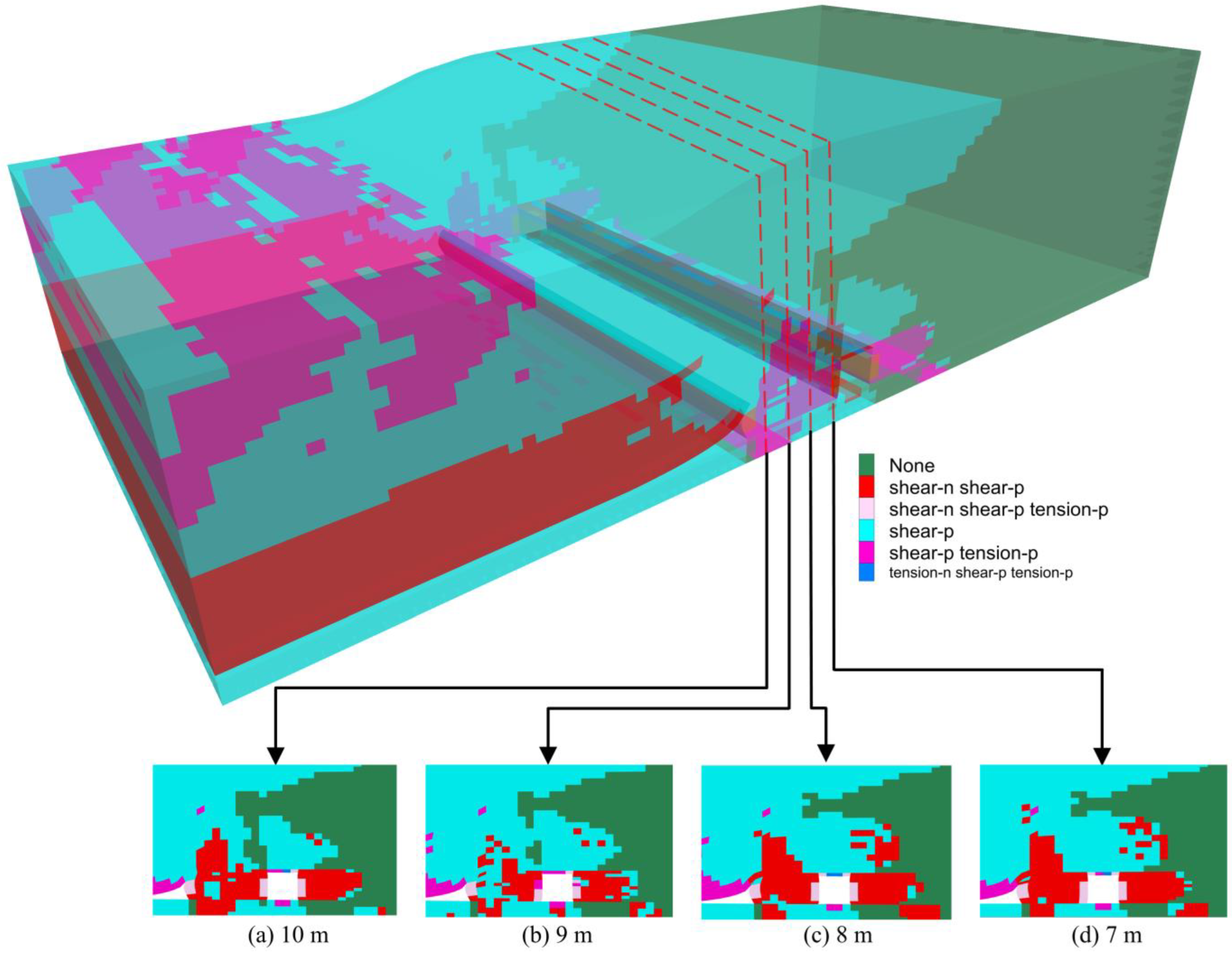
The distribution pattern of plastic zones under different coal pillar widths is shown in Figure 7.

Figure 7.
Cloud map of plastic zone distribution under different widths of coal pillar.
Under the influence of the 21110 goaf, the plastic zone of the roadway surrounding rock is subjected mainly to shear failure, with a small number of areas experiencing tensile failure. At a coal pillar width of 7~8 m, the failure mode shows an “H-shaped” symmetrical distribution along the two sides of the roadway. As it increases, it shows an approximately “inverted T-shaped” distribution characteristic at 9~10 m; at a coal pillar width of 7 m, relatively high damage to the surrounding rock and the degree of compression on the roadway are more obvious, and this is obviously insufficient to support the stability of the roadway; at a coal pillar width of 8 m, the plastic zone of the local coal pillar changes, and its stress is transferred to the surrounding rock floor. There are areas inside the coal pillar that have not been damaged, and the coal pillar may be stable; the coal pillar is 9~10 m wide and the plastic zone of the surrounding rock is discontinuous, but shear failure is dominant. While a wider coal pillar might make the road safer, it would waste coal.
4.3. Determination of Coal Pillar Width
In the analysis based on Table 2, it can be concluded that the width of the coal pillar is related to the vertical stress in the surrounding rock and the degree of plastic zone failure. Thus, it is determined that a reasonable width for the coal pillar is 8 m.
Table 2.
Comparison of different coal pillar widths.
5. Support Parameters and Schemes for Gob-Side Entry Driving
The cross-section of the 21110 working face roadway is 4.5 m × 3.5 m. Through numerical simulation, a reasonable width for the coal pillar is 8 m. Rock deformation, plastic zone distribution, and stress distribution determine the coal pillar’s stability. Therefore, controlling the surrounding rock deformation is essential. According to the geological conditions of Dongpang Mine production, a support scheme of the “non-symmetrical bolt and cable anchor” type is proposed for gob-side entry driving.
5.1. Borehole Observation of Surrounding Rock in Gob-Side Entry Driving
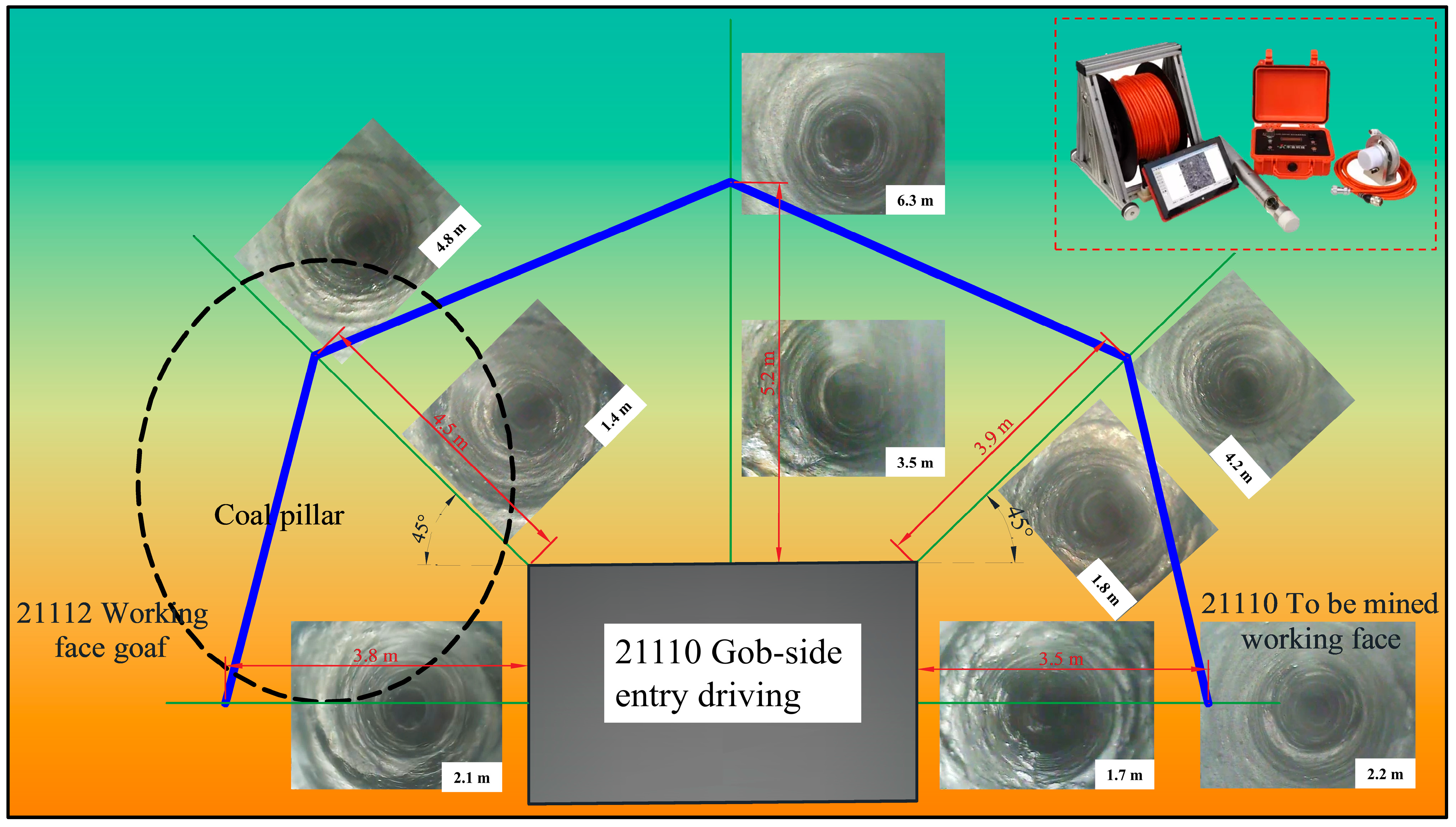
Based on the observation of the surrounding rock of the 21110 track roadway gob-side entry driving, the characteristics of deformation and failure in the roadway at different positions are studied; five drilling observation positions are arranged in the sector area above the 21110 track roadway, located directly above the vertical roof, at the left and right shoulder angles of the roof (with a 45° angle to the roadway roof), on the side of the coal pillar adjacent to the 21112 working face’s mining area, and on the side of the solid coal adjacent to the 21110 working face. Figure 8 shows the borehole observation results.
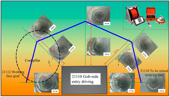
Figure 8.
Borehole observation diagram of 21110 track roadway.
Figure 8 shows that within the sector area, 2.1 m away from the mining coal pillar, 1.4 m from the left shoulder corner, 3.5 m from the roadway roof, 1.8 m from the right shoulder corner, and 1.7 m from the solid coal pillar, there are transverse and longitudinal fractures and some fragmentation in the surrounding rock. The surrounding rock on the outer side of the roadway break line is relatively intact and there are no large fractures. Therefore, the inside failure line is the key area for track roadway support. It is proposed that the extent of the anchor cable on the left shoulder corner of the trackway and the roof should not be less than 4.5 m and 5.2 m, respectively.
5.2. Design of Support Parameters for Surrounding Rock in Gob-Side Entry Driving
5.2.1. Verification of Support Parameters Based on the Unit Anchor Cable Suspension Principle
- (1)
- Roof bolts through the suspension action, and rib bolts through the reinforcement of the rib body, to achieve the condition of support effect, should meet:
In the formula:
—Total length of anchor bolt, mm;
—The exposed length of the anchor bolt is taken as 100 mm;
—Thickness of soft rock layer, (roof bolt free arch height , rib bolt taken coal rib breakage depth );
—Anchor bolt penetration depth into competent rock; take ;
In the calculation formula for mining pressure in the deep mining roadway, when both sides of the roadway are damaged, the calculation formula for the pressure arch is:
In the formula:
—Half span of the heading roadway is taken as 2.25 m;
—Roadway height, taking 3.5 m;
—The internal friction angle of coal is recalculation based on Proctor’s consolidation coefficient, taking 31°;
—Roof rock mass internal friction angle, which is a recalculation based on Proctor’s consolidation coefficient, taking 36°;
Calculated according to the above formula: ; roof bolt length ; rib bolt length .
- (2)
- Verification of anchor bolt spacing based on the weight that the anchor bolt can suspend
Roof bolt anchoring force: calculated based on the yield load of the bolt body
In the formula:
—The yield strength of anchor rod material, taken as ;
—Anchor rod diameter, taken as ;
Roof bolt spacing:
In the formula:
—The number of roof bolts per row, taken as 6;
—The safety factor range is 2~3, with 3 taken here;
—The bulk density of the roof rock mass, taken as 24 kg/m3;
—Verification calculation for the selected roof bolts:
According to the above formula, it is calculated so that ; roof bolt spacing ; bolt spacing .
5.2.2. Calculation Based on the Natural Pressure Arch Principle
The parameters of the natural equilibrium arch are calculated using the loose body theory method, according to the calculation of parameters when both sides of the roadway are damaged in the deep mining roadway pressure calculation formula. List Proctor’s formula as follows:
Potential caving arch height ; squeezing damage depth of the coal body on both sides .
Rib side pressure value :
In the formula:
—Half span of the heading roadway, taken as 2.25 m;
—The bulk density of roof strata in the roadway, taken at 24 kg/m3.
- (1)
- Roof bolt parameters
- 1.
- Roof bolt length:
- 2.
- Anchorage length:
- 3.
- Bolt spacing:
In the formula:
—The roof bolt hole diameter is taken as 33 mm;
—The resin adhesive bonding strength with rock is taken 40 kg/cm2;
- (2)
- Rib bolt parameters
- Rib bolt length:
In the formula:—Anchorage length is taken as 659 mm;—The rib bolt hole diameter is taken as 29 mm;—The resin adhesive bonding strength with rock is taken as 20 kg/cm2;- 2.
- Bolt spacing:
In the formula:—The number of ribs per row is taken as 10;—The anchor rod anchoring force is taken as 12 t;—The rib bolt spacing is 1 m;
According to the above formula, it is calculated that the roof bolt length , the rib bolt length ; roof bolt spacing , bolt spacing ; rib bolt spacing , row spacing , and the selected anchor bolt parameters in construction can meet the calculation requirements. The design of the 4.5 m (width) × 3.5 m (height) roadway uses a roof and rib bolt with a length of 2400 mm, and the spacing between the roof and rib bolt is 800 mm × 800 mm. The parameters of the anchor bolts selected for construction can meet the calculation requirements.
5.3. Optimization Scheme for Gob-Side Entry Driving Support
- (1)
- Roof support. Roof bolts: Each row of the roadway roof is lined with six equally robust, fully threaded steel rock bolts, each measuring 22 mm × 2400 mm, equipped with S2360 and Z2360 resin cartridges. The full-length anchoring force is a minimum of 15 t, while the torque is a minimum of 300 N·m. The arrangement of roof bolts in rows should have a spacing of 800 mm × 800 mm on the vertical roof plane.
Roof cable anchors: Using 17.8 mm × 8500 mm steel strand anchor cable and configuring one roll of S2360 resin cartridge and three rolls of Z2360 resin cartridge, with a pre-tension force of not less than 130 kN, two rows of No. 12 channel steel are arranged in step-by-step cross-chaining along the roadway, with each row 1 m away from the center of the roadway, and the spacing between the rows is 2 m × 2.4 m.
- (2)
- Rib support. Rib bolts: On either side of the roadway, there are 10 completely threaded 20 mm × 2400 mm HRB335 steel rock bolts, each fitted with a roll of S2360 and a Z2360 resin cartridge, ensuring a minimum anchoring force of 12 tons and torque of 250 N·m; the distance between each rib bolt measures 800 mm × 800 mm.
Rib cable anchors: Adopting a 15.24 mm × 4500 mm steel strand and assembling one roll of S2360 resin cartridge and two rolls of Z2360 resin cartridge, with a pre-tension force not less than 100 kN, two rows of channel steel cable bolts are arranged along the roadway, at a distance of 2.4 m. The distance from the top of the cable bolts to the roof should not exceed 1.5 m, and 3 m long No. 12 channel steel is used for all channels.
A proposal for a “non-symmetrical bolt and cable anchor” support system for gob-side entry driving, as depicted in Figure 9, emerges from rock borehole peeping findings, the design of anchor bolt and cable support parameters, and the geological dynamics of Dongpang Mine production.
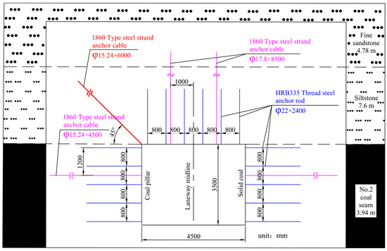
Figure 9.
Roadway cross-section support diagram.
6. On Site Mining Pressure Observation and Control Effect Analysis
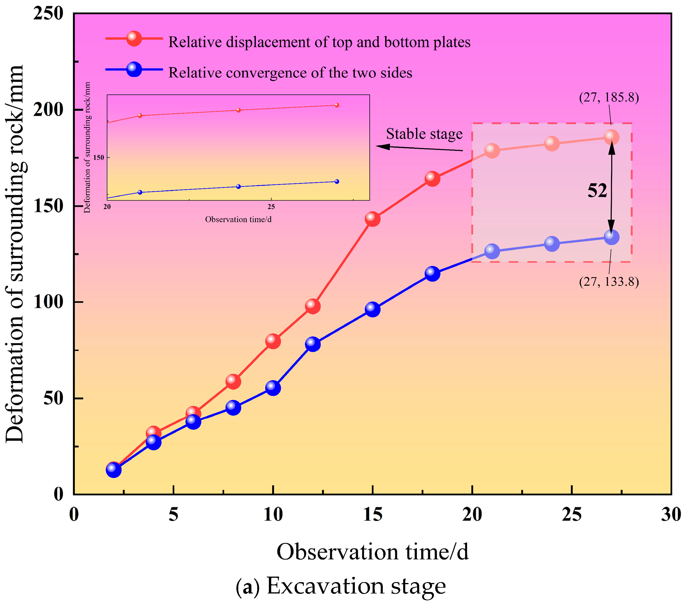
For analysis of the control effect of gob-side entry driving, the “crisscross measurement” is used to monitor the relative movement of the roof, floor, and ribs during roadway driving and mining [31,32,33,34,35]. The force situation of the anchor cable is intuitively calculated using the roadway anchor cable dynamometer. The results of the mining pressure observation is shown in Figure 10.


Figure 10.
Deformation curve of surrounding rock in gob-side entry driving.
As shown in Figure 10a, during the driving stage, 21110 working face’s track roadway experiences a rapid deformation of the surrounding rock, ranging from 2 to 20 days, in the roof and floor displacement more than in the ribs, with a maximum difference of 52 mm. The roadway roof and floor experience relative displacement of 185 mm, while the ribs have moved a distance of 133 mm in relation to each other. Ten days ago, the relative displacement of the roof, floor and ribs showed a linear trend; from 10 to 20 days, the roof and floor show a non-linear and rapid increase, while the changes in the ribs are relatively stable; after 20 days, although the deformation continues to increase, the growth is slow and has reached a stable stage.
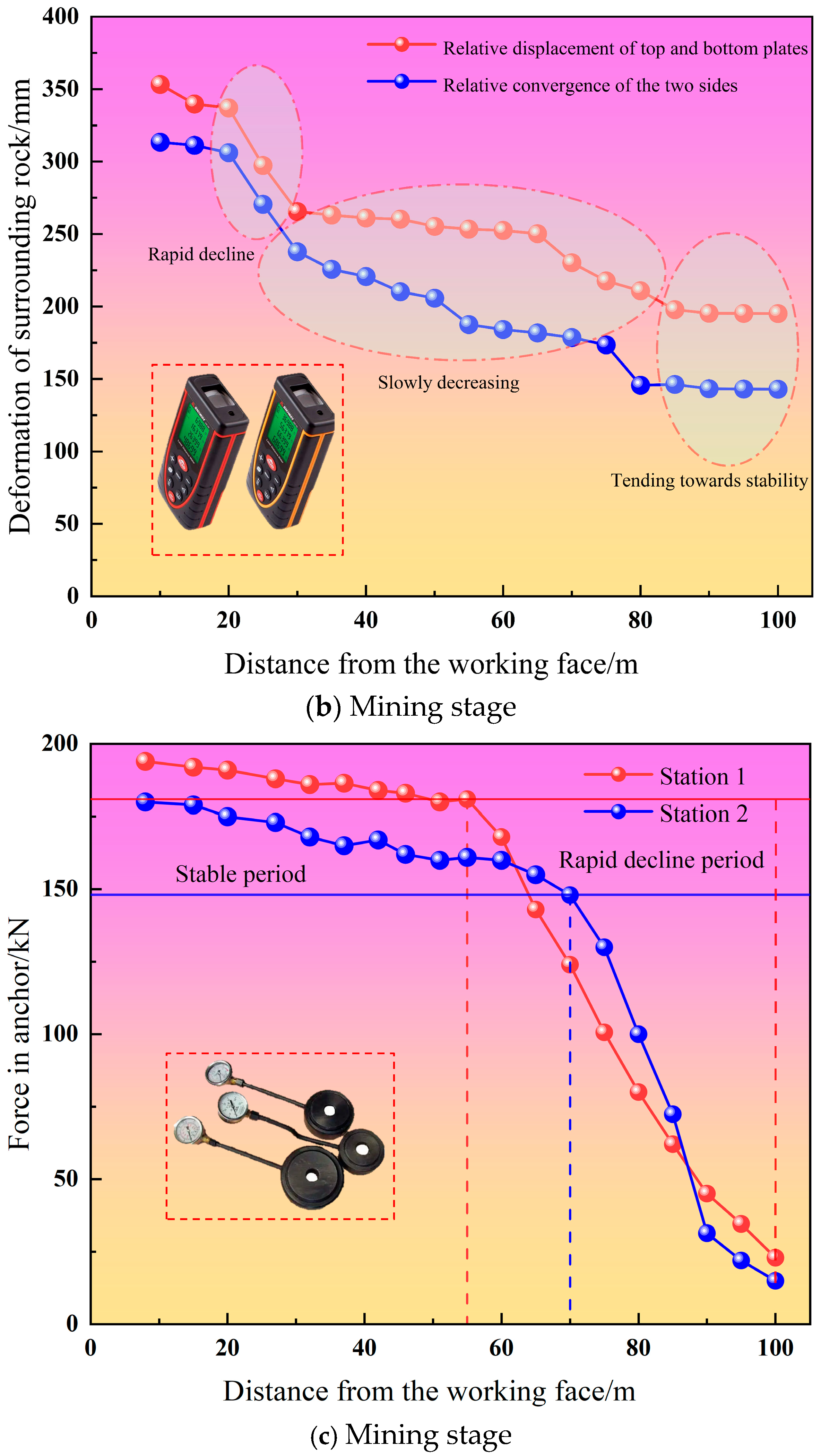
As shown in Figure 10b, roadway rangefinder data reveal a consistent pattern of deformation in the track roadway’s roof and floor, along with the adjacent rib rock, during mining. However, the deformation of the ribs’ surrounding rock exceeds that of the roof and floor. At approximately 25 m from the working surface, the adjacent rock undergoes swift alterations, exhibiting a 270 mm relative displacement between the roof and floor and a 297 mm relative displacement between the ribs; between 25 and 80 m from the mining zone, there is a noticeable reduction in the rate of deformation in the rock formations. The distance between the roof and floor experiences a relative displacement of 145 mm, and the ribs a relative displacement of 210 mm. However, after exceeding 80 m, the deformation of the surrounding rock remains basically unchanged.
As shown in Figure 10c, at the beginning phase, the anchor cables near the working face are affected by roadway deformation and mining disturbance. To keep the roadway stable, the anchor cables need to bear greater forces. At this time, the force on the anchor cables is relatively stable, and on those at stations 1 and 2 is less than 200 kN, both within the range of force for the roadway anchor cables; at a distance from the working face, the values of the roadway anchor cable strain gauge rapidly decreased. Those for station 1 decreased at a distance of 55 m from the working face, while those at station 2 began to decrease at a distance of 70 m from the working face. Their changes are 58 kN and 33 kN.
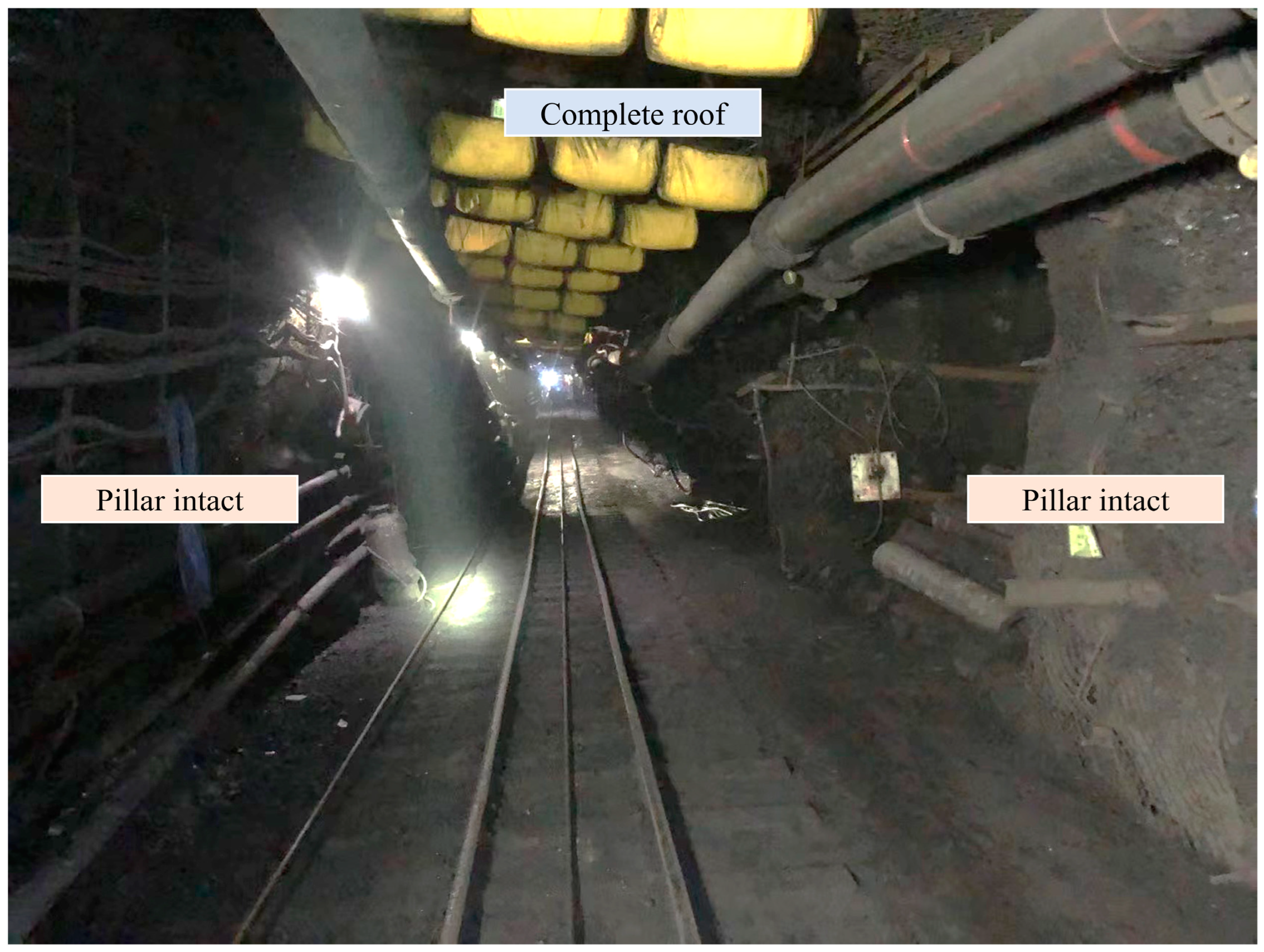
Therefore, the track roadway surrounding rock in the 21110 working face exhibits deformation that falls within an acceptable range, with the overall deformation being minimal and well-controlled. Moreover, roadway anchor cable force is stable, indicating that the design of the roadway support parameters and the rationality of the 8 m coal pillar width are successful. The control effect after the stabilization of the surrounding rock on site is shown in Figure 11.
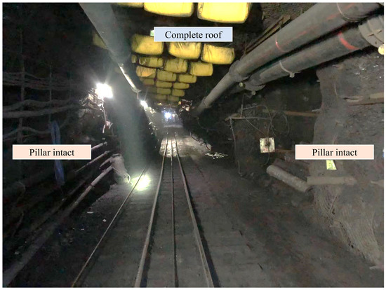
Figure 11.
On site surrounding rock control effectiveness.
7. Conclusions
- (1)
- According to the limit equilibrium theory, a reasonable value range for the coal pillar in gob-side entry driving is 7.9~9.8 m. The results of the numerical simulation demonstrate that, when the width of the coal pillar is 7.0 m, 8.0 m, 9.0 m, and 10.0 m, the stress and plastic zone of the roadway’s surrounding rock show significant differential distribution characteristics. Moreover, when the coal pillar width is 8.0 m, this is beneficial to the stability of the surrounding rock in gob-side entry driving. Therefore, a reasonable width for the coal pillar is 8.0 m.
- (2)
- The borehole observation results show that, within a sector area 2.1 m away from the mining coal pillar, 1.4 m from the left shoulder corner, 3.5 m from the roadway roof, 1.8 m from the right shoulder corner, and 1.7 m from the solid coal pillar, significant transverse and longitudinal fissures have developed inside the surrounding rock. The depth of the surrounding rock damage at the coal pillar side shoulder nest position is significant and exhibits asymmetric distortion characteristics. Therefore, it is proposed that the coal pillar side shoulder nest position be considered a key area for track roadway support, and the extent of the anchor cable on the left shoulder corner of the trackway roof and the roof should not be less than 4.5 m and 5.2 m, respectively.
- (3)
- Engineering practice has shown that the relative displacement of the roof and floor during the excavation of the roadway consistently exceeds that of the sides or ribs, with a maximum deformation of 185 mm for the roof and floor and 133 mm for the ribs, and with a maximum difference of 52 mm. The maximum deformation of the roof and floor during the mining period of the roadway is 353 mm, and the maximum deformation of the ribs is 313 mm. The mining pressure manifestation is normal. Through engineering practice, it is proven that setting up an 8.0 m coal pillar and adopting asymmetric coupling support technology effectively ensures the stability of the surrounding rock, achieving safe production of coal resources at the working face.
Author Contributions
Writing—original draft preparation, S.Y. and X.Z.; writing—review and editing, X.Z. and E.W.; supervision, S.Y., E.W. and Y.Y.; funding acquisition, S.Y. and E.W.; resources, visualization. X.Z. and K.H.; Software, J.M. and Y.W. All authors have read and agreed to the published version of the manuscript.
Funding
This research is supported by the National Natural Science Foundation of China (No. 52474097 and 52274081), the Natural Science Foundation of Hebei Province of China (No. E2021508011 and E2024508008), and the Science and Technology Project of Hebei Education Department (Grant no. QN2024235), the Langfang Science and Technology Research and Development Plan Self-Funded Project (No. 2024013030), the Fundamental Research Funds for the Central Universities (3142024013).
Data Availability Statement
The datasets generated or analyzed during the current study are available from the corresponding author on reasonable request.
Acknowledgments
The author team thanks the field technicians for providing the field test conditions and the ground pressure observation conditions.
Conflicts of Interest
The authors declare that the research is conducted in the absence of any commercial or financial relationships that could be construed as potential conflicts of interest.
References
- Kang, H.; Gao, F.; Xu, G.; Ren, H. Mechanical behaviors of coal measures and ground control technologies for China’s deep coal mines—A review. J. Rock Mech. Geotech. Eng. 2023, 15, 37–65. [Google Scholar] [CrossRef]
- Ranjith, P.; Zhao, J.; Ju, M.; De Silva, R.; Rathnaweera, T.; Bandara, A. Opportunities and Challenges in Deep Mining: A Brief Review. Engineering 2017, 3, 546–551. [Google Scholar] [CrossRef]
- Tao, M.; Cheng, W.; Nie, K.; Zhang, X.; Cao, W. Life cycle assessment of underground coal mining in China. Sci. Total Environ. 2022, 805, 150231. [Google Scholar] [CrossRef]
- Liu, X.; Li, L.; Yang, Y. Development status of coal mining in China. J. S. Afr. Inst. Min. Metall. 2023, 123, 19–27. [Google Scholar] [CrossRef]
- Ren, S.; Zheng, D.; Qu, Y.; Qin, R.; Jiao, X.; Bai, J. Development Assessment of the Coal Industry of China Based on the Minimum Deviation Comprehensive Weight Evaluation Model. Adv. Civ. Eng. 2021, 2021, 5248324. [Google Scholar] [CrossRef]
- Huang, P.; Zhang, Q.; Xie, J.; Li, J.; Zhang, Q.; Li, M.; Simao, F. Multiscale study on coal pillar strength and rational size under variable width working face. Front. Environ. Sci. 2024, 12, 1338642. [Google Scholar] [CrossRef]
- Du, B.; Liu, C.; Yang, J.; Wu, F. Abutment pressure distribution pattern and size optimization of coal pillar under repeated mining: A case study. Arab. J. Geosci. 2020, 13, 1261. [Google Scholar] [CrossRef]
- Chen, A. Width Design of Small Coal Pillar of Gob-Side Entry Driving in Soft Rock Working Face and Its Application of Zaoquan Coal Mine. Adv. Civ. Eng. 2021, 2021, 9999957. [Google Scholar] [CrossRef]
- Jiang, L.; Yang, Z.; Li, G. Research on the Reasonable Coal Pillar Width and Surrounding Rock Supporting Optimization of Gob-Side Entry under Inclined Seam Condition. Adv. Civ. Eng. 2021, 2021, 7145821. [Google Scholar] [CrossRef]
- Xu, Q.; Bai, J.; Yan, S.; Wang, R.; Wu, S.; Chu, T. Numerical Study on Soft Coal Pillar Stability in an Island Longwall Panel. Adv. Civ. Eng. 2021, 2021, 8831778. [Google Scholar] [CrossRef]
- Kang, H.; Yang, J.; Jiang, P.; Gao, F.; Li, W.; Li, J.; Chen, H. Theory, technology and application of grouted bolting in soft rock roadways of deep coal mines. Int. J. Miner. Metall. Mater. 2024, 31, 1463–1479. [Google Scholar] [CrossRef]
- Jiang, Z.; Guo, W.; Xie, S. Coal Pillar Size Determination and Surrounding Rock Control for Gob-Side Entry Driving in Deep Soft Coal Seams. Processes 2023, 11, 2331. [Google Scholar] [CrossRef]
- Wang, E.; Xie, S. Determination of coal pillar width for gob-side entry driving in isolated coal face and its control in deep soft-broken coal seam: A case study. Energy Sci. Eng. 2022, 10, 2305–2316. [Google Scholar] [CrossRef]
- Wang, D.; He, F.; Wu, Y.; Xu, X.; Zhang, J.; Lv, K.; Li, L.; Zhai, W.; Song, J. Study on surrounding rock failure mechanism and rational coal pillar width of the gob-side coal roadway under influence of intense dynamic pressure. Energy Sci. Eng. 2023, 11, 1716–1733. [Google Scholar] [CrossRef]
- Wang, M.; Li, X.; Su, J.; Liu, W.; Fang, Z.; Wang, S.; Kang, J.; Yu, W. A study on the reasonable width of narrow coal pillars in the section of hard primary roof hewing along the air excavation roadway. Energy Sci. Eng. 2024, 12, 2746–2765. [Google Scholar] [CrossRef]
- Chen, Y.; Sun, J.; Pang, D.; Zhang, R. Deformation and Failure Law of Roadway along Goaf and Reserve Width of Section Coal Pillar. Geofluids 2022, 2022, 9947113. [Google Scholar] [CrossRef]
- Huang, W.; Liu, S.; Gao, M.; Hou, T.; Wang, X.; Zhao, T.; Sui, L.; Xie, Z. Improvement of Reinforcement Performance and Engineering Application of Small Coal Pillars Arranged in Double Roadways. Sustainability 2023, 15, 292. [Google Scholar] [CrossRef]
- Zhang, S.; Wang, X.; Fan, G.; Zhang, D.; Cui, J. Pillar size optimization design of isolated island panel gob-side entry driving in deep inclined coal seam-case study of Pingmei No. 6 coal seam. J. Geophys. Eng. 2018, 15, 816–828. [Google Scholar] [CrossRef]
- Zhu, L.; Liu, C.; Gu, W.; Yuan, C.; Wu, Y.; Liu, Z.; Song, T.; Sheng, F. Research on Floor Heave Mechanisms and Control Technology for Deep Dynamic Pressure Roadways. Processes 2023, 11, 467. [Google Scholar] [CrossRef]
- Liu, H.; Zhang, B.; Li, X.; Liu, C.; Wang, C.; Wang, F.; Chen, D. Research on roof damage mechanism and control technology of gob-side entry retaining under close distance gob. Eng. Fail. Anal. 2022, 138, 106331. [Google Scholar] [CrossRef]
- He, M.; Wang, Q. Rock dynamics in deep mining. Int. J. Min. Sci. Technol. 2023, 33, 1065–1082. [Google Scholar] [CrossRef]
- Ma, Q.; Zhang, Y.; Gao, L.; Li, Z.; Song, G.; Zheng, Y. The Optimization of Coal Pillars on Return Air Sides and the Reasonable Horizon Layout of Roadway Groups in Highly Gassy Mines. Sustainability 2022, 14, 9417. [Google Scholar] [CrossRef]
- Jawed, M.; Sinha, R. Design of rhombus coal pillars and support for Roadway Stability and mechanizing loading of face coal using SDLs in a steeply inclined thin coal seam-a technical feasibility study. Arab. J. Geosci. 2018, 11, 415. [Google Scholar] [CrossRef]
- Chang, Q.; Ge, S.; Shi, X.; Sun, Y.; Wang, H.; Li, M.; Wang, Y.; Wu, F. Determination of Narrow Coal Pillar Width and Roadway Surrounding Rock Support Technology in Gob Driving Roadway. Sustainability 2022, 14, 4848. [Google Scholar] [CrossRef]
- Xu, Y.; Pan, K.; Zhang, H. Investigation of key techniques on floor roadway support under the impacts of superimposed mining: Theoretical analysis and field study. Environ. Earth Sci. 2019, 78, 436. [Google Scholar] [CrossRef]
- Wang, B.; Dang, F.; Gu, S.; Huang, R.; Miao, Y.; Chao, W. Method for determining the width of protective coal pillar in the pre-driven longwall recovery room considering main roof failure form. Int. J. Rock Mech. Min. Sci. 2020, 130, 104340. [Google Scholar] [CrossRef]
- Ghasemi, E.; Shahriar, K. A new coal pillars design method in order to enhance safety of the retreat mining in room and pillar mines. Saf. Sci. 2012, 50, 579–585. [Google Scholar] [CrossRef]
- Wei, G. Study on the width of the non-elastic zone in inclined coal pillar for strip mining. Int. J. Rock Mech. Min. Sci. 2014, 72, 304–310. [Google Scholar] [CrossRef]
- Yin, S.; Zheng, X.; Wang, E.; Kang, Q.; Zhang, X. Non-uniform failure and differential pressure relief technology of roadway under irregular goafs in deep close-distance coal seams. Sci. Rep. 2023, 13, 18527. [Google Scholar] [CrossRef]
- Yin, S.; Zuo, A.; Ma, L.; Ren, Y.; Shi, S. Study on surrounding rock stability of gob-side entry driving with narrow coal pillar in medium thick coal seam. Coal Eng. 2022, 54, 90–96. [Google Scholar]
- Wang, E.; Yin, S.; Zhao, Q.; Kang, Q.; Zheng, X. Control Effect Analysis and Engineering Application of Anchor Cable Beam-Truss Structure on Large-Deformation Roadway in Deep Coal Mine. Shock Vib. 2024, 2024, 2987574. [Google Scholar] [CrossRef]
- Zhao, W.; Long, G.; Li, J. Analysis of stress distribution law of surrounding rock of rectangular roadway with different specifications based on complex variable function. Conserv. Util. Miner. Resour. 2024, 44, 111–123. [Google Scholar] [CrossRef]
- Wang, E.; Yin, S.; Kang, Q.; Zhao, X.; Lan, Q.; Sheng, H.; Liang, H. Coupling control technology of anchoring and unloading in deep intense-mining and large-deformation roadway: A case study. Sci. Rep. 2024, 14, 12075. [Google Scholar] [CrossRef]
- Sha, X.; Chen, C.; Li, J. Numerical simulation of the impact of geostress on the stability and rockburst susceptibility of large cross–section roadways at julong copper mine. Conserv. Util. Miner. Resour. 2024, 44, 52–57. [Google Scholar] [CrossRef]
- Li, P.; Jiang, G.; Li, H. Study on failure characteristics and control technology of surrounding rock in deep soft rock roadway of a coal mine. Conserv. Util. Miner. Resour. 2024, 44, 58–64. [Google Scholar] [CrossRef]


Disclaimer/Publisher’s Note: The statements, opinions and data contained in all publications are solely those of the individual author(s) and contributor(s) and not of MDPI and/or the editor(s). MDPI and/or the editor(s) disclaim responsibility for any injury to people or property resulting from any ideas, methods, instructions or products referred to in the content. |
© 2025 by the authors. Licensee MDPI, Basel, Switzerland. This article is an open access article distributed under the terms and conditions of the Creative Commons Attribution (CC BY) license (https://creativecommons.org/licenses/by/4.0/).