


An Experimental Study on the Flash Boiling Characteristics of Liquid Ammonia Spray in a Constant Volume Chamber under High Injection Pressure

 ,
, 
Abstract
1. Introduction
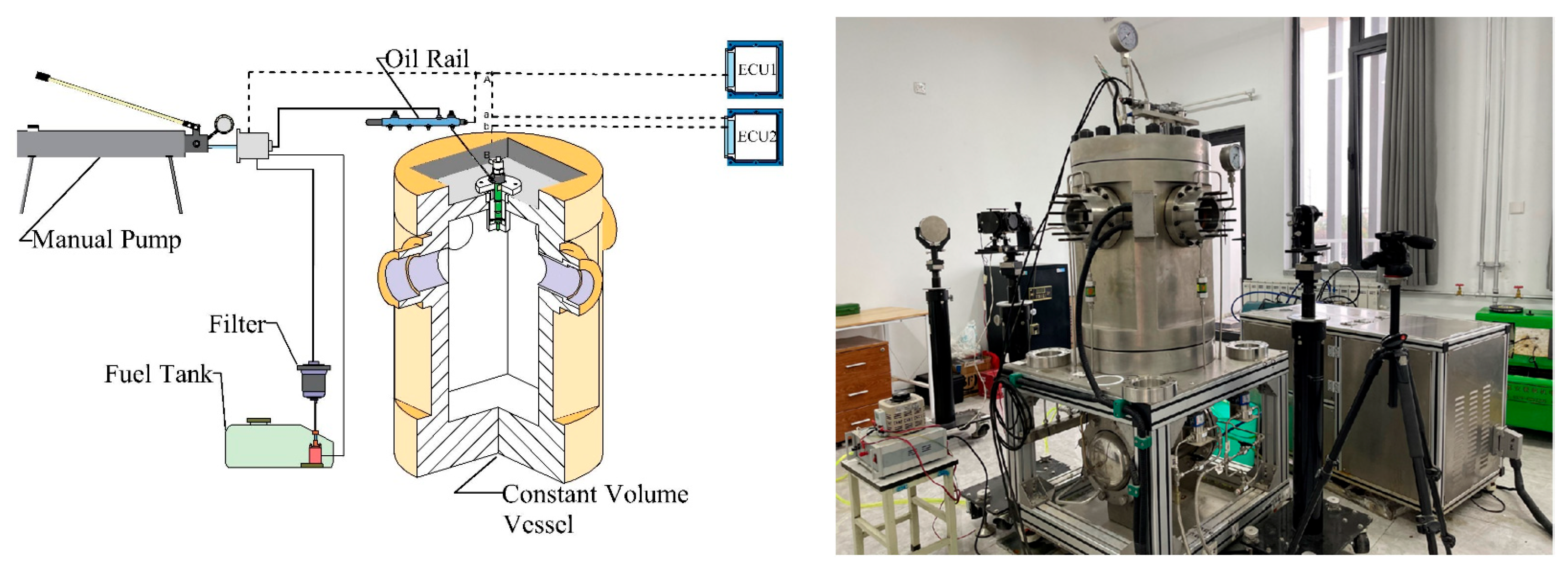
2. Experimental Setup and Procedure
2.1. Experimental Setup
2.2. Test Conditions and Procedure
3. Results and Discussion
3.1. Effect of Injection Pressure of Ammonia on Spray
3.1.1. Non-Flash Boiling Spray
3.1.2. Transition Flash Boiling Spray
3.1.3. Flash Boiling Spray
3.2. Influence of Ambient Pressure on Liquid Ammonia Spray and the Appearance of Spray Resistance Phenomenon
3.2.1. Influence of Ambient Pressure on Three Kinds of Spray under 70 MPa Injection Pressure
3.2.2. Effect of Ambient Pressure on Spray under 80 MPa Injection Pressure
4. Conclusions
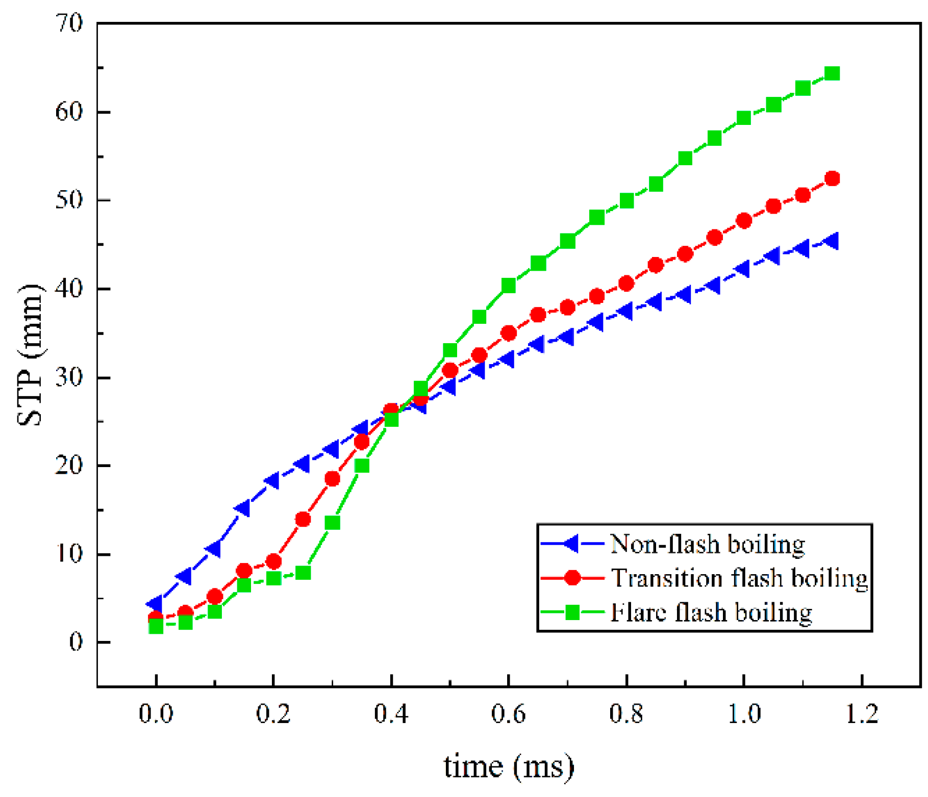
- The gas–liquid STP of cold spray was not significantly changed by the injection pressure, although the STP was increased to some extent. For flash boiling spray, including transition and flare flash boiling sprays, the STP of the gas and liquid increased more than that of cold spray, and the fluctuation of the late spray was relatively large. Therefore, the injection pressure has a greater effect on the penetration distance of flash boiling spray.
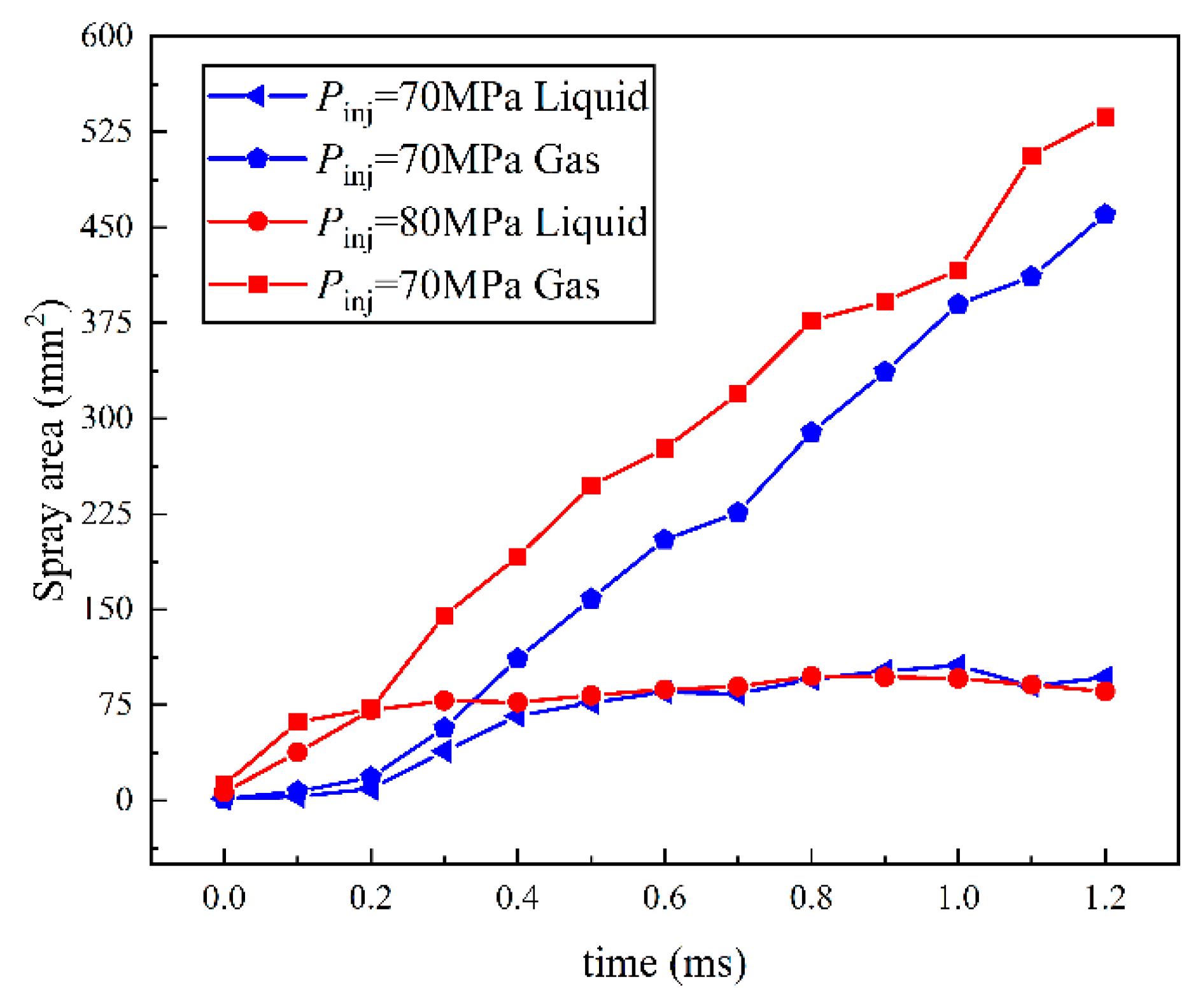
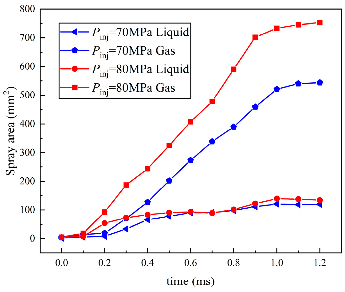
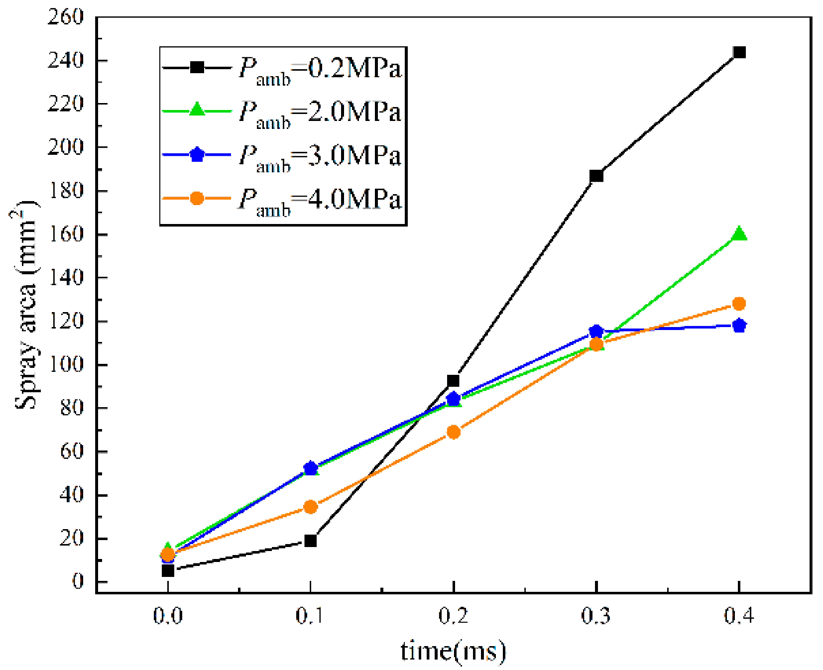
- The variation trend of spray area was consistent with the STP, confirming the accuracy of the experiment. Under the influence of injection pressure, the separation time of the spray area is earlier than that of gas–liquid STP. The liquid spray area of the three kinds of spray is not affected by the injection pressure, and the final area of the liquid phase region is similar to that of the development of spray. The growth of the gas area is greatly affected by the injection pressure. Meanwhile, the gas area of flare and transition flash boiling spray is much larger than that of cold spray, and the growth degree of flash boiling spray is greater than that of cold spray.
- The spray resistance phenomenon was confirmed by comparing the STP of spray under three states with that under different ambient pressures. Under the spray pressure of 70 MPa, the spray appears at the inter section point of approximately 0.4 ms, and the spray resistance phenomenon appears before 0.4 ms. The ambient pressure of flash boiling spray is much smaller than that of cold spray. At a low environmental density, the STP of spray is abnormally shortened. Spray resistance increased to approximately 0.15 ms as the injection pressure increased. Since the ambient pressure of flash boiling spray was only 0.2 MPa, which was much lower than that under the other three kinds of cold spray, the spray resistance also occurred.
Author Contributions
Funding
Data Availability Statement
Acknowledgments
Conflicts of Interest
References
- Pham, Q.; Park, S.; Agarwal, A.K.; Park, S. Review of dual-fuel combustion in the compression-ignition engine: Spray, combustion, and emission. Energy 2022, 250, 123778. [Google Scholar] [CrossRef]
- Yang, W.; Ranga Dinesh, K.K.J.; Luo, K.H.; Thevenin, D. Direct numerical simulation of turbulent premixed ammonia and ammonia-hydrogen combustion under engine-relevant conditions. Int. J. Hydrogen Energy 2022, 47, 11083–11100. [Google Scholar] [CrossRef]
- Liu, Z.; Zhou, L.; Zhong, L.; Wei, H. Enhanced combustion of ammonia engine based on novel air-assisted pre-chamber turbulent jet ignition. Energy Convers. Manag. 2023, 276, 116526. [Google Scholar] [CrossRef]
- Scharl, V.; Lackovic, T.; Sattelmayer, T. Characterization of ammonia spray combustion and mixture formation under high-pressure, direct injection conditions. Fuel 2023, 333, 126454. [Google Scholar] [CrossRef]
- Li, S.; Li, T.; Wang, N.; Zhou, X.; Chen, R.; Yi, P. An investigation on near-field and far-field characteristics of superheated ammonia spray. Fuel 2022, 324, 124683. [Google Scholar] [CrossRef]
- Wang, N.; Huang, S.; Zhang, Z.; Li, T.; Yi, P.; Wu, D.; Chen, G. Laminar burning characteristics of ammonia/hydrogen/air mixtures with laser ignition. Int. J. Hydrogen Energy 2021, 46, 31879–31893. [Google Scholar] [CrossRef]
- Dimitriou, P.; Javaid, R. A review of ammonia as a compression ignition engine fuel. Int. J. Hydrogen Energy 2020, 45, 7098–7118. [Google Scholar] [CrossRef]
- Liu, X.; Tang, Q.; Im, H.G. Enhancing ammonia engine efficiency through pre-chamber combustion and dual-fuel compression ignition techniques. J. Clean. Prod. 2024, 436, 140622. [Google Scholar] [CrossRef]
- Zhang, Z.; Long, W.; Dong, P.; Tian, H.; Tian, J.; Li, B.; Wang, Y. Performance characteristics of a two-stroke low speed engine applying ammonia/diesel dual direct injection strategy. Fuel 2023, 332, 126086. [Google Scholar] [CrossRef]
- Pelé, R.; Mounaïm-Rousselle, C.; Bréquigny, P.; Hespel, C.; Bellettre, J. First Study on Ammonia Spray Characteristics with a Current GDI Engine Injector. Fuels 2021, 3, 253–271. [Google Scholar] [CrossRef]
- Liu, X.; Yao, X.; Wang, Z.; Tang, C. Single hole ammonia spray macroscopic and microscopic characteristics at flare and transition flash boiling regions. Appl. Therm. Eng. 2023, 235, 121443. [Google Scholar] [CrossRef]
- Settles, G.S. Schlieren and Shadowgraph Techniques: Visualizing Phenomena in Transport Media. Appl. Mech. Rev. 2002, 55, B76. [Google Scholar] [CrossRef]
- Gladstone, J.H.; Dale, T.P. Researches on the Refraction, Dispersion, and Sensitiveness of Liquids. Philos. Trans. R. Soc. Lond. 1863, 153, 317–343. [Google Scholar]
- Lewandowski, M.T.; Pasternak, M.; Haugsvær, M.; Løvås, T. Simulations of ammonia spray evaporation, cooling, mixture formation and combustion in a direct injection compression ignition engine. Int. J. Hydrogen Energy 2023, 52, 916–935. [Google Scholar] [CrossRef]
- Huang, Z.; Wang, H.; Luo, K.; Fan, J. Large eddy simulation investigation of ammonia spray characteristics under flash and non-flash boiling conditions. Appl. Energy Combust. Sci. 2023, 16, 100220. [Google Scholar] [CrossRef]
- An, Z.; Xing, J.; Kurose, R. Numerical study on the phase change and spray characteristics of liquid ammonia flash spray. Fuel 2023, 345, 128229. [Google Scholar] [CrossRef]
- Xu, M.; Zhang, Y.; Zeng, W.; Zhang, G.; Zhang, M. Flash Boiling: Easy and Better Way to Generate Ideal Sprays than the High Injection Pressure. SAE Int. J. Fuels Lubr. 2013, 6, 137–148. [Google Scholar] [CrossRef]
- Zhang, Z.; Li, T.; Chen, R.; Wang, N.; Wei, Y.; Wu, D. Injection characteristics and fuel-air mixing process of ammonia jets in a constant volume vessel. Fuel 2021, 304, 121408. [Google Scholar] [CrossRef]
- Zhang, Y.; Xu, L.; Zhu, Y.; Xu, S.; Bai, X.-S. Numerical study on liquid ammonia direct injection spray characteristics under engine-relevant conditions. Appl. Energy 2023, 334, 120680. [Google Scholar] [CrossRef]
- Gao, S.; Yan, J.; Lee, T.H.; Lee, C.-F. Model development for flash boiling spray and validations with isooctane, hexane, ethanol and their binary mixtures. Fuel 2022, 321, 123917. [Google Scholar] [CrossRef]
- Fang, Y.; Ma, X.; Zhang, Y.; Li, Y.; Zhang, K.; Jiang, C.; Wang, Z.; Shuai, S. Experimental Investigation of High-Pressure Liquid Ammonia Injection under Non-Flash Boiling and Flash Boiling Conditions. Energies 2023, 16, 2843. [Google Scholar] [CrossRef]
- Liu, X.; Zaihi, A.; Al-lehaibi, M.; Mohan, B.; AlRamadan, A.; Cenker, E.; Im, H.G. Investigation of the Cryogenic Nitrogen and Non-Cryogenic N-Dodecane and Ammonia Injections using a Real-Fluid Modelling Approach. SAE Int. J. Adv. Curr. Pract. Mobil. 2022, 5, 1129–1141. [Google Scholar] [CrossRef]
- Liu, X.; Guo, J.; Im, H.G. Development of correlation model for cavitating spray using Eulerian simulations. Int. J. Engine Res. 2023, 25, 613–630. [Google Scholar] [CrossRef]
- Ainsalo, A.; Sallinen, R.; Kaario, O.; Larmi, M. Optical investigation of spray characteristics for light fuel oil, kerosene, hexane, methanol, and propane. At. Sprays 2019, 29, 521–544. [Google Scholar] [CrossRef]


| Items | Parameters |
|---|---|
| Ambient temperature (Tamb, K) | 500 |
| Ambient pressure (Pamb, MPa) | 0.2, 0.6, 2, 3, 4 |
| Injection pressure (Pinj, MPa) | 70, 80 |
| Fuel | Liquid ammonia |
| Fuel temperature (Tf, K) | 320 |
| Spray hole diameter (mm) | 0.14 |
| Fuel saturated vapor pressure (MPa) | 1.87 |
| Injection duration (ms) | 1.0 |
| Cases | Pamb (MPa) | Pamb (MPa) | Ambient Gas | Spray State | Rp |
|---|---|---|---|---|---|
| 1 | 0.2 | 70 | N2 | Flare flash boiling | 0.11 |
| 2 | 80 | ||||
| 3 | 0.6 | 70 | N2 | Transition flash boiling | 0.32 |
| 4 | 80 | ||||
| 5 | 2 | 70 | N2 | Non-flash boiling | 1.07 |
| 6 | 80 | ||||
| 7 | 3 | 70 | N2 | Non-flash boiling | 1.60 |
| 8 | 80 | ||||
| 9 | 4 | 70 | N2 | Non-flash boiling | 2.14 |
| 10 | 80 |
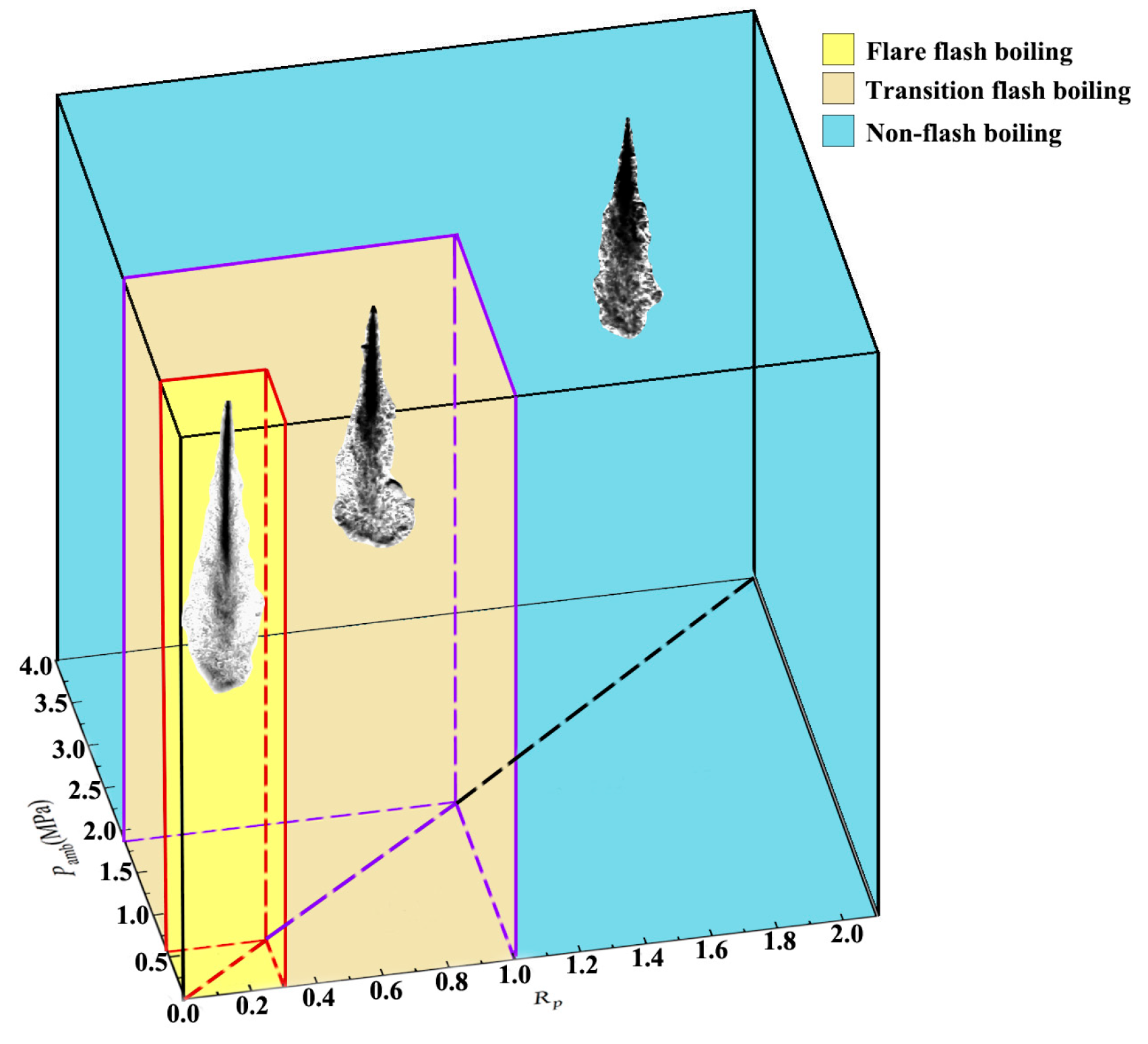
| Superheat Range | Spray Type |
|---|---|
| Rp < 0.3 | Flare flash boiling |
| 0.3 < Rp < 1.0 | Transition flash boiling |
| 1.0 < Rp | Non-flash boiling spray |
| Fuel | 0.0 ms | 0.1 ms | 0.2 ms | 0.3 ms | 0.4 ms | 0.5 ms | 0.6 ms |
|---|---|---|---|---|---|---|---|
| Ammonia (70 MPa) |  | ||||||
| Ammonia (80 MPa) |  | ||||||
| Fuel | 0.0 ms | 0.1 ms | 0.2 ms | 0.3 ms | 0.4 ms | 0.5 ms | 0.6 ms |
|---|---|---|---|---|---|---|---|
| Ammonia (70 MPa) | 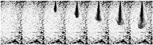 | ||||||
| Ammonia (80 MPa) | 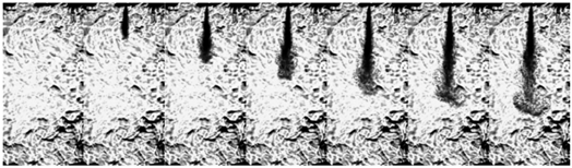 | ||||||
| Fuel | 0.0 mms | 0.1 ms | 0.2 ms | 0.3 ms | 0.4 ms | 0.5 ms | 0.6 ms |
|---|---|---|---|---|---|---|---|
| Ammonia (70 MPa) | 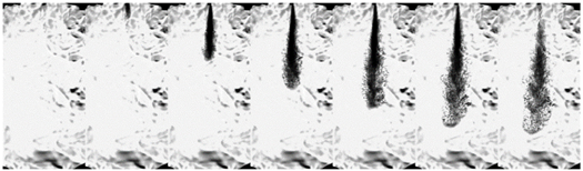 | ||||||
| Ammonia (80 MPa) | 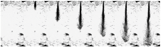 | ||||||
| Fuel | 0.0 ms | 0.1 ms | 0.2 ms | 0.3 ms | 0.4 ms |
|---|---|---|---|---|---|
| Pamb = 0.2 MPa |  | ||||
| Pamb = 2.0 MPa | 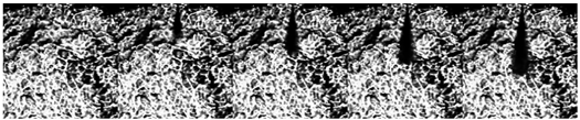 | ||||
| Pamb = 3.0 MPa | 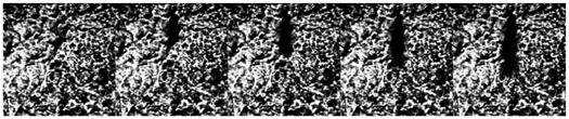 | ||||
| Pamb = 4.0 MPa | 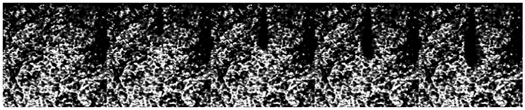 | ||||
Disclaimer/Publisher’s Note: The statements, opinions and data contained in all publications are solely those of the individual author(s) and contributor(s) and not of MDPI and/or the editor(s). MDPI and/or the editor(s) disclaim responsibility for any injury to people or property resulting from any ideas, methods, instructions or products referred to in the content. |
© 2024 by the authors. Licensee MDPI, Basel, Switzerland. This article is an open access article distributed under the terms and conditions of the Creative Commons Attribution (CC BY) license (https://creativecommons.org/licenses/by/4.0/).
Share and Cite
He, H.; Wu, J.; Wang, L.; Lou, H.; Li, S.; Huang, L.; Chen, Z. An Experimental Study on the Flash Boiling Characteristics of Liquid Ammonia Spray in a Constant Volume Chamber under High Injection Pressure. Processes 2024, 12, 1076. https://doi.org/10.3390/pr12061076
He H, Wu J, Wang L, Lou H, Li S, Huang L, Chen Z. An Experimental Study on the Flash Boiling Characteristics of Liquid Ammonia Spray in a Constant Volume Chamber under High Injection Pressure. Processes. 2024; 12(6):1076. https://doi.org/10.3390/pr12061076
Chicago/Turabian StyleHe, Haibin, Jie Wu, Lei Wang, Hua Lou, Songfeng Li, Lvmeng Huang, and Zhanming Chen. 2024. "An Experimental Study on the Flash Boiling Characteristics of Liquid Ammonia Spray in a Constant Volume Chamber under High Injection Pressure" Processes 12, no. 6: 1076. https://doi.org/10.3390/pr12061076
APA StyleHe, H., Wu, J., Wang, L., Lou, H., Li, S., Huang, L., & Chen, Z. (2024). An Experimental Study on the Flash Boiling Characteristics of Liquid Ammonia Spray in a Constant Volume Chamber under High Injection Pressure. Processes, 12(6), 1076. https://doi.org/10.3390/pr12061076