
Dynamic Reserve Calculation Method of Fractured-Vuggy Reservoir Based on Modified Comprehensive Compression Coefficient


Abstract
1. Introduction
2. Modification of Comprehensive Compression Coefficient
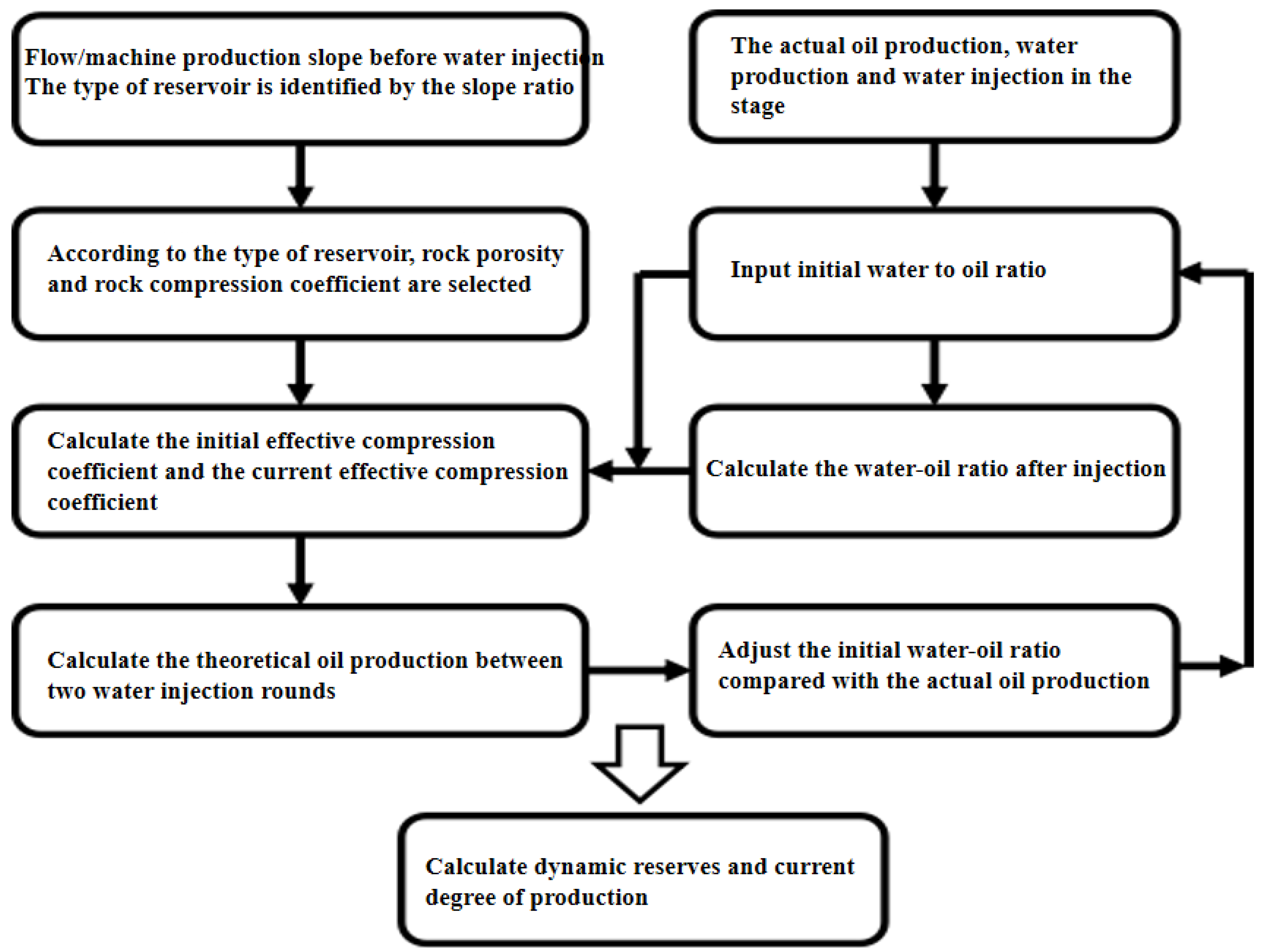
2.1. Main Research Methods
- (1)
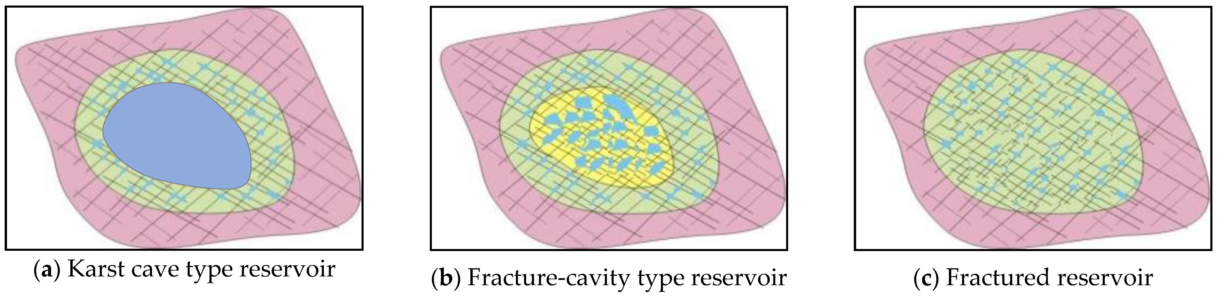
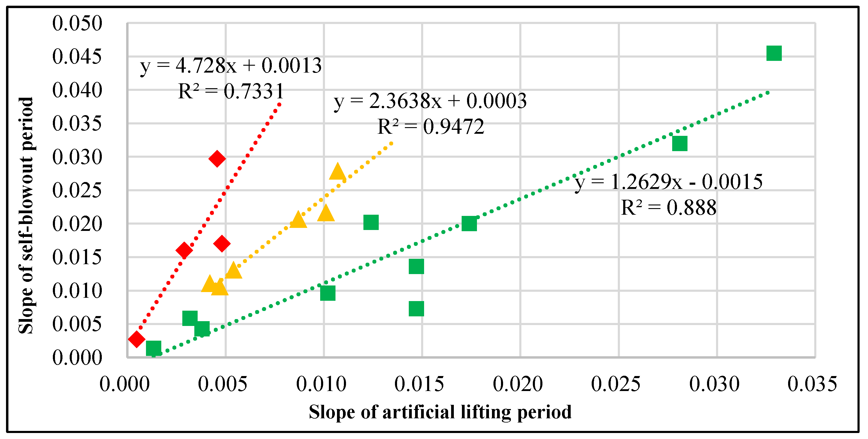
- Utilizing production indicator and water injection curves, the reservoir group type is determined as follows: karst cave type exhibits minimal changes in slope across multiple water injection cycles and a stable supply radius; fracture-vuggy type shows significant slope variation and an increased supply radius with each cycle; and fractured type experiences substantial reserve loss with each additional water injection cycle, attributed to fracture closure.
- (2)
- The reservoir’s comprehensive compression coefficient (Ct) is meticulously determined by correlating rock porosity with the dynamic water–oil ratio, which is derived from the initial water–oil ratio data and adjusted in response to variations in oil and water production rates.
- (3)
- By constraining the water–oil ratio with stage oil production data and calculating the relative error rate and dynamic reserves, the current degree of extraction is analyzed, involving the input of stage oil production data, fitting theoretical stage oil production volumes for various initial water–oil ratios, and refining the initial water–oil ratio based on the relative error rate of stage oil production, followed by computing dynamic reserves under low error rate conditions.
2.2. Classification of Reservoir Types
2.3. Compression Coefficient Correction
2.4. Calculation of Dynamic Reserves
3. Application for Calculating Dynamic Reserves of Fracture-Vuggy Reservoir
3.1. Well Introduction
3.2. Karst Cave Reservoir
3.3. Fracture-Cave Reservoir
3.4. Fractured Type Reservoir
3.5. Error Analysis
4. Conclusions
- (1)
- This study introduces a novel method for calculating dynamic reserves in fracture-cave reservoirs, predicated on an amended comprehensive compressibility coefficient. The approach commences with the identification of reservoir types through the analysis of production data, followed by the precise calibration of rock compressibility coefficients tailored to each type. Subsequently, the method employs the relative error rate of cumulative oil production to constrain the water–oil ratio of the reservoir, which in turn refines the comprehensive compressibility coefficient for dynamic reserve computation. This methodology enhances both the accuracy and reliability of reserve estimations.
- (2)
- The application of this refined methodology to the dynamic reserve calculations of 23 wells in the Tahe Oilfield has yielded a notably reduced error rate compared to existing methods, thereby enhancing the accuracy of these calculations. Specifically, for karst cave and fracture-vuggy reservoirs, the error rate for dynamic reserve estimation is below 10%, surpassing the conventional method’s error rate by over fivefold. In fractured reservoirs, while the error rate experiences minor fluctuations due to stress sensitivity, diversion capacity, and channel variation, it remains significantly lower than that of traditional methods.
Author Contributions
Funding
Data Availability Statement
Conflicts of Interest
References
- Yan, X.; Huang, Z.; Yao, J.; Zhang, Z.; Liu, P.; Li, Y.; Fan, D. Numerical simulation of hydro-mechanical coupling in fractured vuggy porous media using the equivalent continuum model and embedded discrete fracture model. Adv. Water Resour. 2019, 126, 137–154. [Google Scholar] [CrossRef]
- Wang, L.; Golfier, F.; Tinet, A.; Chen, W.; Vuik, C. An efficient adaptive implicit scheme with equivalent continuum approach for two-phase flow in fractured vuggy porous media. Adv. Water Resour. 2022, 163, 104186. [Google Scholar] [CrossRef]
- Liu, X.; Jiao, Z.; Qu, X. Calculation method of Ordovician seam reservoir in Tahe Oilfield. Spec. Oil Gas Reserv. 2005, 12, 22–24. [Google Scholar]
- Cheng, H. The Enhanced Oil Recovery Effect of Nitrogen-Assisted Gravity Drainage in Karst Reservoirs with Different Genesis: A Case Study of the Tahe Oilfield. Processes 2023, 11, 2316. [Google Scholar] [CrossRef]
- Zhou, X.; Li, X.; Shen, D.; Shi, L.; Zhang, Z.; Sun, X.; Jiang, Q. CO2 huff-n-puff process to enhance heavy oil recovery and CO2 storage: An integration study. Energy 2022, 239, 122003. [Google Scholar] [CrossRef]
- Aguilera, R. Effect of Fracture Compressibility on Oil Recovery From Stress-Sensitive Naturally Fractured Reservoirs. J. Can. Pet. Technol. 2006, 45, 2. [Google Scholar] [CrossRef]
- Liu, P.; Lin, J.; Tang, B.; Ren, K.; Huang, M.; Geng, C. Residual Oil Distribution Pattern in a Fault-Solution Carbonate Reservoir and Countermeasures to Improve Oil Development Effectiveness. Geofluids 2022, 2022, 2147200. [Google Scholar] [CrossRef]
- Zhou, X.; Yuan, Q.; Rui, Z.; Wang, H.; Feng, J.; Zeng, F.; Zhang, L. Feasibility study of CO2 huff-n-puff process to enhance heavy oil recovery via long core experiments. Appl. Energy 2019, 236, 526–539. [Google Scholar] [CrossRef]
- Liu, Y.; Liu, Y.; Zhang, Q.; Zheng, W.; Jian, C.; Li, G.; Xue, Y. Large-scale physical simulation experimental study on thick carbonate reservoirs. Pet. Geol. Recovery Effic. 2020, 27, 117–125. [Google Scholar]
- Li, K.; Li, Y.; Liu, M. Study on calculation method of seam type carbonate reservoir. Oil Drill. Process. 2007, 29, 103–104. [Google Scholar]
- Liu, Y.; Zhen, H. A Storage-Driven CO2 EOR for Net-zero Emission Target. Engineering 2022, 18, 79–87. [Google Scholar] [CrossRef]
- Liu, B.; Qi, L.; Li, Z.; Liu, J.; Huang, C.; Yang, L.; Ma, L.; Gong, W. Spatial characterization and quantitative description technology for ultra-deep fault-karst reservoirs in the Shunbei area. Acta Pet. Sin. 2020, 41, 412–420. [Google Scholar]
- Li, J.; Zhang, H. Application of material balance method in energy evaluation of seam carbonate reservoir. Pet. Nat. Gas Geol. 2009, 30, 773–778+785. [Google Scholar]
- Liu, Y.; Zhen, H.; Birol Dindoruk; Yang, T. Using Propanol as an Additive to CO2 for Improving CO2 Utilization and Storage in Oil Reservoirs. Appl. Energy 2022, 311, 118640. [Google Scholar] [CrossRef]
- Jing, W.; Wei, Z.; Huiqing, L.; Fangna, L.; Tuozheng, Z.; Liangbin, D.; Xinling, Y.; Bo, L. Inter-well interferences and their influencing factors during water flooding in fractured-vuggy carbonate reservoirs. Pet. Explor. Dev. 2020, 47, 1062–1073. [Google Scholar]
- Gu, H.; Wang, G.; Yang, M.; Cao, F.; Zheng, S.; Shang, G.; Zhu, L.; Han, D.; Kang, Z.; Zhao, Y.; et al. A method for estimating the drainage depth of oil well in ultra-deep fault-karst reservoirs and its guiding significance to oilfield development. Acta Pet. Sin. 2021, 42, 1202–1211. [Google Scholar]
- Xiong, Y.; Mei, S.; Jia, J. Application of water injection indicator curve in carbonate reservoir in oilfield development. Cont. Bridge Vis. 2012, 24, 128–130. [Google Scholar]
- Tang, B.; Ren, K.; Lu, H.; Li, C.; Geng, C.; Wei, L.; Chai, Z.; Wu, S. Study on Residual Oil Distribution Law during the Depletion Production and Water Flooding Stages in the Fault-Karst Carbonate Reservoirs. Processes 2023, 11, 2147. [Google Scholar] [CrossRef]
- Xu, Y.; Li, F.; Qiandeng Li, Q. Numerical simulation method and structural optimization for shearing capacity of ram blowout preventers. Geoenergy Sci. Eng. 2024, 233, 212559. [Google Scholar] [CrossRef]
- Shi, W.; Cheng, J.; Liu, Y.; Gao, M.; Tao, L.; Bai, J.; Zhu, Q. Pressure transient analysis of horizontal wells in multibranched fault-karst carbonate reservoirs: Model and application in SHB oilfield. J. Pet. Sci. Eng. 2023, 220, 111167. [Google Scholar] [CrossRef]
- Xu, Y.; Wang, Y.; Tian, Y. Experimental study on ultrasonic wave propagation characteristics of gas-liquid two-phase flow in riser annulus. Appl. Ocean Res. 2023, 141, 103771. [Google Scholar]
- Song, H.; Zhang, Z.; Ren, W. Discussion on material balance method of seam type carbonate reservoir. Nat. Gas Explor. Dev. 2012, 35, 32–35+49+81. [Google Scholar]
- Cheng, H.; Yuan, F.; Zhang, S.; Li, L.; Luo, X.; Chen, B. Investigation on Water Invasion Mode and Remaining Oil Utilization Rules of Fractured-Vuggy Reservoirs: A Case Study of the Intersection Region of S99 Unit in Tahe Oilfield. Processes 2023, 11, 1833. [Google Scholar] [CrossRef]
- Dou, Z. Description and reserve calculation of carbonate joint. Pet. Exp. Geol. 2014, 36, 9–15. [Google Scholar]
- Gu, Z.; Zhang, C.; Lu, T.; Wang, H.; Li, Z.; Wang, H. Experimental analysis of the stimulation mechanism of CO2-assisted steam flooding in ultra-heavy oil reservoirs and its significance in carbon sequestration. Fuel 2023, 345, 128188. [Google Scholar] [CrossRef]
- Hu, X.; Zheng, W.; Zhao, X.; Niu, B. Quantitative characterization of deep fault-karst carbonate reservoirs: A case study of the Yuejin block in the Tahe oilfield. Energy Geosci. 2023, 4, 100153. [Google Scholar] [CrossRef]
- Zheng, S.; Liu, D.; Liu, Z. Calculation of well control reserves of carbonate joint reservoir in Tahe oilfield. Xinjiang Pet. Geol. 2015, 36, 78–81. [Google Scholar]
- Chunhui, D.; Changhe, Y.; Hong, C.; Feiyu, Y.; Yang, Z. Microgravity Monitoring in Fractured-Vuggy Carbonate Reservoirs. Geofluids 2023, 2023, 5034948. [Google Scholar]
- Li, Y.; Yu, Q.; Li, B. Quantitative evaluation method of dynamic reserves of water reservoir and water size. Chin. Sci. Technol. Sci. 2017, 47, 708–717. [Google Scholar]
- Tang, B.; Geng, C.; Huang, M.; Lu, H.; Ren, K. Research on the Depletion and Recovery Characteristics of Fault-Karst Reservoirs. Geofluids 2022, 2022, 1105335. [Google Scholar] [CrossRef]
- Qu, M.; Hou, J.; Qi, P.; Zhao, F.; Ma, S.; Churchwell, L.; Wang, Q.; Li, H.; Yang, T. Experimental study of fluid behaviors from water and nitrogen floods on a 3-D visual fractured-vuggy model. J. Pet. Sci. Eng. 2018, 166, 871–879. [Google Scholar] [CrossRef]
- Liang, L.; Hou, J. Fluids flow behaviors of nitrogen and foam-assisted nitrogen floods in 2D visual fault-karst carbonate reservoir physical models. J. Pet. Sci. Eng. 2021, 200, 108286. [Google Scholar] [CrossRef]
- Du, X.; Li, Q.; Lu, Z.; Li, P.; Xian, Y.; Xu, Y.; Li, D.; Lu, D. Pressure transient analysis for multi-vug composite fractured vuggy carbonate reservoirs. J. Pet. Sci. Eng. 2020, 193, 107389. [Google Scholar] [CrossRef]
- Zhang, C.; Li, Z.; Sun, Q. CO2 foam properties and the stabilizing mechanism of sodium bis (2-ethylhexyl) sulfosuccinate and hydrophobic nanoparticle mixtures. Soft Matter. 2016, 12, 946–956. [Google Scholar] [CrossRef]
- Tang, H.; He, J.; Rong, Y.; Li, X. Study on water drive law and characteristics of remaining oil distribution of typical fault-karst in fault-karst reservoirs, Tahe Oilfield. Pet. Geol. Recovery Effic. 2018, 25, 95–100. [Google Scholar]
- Zhu, G.; Sun, J.; Liu, Z. Calculation method of gas displacement reserves in drilling reservoir in Tahe oilfield. Pet. Nat. Gas Geol. 2019, 40, 436–442+450. [Google Scholar]
- Liu, Y.; Zhang, C.; Li, S.; Li, Z. Study of steam heat transfer enhanced by CO2 and chemical agents: In heavy oil production. J. Pet. Sci. 2023, 20, 1030–1043. [Google Scholar] [CrossRef]
- Lv, Q.; Zheng, R.; Zhou, T. Visualization study of CO2-EOR in carbonate reservoirs using 2.5 D heterogeneous micromodels for CCUS. Fuel 2022, 330, 125533. [Google Scholar] [CrossRef]
- Dong, S.; Li, L.; Wu, Y.; Huang, X.; Wang, X. Preparation and Study of Polyvinyl Alcohol Gel Structures with Acrylamide and 2-Acrylamido-2-methyl-1-propanesulfonic Acid for Application in Saline Oil Reservoirs for Profile Modification. ACS Appl. Mater. Interfaces 2023, 15, 14788–14799. [Google Scholar] [CrossRef] [PubMed]
- Kemeny, J.M. A model for non-linear rock deformation under compression due to sub-critical crack growth. Int. J. Rock Mech. Min. Sci. Geomech. Abstr. 1991, 28, 459–467. [Google Scholar] [CrossRef]
- Li, Z. A new method for calculating dynamic reserves using water injection and oil replacement data: A case study of Well T751. Test Prod. Technol. 2009, 30, 16–18. [Google Scholar]
- Zheng, S.; Cui, S.; Mou, L. Material balance equation and driving energy analysis of fracture—Cave oil reservoir. Spec. Oil Gas Reservoirs 2018, 25, 64–67. [Google Scholar]
- Liu, Y. The Effects of Variations of Comprehensive Compressibility on Thermal Recovery in Unconsolidated Heavy Oil Reservoir. Master’s Thesis, China University of Petroleum, Qingdao, China, 2019. [Google Scholar]
- Wu, B.; Yang, W.; Jiang, Y.; Zhang, X. Calculating method of the dynamic reserves by water injecting and oil flooding data for the fractured-vuggy oil reservoirs in Tahe Oilfield. Pet. Geol. Oilfield Dev. Daqing 2022, 41, 59–66. [Google Scholar]
- Li, Y.; Kang, Z.; Xue, Z.; Zheng, S. Theories and practices of carbonate reservoirs development in China. Pet. Explor. Dev. 2018, 45, 669–678. [Google Scholar] [CrossRef]
- Gu, H.; Zheng, S.; Zhang, D.; Yang, Y. Modification and application of material balance equation for ultra-deep reservoirs. Acta Pet. Sin. 2022, 43, 1623–1631. [Google Scholar]


| Type of Reservoir | Well Name | Self-Blowout Period Slope | Artificial Lifting Period Slope | Slope Ratio |
|---|---|---|---|---|
| Karst cave type reservoir | TH1 | 0.0136 | 0.0147 | 0.93 |
| TS1 | 0.0200 | 0.0174 | 1.15 | |
| TH2 | 0.0202 | 0.0124 | 1.63 | |
| TH3 | 0.0043 | 0.0038 | 1.13 | |
| TH4 | 0.0059 | 0.0032 | 1.84 | |
| TH5 | 0.0320 | 0.0281 | 1.14 | |
| AD1 | 0.0096 | 0.0102 | 0.94 | |
| TH6 | 0.0221 | 0.0485 | 0.46 | |
| TH7 | 0.0073 | 0.0147 | 0.5 | |
| TH8 | 0.0014 | 0.0013 | 1.02 | |
| TH9 | 0.0455 | 0.0329 | 1.38 | |
| Average | 1.10 | |||
| Fracture-cavity type reservoir | TH10 | 0.0207 | 0.0087 | 2.38 |
| T1 | 0.0622 | 0.0214 | 2.91 | |
| TH11 | 0.0111 | 0.0042 | 2.64 | |
| TH12 | 0.0217 | 0.0101 | 2.15 | |
| TH13 | 0.0106 | 0.0047 | 2.26 | |
| TH14 | 0.0279 | 0.0107 | 2.61 | |
| TH15 | 0.0131 | 0.0054 | 2.43 | |
| Average | 2.48 | |||
| Fractured reservoir | TH16 | 0.0160 | 0.0029 | 5.52 |
| TH17 | 0.0027 | 0.0005 | 5.66 | |
| TH18 | 0.0170 | 0.0048 | 3.53 | |
| TH19 | 0.0297 | 0.0046 | 6.5 | |
| TH20 | 0.0515 | 0.0170 | 3.03 | |
| Average | 4.85 | |||
| Reservoir type | Karst Cave Reservoir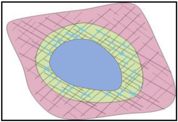 | Fracture-Cavity Reservoir | Fractured reservoir |
|---|---|---|---|
| Porosity /% | 50 | 20 | 5 |
| Rock compressibility Cp/10−4 MPa−1 | Tends to 0 | 3.5 | 6.8 |
| Type of Reservoir | Well Name | Actual Oil Production | The Comprehensive Compression Coefficient is 0.001 MPa−1 | The Comprehensive Compression Coefficient is 0.00182 MPa−1 | Method of Calculation in This Paper | ||||
|---|---|---|---|---|---|---|---|---|---|
| The Oretical Oil Production | Error/% | The Oretical Oil Production | Error/% | The Oretical Oil Production | Error/% | Dynamc Reserves | |||
| Karst cave type | TH1 | 2.5 | 1.3 | 47.7 | 0.7 | 71.2 | 2.45 | 2.0 | 6.7 |
| TS1 | 1.16 | 1.7 | 47.8 | 0.9 | 18.7 | 1.13 | 2.2 | 3.8 | |
| TH2 | 0.9 | 0.9 | 3.5 | 0.5 | 46.9 | 0.86 | 4.2 | 4.9 | |
| TH3 | 4.9 | 10.6 | 100.0 | 5.8 | 19.2 | 5.02 | 2.4 | 12.4 | |
| TH4 | 1.2 | 1.7 | 42.5 | 0.9 | 21.7 | 1.21 | 0.9 | 12.1 | |
| TH5 | 2.5 | 0.5 | 81.9 | 0.2 | 90.0 | 2.53 | 1.4 | 3.4 | |
| AD1 | 1.1 | 0.5 | 53.1 | 0.3 | 74.2 | 1.22 | 10.7 | 10.3 | |
| TH6 | 1.3 | 0.5 | 60.0 | 0.3 | 78.0 | 1.26 | 3.4 | 4.5 | |
| TH7 | 2.9 | 1.2 | 58.7 | 0.7 | 77.3 | 2.79 | 3.8 | 13.6 | |
| TH8 | 1.7 | 6.3 | 100.0 | 3.5 | 100.0 | 1.72 | 1.1 | 19.8 | |
| TH9 | 0.21 | 0.3 | 34.3 | 0.2 | 26.1 | 0.22 | 2.5 | 1.7 | |
| Fracture-cavity type | TH10 | 3.67 | 4.6 | 25.3 | 2.5 | 31.1 | 3.91 | 6.6 | 9.8 |
| T1 | 0.59 | 0.9 | 57.2 | 0.5 | 13.5 | 0.60 | 1.9 | 3.0 | |
| TH11 | 1.32 | 1.1 | 18.7 | 0.6 | 55.3 | 1.33 | 0.8 | 11.2 | |
| TH12 | 1.14 | 1.4 | 18.8 | 0.7 | 34.7 | 1.19 | 4.7 | 8.7 | |
| TH13 | 1.33 | 1.1 | 19.2 | 0.6 | 55.6 | 1.33 | 0.2 | 26.4 | |
| TH14 | 0.9 | 0.6 | 28.5 | 0.4 | 60.7 | 0.89 | 1.4 | 4.9 | |
| TH15 | 1.4 | 0.3 | 77.7 | 0.2 | 87.7 | 1.54 | 1.6 | 6.3 | |
| Fractured type | TH16 | 2.69 | 2.2 | 17.3 | 1.2 | 54.5 | 2.74 | 10.6 | 42.4 |
| TH17 | 9.5 | 21.7 | 100.0 | 12.0 | 25.9 | 9.63 | 25.0 | 16.4 | |
| TH18 | 1.6 | 1.7 | 8.9 | 1.0 | 40.1 | 1.61 | 9.7 | 19.2 | |
| TH19 | 0.7 | 0.4 | 44.2 | 0.2 | 69.3 | 0.65 | 6.7 | 5.6 | |
| TH20 | 0.2 | 0.9 | 100.0 | 3.2 | 100.0 | 0.21 | 4.4 | 1.4 | |
Disclaimer/Publisher’s Note: The statements, opinions and data contained in all publications are solely those of the individual author(s) and contributor(s) and not of MDPI and/or the editor(s). MDPI and/or the editor(s) disclaim responsibility for any injury to people or property resulting from any ideas, methods, instructions or products referred to in the content. |
© 2024 by the authors. Licensee MDPI, Basel, Switzerland. This article is an open access article distributed under the terms and conditions of the Creative Commons Attribution (CC BY) license (https://creativecommons.org/licenses/by/4.0/).
Share and Cite
He, S.; Chen, B.; Yuan, F.; Wang, X.; Wang, T. Dynamic Reserve Calculation Method of Fractured-Vuggy Reservoir Based on Modified Comprehensive Compression Coefficient. Processes 2024, 12, 640. https://doi.org/10.3390/pr12040640
He S, Chen B, Yuan F, Wang X, Wang T. Dynamic Reserve Calculation Method of Fractured-Vuggy Reservoir Based on Modified Comprehensive Compression Coefficient. Processes. 2024; 12(4):640. https://doi.org/10.3390/pr12040640
Chicago/Turabian StyleHe, Shiwei, Bo Chen, Feiyu Yuan, Xingyu Wang, and Tengfei Wang. 2024. "Dynamic Reserve Calculation Method of Fractured-Vuggy Reservoir Based on Modified Comprehensive Compression Coefficient" Processes 12, no. 4: 640. https://doi.org/10.3390/pr12040640
APA StyleHe, S., Chen, B., Yuan, F., Wang, X., & Wang, T. (2024). Dynamic Reserve Calculation Method of Fractured-Vuggy Reservoir Based on Modified Comprehensive Compression Coefficient. Processes, 12(4), 640. https://doi.org/10.3390/pr12040640