Article

Exploring Vortex–Flame Interactions and Combustion Dynamics in Bluff Body-Stabilized Diffusion Flames: Effects of Incoming Flow Velocity and Oxygen Content

1
College of Power and Energy Engineering, Harbin Engineering University, Harbin 150001, China
2
Department of Mechanical Engineering, The Hong Kong Polytechnic University, Hong Kong SAR 999077, China
*
Author to whom correspondence should be addressed.
Processes 2024, 12(3), 622; https://doi.org/10.3390/pr12030622
Submission received: 1 February 2024 / Revised: 10 March 2024 / Accepted: 12 March 2024 / Published: 21 March 2024

Abstract

:
An afterburner encounters two primary features: high incoming flow velocity and low oxygen concentration in the incoming airflow, which pose substantial challenges and contribute significantly to the deterioration of combustion performance. In order to research the influence of oxygen content on the dynamic combustion characteristics of the afterburner under various inlet velocities, the effect of oxygen content (14–23%) on the field structure of reacting bluff body flow, flame morphology, temperature pulsation, and pressure pulsation of the afterburner at different incoming flow velocities (0.1–0.2 Ma) was investigated in this study by using a large eddy simulation method. The results show that two different instability features, BVK instability and KH instability, are observed in the separated shear layer and wake, and are influenced by changes in the O2 mass fraction and Mach number. The oxygen content and velocity affected the oscillation amplitude of the downstream flow. As the O2 mass fraction decreases, the flame oscillation amplitude increases, the OH concentration in the combustion chamber decreases, and the flame temperature decreases. Additionally, the amplitude of the temperature pulsation in the bluff body flame was primarily influenced by the temperature intensity of the flame and BVK instability. Moreover, the pressure pulsation is predominantly affected by the dynamic characteristics of the flow field behind the bluff body. When the BVK instability dominated, the primary frequency of the pressure pulsation aligned with that of the temperature pulsation. Conversely, under the dominance of the KH instability, the temperature pulsation did not exhibit a distinct main frequency. At present, the influence of oxygen content and incoming flow rate on the combustion performance of the combustion chamber is not clear. The study of the effect of oxygen content on the combustion characteristics of the combustion chamber at different incoming flow rates provides a reference for improving the performance of the combustion chamber and enhancing the combustion stability.

1. Introduction

The afterburner is a critical component for thrust augmentation in military aircraft engines [1], enabling a substantial increase in the engine thrust from 60% to 70%. The airflow entering the afterburner is the exhaust gas from the main combustor in the aero-engine, which contains one-quarter less oxygen than pure air. Low oxygen content is detrimental to stable combustion [2,3,4,5], significantly reducing the combustion reaction rate and flame propagation speed in the afterburner [6,7,8]. Moreover, the incoming flow velocity in the afterburner is exceptionally high, and minor perturbations can potentially lead to combustion instability [9,10,11,12,13]. Combustion instability manifests as periodic pressure and temperature pulsations [14,15,16], posing a risk of severe mechanical vibration and localized overheating of the aero-engine. This can damage key components of the afterburner, thereby affecting the overall engine combustion performance [17,18,19,20]. Therefore, it is of great significance to explore the influence of the O2 mass fraction on the dynamic characteristics of afterburner flames under various incoming flow velocities.
Given the substantial impact of the incoming flow conditions on bluff body flames, numerous studies have investigated the phenomenon of combustion instability in bluff body flames. Hosseini et al. [21] analysed the influence of the O2 volume fraction on the combustion performances of micro-flameless combustion through numerical simulations. Their findings revealed a decrease in both the maximum and exit temperatures of the bluff body micro-flameless combustion as the O2 volume fraction decreased from 7% to 5%. Noor et al. [22] examined the influence of the O2 mole fraction on the flameless combustion performances of a bluff body. They found that decreased oxygen content resulted in a more uniform temperature distribution within the combustion chamber. Liu et al. [23] studied bluff body flame characteristics under low-oxygen-content conditions. The results indicated that the temperature and OH concentration in the reaction zone decreased at lower oxygen contents, suggesting weaker reactivity in the reaction zone. Roy et al. [24] analysed the influence of diluent addition on bluff flames using numerical simulation methods. The temperature of the flame reduced as the oxygen content decreased, and an increase in the diluent concentration and incoming flow velocity led to the flame approaching extinction. Mishra et al. [25] introduced N2 into a bluff flame and observed that a decrease in the oxygen content resulted in a decrease in the flame temperature and an increase in the length of the bluff flame. Shanbhogue et al. [26] conducted experimental research on the impact of the incoming flow velocity on premixed bluff flames. Their findings revealed that the preferential diffusion effect of the premixed bluff flames intensified with increasing velocity. Wan et al. [27] studied the influence of the incoming flow velocity on CH4/air bluff flames using numerical simulations and found that the area of the recirculation zone behind the bluff body expands with increasing incoming velocity. A high incoming flow velocity induced a high strain rate, ultimately resulting in flame extinction. Kalathoor et al. [28] investigated the impact of the incoming flow Mach number on combustion instability in an afterburner using a numerical simulation method. Their findings revealed that with an increase in the Reynolds number, the dominant frequency shifted from the acoustic mode to the hydrodynamic mode, and the length of the heat release rate zone became shorter.
Lapenna et al. [29] investigated the combustion instability of propane–air flames by experimental and numerical simulation methods, and showed that the flame is mainly affected by Darrieus–Landau (DL) instability at low Re numbers, and is gradually dominated by turbulence as the Re number increases. Emerson et al. [30] investigated the influence of the density ratio on reacting bluff body flow field characteristics. Their results indicated that as the density ratio changes, the flame morphology behind the bluff body transitions from Bénard–von Kármán (BVK) to Kelvin–Helmholtz (KH) instability. Additionally, Erickson et al. [31] studied the influence of the temperature ratio on the dynamics of bluff body-stabilized flames. Their research also demonstrated that as the temperature ratio changes, the flame transitions between BVK and KH instabilities. Deng et al. [32] used numerical simulation to study the effects of incoming temperature and oxygen content on the flame instability of a bluff, and found that the incoming temperature and oxygen content significantly affect the position of the interconversion between the KH instability and the BVK instability.
The influence of the oxygen content on the dynamic combustion characteristics of bluff body flames at different inlet velocities is not yet fully understood. To investigate how the oxygen content affects the dynamic combustion characteristics of the bluff body flame under various inlet velocities, this study utilizes the large eddy simulation (LES) method to investigate the impact of oxygen mass fraction (14~23%) on the dynamic combustion characteristics of the non-premixed bluff body flame under the Mach numbers ranging from 0.1 to 0.2, encompassing the vortex structure, flame pattern, temperature pulsation, and pressure pulsation.

2. Numerical Method

2.1. Large Eddy Simulation (LES) Model

LES directly computes large eddy and expresses small-scale eddy using a subgrid-scale (SGS) turbulence model [33,34]. The filtered LES control equations are as follows:
Continuous equation:
ρ ¯ t + ρ ¯ u ˜ i x i = 0
Momentum equation:
ρ ¯ u ˜ i t + ( ρ ¯ u ˜ i u ˜ j ) x j = ρ ¯ x i + x j ( τ ¯ i j ρ ¯ u i u j ˜ )
Energy equation:
ρ ¯ h ˜ t + ( ρ ¯ h ˜ u ˜ j ) x j = D p ¯ D t x j ( q ¯ j + ρ ¯ u j h ˜ ) + τ i j u i x j ¯ + S ¯ H + q R ¯
Component equation:
ρ ¯ Y ˜ k t + ( ρ ¯ Y ˜ k u ˜ j ) x j = x j ( V k , j Y k ¯ ρ ¯ u j Y k ˜ ) + ω ˙ k ¯
Here,  τ ¯ i j is the viscous flux,  q ¯ j is the heat flux,  h ˜ is the enthalpy flux,  Y ˜ k is the convection component flux,  τ i j is the stress tensor, and  u ˜ i j is the viscosity coefficient.
The effect of small-scale eddies on the flow field can be calculated by adding an SGS stress term [35] to the LES. The SGS stress term can be characterised by assuming the eddy viscosity as follows:
τ i j = ρ ¯ ( u i u j ˜ u ˜ i u ˜ j ) = 2 μ s g s S ˜ i j D + 2 3 ρ ¯ k δ i j
where μsgs is the SGS viscosity coefficient, and k is the SGS turbulent kinetic energy, which is defined as
ρ ¯ k = 1 2 R k k = 1 2 ρ ¯ ( u k u k ˜ u k ˜ u k ˜ )
In order to avoid the emergence of finely scaled turbulent structures in the near-wall region, the RANS solution model is used for the near-wall boundary layer [36,37]. The formula used was as follows:
μ s g s = min [ ( κ d w ) 2 , ( C S m a g Δ ) 2 ] · S { 1 exp [ ( y + / 25 ) 3 ] }
where κ = 0.41 and dw are the wall distances, S is the strain rate, y+ is the dimensionless distance near the wall, CSmag = 0.2, and ∆ is the filter size.

2.2. Discrete Phase Model

The liquid fuel was used in this study. The numerical simulation must incorporate the mass, momentum, energy, and component transfers between phases. A discrete phase model simulated the force conditions, motion, and heat transfer of fuel.
The differential equation for the force on a droplet is
d V p d t = F D ( V V p ) + ρ p ρ ρ p g + F
where  F D = 18 μ ρ p d p 2 C D Re p 24 is the droplet drag force per unit mass,  Re p = ρ d p | V p V | μ is the droplet Reynolds number, μ is the gas phase dynamic viscosity, ρ is the gas phase density, dp is the droplet diameter,  F represents other forms of force exerting on the droplets, and CD is the drag force coefficient.
The differential equation for the droplet trajectory is
d s d t = V p
This equation can be simultaneously integrated along several coordinate directions during any time step ∆t to obtain the trajectory and velocity of the droplets.
The differential equation for droplets undergoing heating or cooling (without phase transition) is
m p c p d T p d t = h A p ( T T p ) + ε p A p σ ( θ R 4 T p 4 )
where Tp and Tvap represent the droplet temperature and evaporation temperature, respectively, and mp and mp,0 represent the droplet current and initial masses, respectively.
During evaporation, the mass transfer equation is
N i = k i ( C i , s C i , )
The mass consumption by the droplet is denoted as
m p ( t + Δ t ) = m p ( t ) N i A p M ω , i Δ t
The evaporation heat transfer equation is
m p c p d T p d t = h A p ( T T p ) + d m p d t h f g + ε p A p σ ( θ R 4 T p 4 )
In the equation above, dmp/dt represents the evaporation rate.
The boiling evaporation rate is expressed as [38]
d ( d p ) d t = 2 ρ p h f g [ k ( 1 + 0.23 Re p ) d p ( T T p ) + ε p σ ( θ R 4 T p 4 ) ]
where T and Tp represent the continuous phase and liquid temperatures, respectively.

2.3. Combustion Model

A partially premixed combustion model was used to simulate the turbulent combustion in a bluff body. The mixing fraction f and process variable C were introduced as independent variables for the FGM combustion model [39]. These are expressed as follows:
f = 0.5 [ Y H Y H , o M H ] + 2 [ Y C Y C , o M C ] 0.5 [ Y H , f Y H , o M H ] + 2 [ Y C , f Y C , o M C ]
C = T T u T b T u
Here, Y indicates the mass fraction of the substance, M represents the relative atomic mass of the substance, and the subscripts 1 and 2 denote the fuel and oxidant inlets, respectively. Carbon and hydrogen are represented by the letters C and H, respectively. Only diffusion and convection affect the mixing fraction f. The transport equation is written as follows:
t ( ρ f ) + x i ( ρ u i f ) = x i ( ρ D C x i )
The control equation for the process variable C is
t ( ρ C ) + x i ( ρ u i C ) = x i ( ρ D C x i ) + ω ˙
In the two equations above, D represents the laminar diffusion coefficient and  ω · represents the reaction rate; they are expressed as follows:
ω ˙ = i n ω ˙ Y i H Y i c p , Y i ( T b T u )
Here, Yi represents the component i ω · Yi is the reaction rate of component i, HYi is the enthalpy of component i at temperature T, cp is the specific heat at constant pressure of component i at temperature T, and n represents the total number of components.
The C12H23 reaction mechanism described by Kundu et al. [40] was used to simulate the combustion reaction, replacing fuel in the model’s combustion chamber to simulate combustion.

2.4. Numerical Configuration and Boundary Conditions

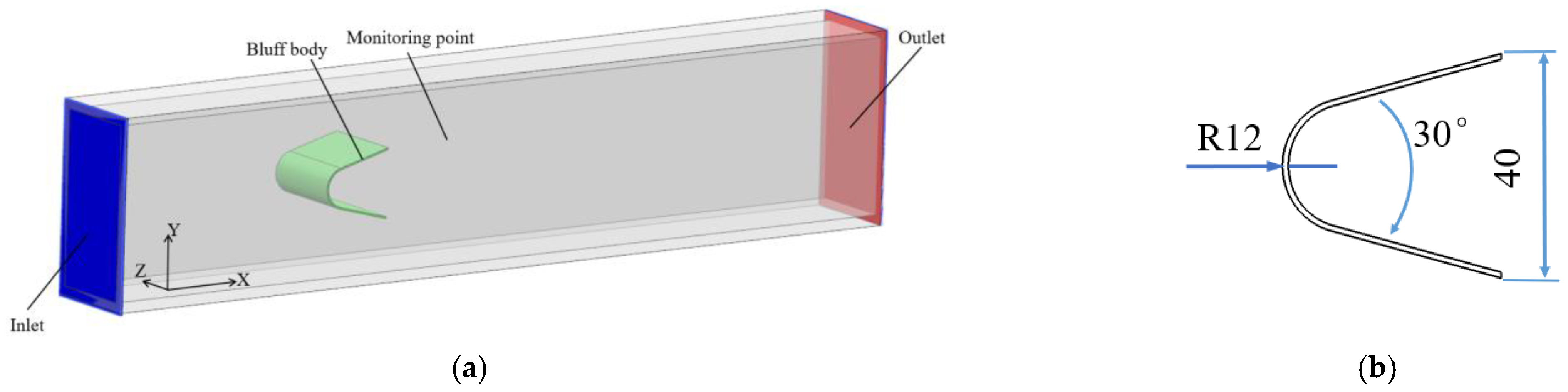
2.4.1. Model Structure
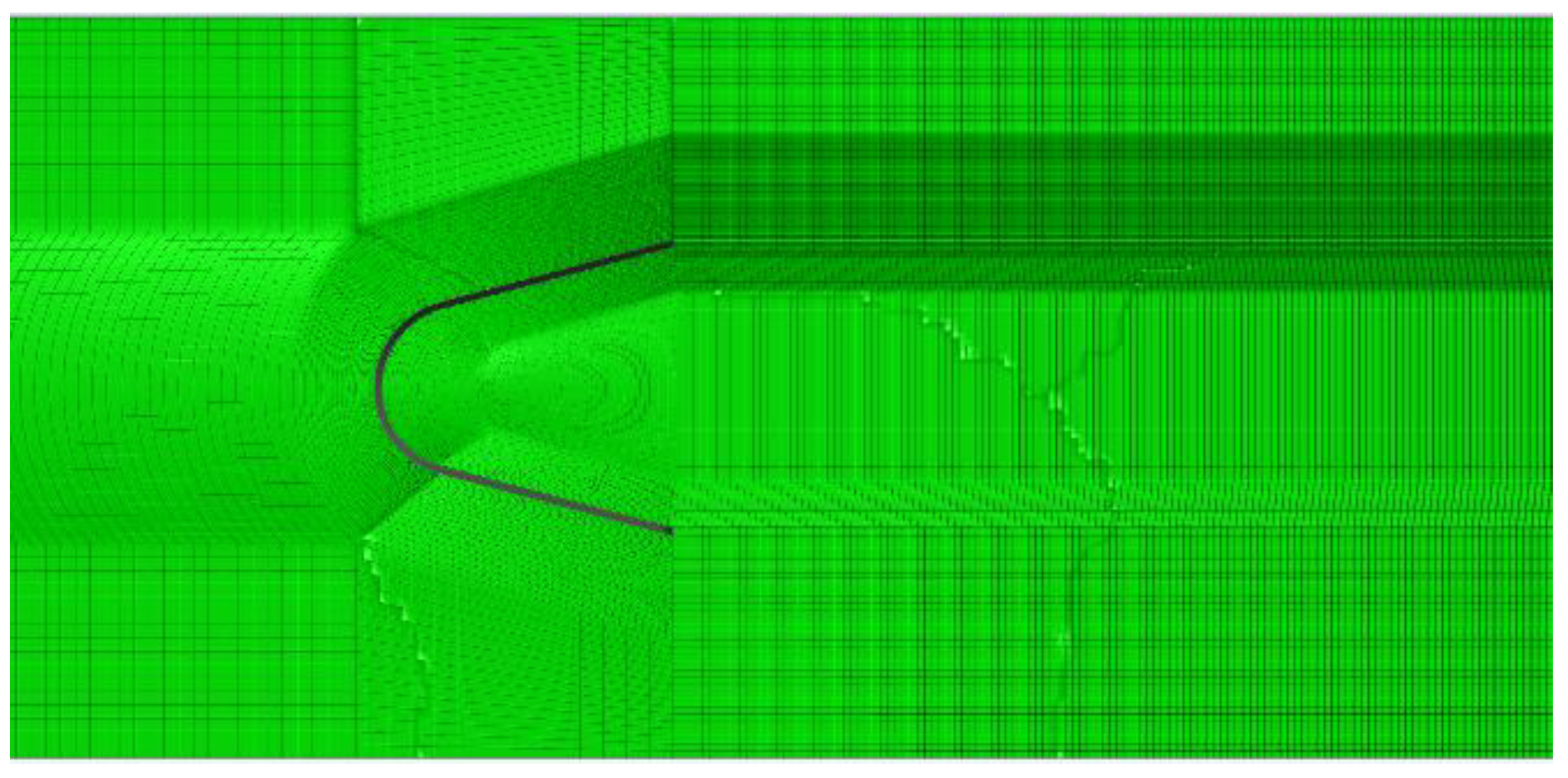
The model used for the calculations is the combustion chamber model developed by Roach et al. [41] The length of the computational domain is 1150 mm, the height is 100 mm, and the width is 50 mm. The V-shaped bluff body structure has a 30° top angle and a 40 mm wide trailing edge groove (see Figure 1).

2.4.2. Meshing

The combustor computational domain is meshed to generate a structured mesh with a mesh size of 3.4 million, and the mesh shape is polyhedral. Periodic boundary conditions are applied to the front and rear faces of the combustor. The mesh size is densified at the position of the flame stabilizer and recirculation zone. The minimum mesh size of the flame stabilizer surface in the normal direction was 0.2 mm. The number of encrypted layers is set to 10 in order to fulfil the requirements of the wall function calculation (see Figure 2).
To verify the mesh independence, the number of meshes was tested. The velocity time series in the core region of the recirculation zone behind the bluff body and in the shear layer were analysed spectrally. The spectral curves in Figure 3 reflect Kolmogorov’s −5/3 power law, indicating that the setup mesh size meets the requirements of the LES simulation [42]. Therefore, a mesh of 3.4 million nodes was chosen in this study for stable and unstable calculations.

2.4.3. Boundary Conditions

ANSYS FLUENT 14.0 was used for numerical simulations of the model combustor. Control variables were used to investigate the influence of O2 mass fraction on the performance of the bluff body at different inlet Mach numbers. The operating conditions are listed in Table 1.

2.5. Model Verification

In order to confirm the accuracy of the model, Deng et al. [32] conducted model validation under the experimental conditions in reference [43], using the same numerical model used in this study. Figure 4 compares the calculated results and experimental data for different radial positions of reactive and nonreactive flows, and the results are consistent.

3. Results

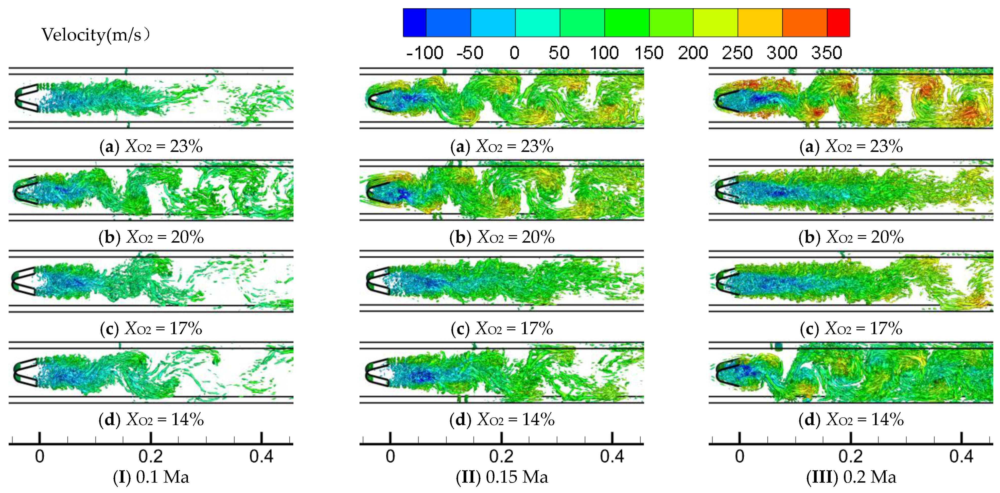
3.1. Vortex Structure

BVK instability is an absolute instability caused by asymmetric vortex shedding in the wake, and KH instability is a convective instability caused by symmetric vortex separation within the shear layer. The von Karman street is suppressed at high combustion product temperatures compared to reactant temperatures, resulting in a wake dominated by high-frequency KH instabilities. The mutual transformation between BVK instability and KH instability causes violent exothermic and large pressure gradient changes [44]. When the incoming Mach number was 0.15, under the conditions of 23% and 20% O2 mass fraction, the flow in the afterburner was characterised by BVK instability, an uneven velocity distribution in the flow field, and a large oscillation of the bluff wake. When the O2 mass fraction was decreased from 20% to 17%, the number of vortex structures in the combustion chamber was reduced, the vortex tubes on the shear layer were symmetrically distributed and approximately linear, the velocity distribution was more uniform, the BVK instability was suppressed, and the overall flow was characterised by KH instability. When the oxygen content was reduced from 17% to 14%, the shear layer still showed KH instability. However, BVK instability started to appear downstream of the combustion chamber approximately 150 mm from the trailing edge of the bluff body. It was found that during the reduction in the oxygen content from 17% to 14%, the temperature strength was weakened, the expansion vortex and oblique pressure vortex decreased more significantly relative to the viscous vortex, the vortex in the shear layer of the bluff body increased, and the BVK instability was enhanced. At an incoming Mach number of 0.2, the flow exhibited BVK instability at 23% oxygen content, and the number of vortex structures in the stabilizer decreased when the O2 mass fraction was reduced from 23% to 20%; the BVK instability was suppressed, and the vortex structures were distributed in a linear pattern. During the process of reduction in the oxygen content from 20% to 14%, the number of vortex structures inside the bluff increased. BVK instability occurred in the wake, and the area where the BVK instability occurred gradually moved upstream (see Figure 5).

3.2. Flame Structure

The variations in OH concentration and temperature distribution with oxygen content in the combustion chamber at different incoming Mach numbers are shown in Figure 6 and Figure 7, respectively. The figures show that the flame pattern was essentially the same as the vortex structure pattern. At a constant incoming flow Mach number, the OH concentration and flame temperature in the combustion chamber reduced as the O2 mass fraction reduced.
When the incoming Mach number is 0.1, under the condition of 23% oxygen content, the flame of the shear layer of the flame stabilizer is dominated by KH instability, and the flame shows a straight line. At approximately 100 mm from the downstream of the flame stabilizer, the flame is severely stretched and almost fractured, and the flame stability is poor. As the oxygen content decreased, the combustion reaction rate and flame temperature decreased significantly. When the oxygen content was 20%, there were two dynamic characteristics of KH instability and BVK instability in the flow field, and the stabilizer near-field flame still showed obvious convective instability characteristics: a symmetrical distribution of the flame in the shear layer, and a wavy shape at the interface between the flame and the external gas mixture. However, with an increase in the axial distance, the flow field is transformed into absolute instability, and the flame in the wake stream oscillates up and down, showing an S-shaped flame. When the O2 mass fraction was decreased from 20% to 17%, the flame was more zigzagged and almost broken at a position approximately 100 mm from the downstream of the bluff body, and the flame stability was further decreased. When the O2 mass fraction was decreased to 14%, the area of BVK instability moved upstream, but the flame continuity was simultaneously enhanced. When the incoming Mach number was 0.15, the flame after the stabilizer was mainly composed of swirling flames under 23% oxygen content, showing an evident vortex structure. When the O2 mass fraction was decreased from 23% to 17%, the BVK instability start position moved downstream, and the blunt body near-field flame was linear. When the O2 mass fraction further decreased to 14%, the BVK instability was enhanced, and the starting position of the flame oscillation moved upstream. When the incoming Mach number was 0.2, the flame after the stabilizer was mainly dominated by BVK instability under 23% oxygen content. When the O2 mass fraction was decreased from 23% to 20%, the BVK instability was suppressed, the flame was approximately linear and smoother, and the flame stability was improved. As the O2 mass fraction was further decreased, the BVK instability began to appear downstream of the combustion chamber, and the flame approached the extinguishing state when the O2 mass fraction was reduced to 14%.
At an oxygen content of 23%, the OH concentration and temperature in the bluff body decreased, and the main reaction zone moved downstream as the incoming Mach number increased. When the incoming Mach number was increased from 0.1 to 0.15, the near-field flame of the bluff body exhibited a large oscillation. In contrast, the BVK instability start position moved downstream as the incoming Mach number was increased to 0.2. It was found that with an increase in airflow velocity, owing to the relatively obvious increase in the viscous vortex volume, the vortex volume of the shear layer of the bluff body increases, which increases the BVK instability. In contrast, in the process of increasing the incoming Mach number from 0.15 to 0.2, owing to the weakening of the temperature strength in the bluff body, the flame temperature decreases substantially, and the BVK instability is relatively weakened. Under the conditions of 20% and 17% oxygen content, with an increase in the incoming Mach number, the OH concentration and temperature in the bluff body showed an overall increasing trend, the BVK instability was suppressed, and the flame oscillation was reduced. Under the 14% oxygen content condition, when the incoming Mach number was increased from 0.1 to 0.15, the flame temperature inside the passivate increased, and the BVK instability was suppressed. However, when the incoming Mach number was increased to 0.2, the BVK instability was enhanced. It was found that under the condition of 14% oxygen content, as the incoming Mach number was increased to 0.2, the flame was close to extinction, the expansion vortex and oblique pressure vortex decreased significantly relative to the viscous vortex, the vortex of the shear layer of the passivate body increased, and the BVK instability was enhanced.

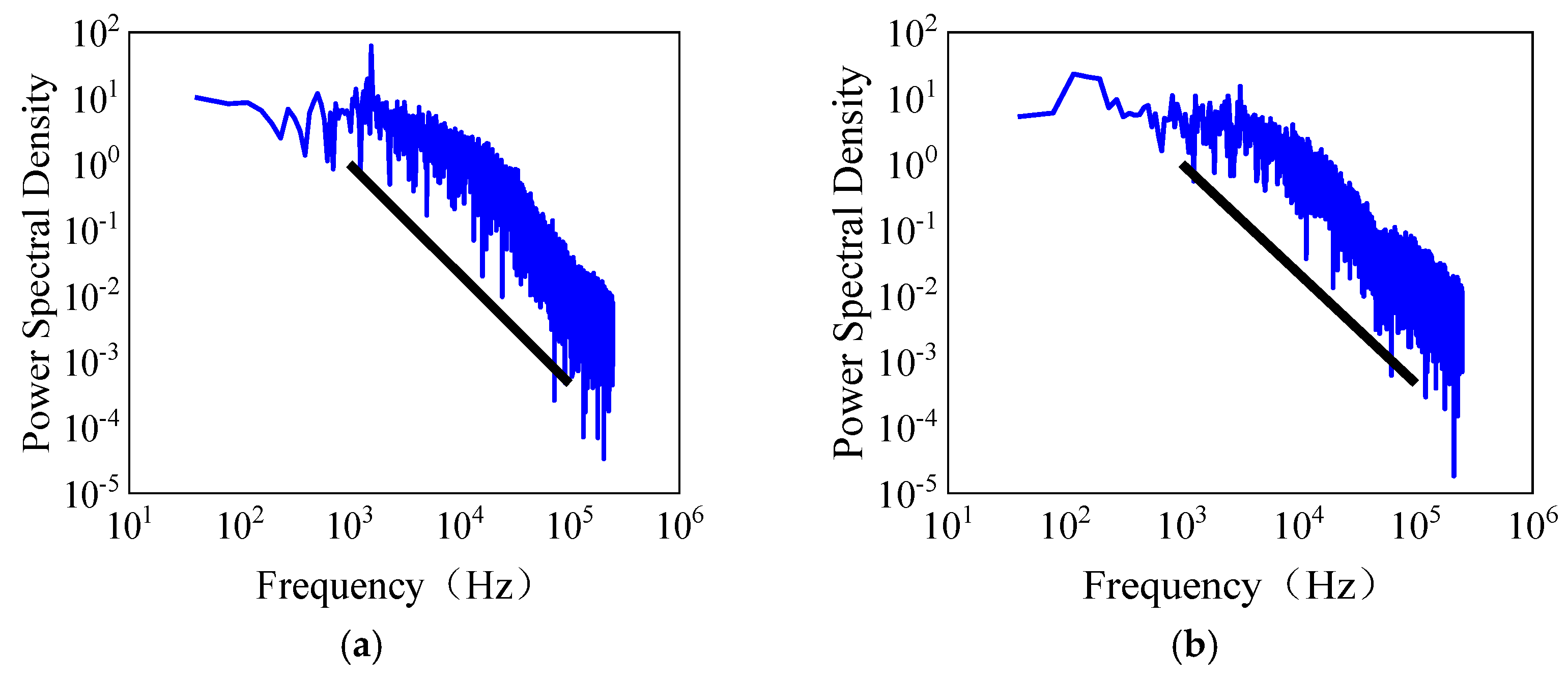
3.3. Spectral Analysis

Temperature and pressure pulsations are commonly used to monitor combustion kinetics [45,46,47] and are analysed in this section for XO2 = 14–23%, Ma = 0.1–0.2, and p = 0.1 MPa. The time domain curves of temperature and pressure pulsations were analysed for pressure and temperature pulsation data at the monitoring points using the Fast Fourier Transform (FFT) shown in Equation (20) to obtain the frequency domain information.
f ( x ) = a 0 + 1 ( a n cos n π x L + b n sin n π x L )
Due to the significant impact of the separated free shear layer on dynamic combustion characteristics, the selected monitoring point is situated at 40 mm downstream of the trailing edge of the bluff body, positioned within the recirculation zone and the mainstream area of the interface, where the pressure pulsations reach their peak intensity and exhibit the greatest amplitude.
The temperature and pressure pulsation spectra are shown in Figure 8 and Figure 9, respectively. Upon varying the incoming flow velocity and oxygen content, the reactive flow formed by the fluid as it passed through the bluff body switched between KH and BVK instabilities. When the BVK instability dominates the flow field, the pressure and temperature pulsations exhibit consistent dominant frequencies in the 750 to 1600 Hz range. This is due to the high-temperature combustion of the bluff body flame coupled with fluid dynamics. The temperature pulsation amplitude increases with increasing temperature intensity and BVK instability, and the pressure pulsation is mainly affected by the dynamic properties of the flow field behind the bluff body. The pressure pulsation amplitude increases with increasing BVK instability.
In the case of the KH instability-dominated flow field, the main frequency and amplitude of the pressure pulsation decreased, and the main frequency was in the range of 100–300 Hz. As the fluctuations in the flow field dominated by the KH instability were significantly reduced and only smaller fluctuations were generated in the downstream region, combustion was more stable and combustion exotherm was more uniform within the shear layer than in the flow field, which was mainly affected by the BVK instability. Consequently, the temperature pulsations had no obvious dominant frequency, and the frequency distribution in the spectrum was highly uniform.

4. Conclusions

This paper investigates the vortex structure, flame morphology, temperature pulsation, and pressure pulsation of a bluff body flame in the range of 14–23% oxygen content and 0.1–0.2 Ma using LES numerical simulation. The results revealed that with changes in the O2 mass fraction and Mach number, two distinct instability characteristics were observed behind the bluff body: BVK instability and KH instability. As the O2 mass fraction reduced, the flame temperature intensity decreased significantly, with a decrease in the OH concentration and temperature. As the inlet velocity increases, the viscous vortex volume increases and the vortex volume increases in the bluff body shear layer, which may lead to enhanced BVK instability. When the oxygen content decreases, the number of vortex structures decreases, the vortex tubes in the shear layer are symmetrically distributed, the velocity distribution is more uniform, and the KH instability is enhanced. However, as the oxygen content decreases, the temperature will decrease, and the expansion vortex and oblique pressure vortex decrease significantly, leading to an increase in the number of vortices in the shear layer and an enhancement of the BVK instability. The variation between BVK instability and KH instability is nonlinear with changes in oxygen content and inlet velocity under the coupled influence of inlet velocity and oxygen content. At a low Mach number (Ma = 0.1), the separated shear layer transitions from KH to BVK instability as the oxygen content decreases. As Ma ≥ 0.2, the flame and flow characteristics downstream from the flame stabilizer gradually shift from BVK instability to KH instability. In particular, the bluff body flame approached extinction at Ma = 0.2, and the oxygen content was 14%, indicating a significant challenge in achieving efficient and stable combustion in real aero-engines under high-speed and oxygen-lean conditions. Additionally, under the domination of the BVK instability, the pressure and temperature pulsation exhibited a consistent dominant frequency in the 750 to 1600 Hz range. Under the KH instability dominance, the temperature pulsation had no significant dominant frequency, and the pressure pulsation had a lower frequency of about 100–300 Hz.

Author Contributions

Conceptualization and funding acquisition, F.D.; writing—original draft preparation M.C.; methodology and investigation, M.Z.; writing—review and editing, Z.W., X.H. and H.Z. All authors have read and agreed to the published version of the manuscript.

Funding

This research was funded by the Heilongjiang Provincial Natural Science Foundation, grant number LH2020E067; the National Science and Technology Major Project, grant number 2019-III-0014-0058; the Fundamental Research Funds for the Central Universities, grant number 3072022TS0309; the Hong Kong Scholars Program; and Sichuan Science and Technology Program, grant number 2022NSFSC1912.

Data Availability Statement

The data that support the findings of this study are available from the corresponding author upon reasonable request.

Conflicts of Interest

The authors declare no conflicts of interest.

References

  1. Feng, M.; Dai, X.; Zhang, F.; Liao, G.; Jiaqiang, E. Numerical investigation on film cooling and aerodynamic performance for gas turbine endwalls with upstream vane-type and cascade-type slots. Aerosp. Sci. Technol. 2024, 145, 108857. [Google Scholar] [CrossRef]
  2. Chen, Y.; Fan, Y.; Bai, X.-S.; Xu, L.; Shan, X.; Bi, Y.; Deng, Y.; Han, Q. Experimental study on combustion and flow resistance characteristics of an afterburner with air-cooled bluff-body flameholder. Aerosp. Sci. Technol. 2022, 123, 107488. [Google Scholar] [CrossRef]
  3. Lovett, J.; Brogan, T.; Philippona, D.; Kiel, B.; Thompson, T. Development Needs for Advanced Afterburner Designs. In Proceedings of the 40th AIAA/ASME/SAE/ASEE Joint Propulsion Conference and Exhibit 2004, Fort Lauderdale, FL, USA, 11–14 July 2004; p. 4192. [Google Scholar]
  4. Safdar, M.M.; Masud, J.; Mufti, B.; Naseer, H.U.; Farooq, A.; Ullah, A. Numerical modeling and analysis of afterburner combustion of a low bypass ratio turbofan engine. In Proceedings of the AIAA Scitech 2020 Forum, Orlando, FL, USA, 6–10 January 2020; p. 628. [Google Scholar]
  5. Deng, F.; Huang, X.; Cheng, S.; Zhang, Y.; Huang, Z.; Tang, H.; Zheng, H. Experimental and modeling study of NO2 addition effects on autoignition behavior of propylene. Combust. Flame 2024, 262, 113371. [Google Scholar] [CrossRef]
  6. Hanna, M.; Bardon, M.; Rao, V. Flame stabilization behind bluff bodies. In Proceedings of the 25th Joint Propulsion Conference, Monterey, CA, USA, 12–16 July 1989; p. 2801. [Google Scholar]
  7. Zhang, X.; Chiu, H. Numerical modeling of afterburner combustion. Int. J. Turbo Jet Engines 1987, 4, 251–262. [Google Scholar] [CrossRef]
  8. Yilmaz, H. Investigation of combustion and emission performance of a micro combustor: Effects of bluff body insertion and oxygen enriched combustion conditions. Int. J. Hydrogen Energy 2019, 44, 25985–25999. [Google Scholar] [CrossRef]
  9. Wu, G.; Lu, Z.; Pan, W.; Guan, Y.; Ji, C.Z. Numerical and experimental demonstration of actively passive mitigating self-sustained thermoacoustic oscillations. Appl. Energy 2018, 222, 257–266. [Google Scholar] [CrossRef]
  10. Stöhr, M.; Yin, Z.; Meier, W. Interaction between velocity fluctuations and equivalence ratio fluctuations during thermoacoustic oscillations in a partially premixed swirl combustor. Proc. Combust. Inst. 2016, 36, 3907–3915. [Google Scholar] [CrossRef]
  11. Kheirkhah, S.; Cirtwill, J.D.M.; Saini, P.; Venkatesan, K.; Steinberg, A.M. Dynamics and mechanisms of pressure, heat release rate, and fuel spray coupling during intermittent thermoacoustic oscillations in a model aeronautical combustor at elevated pressure. Combust. Flame 2017, 185, 319–334. [Google Scholar] [CrossRef]
  12. Zhou, L.; Zhu, Q.; Ning, X.; Ai, Y.; Zhang, H. Flow Pattern-and Forces-Susceptibility to Small Attack Angles for a Rectangular Cylinder. Ocean. Eng. 2024, 300, 117376. [Google Scholar] [CrossRef]
  13. Liu, Z.; Zhou, L.; Tang, H.; Wang, Z.; Zhao, F.; Ji, X.; Zhang, H. Primary instability, sensitivity and active control of flow past two tandem circular cylinders. Ocean. Eng. 2024, 294, 116863. [Google Scholar] [CrossRef]
  14. Lieuwen, T.; Shanbhogue, S.; Khosla, S.; Smith, C. Dynamics of bluff body flames near blowoff. In Proceedings of the 45th AIAA Aerospace Sciences Meeting and Exhibit, Reno, NV, USA, 8–11 January 2007; p. 169. [Google Scholar]
  15. Ghani, A.; Poinsot, T.; Gicquel, L.; Staffelbach, G. LES of longitudinal and transverse self-excited combustion instabilities in a bluff-body stabilized turbulent premixed flame. Combust. Flame 2015, 162, 4075–4083. [Google Scholar] [CrossRef]
  16. Baraiya, N.A.; Chakravarthy, S. Syngas combustion dynamics in a bluff-body turbulent combustor. Dyn. Control Energy Syst. 2020, 239–263. [Google Scholar]
  17. Hansson, A. Combustion Instability Progress in Astronautics and Aeronautics series Vol. 222. Aeronaut. J. 2009, 113, 492–493. [Google Scholar] [CrossRef]
  18. Cohen, J.; Anderson, T. Experimental investigation of near-blowout instabilities in a lean, premixed step combustor. In Proceedings of the 34th Aerospace Sciences Meeting and Exhibit, Reno, NV, USA, 15–18 January 1996. [Google Scholar]
  19. Lieuwen, T.C.; Yang, V. Combustion Instabilities in Gas Turbine Engines: Operational Experience, Fundamental Mechanisms, and Modeling; American Institute of Aeronautics and Astronautics: Reston, VA, USA, 2006; p. 44. [Google Scholar] [CrossRef]
  20. Hobson, D.E.; Fackrell, J.E.; Hewitt, G. Combustion instabilities in industrial gas turbines—Measurements on operating plant and thermoacoustic modeling. J. Eng. Gas Turbines Power 2000, 122, 420–428. [Google Scholar] [CrossRef]
  21. Hosseini, S.E.; Wahid, M.A. Investigation of bluff-body micro-flameless combustion. Energy Convers. Manag. 2014, 88, 120–128. [Google Scholar] [CrossRef]
  22. Noor, M.; Wandel, A.P.; Yusaf, T. Numerical study of oxygen dilution and temperature distribution of biogas combustion in Bluff-body MILD burner. In Proceedings of the 7th Australian Combustion Symposium (ACS 2013), Perth, Australia, 6–8 November 2013; pp. 299–303. [Google Scholar]
  23. Liu, C.; Zhang, J.; Yang, T.; Ma, Y. Bluff-Body Flames in Hot and Diluted Environments. In Proceedings of the ASME Power Conference 2018, Lake Buena Vista, FL, USA, 24–28 June 2018; p. V001T01A002. [Google Scholar]
  24. Roy, R.N.; Sreedhara, S. A numerical study on the influence of airstream dilution and jet velocity on NO emission characteristics of CH4 and DME bluff-body flames. Fuel 2015, 142, 73–80. [Google Scholar] [CrossRef]
  25. Mishra, D.; Kumar, P. Effects of N2 gas on preheated laminar LPG jet diffusion flame. Energy Convers. Manag. 2010, 51, 2144–2149. [Google Scholar] [CrossRef]
  26. Shanbhogue, S.J.; Husain, S.; Lieuwen, T. Lean blowoff of bluff body stabilized flames: Scaling and dynamics. Prog. Energy Combust. Sci. 2009, 35, 98–120. [Google Scholar] [CrossRef]
  27. Wan, J.; Fan, A.; Yao, H.; Liu, W. Experimental investigation and numerical analysis on the blow-off limits of premixed CH4/air flames in a mesoscale bluff-body combustor. Energy 2016, 113, 193–203. [Google Scholar] [CrossRef]
  28. Kalathoor, S.; Chakravarthy, S. Multi-Scale Computational Simulation of Combustion Instability and Transition in a Model Afterburner. In Proceedings of the Turbo Expo: Power for Land, Sea, and Air 2017, Charlotte, NC, USA, 26–30 June 2017; p. V04AT04A049. [Google Scholar]
  29. Lapenna, P.E.; Troiani, G.; Lamioni, R.; Creta, F. Mitigation of Darrieus–Landau instability effects on turbulent premixed flames. Proc. Combust. Inst. 2021, 38, 2885–2892. [Google Scholar] [CrossRef]
  30. Emerson, B.; O’Connor, J.; Juniper, M.; Lieuwen, T. Density ratio effects on reacting bluff-body flow field characteristics. J. Fluid Mech. 2012, 706, 219–250. [Google Scholar] [CrossRef]
  31. Erickson, R.; Soteriou, M.; Mehta, P. The influence of temperature ratio on the dynamics of bluff body stabilized flames. In Proceedings of the 44th AIAA Aerospace Sciences Meeting and Exhibit, Reno, NV, USA, 9–12 January 2006; p. 753. [Google Scholar]
  32. Deng, F.; Zhao, M.; Qin, S.; Wang, Z.; Xie, Y.; Zheng, H.; Liu, X.; Zhang, F. Numerical Simulation Study on the Dynamics of Bluff-Body Flames under Oxygen-Lean Conditions. Energies 2023, 17, 142. [Google Scholar] [CrossRef]
  33. Jadhav, K.; Chandy, A.J. Assessment of SGS models for large eddy simulation (LES) of a stratified Taylor–Green vortex. Flow Turbul. Combust. 2021, 106, 37–60. [Google Scholar] [CrossRef]
  34. Jakirlic, S.; Saric, S.; Kniesner, B.; Kadavelil, G.; Basara, B.; Chaouat, B. SGS modelling in LES of wall-bounded flows using transport RANS models: From a zonal to a seamless hybrid LES/RANS method. In Proceedings of the Sixth International Symposium on Turbulence and Shear Flow Phenomena, Seoul, Republic of Korea, 22–24 June 2009. [Google Scholar]
  35. Wang, B.-C.; Bergstrom, D.J. A dynamic nonlinear subgrid-scale stress model. Phys. Fluids 2005, 17, 035109. [Google Scholar] [CrossRef]
  36. Davidson, L.; Peng, S.-H. Hybrid LES-RANS modelling: A one-equation SGS model combined with ak–ω model for predicting recirculating flows. Int. J. Numer. Methods Fluids 2003, 43, 1003–1018. [Google Scholar] [CrossRef]
  37. Fröhlich, J.; Von Terzi, D. Hybrid LES/RANS methods for the simulation of turbulent flows. Prog. Aerosp. Sci. 2008, 44, 349–377. [Google Scholar] [CrossRef]
  38. Kuo, K.K. Principles of Combustion; John Wiley & Sons: New York, NY, USA, 1986. [Google Scholar]
  39. Xu, L.; Zhang, Y.; Tang, Q.; Johansson, B.; Yao, M.; Bai, X.-S. LES/FGM investigation of ignition and flame structure in a gasoline partially premixed combustion engine. Proc. Combust. Inst. 2023, 39, 4851–4860. [Google Scholar] [CrossRef]
  40. Kundu, K.; Penko, P.; VanOverbeke, T. A practical kinetic mechanism for computing combustion in gas turbine engines. In Proceedings of the 35th Joint Propulsion Conference and Exhibit, Los Angeles, CA, USA, 20–24 June 1999; p. 2218. [Google Scholar]
  41. Roach, J.; Fisher, T.; Frankel, S.; Sekar, B.; Kiel, B. Cfd predictions of damköhler number fields for reduced order modeling of v-gutter flame stability. In Proceedings of the 46th AIAA Aerospace Sciences Meeting and Exhibit, Reno, NV, USA, 7–10 January 2008; p. 509. [Google Scholar]
  42. Liu, X. Study on Low Emission Combustion Chambe Design and Premixed Combustion Characteristics. Ph.D. Thesis, Harbin Engineering University, Harbin, China, 2017. [Google Scholar]
  43. George, L.K.; Raja, S.K.; Srikrishnan, A.R.; Kannan, R. The influence of the geometry of V-gutter bluff body on transient vortex shedding. Int. J. Turbo Jet-Engines 2021, 4, 40. [Google Scholar] [CrossRef]
  44. Lundrigan, J. Effect of Flame Temperature Ratio on Bluff Body Wakes. Bachelor’s Thesis, Georgia Institute of Technology, Atlanta, GA, USA, 2012. [Google Scholar]
  45. Külsheimer, C.; Büchner, H. Combustion dynamics of turbulent swirling flames. Combust. Flame 2002, 131, 70–84. [Google Scholar] [CrossRef]
  46. Li, F.; Xu, L.; Yang, L.; Cao, Z. Experimental characterization of self-excited combustion pulsation in a thermoacoustic combustor. Fuel 2023, 334, 126423. [Google Scholar] [CrossRef]
  47. Berger, F.M.; Hummel, T.; Schuermans, B.; Sattelmayer, T. Pulsation-amplitude-dependent flame dynamics of high-frequency thermoacoustic oscillations in lean-premixed gas turbine combustors. J. Eng. Gas Turbines Power 2018, 140, 041507. [Google Scholar] [CrossRef]
Figure 1. Schematic diagram of afterburner model structure. (a) Afterburner. (b) Bluff body.
Processes 12 00622 g001
Figure 2. Schematic diagram of the grid used.
Processes 12 00622 g002
Figure 3. Verification of mesh independence. (a) Location of the shear layer. (b) Core location of the recirculation zone.
Processes 12 00622 g003
Figure 4. Comparison between numerical simulation and experimental results [32]. Black dots/black square: experimental data; red line: numerical simulation results.
Processes 12 00622 g004
Figure 5. Influence of O2 mass fraction on vortex structure shedding behind bluff body under different velocities.
Processes 12 00622 g005
Figure 6. Influence of O2 mass fraction on OH concentration field under different velocities.
Processes 12 00622 g006
Figure 7. Influence of O2 mass fraction on temperature field under different velocities.
Processes 12 00622 g007
Figure 8. Changes in temperature pulsation with O2 mass fraction under various inflow velocities.
Processes 12 00622 g008
Figure 9. Changes in pressure pulsation with O2 mass fraction under various inflow velocities.
Processes 12 00622 g009
Table 1. Operating conditions to study the effect of O2 mass fraction on the combustion performance of the bluff body.
Pressure/MPaTemperature/KMach NumberOil-to-Gas RatioOxygen Content/%
Case10.19000.10.0314–23
Case20.19000.150.0314–23
Case30.19000.20.0314–23
Disclaimer/Publisher’s Note: The statements, opinions and data contained in all publications are solely those of the individual author(s) and contributor(s) and not of MDPI and/or the editor(s). MDPI and/or the editor(s) disclaim responsibility for any injury to people or property resulting from any ideas, methods, instructions or products referred to in the content.

