Article

Study on the Repair of Irregular and Deep Cracks Induced by Thermal Shock Using Al-Cu-O Reactions in Al2O3 Ceramics

1
Department of Chemical Systems Engineering, Graduate School of Engineering, Nagoya University, Furo-cho, Chikusa-ku, Nagoya 464-8601, Japan
2
Department of Materials Process Engineering, Graduate School of Engineering, Nagoya University, Furo-cho, Chikusa-ku, Nagoya 464-8601, Japan
*
Author to whom correspondence should be addressed.
Processes 2024, 12(11), 2606; https://doi.org/10.3390/pr12112606
Submission received: 28 October 2024 / Revised: 15 November 2024 / Accepted: 19 November 2024 / Published: 20 November 2024
(This article belongs to the Section Materials Processes)

Abstract

:
The irregular and deep cracks induced by thermal shock in Al2O3 ceramics were repaired by applying Cu powder layer on their surface and heating at 1200 °C under an atmosphere of air. The Al-Cu-O liquid phase formed at 1200 °C by the reaction of molten Cu, oxygen, and Al2O3 phases penetrate deep into the narrow cracks, and the precipitation phases of Cu2O and CuAlO2 densely fill the crack interior. Our observation and analysis of the filled cracks and the surrounding areas of the repaired cracks, as well as the microstructural analysis results obtained through SEM-EDS and TEM observation, suggested the aforementioned crack repair mechanism. The bending strength of the coated surface after repairing the cracks is 301.8 MPa (ΔT = 300 °C), which is twice as strong as the specimen after thermal shock and 10% higher than the original strength of the base material.

1. Introduction

Alumina (Al2O3) ceramics exhibit excellent properties such as a high Young’s modulus, high hardness, a high melting point, wear resistance, heat resistance, and also cost-effectiveness compared to other ceramics, which have facilitated their widespread application [1,2,3]. Regardless of the application, once a crack appears in a ceramic material, its structural integrity is severely compromised. The concept of repairing structural defects (cracks and pores) in addition to improving toughness is an emerging approach for dramatically improving the performance and reliability of ceramic components and devices [4,5]. In studies of surface and internal defects in structural ceramic materials, reducing the size of surface defects promotes greater material stability under stress and contributes more to strength recovery than reducing the internal defects [6]. Numerous studies indicate that effective crack repair is essential for significantly enhancing strength, thermal shock resistance, and advancing ceramic processing technology [7,8]. Recent previous works about crack healing in Al2O3-based ceramics are shown in Table 1.
T. Osada et al. subjected machined alumina containing 20 vol.% SiC whiskers to various heat treatments, investigating the effects of crack healing temperature and duration on local fracture stress. Heating to 1673 K for 10 h fully healed machining-induced cracks, preventing fracture from these cracks [9]. Some other studies are summarized in Table 1; these studies often focus on cracks in Al2O3 ceramics generated by mechanical methods, such as Vickers indentation. These cracks are typically linear, with a small number of cracks and a simple structure [10,11,12,13,14]. One such study by T. K. Gupta et al. investigating thermally shocked alumina found that it regains its strength when annealed. The cracks begin to heal at 1600 °C, and the strength is restored to 95% of the original value when the annealing temperature is kept at 1700 °C for 50 min [15]. However, the study has practical issues because of the high processing temperatures and the use of grain growth and re-sintering of Al2O3. A representative example of research on repairing deep cracks is a study by M. C. Chu et al.,who introduced 2.5 mm cracks in a bent specimen via Vickers indentation and subsequent bridge loading and then infiltrated these cracks with silica glass at 1500 °C under capillary pressure. Under these conditions, the cracks in alumina ceramics were completely filled and regained the original strength of the processed samples. Furthermore, the repaired cracks exhibited significantly greater strength than the alumina matrix, demonstrating the enhanced reliability of the alumina components [16]. These studies report methods of improving the strength and reliability of Al2O3, but the cracks they target are single, linear cracks, and very few studies have performed crack repairs on a large number of deep defects with complex geometries, such as those that occur in actual-use environments. The concept of additive selection in conventional crack repair research has focused on reactivity with atmospheric oxygen, as shown in Table 1. In order to repair more numerous and complex cracks, it is considered important to select materials focusing not only on reactivity with atmospheric oxygen but also on reactivity with the base metal Al2O3. Therefore, we focused on Al-Cu-O reactions, which have good reactivity with Al2O3 at a temperature of about 1000 °C and is used for bonding Al2O3 ceramics.
Table 1. Previous research about repairing cracks in Al2O3 based ceramics.
MaterialsCrack GenerationCrack Length (μm)Reference No.
Al2O3/15vol%SiCVickers indentation~100[9]
Al2O3/SiCw/TiSi2Vickers indentation150~500[10]
Si3N4/SiCwVickers indentation200~1200[11]
Al2O3/TiVickers indentation~80[13]
Al2O3/Ti2AlCVickers indentation~20[14]
Al2O3Thermal shock-[15]
Al2O3/Silica glassVickers indentation and bridge loading2500[16]
Y. Yoshino et al. subjected joints of copper eutectic material bonded to alumina to deoxidation and reoxidation under atmospheres with varying oxygen potentials. The bonding strength changed reversibly with interfacial oxygen concentration, revealing a critical oxygen concentration below which bonding strength did not increase, emphasizing the role of oxygen and eutectic reactions [17]. Additionally, Y. Yoshino et al. also stated that oxygen in Cu plays a crucial role in enhancing the wettability of copper on alumina. Thermodynamic considerations incorporating XPS data from the interface suggested CuAlO2 as the reaction phase and discussed changes in peel strength related to the stability of CuAlO2 and oxygen at the interface [18]. The results of interfacial structures and strength relationships show the presence of an extremely thin (about 5 nm) reaction phase in the bonded state; TEM contrast shows the characteristics of an amorphous phase, and the XPS data obtained from the interface are in good agreement with the data from standard CuAlO2 [19]. F. Moulla et al. used XRD microanalysis and Raman spectroscopy to examine the structure of the Cu-Al2O3 interface. The material was annealed at 1150 °C for three days to expand the interactional zone [20,21]. The analyses of these studies revealed a complex interactional zone at the Cu-Al2O3 interface, mainly consisting of a CuAlO2 crystalline layer, with a small amount of spinel CuAl2O4 [22,23,24]. Additionally, dendritic Cu2O structures were identified in the initial metal region [25,26].
In other applications utilizing copper–alumina reactions, X. Zhou et al. proposed using copper encapsulated within alumina spherical shells as high-temperature latent heat storage materials. By sealing copper beads within alumina shells through rapid atmospheric heating, they demonstrated that the internal state remained unoxidized even after maintaining a temperature of 1100 °C for 1000 h in the atmosphere, proving good performance as a heat storage material. The authors successfully showed that securely bonding the encapsulated part exposed to the atmosphere through copper–oxygen–alumina reactions could prevent internal oxygen supply, allowing copper to stably bond with alumina even upon melting [27,28]. F. Bao et al. reported that applying copper to high-porosity, low-strength alumina bulk produced via water stabilization and heating it in the atmosphere resulted in copper infiltration into the pores and reactions with alumina, significantly improving its strength [29].
As noted, most studies on crack repair in Al2O3 ceramics focus on cracks induced via Vickers indentation or repairs conducted at high temperatures. Furthermore, some studies have demonstrated that the reaction between copper and alumina in an oxygen-rich environment plays a crucial role in enhancing strength. However, there is no research on the repair of thermally shocked Al2O3 with deep, irregular, and widely spreading cracks by using Al-Cu-O reactions.
Therefore, the purpose of this study is to repair the irregular and deep cracks induced by thermal shock in Al2O3 ceramics by using Al-Cu-O reactions. Crack depth and residual strength were varied according to thermal shock conditions to evaluate the effect of crack repair by Al-Cu-O reactions on strength recovery. Additionally, the mechanisms underlying the penetration and filling of the cracks were investigated by analyzing the internal and interface structure of the repaired cracks through TEM observation and evaluation.

2. Experimental Procedure

2.1. Preparation of Specimen

Sintered Al2O3 plates with a relative density of 99% and a size of 30 × 40 × 5 mm were obtained via slip-casting and sintered at 1550 °C for 1 h. These plates are processed into specimens with dimensions of 3 × 4 × 40 mm for bending strength tests, in accordance with JIS R1601 [30]. First, to investigate the conditions that would cause microscopic cracks to form in the sintered Al2O3 due to thermal shock, one to three samples were placed in a Si3N4 cylinder and heated to target temperatures (Tf) in a furnace at a rate of 10 °C/min and held at their target temperatures for 30 min. The target temperatures (Tf) were set at 25, 125, 225, 275, 325, 375, 425, 475, and 525 °C. The samples were then rapidly quenched in water (Tw) at 25 °C. The rapid cooling temperature difference ΔT was defined as ΔT = TfTw, and its values were set at 0, 100, 200, 250, 300, 350, 400, 450, and 500 °C. Residual strength was measured by the four-point bending method after drying at 120 °C for 1 h, and then, the critical value of ΔT was determined by the change in residual strength. The residual strength measured by the four-point bending method after drying showed sharp decreases, with the critical ΔT determined to be 250 °C, indicating that ΔT values exceeding 250 °C result in the formation of fine cracks in the Al2O3 due to thermal shock.
Based on the above experiment, to introduce cracks into the sintered Al2O3 specimens, the specimens were heated to 325, 525, and 725 °C in air, respectively, and then quenched in water at 25 °C. Five samples were tested for each temperature condition. The quenched specimens were then completely dried at 120 °C for 1 h and cooled down in air.
Copper (Cu) paste, composed of a 2:1 mixture by weight of Cu powder (CU-114111; particle size: −200 mesh, 99.8%, Niraco Co.,Ltd, Tokyo, Japan) and a 1 wt.% CMC (Carboxymethyl cellulose) aqueous solution, was prepared.
The prepared copper paste was applied to the top surface of the Al2O3 specimens that had been previously quenched in water to induce microcracks, as aforementioned, then dried and heat-treated in an atmospheric furnace (FT-105(FM), Full-Tech, Osaka, Japan) with a temperature increase rate of 10 °C/min to 1200 °C, followed by a 1 h holding time. Subsequently, Cu-Al2O3 composite materials were prepared.

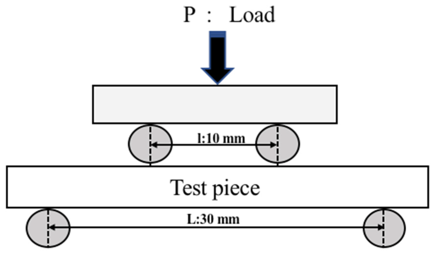
2.2. Evaluation Method

A four-point bending test was conducted in accordance with JIS R1601 [30]. Figure 1 presents a conceptual diagram of the four-point bending test; the maximum load at the specimen’s fracture is denoted as P, with the distance between the external supports (L) set to 30 mm, the distance between internal supports (l) set to 10 mm, and a crosshead speed set to 0.5 mm/min.
After removing the excess CuO, the specimen was polished to the same thickness as the original Al2O3 specimen. The specimen was then used to measure the four-point bending strength of both the coated surface and the opposite side. The bending strength of the coated surface is measured with the coated side facing down, while the opposite side is measured with the coated side facing up. After heat treatment, the samples were polished using a cross-section polisher (CP) (SM-09010, JEOL Ltd., Tokyo, Japan). The microstructure and composition of the specimens were evaluated using a field-emission scanning electron microscope (FE-SEM) (SU8230, HITACHI, Tokyo, Japan) and a Super-X energy-dispersive X-ray analyzer (EMAX Evolution X-Max 150, FEI Co., Ltd., Tokyo, Japan). X-ray diffraction (XRD) analysis (Ultima IV, Rigaku, Tokyo, Japan) was employed for phase identification, and the target used was a copper (Cu) X-ray tube, which had a wavelength of Cu Kα, which is about 1.5406 Å.
To further observe and analyze the filled crack and the surrounding area of the repaired cracks, the sample for TEM observation was prepared using an FIB system (FB-2000A, Hitachi High-Technologies Corporation, Tokyo, Japan) and FIB-SEM system (Nova200, FEI Co., Ltd., Tokyo, Japan) with a liquid Ga ion source and an accelerating voltage of 30 kV. And to protect the top surface of the sample, a carbon film and a tungsten film were coated with FIB, and then, a small piece of the sample was extracted via FIB microsampling. The small piece extracted was then thinned via FIB processing to a thickness that could be observed with a FE-TEM (Talos F200X, FEI Co., Ltd., Tokyo, Japan); the accelerating voltage was 200 kV, and the acceptance angles were HAADF: 59-200 mrad.

3. Results and Discussion

3.1. Crack Formation After Thermal Shock

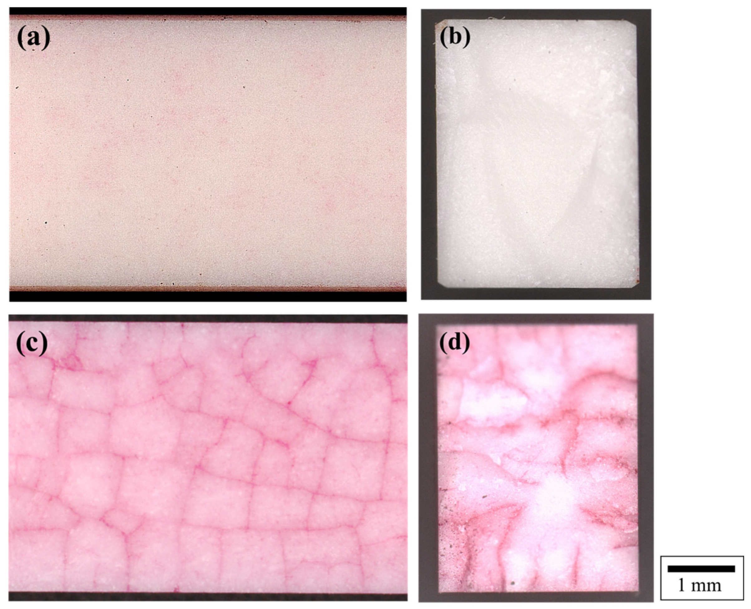
3.1.1. Cracks Pattern Appeared on the Surface of the Quenched Al2O3

Figure 2 shows optical microscope images of the Al2O3 sample stained with red ink before and after thermal shock. As seen in Figure 2a,b, the red ink remains only slightly on the surface and does not stain the interior of the Al2O3 sample, indicating that the Al2O3 sample before thermal shock treatment has only slight cracks on the surface. After heating to 325 °C and rapidly cooling in water at 25 °C (ΔT = 300 °C), as shown in Figure 2c,d, many cracks appear on the surface of the Al2O3 specimen, visualized through the use of infiltrating red ink. It can be seen that there are many irregular and widely spreading cracks on the surface of the sample in Figure 2c, and from the cross-sectional surface in Figure 2d, it can also be seen that there are cracks with a depth of about 2 mm that are widely distributed. Thus, it can be seen that the defects introduced by thermal shock are deeper, are more complex, and have a larger number of cracks in the network than those introduced via Vickers indentation.

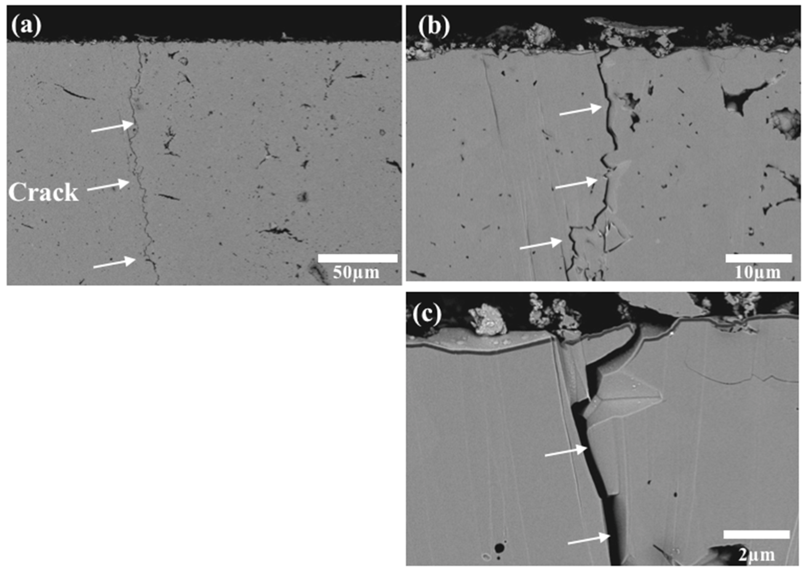
3.1.2. Microstructure and Cracks Extending in Al2O3 After Thermal Shock

Figure 3 shows an SEM image of the cross-sectional microstructure of an Al2O3 specimen. Figure 3a shows a large number of cracks introduced by thermal shock. Upon magnification, as shown in Figure 3b,c, different shapes and sizes of elongated and curved cracks are observed, whose depth is at least 200 µm and whose width is about 1 µm, and the narrow cracks seem to extend in a curved pattern.

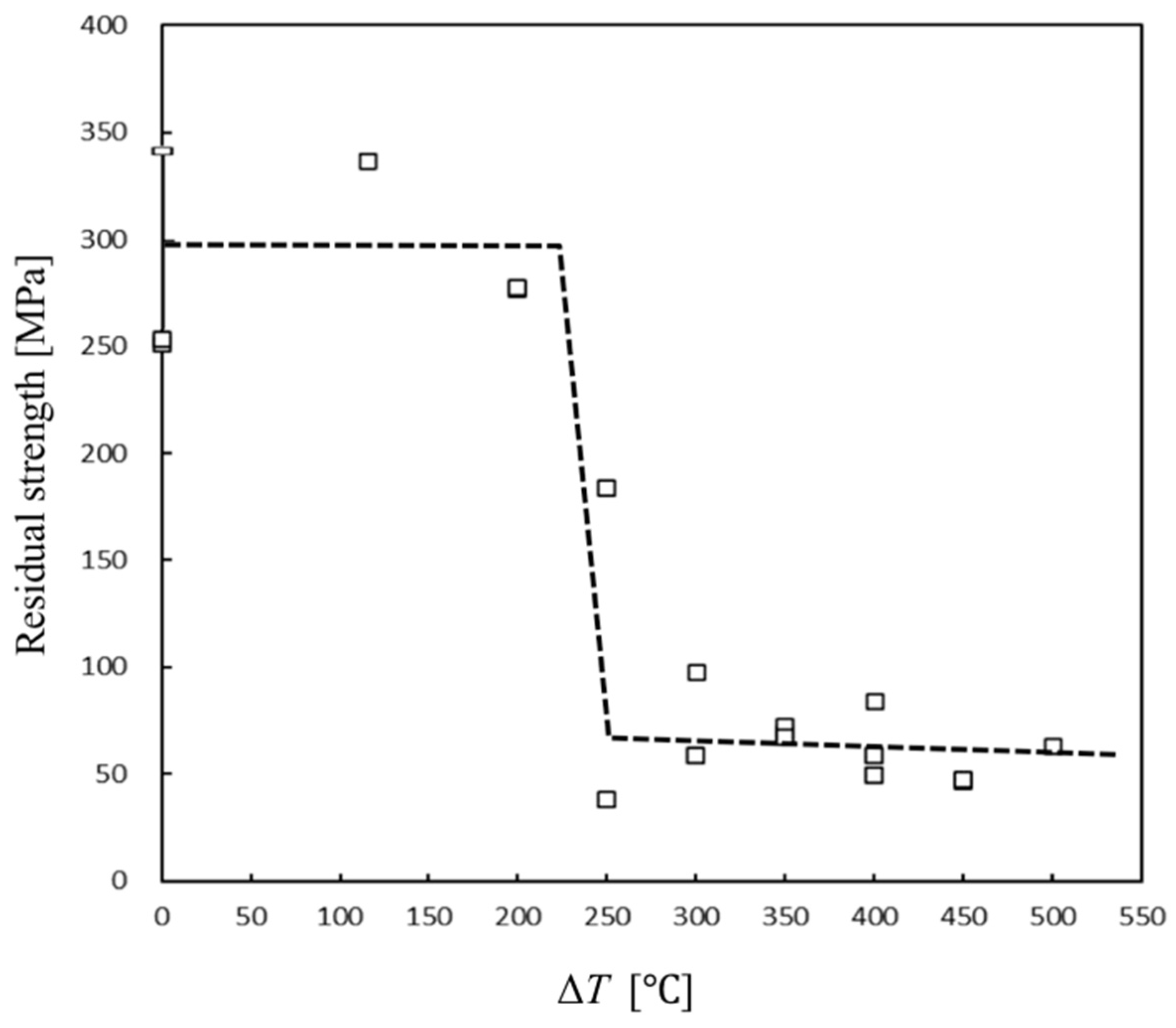
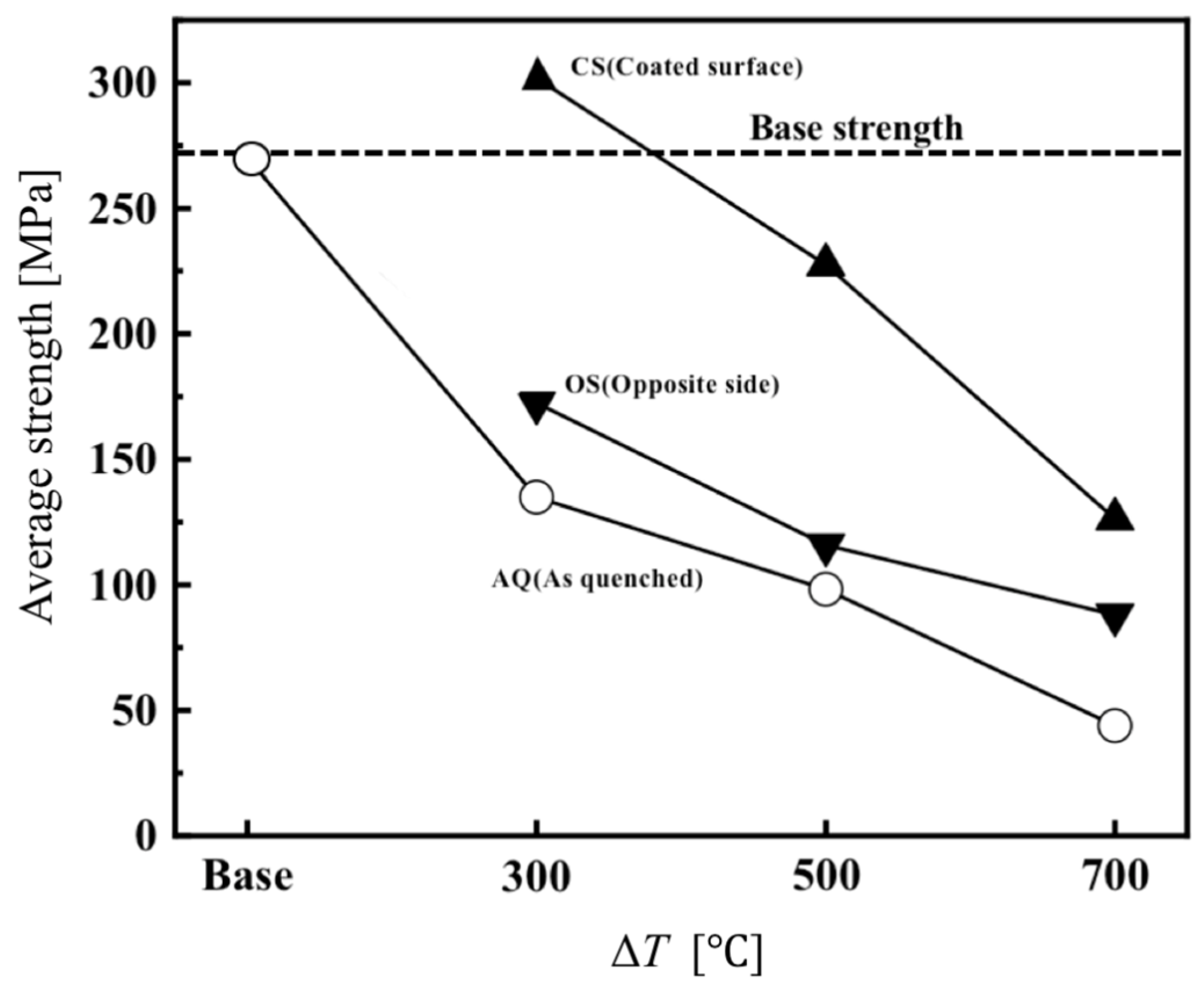
3.1.3. Determination of Thermal Shock Temperature for Crack Introduction: Residual Strength Test Results After Quenching at Different ΔT

Figure 4 shows the residual strength of Al2O3 at varying temperature differences (ΔT) and identifies the conditions that induce cracks. The results indicate significant variation in residual strength with ΔT. When the critical ΔT surpasses 250 °C, residual strength sharply decreases to approximately one-fifth of its original value. Based on these results, temperature differences (ΔT) of 300, 500, and 700 °C were selected as crack-inducing conditions.

3.2. Microstructure of Sintered Al2O3 Samples Not Subjected to Thermal Shock After Heat Treatment at 1200 °C for 1 h Following Cu Pasting

Figure 5 presents the interface microstructure of Al2O3 specimens without thermal shock, following heating at 1200 °C for 1 h with a Cu coating. Figure 5a shows the Cu on the surface is also oxidized to CuO and remains on the surface. In the interface of the Al2O3 and CuO layers in Figure 5b,c, the dark-gray area is considered to be composite oxide of Cu and Al, approximately 100 µm in length, extending diagonally from the interface into the Cu side without penetrating into the Al2O3 side. The results suggest that the reaction between Cu and the dense Al2O3 occurs only on the surface; Cu does not penetrate into the dense Al2O3.

3.3. Strength After Thermal Shock Followed by Cu Application and Heat Treatment

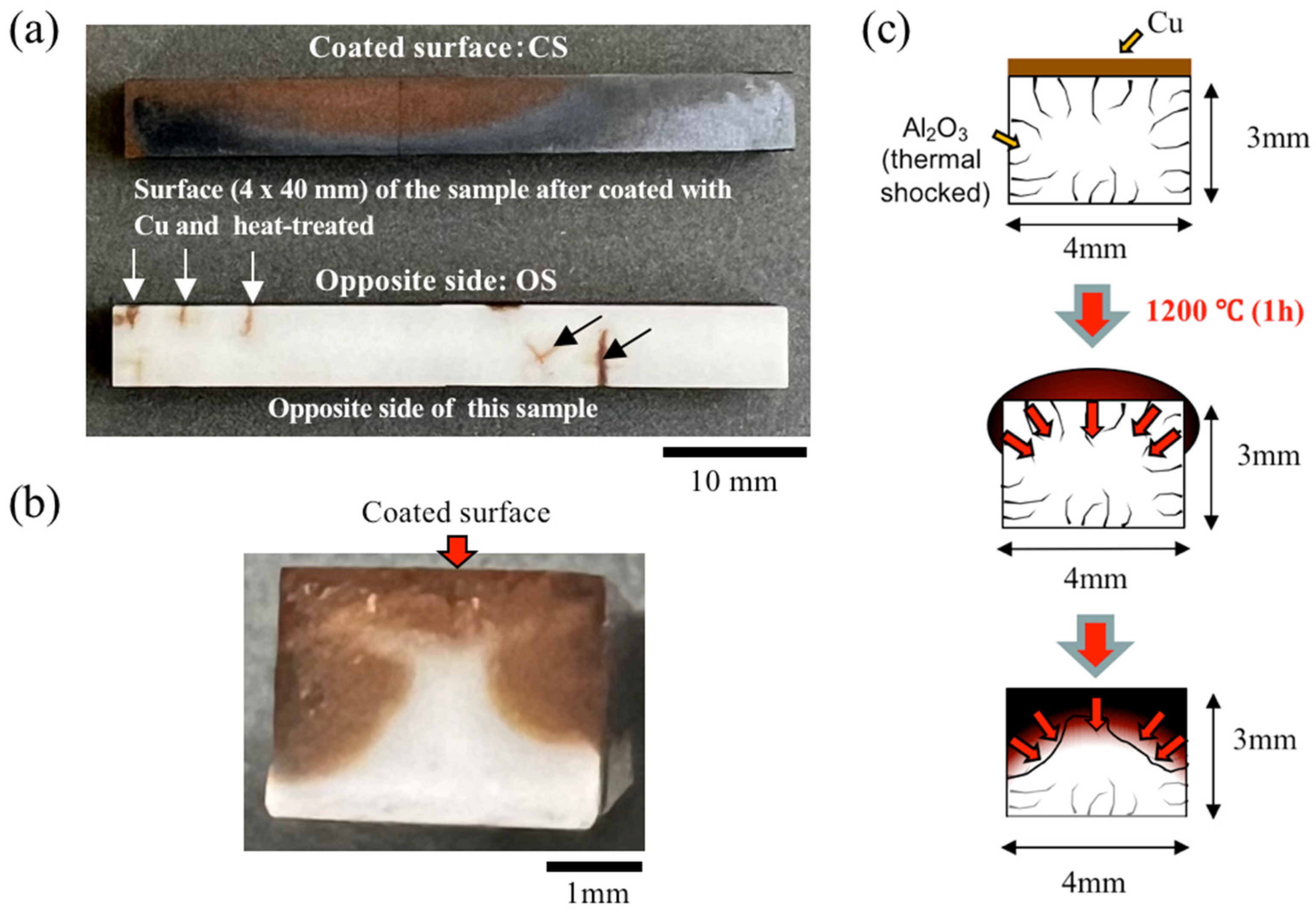
3.3.1. Low-Magnification Images of the Surface and Cross-Sectional Structure of a Sample Coated with Cu Paste Exclusively on the Upper Surface

Figure 6a shows the appearance of the coating and opposite surfaces of the Al2O3 specimen subjected to thermal shock (ΔT = 500 °C) after heating at 1200 °C and a schematic of the penetration mechanism during heating. The coating surface (CS) was black due to copper oxide precipitation, and the cross-sectional image in Figure 6b confirmed the wetting spread to the sides of the Al2O3 specimen and the penetration of copper oxide into the interior of the specimen. On the other hand, on the opposite surface (OS), copper oxide precipitation was not observed in most of the areas, but it was observed to penetrate only the cracks. This may be due to the fact that the copper powder layer that existed on the CS before heating turned into the liquid phase during melting, thus wetting and spreading to the side surface and penetrating into the cracks generated by the thermal shock by capillary force as shown in Figure 6c.

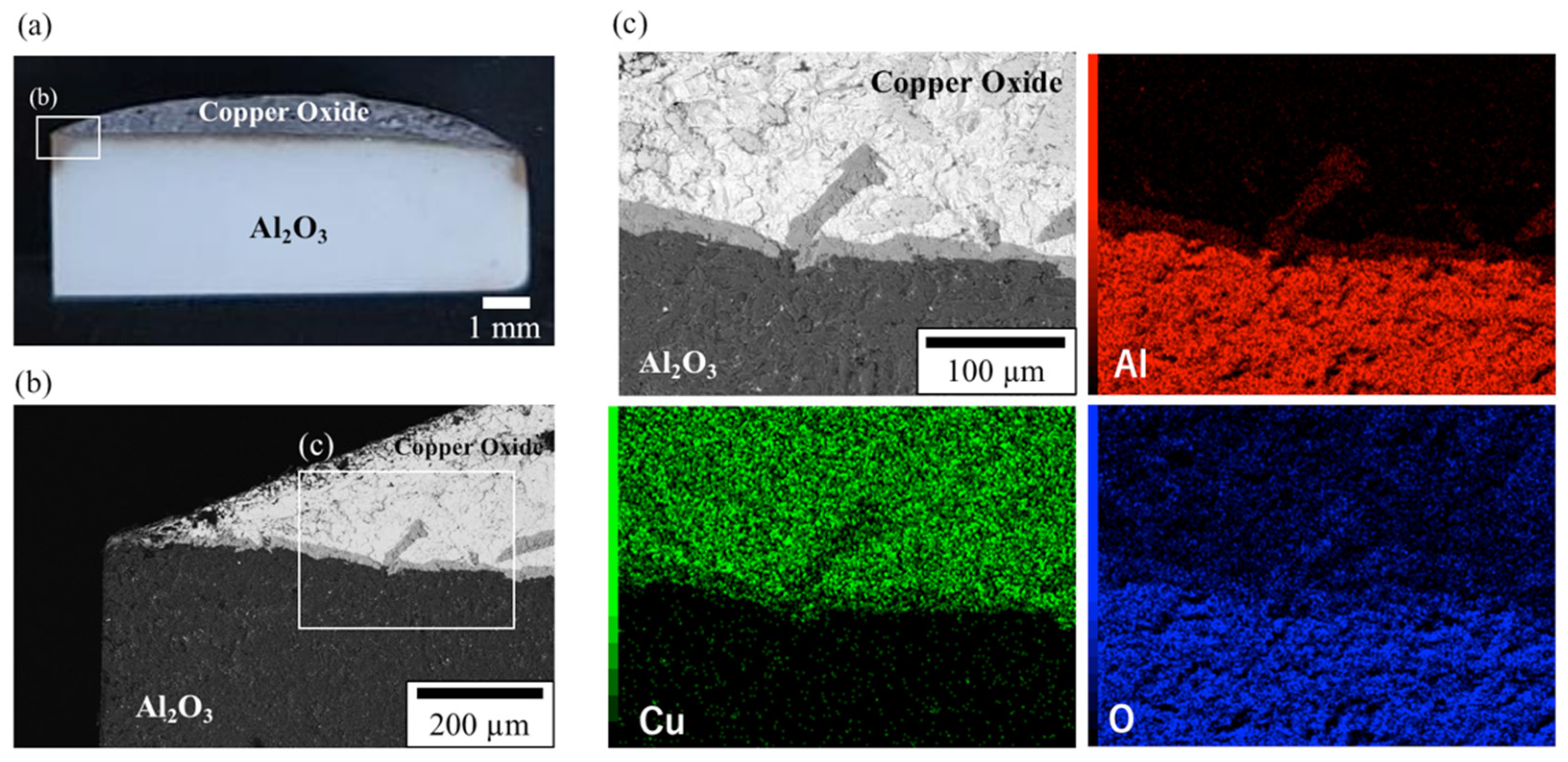
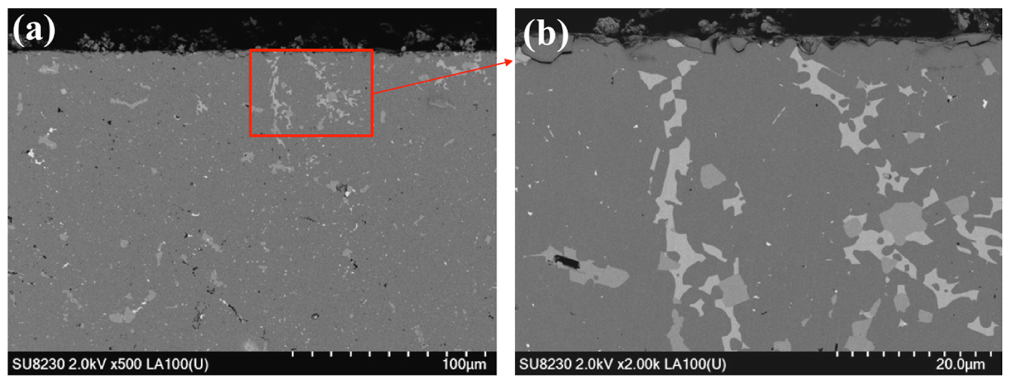
3.3.2. SEM Results of the Cross-Sectional Microstructure of a Sample Heat-Treated with Cu at 1200 °C for 1 h in Air

Figure 7 shows the SEM results of the cross-sectional microstructure of Al2O3 specimens subjected to thermal shock (ΔT = 500 °C) after heating at 1200 °C for 1 h. Deep inside the Al2O3 sample, areas of contrast different from Al2O3 were observed, suggesting that the molten Cu penetrated through the cracks in Al2O3. Furthermore, it was confirmed that the inside of the Al2O3 cracks near the surface of the sample was completely sealed and densified by precipitates. In addition, it can be seen that the deep and complex cracks caused by thermal shock are filled to the full with precipitates. Crack repair using Cu-A-O reactions is considered to be more effective for repairing complex cracks than conventional methods using composites with dispersed non-oxide or metal particles, because it can penetrate and repair only the cracked area.
Figure 8 presents the types of constituent phases in each section estimated from the EDX results. The darkest-gray area, corresponding to EDX analysis point B and constituting the majority of the image, is presumed to be Al2O3. The light-gray area near the surface (analysis point A) and slightly darker-gray areas in the middle layer (analysis point C) correspond to compounds containing Cu, Al, and O. The lighter-colored areas contain a higher ratio of Cu, while the darker areas contain more Al. Cu and O are detected in the white area (analysis point D) and are presumed to be Cu2O. Figure 9 presents the XRD patterns of the Al2O3 specimens subjected to thermal shock (ΔT = 500 °C) and heated at 1200 °C for 1 h. After the four-point bending test, the samples were cut and the reddish-brown area (3 × 4 mm surface) shown in Figure 6b was analyzed. No Cu was observed inside, and the phase α-Al2O3, Cu2O, and CuAlO2 were found to be consistent with the EDX results in Figure 8.

3.3.3. Strength of Samples Subjected to Various Treatment Conditions

Figure 10 shows the results of the average four-point bending strength of Al2O3 subjected to thermal shock at different ΔT, both before and after heating with Cu at 1200 °C for 1 h. In the four-point bending test, tensile stress was applied to water-quenched samples (AQ) and to both the coated surface (CS) and the opposite surface (OS). The average strength of the untreated Al2O3 was 274.8 MPa. After introducing cracks into the sintered Al2O3 sample, the average strength was 134.9 MPa (ΔT = 300 °C), 98.2 MPa (ΔT = 500 °C), and 43.9 MPa (ΔT = 700 °C). In contrast, after heat treatment at 1200 °C for 1 h with the Cu coating, the average strength of the coated surface was 301.8 MPa (ΔT = 300 °C), 227.5 MPa (ΔT = 500 °C), and 126.3 MPa (ΔT = 700 °C), demonstrating a clear strength recovery effect compared to the base material. The strength of the material treated on the surface opposite the coating under the same conditions was 172.4 MPa (ΔT = 300 °C), 115.9 MPa (ΔT = 500 °C), and 88 MPa (ΔT = 700 °C). Compared with the strength recovery of the coated surface, the strength recovery of the opposite side is not much. This may be because the amount of melted Cu that penetrated the opposite surface was much smaller than that of the coated surface, as shown in Figure 5, and therefore, the amount of crack repair was insufficient.

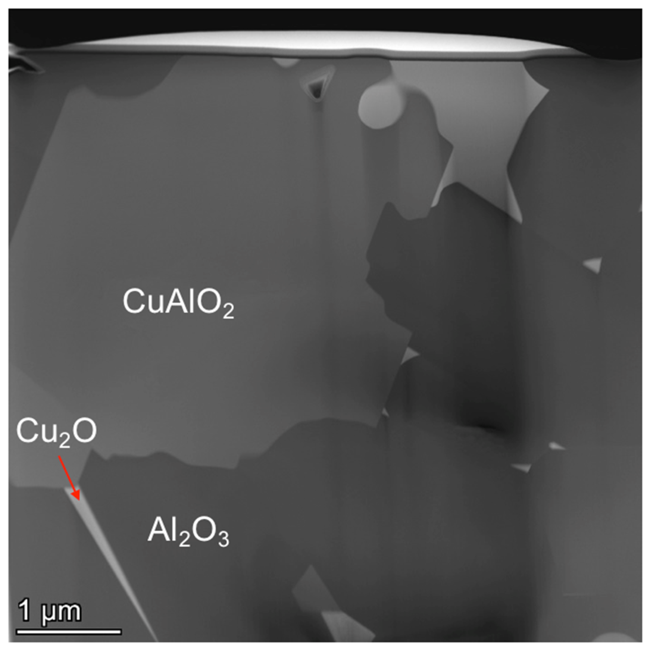
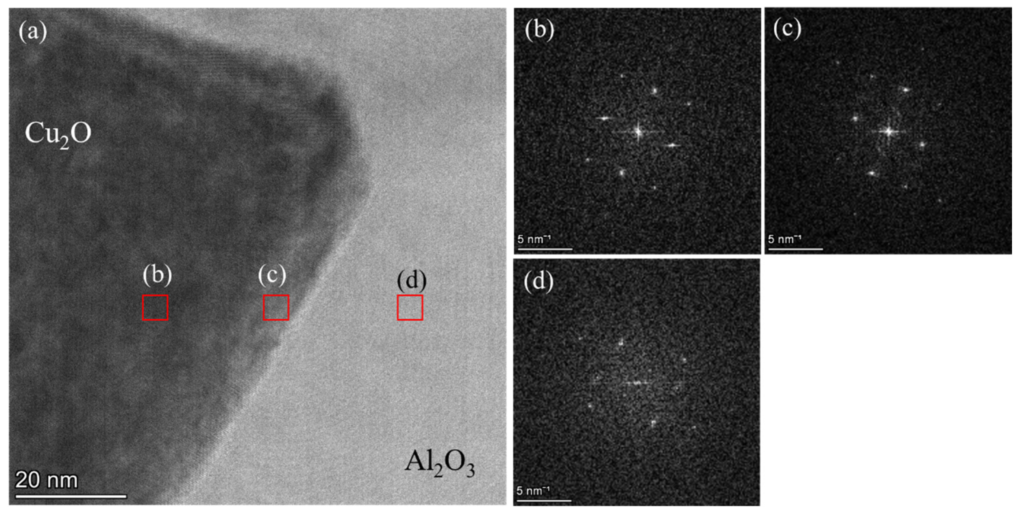
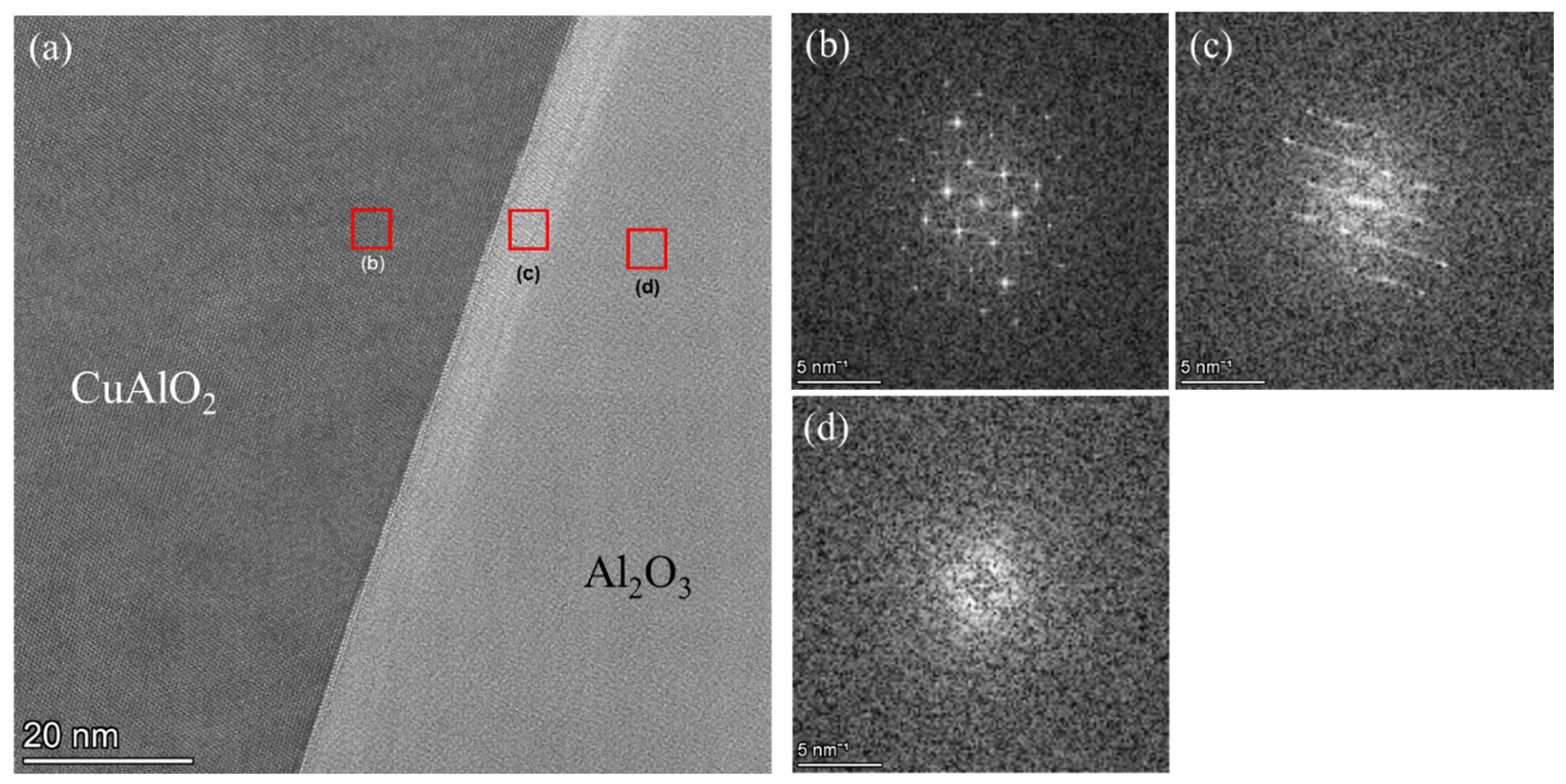
3.3.4. TEM Results of the Al2O3 and CuAlO2 Interface

Figure 11 shows an HAADF-STEM image of the cross-sectional microstructure of a sample following thermal shock. There are obvious dark (Al2O3), very dark-gray (CuAlO2), and light-gray (Cu2O) areas. It can be seen that there are clear interfaces between the three phases and no gaps in the crack, and Cu2O exists in extremely narrow cracks, so Cu is considered to have penetrated into the tiny crack tips in Al2O3 with a width less than 10 nm and filled the narrow cracks.
Figure 12 and Figure 13 show TEM images of the Cu2O-Al2O3 and CuAlO2-Al2O3 interfaces and FFT diffraction patterns. The Cu2O-Al2O3 interface does not show any reaction layer or crystalline disorder, and the FFT diffraction pattern shows a clean interface. On the other hand, at the CuAlO2-Al2O3 interface, crystalline disorder on the Al2O3 side near the interface and overlap with the CuAlO2 phase are observed in the FFT diffraction patterns. The Cu2O-Al2O3 phase diagram (Figure 14) shows that a Cu-Al-O liquid phase is formed at 1200 °C with a little dissolved Al2O3 and that the CuAlO2 phase precipitates when the dissolution concentration of Al2O3 is approximately above 7 wt% at lower temperatures. Therefore, the disorder of the crystal phase at the CuAlO2-Al2O3 interface observed via TEM is caused by dissolution from the Al2O3 grain into the liquid phase. The above suggests that the penetration of Cu into the Al2O3 cracks was accomplished by the reaction of molten Cu at high temperatures with oxygen, which further dissolved Al2O3 to form the Cu-Al-O liquid phase and penetrated into the cracks without gaps to the depth of the cracks. The penetrated Cu-Al-O liquid phase is considered to have formed a composite structure by the precipitation of Cu2O or CuAlO2, depending on the composition of the liquid phase, when the temperature decreases. The penetration of the Cu-Al-O liquid phase into the Al2O3 cracks as described above is suggested to be the reason for the strength recovery.
The microstructure and formation mechanism of the crack repair by Al-Cu-O reactions at room temperature was observed and considered as above. The microstructure and bending strength at high temperatures are thus considered to be similar to those at room temperature because the Cu compound filling the cracks is stable at temperatures not exceeding 1165 °C, according to the Cu2O-Al2O3 phase diagram. On the other hand, it is known that at temperatures above 1165 °C, a liquid phase is formed again inside the sample, but on the sample surface, the Cu2O and CuAlO2 formed react with O2 in the atmosphere at high temperatures to form CuO and CuAl2O4, which are stable at high temperature [28]. Therefore, the cracks on the sample surface are considered to remain repaired even at temperatures above 1165 °C, and the bending strength will not change significantly. Based on the above, cracks repaired using Al-Cu-O reactions are expected to have excellent stability not only at room temperature but also under an atmospheric atmosphere.

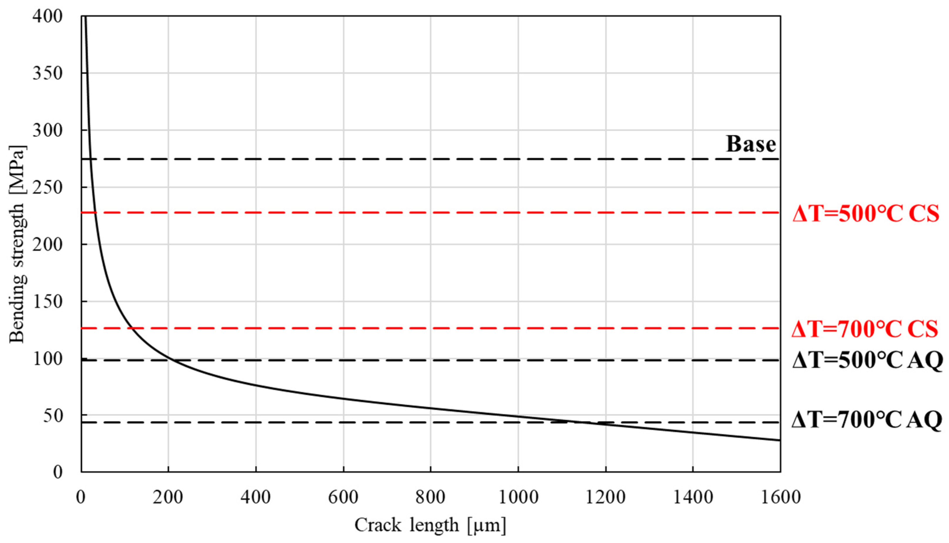
3.4. Relationship Between Different Crack Lengths and Bending Strengths

Crack length measurements for the calculation of bending strength are determined using Formulas (1)–(3). The fracture toughness, K I C , is determined as 2.5 MPa·m1/2 [32,33].
σ = 6 M b 2 ( M = P s 4 )
K Ι C = σ π a F ( a / b )
F ( a / b ) = 1.107 2.210 × ( a / b ) + 7.71 × ( a / b ) 2 13.55 × ( a / b ) 3 + 14.25 × ( a / b ) 4
Here, a is the length and b is the thickness of the specimen, respectively.
Additionally, the calculation is based on the condition that the filled part inside the crack is firmly bonded with the surrounding alumina. As shown in Figure 7 and Figure 11, there are no gaps, and it can be seen that they are firmly bonded together through the reaction.
Figure 15 shows the results of the relationship between different crack lengths and bending strengths of specimens. As the crack length increases, the strength shows a decreasing trend. The strength of Al2O3 without thermal shock is 275 MPa (Figure 10). If it is applied to Figure 15, and the crack length is estimated, it can be read as approximately 20 µm. Considering the damage caused by processes such as grinding, this value can be considered to be within a reasonable range. When the bending lengths are 98.2 and 43.9 MPa, which are the residual strengths after thermal shock of ΔT = 500 at 700 °C, the calculated crack lengths would be approximately 210 and 1180 µm, respectively. Applying the bending strength of the specimen heat-treated at 1200 °C with Cu after thermal shock (ΔT = 500 °C) to Figure 15, the crack length is estimated to be about 32 µm, which is almost the same as that of base Al2O3, indicating that almost all defects caused by thermal shock can be repaired under the same conditions. In the case of ΔT = 700 °C, after heat treatment at 1200 °C with Cu, the crack length was estimated to be about 117 µm. Almost all of the deep cracks caused by thermal shock at ΔT = 700 °C were repaired, but critical defects remained and strength recovery was insufficient. From the above, it can be concluded that crack repair in Al2O3 using Al-Cu-O reactions is a technique capable of repairing not only simple defects of a few hundred micrometers introduced by conventional Vickers indentation but also deeper, more complex defects in greater numbers.

4. Conclusions

The objective of this study is to repair, using Al-Cu-O reactions, irregular and deep cracks in Al2O3 ceramics induced by thermal shock. Additionally, it presents the use of molten copper in an oxygen-rich environment for healing alumina. The internal structure of microcracks was observed in detail through transmission electron microscopy (TEM). The results are summarized as follows:
(1) Deep and irregular cracks of more than several hundred µm introduced by thermal shock were found to be repaired via the permeation phenomenon of the Al-Cu-O liquid phase generated by Al-Cu-O reactions and by precipitates such as Cu2O and CuAlO2 formed during cooling.
(2) The Al2O3 specimens subjected to thermal shock treatment at ΔT = 500 °C and 700 °C (average bending strength: 98.2 and 43.9 MPa) recovered their strength to 227.5 and 126.3 MPa after treatment at 1200 °C for 1h with Cu coating, respectively. Particularly, the bending strength of the coated surface recovered to 301.8 MPa, which is twice as strong as the specimen (134.9 MPa, ΔT = 300 °C) after thermal shock and 10% higher than the original strength of the base material.
(3) The TEM observations and FFT diffraction patterns showed that the complex and narrow cracks of about 20 nm caused by thermal shock were densely filled without gaps, and the interface with the precipitates was clear, which was an important factor in strength recovery.
(4) The discussion using the equation relating crack length and bending strength assuming a single crack indicates that approximately 210 µm of cracks were completely repaired in the specimens heat-treated after thermal shock at ΔT = 500 °C.
(5) It can be concluded that crack repair in Al2O3 using Al-Cu-O reactions is a technique capable of repairing not only simple defects of a few hundred micrometers introduced by conventional Vickers indentation but also deeper, more complex defects in greater numbers.

Author Contributions

Conceptualization, F.B.; Methodology, F.B.; Software, S.Y.; Formal analysis, F.B.; Investigation, F.B.; Writing—original draft, F.B.; Writing—review & editing, S.Y. and H.K.; Supervision, S.Y. and H.K. All authors have read and agreed to the published version of the manuscript.

Funding

This research received no external funding.

Data Availability Statement

The original contributions presented in the study are included in the article, further inquiries can be directed to the corresponding author.

Conflicts of Interest

The authors declare no conflict of interest.

References

  1. Rajak, P.; Kalia, R.K.; Nakano, A.; Vashishta, P. Faceting, Grain Growth, and Crack Healing in Alumina. ACS Nano 2018, 12, 9005–9010. [Google Scholar] [CrossRef] [PubMed]
  2. Zocca, A.; Colombo, P.; Gomes, C.M.; Günster, J. Additive manufacturing of ceramics issues, potentialities, and opportunities. J. Am. Ceram. Soc. 2015, 98, 1983–2001. [Google Scholar] [CrossRef]
  3. Sekine, N.; Nakao, W. Advanced Self-Healing Ceramics with Controlled Degradation and Repair by Chemical Reaction. Materials 2023, 16, 6368. [Google Scholar] [CrossRef] [PubMed]
  4. Greil, P. Generic principles of crack-healing ceramics. J. Adv. Ceram. 2012, 1, 249–267. [Google Scholar] [CrossRef]
  5. Greil, P. Self-healing engineering ceramics with oxidation-induced crack repair. Adv. Eng. Mater. 2020, 22, 1901121. [Google Scholar] [CrossRef]
  6. Tseng, W.J.; Kita, H. As-fired strength of sintered silicon nitride ceramics. Ceram. Int. 2000, 26, 197–202. [Google Scholar] [CrossRef]
  7. Nakao, W.; Osada, T.; Nishiwaki, T.; Otsuka, H. Focus on self-healing materials: Recent challenges and innovations. Sci. Technol. Adv. Mater. 2021, 22, 234. [Google Scholar] [CrossRef]
  8. Pham, H.V.; Nanko, M.; Nakao, W. High-temperature Bending Strength of Self-Healing Ni/Al2O3 Nanocomposites. Int. J. Appl. Ceram. Technol. 2016, 13, 973–983. [Google Scholar] [CrossRef]
  9. Osada, T.; Nakao, W.; Takahashi, K.; Ando, K. Kinetics of self-crack-healing of alumina/silicon carbide composite including oxygen partial pressure effect. J. Am. Ceram. Soc. 2009, 92, 864–869. [Google Scholar] [CrossRef]
  10. Liu, Y.; Liu, H.; Huang, C.; Ji, L.; Wang, L.; Yuan, Y.; Liu, Q.; Han, Q. Study on crack healing performance of Al2O3/SiCw/TiSi2 new ceramic tool material. Ceram. Int. 2023, 49, 13790–13798. [Google Scholar] [CrossRef]
  11. Hu, J.F.; Deng, X.; Xu, T.Z.; Chen, Z. Experimental and theoretical investigation on the effect of crack dimension on the crack-healing performance of Si3N4/SiCw composite ceramic. Results Phys. 2019, 14, 102411. [Google Scholar] [CrossRef]
  12. Boatemaa, L.; Brouwer, J.C.; van der Zwaag, S.; Sloof, W.G. The effect of the TiC particle size on the preferred oxidation temperature for self-healing of oxide ceramic matrix materials. J. Mater. Sci. 2018, 53, 5973–5986. [Google Scholar] [CrossRef]
  13. Boatemaa, L.; van der Zwaag, S.; Sloof, W.G. Self-healing of Al2O3 containing Ti microparticles. Ceram. Int. 2018, 44, 11116–11126. [Google Scholar] [CrossRef]
  14. Boatemaa, L.; Bosch, M.; Farle, A.S.; van der Zwaag, S.; Sloof, W.G. Autonomous high-temperature healing of surface cracks in Al2O3 containing Ti2AlC particles. J Am Ceram Soc. 2018, 101, 5684–5693. [Google Scholar] [CrossRef]
  15. Gupta, T.K. Crack healing and strengthening of thermally shocked alumina. J. Am. Ceram. Soc. 1976, 59, 259–262. [Google Scholar] [CrossRef]
  16. Chu, M.C.; Cho, S.J.; Yoon, K.J.; Park, H.M. Crack Repairing in Alumina by Penetrating Glass. J. Am. Ceram. Soc. 2005, 88, 491–493. [Google Scholar] [CrossRef]
  17. Yoshino, Y. Role of Oxygen in Bonding Copper to Alumina. J. Am. Ceram. Soc. 1989, 72, 1322–1327. [Google Scholar] [CrossRef]
  18. Yoshino, Y.; Ohtsu, H. Interface Structure and Bond Strength of Copper-Bonded Alumina Substrates. J. Am. Ceram. Soc. 1991, 74, 2184–2188. [Google Scholar] [CrossRef]
  19. Yoshino, Y.; Shibata, T. Structure and Bond Strength of a Copper–Alumina Interface. J. Am. Ceram. Soc. 1992, 75, 2756–2760. [Google Scholar] [CrossRef]
  20. Moulla, F.; Chekirou, W.; Karaali, A.; Karaali, N.; Mirouh, K. Solid state synthesis and spectroscopic analysis of CuAlO2 and spinel CuAl2O4. Phase Transit. 2020, 93, 813–825. [Google Scholar] [CrossRef]
  21. Hussain, M.Z.; Khan, U.; Jangid, R.; Khan, S. Hardness and wear analysis of Cu/Al2O3 composite for application in EDM electrode. Mater. Sci. Eng. 2018, 310, 012044. [Google Scholar] [CrossRef]
  22. Sang, K.; Weng, Y.; Huang, Z.; Hui, X.; Li, H. Preparation of interpenetrating alumina–copper composites. Ceram. Int. 2016, 42, 6129–6135. [Google Scholar] [CrossRef]
  23. Hu, W.; Donat, F.; Scott, S.A.; Dennis, J.S. The interaction between CuO and Al2O3 and the reactivity of copper aluminates below 1000 °C and their implication on the use of the Cu–Al–O system for oxygen storage and production. RSC Adv. 2016, 6, 113016–113024. [Google Scholar] [CrossRef]
  24. Zhang, Y.; Liu, Z.; Feng, L.; Zang, D. Effect of oxygen partial pressure on the structure and properties of Cu–Al–O thin films. Appl. Surf. Sci. 2012, 258, 5354–5359. [Google Scholar] [CrossRef]
  25. Trinidad, C.S.; Angel, G.D.; Torres, G.T.; Uribe, A.C.; Pavón, A.A.S.; Que, Z.G.; Perez, J.C.A.; Morales, F.J.T. Effect of the CuAl2O4 and CuAlO2 Phases in Catalytic Wet Air Oxidation of ETBE and TAME using CuO/γ-Al2O3 catalysts. ChemistryOpen 2019, 8, 1143–1150. [Google Scholar] [CrossRef]
  26. Hernandez, G.C.; Hernandeza, S.M.; Tostado, E.C.; Flores, F.D.; Gonzalez, E.C.; Alonso, C.M.; Cruz, J.S. CuAlO2 and CuAl2O4 thin films obtained by stacking Cu and Al films using physical vapor deposition. Results Phys. 2018, 9, 745–752. [Google Scholar] [CrossRef]
  27. Zhou, X.; Yamashita, S.; Kubota, M.; Kita, H. Encapsulated copper-based phase-change material for high-temperature heat storage. ACS Omega 2022, 7, 5442–5452. [Google Scholar] [CrossRef]
  28. Zhou, X.; Yamashita, S.; Kubota, M.; Zhang, C.; Hong, F.; Kita, H. Macro encapsulated Cu-based phase change material for high temperature heat storage with characteristic of self-sealing and high durability. Appl. Therm. Eng. 2023, 229, 120491. [Google Scholar] [CrossRef]
  29. Bao, F.; Yamashita, S.; Daki, H.; Nakagawa, K.; Kita, H. Microstructure modification of alumina prepared by water-stabilized plasma spraying method using Al-Cu-O reaction. J. Eur. Ceram. Soc. 2024, 44, 6113–6123. [Google Scholar] [CrossRef]
  30. Japanese Industrial Standards, Testing Method for Flexural Strength (Modulus of Rupture) of Fine Ceramics at Room Temperature. JIS R 1601. 2008. Available online: https://standards.globalspec.com/std/1150428/jis-r-1601 (accessed on 20 March 2008).
  31. Misra, S.K.; Chaklader, A.C.D. The System Copper Oxide—Alumina. J. Am. Ceram. Soc. 1963, 46, 509. [Google Scholar] [CrossRef]
  32. Zmak, I.; Coric, D.; Mandic, V.; Curkovic, L. Hardness and Indentation Fracture Toughness of Slip Cast Alumina and Alumina-Zirconia Ceramics. Materials 2019, 13, 122. [Google Scholar] [CrossRef] [PubMed]
  33. Tada, H.; Paris, P.C.; Irwin, G.R. The Stress Analysis of Cracks Handbook; Elias, A.C., Ed.; ASME Press: New York, NY, USA, 2000. Available online: https://books.google.co.jp/books/about/The_Stress_Analysis_of_Cracks_Handbook.html?id=9tfAQgAACAAJ&redir_esc=y (accessed on 26 July 2000).
Figure 1. Conceptual diagram of the four-point bending test.
Processes 12 02606 g001
Figure 2. Optical microscopic images of Al2O3 specimen stained with red ink (a,b) before and (c,d) after thermal shock (ΔT = 300 °C); (a,c) 4 × 40 mm surface and (b,d) cross-sectional face.
Processes 12 02606 g002
Figure 3. Cracks observed on the cross-sectional surfaces of the Al2O3 specimens that were heat-treated at 525 °C for 30 min in air and quenched in water at 25 °C (ac). The white arrow indicates the region where cracks have formed due to thermal shock.
Processes 12 02606 g003
Figure 4. Residual strength of sintered Al2O3 under different thermal shock conditions.
Processes 12 02606 g004
Figure 5. Cross-sectional surfaces of Al2O3 specimens without thermal shock, following heating at 1200 °C for 1 h with a Cu coating (ac).
Processes 12 02606 g005
Figure 6. (a) The coated surface and opposite side of the Al2O3 specimens subjected to thermal shock (ΔT = 500 °C) after heating at 1200 °C for 1 h. The arrow points to the crack. (b) Cross-sectional surfaces of the specimens. (c) A schematic of the mechanism of Cu penetrating the Al2O3 specimen.
Processes 12 02606 g006
Figure 7. Cross-section of Al2O3 specimens subjected to thermal shock (ΔT = 500 °C) after heating at 1200 °C for 1 h (a,b).
Processes 12 02606 g007
Figure 8. Various contrasts observed in Al2O3 specimens subjected to thermal shock (ΔT = 500 °C) after heating at 1200 °C for 1 h.
Processes 12 02606 g008
Figure 9. XRD patterns of Al2O3 specimens subjected to thermal shock (ΔT = 500 °C) after heating at 1200 °C for 1 h with Cu.
Processes 12 02606 g009
Figure 10. Average four-point bending strength of Al2O3 subjected to thermal shock at different ΔT before and after heating with Cu at 1200 °C for 1 h. The dashed line represents the baseline strength of untreated Al2O3.
Processes 12 02606 g010
Figure 11. HAADF-STEM image of the cross-section of the specimen after thermal shock (ΔT = 500 °C). The red arrows represents the Cu2O region.
Processes 12 02606 g011
Figure 12. FFT diffraction patterns of (b) the Cu2O phase, (c) the Cu2O phase near the interface, and (d) the Al2O3 phase in (a) a TEM image of the Cu2O-Al2O3 interface.
Processes 12 02606 g012
Figure 13. FFT diffraction patterns of (b) the CuAlO2 phase, (c) the Al2O3 phase near the crystal interface, and (d) the Al2O3 phase in (a) a TEM image of the CuAlO2-Al2O3 interface.
Processes 12 02606 g013
Figure 14. Phase diagram of the Cu2O-Al2O3 system [31].
Processes 12 02606 g014
Figure 15. Relationship between different crack lengths and bending strengths.
Processes 12 02606 g015
Disclaimer/Publisher’s Note: The statements, opinions and data contained in all publications are solely those of the individual author(s) and contributor(s) and not of MDPI and/or the editor(s). MDPI and/or the editor(s) disclaim responsibility for any injury to people or property resulting from any ideas, methods, instructions or products referred to in the content.

