Abstract
Under the background of achieving carbon dioxide peaking and carbon neutrality, the rapid development of renewable energy power generation poses new challenges to the flexible adjustment capabilities of traditional power plants. To explore the furnace combustion stability and optimal operation modes during deep peak shaving, a simulation of the combustion process under low-load conditions for a 600 MW wall-fired boiler is performed utilizing computational fluid dynamics (CFD) analysis. The impact of burner combination modes on the combustion process within the furnace is explored at 25% and 35% boiler maximum continuous ratings (BMCRs). This study investigates two configurations of burner combinations. One mode operates burners in layers A, B, and C, which include the lower layers of burners on the front and rear walls of the boiler, as well as the middle-layer burners on the rear wall, referred to as OM1. The other mode operates burners in layers A and C, which include the lower layers of burners on the front and rear walls of the boiler, referred to as OM2. The results indicate that OM2 exhibits superior capabilities in orchestrating the distribution of the airflow velocity field and temperature field under the premise of ensuring no more than a 1% decrease in the pulverized coal burnout rate. When OM1 is employed, the airflow ejected from the middle-level burners hinders the upward movement of pulverized coal sprayed from the lower-level burners, causing a larger proportion of pulverized coal to enter the ash hopper for combustion. Consequently, the ash hopper attains a peak mole fraction of CO2 at 0.163. OM2 delays the blending of pulverized coal with air by enhancing the injection quantity of pulverized coal per burner. As a result, the generation of CO in the ash hopper reaches a notable mole fraction of up to 0.108. The decreased furnace temperature promotes the formation of fuel-based NOx during low-load operation. Taking the 25% BMCR as an example, the NOx emissions measured at the furnace outlet are 743 and 1083 ppm for OM1 and OM2, respectively. This study focuses on the impact of combustion combinations on the combustion stability when the boiler is operating at low loads. The findings could enrich previous research on combustion stability and contribute to the optimization of combustion schemes for power plant boilers operating at low loads.
1. Introduction
As China’s energy structure continues to transform and upgrade, the share of traditional thermal power generation is expected to decline, making way for a larger proportion of renewable energy sources [1]. However, owing to the inherent randomness, variability, and intermittency of solar and wind power generation, the current power plants are inadequate to meet the development demands of these renewable energy sources [2,3]. Considering coal power generation remains the main means of electricity supply in China, retrofitting current coal-fired units for greater flexibility and a deeper peak shaving capacity is a primary approach to improving the utilization of renewable energy [4,5]. The crucial factor for deep peak shaving for coal-fired units lies in enhancing the boiler’s ability to sustain steady combustion under low-load conditions, facilitate rapid start-up and shutdown, and enable quick load adjustments. As a result, addressing potential issues that may arise during low-load operation, including elevated NOx emissions, uneven furnace temperature, low steam temperature, excessive wall temperatures, and poor coal burnout, is essential [6,7,8,9]. Therefore, investigating the combustion properties of boilers during low-load operation is of paramount importance. To address the various issues faced by boilers during low-load combustion, scholars have proposed the use of a new type of burner that can maintain flame stability and inhibit the formation of NOx [10]. Some scholars have also compared the combustion characteristics of different types of power station boilers under low-load operation, which is helpful for power plants requiring variable-load operation to choose the right type of boiler [11]. Additionally, changing the operating parameters of the boiler, such as adjusting the excess air coefficient, primary air rate, and secondary air rate, is often employed to improve the combustion conditions under low-load conditions [9,12,13].
Based on the mode of combustion arrangement, coal-fired boilers, which are widely utilized in China, are typically categorized into wall-fired, tangentially fired, and down-fired boilers [14]. Several types of boilers are prevalent, notably wall-fired boilers, which are favored for their advantages such as enhanced stability during low-load combustion and reduced temperature variations in the horizontal flue gas pass [15,16,17]. Operating a boiler at 70%~100% boiler maximum continuous rating (BMCR) is generally considered optimal. When operating below this range, the boiler is referred as being under low-load conditions. In such scenarios, the boiler performance deteriorates significantly, leading to a series of issues including decreased combustion stability [18,19]. Therefore, the combustion characteristics and NOx emissions of wall-fired boilers under reduced operational loads have garnered extensive attention [20,21,22,23]. Measures such as stopping the operation of certain burners are often adopted to ensure that each burner operates within a reasonable range when the operating load of the boiler decreases. During the low-load operation of the boiler, solely relying on the upper burners could cause combustion instability, whereas employing the lower burners increases the dwell time of pulverized coal inside the furnace, which subsequently prompts its burnout [24,25,26]. As the boiler load decreases, both the fuel and airflow rates decrease. When the boiler operates at 20% to 50% BMCR, it is common to apply a method of operating two or three layers of burners located in the lower part of the furnace. Operating fewer layers of burners means that each burner sprays more coal powder, which is not conducive to the complete combustion of the coal powder. On the other hand, using more layers of burners can result in unavoidable flame skewing, which may cause excessive thermal load deviation on the water-cooled wall, potentially affecting the safe operation of the boiler [20]. The velocity of over-fire air (OFA) plays a crucial role in influencing the combustion behavior of the boiler. As evidenced by previous studies [27,28], it can profoundly reduce the generation NOx when the OFA rate is approximately 0.2 to 0.3. However, this results in an under-oxygenated combustion state for the pulverized coal in the burner area, consequently leading to the generation of CO in that region. In addition, the air sprayed by the burners is separated into the central air and inner and outer secondary air to entering the furnace, which delays the mixing of the coal powder and secondary air and increasing the generation of CO. Historically, lower demands for the peak shaving capability in power plants is required. Previous investigations [13,29,30] have often focused on work conditions above 40% BMCR and have usually applied a single-burner operation mode. As the boiler load decreased progressively, these studies have illuminated the combustion behaviors exhibited by boilers. However, foundational research [31,32] on the combustion mechanism of pulverized coal during the operation of boilers with different burner configurations at extremely low loads (especially when the boiler load falls below 40% BMCR) has still been limited.
This study employs the methodology of a computational fluid dynamics (CFD) simulation to investigate the combustion characteristics of a 600 MW supercritical wall-fired boiler operating under extreme low-load conditions. The velocities, temperatures, and component distributions of the boiler operating with different burner combinations at 25% and 35% BMCR, respectively, are explored in detail. Compared to other studies focusing on the combustion stability under a reduced boiler load, this study focuses on investigating a more reasonable operation mode for boiler operation at the same load. The findings of this research could enrich the foundational theoretical framework for the efficient operation of coal-fired power plants under conditions of peak shaving at reduced loads.
2. Numerical Model
Conducting operational experiments on boilers requires a substantial consumption of resources. CFD numerical stimulation is a way to calculate detailed velocity fields, temperature distributions, and the concentration profiles of combustion products within a boiler. The calculation results provide valuable insights and theoretical guidance for the further optimization and adjustment of the boiler. This study adopts the popular fluid simulation software Ansys Fluent (Fluent 2022 R2), which is currently applied internationally, for study.
2.1. Mathematical Models
2.1.1. Governing Equations
The process of burning coal powder encompasses intricate physical and chemical transformations that pose a significant challenge to accurate depiction [32]. To ascertain the behavior of coal powder within the furnace, the utilization of Ansys Fluent is employed for the discerning selection of suitable sub-models. The complete coal powder reaction model mainly includes gas turbulent flow, particle motion, gas-phase combustion, coal powder combustion, radiative heat transfer, and NOx generation model.
The standard k-ε model solves two equations including the turbulent kinetic energy and dissipation of turbulent kinetic energy. The model coefficients are given by empirical formulas, ensuring computational accuracy when solving high-Reynolds-number turbulence. This study treats coal powder as the discrete phase to describe the gas–solid two-phase flow. Stochastic Particle Trajectory is employed to simulate the motion of coal powder particles. The coke starts to burn after the volatiles have been released. To describe the combustion of coke more accurately, this study adopts the kinetics/diffusion limited model, which takes into account both the diffusion effect and the impact of reaction kinetics on the reaction rate at the particle surface [20,33]. The P-1 model and the DO model are often applied to simulate radiation within a furnace. The DO model is applicable for all optical thicknesses, but its calculations are relatively complex. The P-1 model is suitable for conditions where the optical thickness ranges from 1 to 3. Since the optical thickness of radiation in a boiler furnace typically falls within this range, the P-1 model is selected to simulate the radiation inside the furnace [34]. A single-rate devolatilization model is used to accurately describe the release process of volatiles from coal powder, with the equation assuming that the release rate of volatiles is proportional to the content of volatiles in the particles [32]. The sub-models applied in this study are listed in Table 1.

Table 1.
Sub-models applied in numerical study.
2.1.2. NOx Generation Model
The NOx produced by pulverized coal combustion mainly includes prompt NOx, thermal NOx, and fuel-based NOx. The prompt NOx content is extremely low, and generally not considered [35]. The formation mechanism of fuel-based NOx is displayed in Figure 1. The concentration distribution of NOx is calculated after the calculation of the heat state in the furnace in this study.
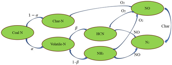
Figure 1.
Formation mechanism of fuel-based NOx.
2.2. Computational Geometry and Mesh
2.2.1. Boiler Structure and Geometry
This study mainly focuses on a 600 MW supercritical pressure, once-through boiler. The boiler adopts one single furnace and a Π-type layout. Its combustion system applies 30 low-NOx axial swirl burners, symmetrically arranged. Figure 2 depicts a schematic representation of the furnace structure along with the arrangement of the burners.
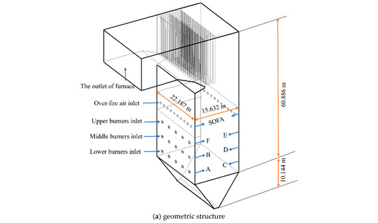
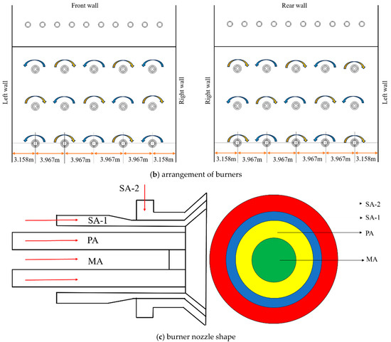
Figure 2.
Geometric model.
2.2.2. Meshing and Validation
This study employs ICEM for meshing the geometric structure and performs grid refinement in the burner area to make the grids more suitable for describing the combustion process, as depicted in Figure 3. As the count of grids increases, the accuracy of the numerical simulation escalates. However, excessive grids provide only a limited improvement in accuracy and increase computational costs. Therefore, three sets of grids with varying quantities are chosen by selecting different levels of grids in the burner area, which are 1.50 million, 1.95 million, and 2.89 million grids, respectively. These grid schemes are employed to conduct the numerical studies at under 100% BMCR.
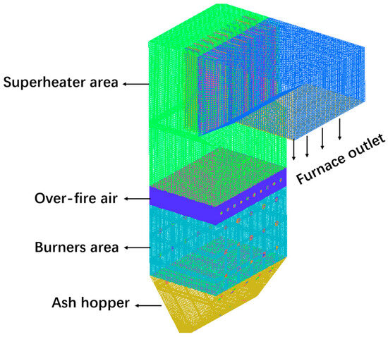
Figure 3.
Computational grid.
During the grid independence validation process, the average temperature taken across the furnace height’s cross-sectional direction is adopted as the key metric. Figure 4 showcases the temperature profile along the furnace’s vertical axis under three distinct grid configurations. As is evident from the graphical depiction, notable temperature fluctuations are discernible within the burner zone, primarily attributed to the ingress of secondary air into the furnace, subsequently diminishing the cross-sectional average temperature at that location. As the number of grids increased from 1.95 million to 2.89 million, there was no significant improvement in the computational accuracy. Adopting the 1.95 million grids scheme could balance the computational accuracy and computational cost.
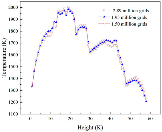
Figure 4.
The temperature distribution in the vertical direction at the center of the furnace.
2.3. Material Properties and Design Parameters of the Boiler
The boiler uses Huainan coal as the experimental coal, and the coal composition is described in Table 2. The components of the ash are listed in Table 3.
Table 2.
Proximate and ultimate analyses of fuels (wt %, as-received basis).
Table 3.
The component analysis of the ash.
Some design parameters of the boiler are listed in Table 4.
Table 4.
Design parameters of the boiler (100% BMCR).
3. Results and Discussion
3.1. Model Validation
The commonly applied method for the boiler thermodynamic calculation was proposed by scholars from the former Soviet Union. This method treats the furnace as a ‘zero-dimensional mode’, assuming that the heat exchange in the furnace equals the enthalpy drop in the flue gas from its theoretical combustion temperature to its exit temperature. Consequently, this allows for the determination of parameters such as the flue gas exit temperature [36]. To authenticate the trustworthiness of the model outputs, this study conducts a comparison between the results of the thermodynamic calculation and the parameters obtained from the numerical study. According to the data presented in Table 5, it is evident that the maximum deviation between the numerically simulated values of the boiler and the thermodynamic calculations is roughly 3%, underscoring the precision and accuracy of the numerical analysis conducted.
Table 5.
Comparison between the thermodynamic calculation and numerical results.
When the boiler operates at a lower load, less air is required for the fuel. More air cannot be allocated to the upper burners (layers E and F). To ensure the symmetry of the airflow distribution in the furnace, air is supplied to the middle burners (layers C and D), which avoids serious thermal load deviations caused by asymmetric flame distribution [23]. As a result, when the boiler operates with OM1, air is supplied to the furnace through the middle-level burners. As presented in Table 6, this paper conducts numerical studies of four operating conditions, namely, running the layer A, B, and C burners (operation mode 1) and the A and C burners (operation mode 2) at 25% BMCR and 35% BMCR, to explore the operating mode of the suitable burners. These two operation modes are named OM1 and OM2, respectively, hereafter for the convenience of narration. When the boiler is operating at a low load, the amount of fuel required is reduced. To ensure the complete combustion of the coal powder, the air entering the furnace is increased and the ratio of primary air to secondary air is maintained within a reasonable range.
Table 6.
Simulation parameters for various cases.
3.2. Furnace Parameter Distribution During Different Working Conditions
3.2.1. Flow Characteristics
Figure 5 visually represents the distribution characteristics of the airflow within the furnace when the boiler runs under different working conditions. The figure indicates that the flow field in the boiler generally presents a symmetrical distribution. The convergence of the airflow originating from the strategically positioned burners occurs centrally, subsequently ascending vertically throughout the entire height of the furnace. The pulverized coal flow from the lower burners partly moves downward after the convergence at the core of the furnace, thus forming a region with a higher air velocity in the ash hopper. To prompt the combustion of pulverized coal, the OFA, which accounts for about 30% of the total air volume, enters from the upper part of the furnace. The OFA could penetrate the flue gas smoothly to the middle of the furnace due to its high wind speed and strong airflow rigidity. Above the arch nose, the flue gas velocity decreases sharply, and backflow occurs [31,37].
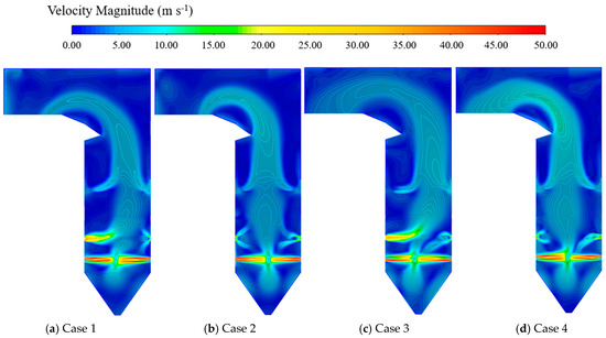
Figure 5.
Velocity distribution of the central longitudinal section of the furnace.
When the boiler adopts OM1, due to the asymmetry of the air volume of the second-layer burners, the directionality of the flow field in the furnace will be skewed towards the front wall, which may cause the flame to be skewed, resulting in slag formation on the front wall heating surface. However, when the boiler adopts OM2, the gas distribution within the furnace is better. Compared to OM1, operating OM2 with fewer burners can enhance the airflow velocity of each individual burner by approximately 30%. The augmentation of the airflow velocity within the furnace fosters an intensified blending of pulverized coal and air, consequently elevating the efficiency of both the thermal and mass transfer processes [9,30,38].
As is evident in Figure 6, the duration of the pulverized coal’s presence within the furnace through the lower-level burners is significantly longer than that of the coal injected from the middle-level burners. Taking the boiler operating at 25% BMCR with OM1 as an example, the pulverized coal that is injected via the lower-level burners maintains its presence within the furnace for a duration of 21 s, while the corresponding duration for the coal from the middle-level burners is 14 s. Due to the longer heating path experienced by the pulverized coal emanating from the lower-level burners, its burnout rate (reaches 99.4%) is also higher. The duration of the pulverized coal’s presence within the furnace decreases due to the rise in the flue gas volume as the operating load of the boiler increases [26]. However, since the temperature level within the furnace also elevates correspondingly, the burnout rate of the pulverized coal is not significantly impacted. Although there is a tendency for more pulverized coal to move towards the ash hopper when OM2 is adopted, the variation in the burnout rate of the pulverized coal is under 1%.
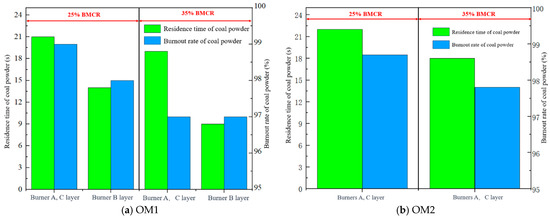
Figure 6.
Coal powder residence time and burnout rate.
3.2.2. Temperature Profile
Figure 7 presents the temperature distribution when the boiler is operating under the 25% BMCR and 35% BMCR conditions. The diagram indicates that the temperature maintains a broadly comparable pattern when the identical operational mode is utilized. The extent of the high-temperature zone expands when the load of the boiler increases. The flame symmetry inside the furnace is poor when the boiler adopts OM1, and the high-temperature area is significantly skewed towards the rear wall, which could lead to an uneven heat load distribution in the furnace and exacerbate the slagging and corrosion of the rear water-cooled wall [9,39]. When OM1 is adopted, the pulverized coal ejected from the lower burners encounters resistance and has greater difficulty moving upwards after meeting in the center of the furnace. In contrast, when the boiler operates in the OM2 mode, the output of each individual burner increases, leading to a tendency for more pulverized coal to enter the ash hopper area when the boiler operates in the OM2 mode. The combined effect of these two factors determines the amount of pulverized coal that enters and burns in the ash hopper. It is evident that the temperature in the ash hopper is higher when the boiler operates under OM1, reaching 1750 K and 1650 K, respectively. This indicates that the obstruction caused by the airflow from the middle burners to the lower pulverized coal is dominant, allowing more pulverized coal to enter and burn in the ash hopper.
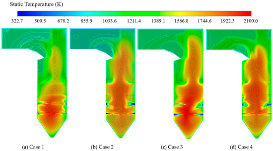
Figure 7.
Temperature distribution in the central longitudinal section of the furnace.
During the low-load operation of the boiler, the primary source of ignition heat for pulverized coal combustion is the swirling secondary air. The secondary air directs flue gas towards the root of the primary air, facilitating the ignition of the pulverized coal. In OM1, the pulverized coal near the rear wall is ejected from two layers of burners, consuming a large amount of O2 and failing to form a good recirculation zone, which hinders the ignition of the pulverized coal and could easily cause slagging and corrosion near the rear wall [24,25]. In contrast, OM2 has the potential to create a low-temperature area in proximity to the water-cooled wall by virtue of the entrainment effect of the swirling secondary air, ensuring the safety of the water-cooled wall.
The introduction of OFA into the furnace ensures the continued combustion of the unburned pulverized coal, resulting in a subsequent increase in the furnace temperature along the height direction [38]. Figure 8 illustrates the influence that various operation modes exert on the temperature throughout the furnace. The average temperature (taking the boiler running with OM2 at 35% BMCR as an example) rapidly increases in the ash hopper (0~10 m), and reaches a peak temperature at around a 9 m height. The temperature increases dramatically as the coal powder is injected by each layer of burners, reaching a peak temperature between adjacent layers of burners, with a temperature of about 1730 K at a height of about 15 m. The OFA, comprising 28% of the total air volume, enters the furnace, causing a reduction in the temperature to 1400 K and compressing the flame in the upper portion. Subsequently, the temperature increases anew as the remaining unburnt carbon undergoes further combustion.
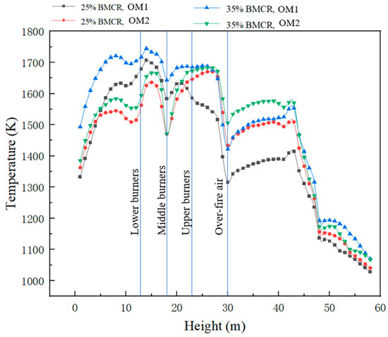
Figure 8.
Temperature along the height of the furnace.
3.2.3. Gas Emission
The distribution of O2 in the furnace makes a notable difference to the combustion and heat transfer of coal powder and the complete combustion of coke [13]. In addition, the O2 atmosphere also affects the emission characteristics of pollutants [37]. The distribution of O2 shown in Figure 9 reveals that when the boiler is operating at a low load, the lower swirl intensity and lower secondary air volume hinder the formation of a good aerodynamic field for the stable combustion and reduction of NOx. Figure 10 shows the mole fraction changes in O2 and CO2 in cross-sections along the height of the furnace. In general, O2 and CO2 show opposite distributions, and when the same operating mode is applied, the component distribution in the furnace are generally similar at different loads, reaching a peak at the burner nozzle and then sharply increasing with the combustion of coal powder. Figure 10a with Figure 10b could reveal that the CO2 content in the ash hopper area is much higher (the CO2 content in the ash hopper area of the boiler operating under OM1 is 4 times that of OM2) in OM1 than that in OM2. This is because the resistance of the coal powder flow from the lower burners is greater in OM1, leading to more coal powder burning in the ash hopper. However, the ash hopper does not receive sufficient oxygen replenishment, which could lead to the incomplete combustion of the pulverized coal [13,40].
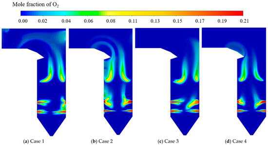
Figure 9.
O2 distribution of the central longitudinal section of the furnace.
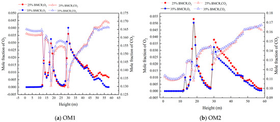
Figure 10.
O2 and CO2 distribution along the height of the furnace.
The distribution of CO and O2 exhibits an inverse pattern [13]. This can be observed by comparing the distribution of O2, as revealed in Figure 9, and the distribution of CO, as shown in Figure 11. The body of previous work has highlighted the fact that the concentration of CO inside the furnace is mainly determined by three factors: the combustion of volatiles producing CO, the combustion of coke producing CO, and CO consumption through oxidation. Among these, the rates of CO generation from volatile combustion and CO oxidation are much higher than the rate of CO generation from coke combustion. Therefore, the distribution of CO inside the furnace depends mainly on the rates of volatile combustion and CO oxidation, both of which are strongly correlated with the distribution of O2 [41].
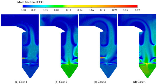
Figure 11.
CO distribution of the central longitudinal section of the furnace.
Boilers operating under the OM1 condition reduce the quantity of pulverized coal injected by each burner and promote the mixing of pulverized coal and air to a certain extent, which results in less CO produced in the main combustion zone. OFA enters the furnace and provides the O2 needed for the combustion of coke and promoting the oxidation and consumption of CO, leading to a sharp decrease in the CO content, as elegantly illustrated in Figure 12 [16,30]. The mole fraction of CO in the ash hopper reaches 0.108 when the boiler employs OM2, whereas this value is merely 0.015 when the boiler adopts OM1. This fact corresponds with the previously mentioned finding, where the application of OM2 results in the emission of more pulverized coal from a single burner nozzle, hindering the full mixing of pulverized coal and air.
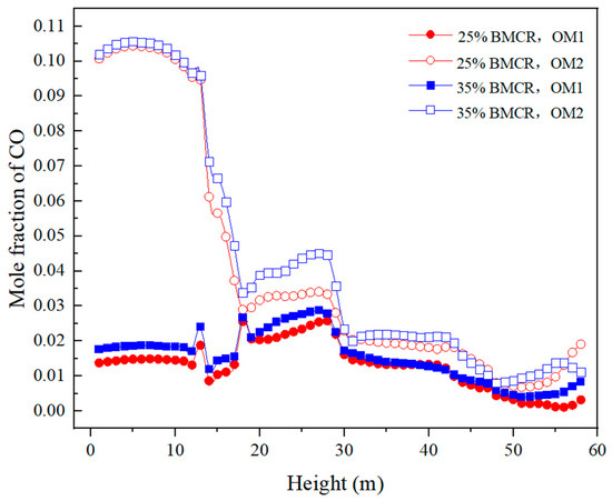
Figure 12.
Distribution of CO along the height of the furnace.
The NOx we usually talk about exists in various forms. The formation of NOx mainly occurs in three ways during the combustion process in boilers, including thermal NOx, prompt NOx, and fuel-based NOx. Under conditions of elevated temperature, thermal NOx arises through the oxidation of nitrogen present in the air. Prompt NOx is generated by the reaction of nitrogen in the air and hydrocarbon ions in the fuel. And fuel-based NOx is formed by the continued oxidation of nitrogen-containing compounds in the fuel after their decomposition. The NOx already present in the flue gas will react with the volatile matter and coke produced by the heating decomposition of coal powder with the generation of NOx. The total amount of NOx generated depends on the competition between the NOx generation reaction and the reduction reaction. In the high-temperature zone within the furnace, thermal NOx is primarily generated. As the flue gas temperature decreases, fuel-based NOx is produced in large quantities. Therefore, when the boiler operates at a low load, NOx is mainly generated in the burner zone and the furnace exit region. When the boiler runs at a high load, the NOx concentration at the furnace outlet decreases due to the higher flue gas temperature [42]. The area with a high CO concentration in the furnace has a good reducing atmosphere, which will inhibit the generation of NOx, which explains the inverse distribution of CO and NOx in Figure 11 and Figure 13.
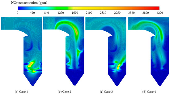
Figure 13.
NOx distribution in the central longitudinal section of the furnace.
The distribution of NOx is shown in Figure 13. As presented in Figure 13, the NOx generated by the boiler when operating at 25% BMCR is significantly higher than that generated when operating at 35% BMCR. This is mainly because when the boiler load is reduced, especially at extremely low loads such as 25% BMCR, the temperature in the furnace drops significantly, resulting in the lower production of thermal NOx. The production of fuel-based NOx becomes the main factor affecting the NOx content [43,44]. In addition, the figure also shows that the NOx generated under the OM2 condition is significantly less than that under the OM1 condition in the burner area. This is because the power of a single burner deviates far from its normal operating range when the boiler operates in OM1, making it difficult for coal powder to form a good NOx reduction zone near the burners and leading to a large amount of fuel-based NOx. However, when the boiler adopts OM2, significant amounts of NOx are generated in the upper part of the furnace and at the outlet [35,45]. Taking 25% BMCR as an example, when OM2 is employed, the NOx concentration at the furnace outlet reaches 1083 ppm, whereas with OM1, this value is 743 ppm. Such severe pollutant emissions are not permissible and pose a new challenge to the desulfurization and denitrification systems of boilers. The primary reason for the observed phenomenon lies in the fact that there is no additional pulverized coal fed into the middle burners when the boiler employs OM2, resulting in a sharp decrease in temperature along the height of the furnace. In particular, the insufficient turbulence in the recirculation zone leads to a lack of vigorous airflow disturbance, which subsequently contributes to the significant generation of fuel-based NOx in the upper part of the furnace [13,16].
4. Conclusions
Numerical stimulations were employed on a 600 MW wall-fired boiler with the CFD method to investigate the combustion characteristics within the furnace when the boiler operates at low loads. This study also investigated the optimal operation mode for the boiler by comparing the performance characteristics within the furnace when the boiler adopts two different combustion schemes. The subsequent inferences can be deduced.
(1) When the boiler operates at 25% and 35% BMCR, OM2 could better organize the flow field compared to OM1. The gas flow velocity can be increased by approximately 32% compared to that of OM1 when the boiler adopts OM2. As a result, the blending of coal powder and air inside the furnace is promoted and the combustion process of the coal powder is accelerated. OM2 ensures a better airflow distribution and maintains the focal point of elevated temperatures precisely at the center of the furnace, thereby effectively mitigating deviations in the thermal load experienced by the water-cooled wall. Furthermore, the difference in the burnout rate of pulverized coal between the two operation modes is less than 1%.
(2) When the boiler applies OM1, the temperature in the ash hopper is significantly higher than that in OM2, with values of 1750 K and 1650 K, respectively. This fact indicates that the obstruction caused by the airflow from the middle burners to the lower pulverized coal is dominant, allowing more pulverized coal to enter and burn in the ash hopper. Approximately 30% of the total air volume, referred to as OFA, enters the furnace to assist in the continued combustion of unburned carbon and serves to compress the flame.
(3) The various operation modes exert a notable influence on the composition field. More pulverized coal enters the ash hopper for combustion when OM1 is employed, leading to a mole concentration of CO2 in this region reaching 0.04, which is about 6.5 times that under OM2. Conversely, the pulverized coal only enters the furnace through the lower burners when OM2 is applied, hindering the mixing of pulverized coal and air. This results in the substantial generation of CO in the ash hopper (when OM1 applied, the mole fraction concentration of CO in the ash hopper reaches 0.105, which is approximately 5 times the value observed under OM2).
(4) As the boiler load diminishes, there is a marked surge in NOx production, primarily attributed to the reduced temperature within the furnace, fostering the creation of substantial quantities of fuel-based NOx. Although a significant amount of NOx is produced when the boiler operates at 25% and 35% BMCR individually, the primary production areas exhibit opposite characteristics. Taking 25% BMCR as an example, the NOx concentration at the furnace outlet reaches 1083 ppm when OM2 is utilized, while this value is 643 ppm when OM1 is adopted. The high NOx emissions are attributable to the faster attenuation of temperature along the furnace, which leads to the formation of a large amount of fuel-based NOx.
Author Contributions
Conceptualization, P.C. and J.L.; methodology, P.C.; software, X.Z.; validation, P.C., J.L. and L.D.; formal analysis, L.D.; investigation, P.C.; resources, J.L.; data curation, D.J.; writing—original draft preparation, P.C.; writing—review and editing, P.C.; visualization, D.J.; supervision, X.Z.; project administration, L.D.; funding acquisition, L.D. All authors have read and agreed to the published version of the manuscript.
Funding
This research was funded by the Guangdong Administration for Market Regulation Science and Technology Project grant number 2014CT12.
Data Availability Statement
The data presented in this study are available on request from the corresponding author. The data are not publicly available due to privacy.
Conflicts of Interest
Authors P.C., J.L. and X.Z. were employed by the company Shanghai Power Equipment Research Institute. The remaining authors declare that the research was conducted in the absence of any commercial or financial relationships that could be construed as a potential conflict of interest.
References
- Tian, X.; Fan, C. Analysis of Deep Peak Regulation and Its Benefit of Thermal Units in Power System With Large Scale Wind Power Integrated. Power Syst. Technol. 2017, 41, 2255–2263. [Google Scholar]
- Wang, C.; Liu, M.; Zhao, Y.; Qiao, Y.; Chong, D.; Yan, J. Dynamic modeling and operation optimization for the cold end system of thermal power plants during transient processes. Energy 2018, 145, 734–746. [Google Scholar] [CrossRef]
- Gu, Y.; Xu, J.; Chen, D.; Wang, Z.; Li, Q. Overall review of peak shaving for coal-fired power units in China. Renew. Sustain. Energy Rev. 2016, 54, 723–731. [Google Scholar] [CrossRef]
- Guo, J.-X.; Huang, C. Feasible roadmap for CCS retrofit of coal-based power plants to reduce Chinese carbon emissions by 2050. Appl. Energy 2020, 259, 114112. [Google Scholar] [CrossRef]
- Wang, H.; Zou, C.; Hu, H.; Gu, G.; Dong, L.; Huang, Y.; Deng, S.; Li, S. Migration and emission characteristics of trace elements in coal-fired power plant under deep peak load regulation. Sci. Total Environ. 2023, 868, 161626. [Google Scholar] [CrossRef]
- Du, H.; Li, Z.; Liu, Z.; Zhang, M.; Huang, C.; Jiang, G.; Chen, Z.; Song, J.; Fang, F.; Su, J.; et al. Industrial measurement of combustion and NOx formation characteristics on a low-grade coal-fired 600MWe FW down-fired boiler retrofitted with novel low-load stable combustion technology. Fuel 2022, 321, 123926. [Google Scholar] [CrossRef]
- Hong, F.; Chen, J.; Wang, R.; Long, D.; Yu, H.; Gao, M. Realization and performance evaluation for long-term low-load operation of a CFB boiler unit. Energy 2021, 214, 118877. [Google Scholar] [CrossRef]
- Liu, Y.; Fan, W.; Li, Y. Numerical investigation of air-staged combustion emphasizing char gasification and gas temperature deviation in a large-scale, tangentially fired pulverized-coal boiler. Appl. Energy 2016, 177, 323–334. [Google Scholar] [CrossRef]
- Jin, W.; Si, F.; Kheirkhah, S.; Yu, C.; Li, H.; Wang, Y.O. Numerical study on the effects of primary air ratio on ultra-low-load combustion characteristics of a 1050 MW coal-fired boiler considering high-temperature corrosion. Appl. Therm. Eng. 2023, 221, 119811. [Google Scholar] [CrossRef]
- Wang, Q.; Chen, Z.; Li, L.; Zeng, L.; Li, Z. Achievement in ultra-low-load combustion stability for an anthracite-and down-fired boiler after applying novel swirl burners: From laboratory experiments to industrial applications. Energy 2020, 192, 116623. [Google Scholar] [CrossRef]
- Ma, D.; Zhang, S.; He, X.; Ding, X.; Li, W.; Liu, P. Combustion stability and NOx emission characteristics of three combustion modes of pulverized coal boilers under low or ultra-low loads. Appl. Energy 2024, 353, 121998. [Google Scholar] [CrossRef]
- Chen, G.; Li, Z.; Zhang, H.; Huang, L.; Liu, Z.; Fan, W. Influences of ultra-low load operation strategies on performance of a 300 MW subcritical bituminous coal boiler. Appl. Therm. Eng. 2024, 256, 124037. [Google Scholar] [CrossRef]
- Wang, H.; Jin, H.; Yang, Z.; Deng, S.; Wu, X.; An, J.; Sheng, R.; Ti, S. CFD modeling of flow, combustion and NOx emission in a wall-fired boiler at different low-load operating conditions. Appl. Therm. Eng. 2024, 236, 121824. [Google Scholar] [CrossRef]
- Fang, Q.; Wang, H.; Zhou, H.; Lei, L.; Duan, X. Improving the Performance of a 300 MW Down-Fired Pulverized-Coal Utility Boiler by Inclining Downward the F-Layer Secondary Air. Energy Fuels 2010, 24, 4857–4865. [Google Scholar] [CrossRef]
- Xie, X.-Q.; Yang, J.-G.; Zhu, C.-Y.; Liu, C.-H.; Zhao, H.; Wang, Z.-H. Numerical analysis of reasons for the CO distribution in an opposite-wall-firing furnace. J. Zhejiang Univ. Sci. A 2020, 21, 193–208. [Google Scholar] [CrossRef]
- Luo, R.; Fu, J.; Li, N.; Zhang, Y.; Zhou, Q. Combined control of secondary air flaring angle of burner and air distribution for opposed-firing coal combustion. Appl. Therm. Eng. 2015, 79, 44–53. [Google Scholar] [CrossRef]
- Fang, Q.; Wang, H.; Wei, Y.; Lei, L.; Duan, X.; Zhou, H. Numerical simulations of the slagging characteristics in a down-fired, pulverized-coal boiler furnace. Fuel Process. Technol. 2010, 91, 88–96. [Google Scholar] [CrossRef]
- Li, X.; Zeng, L.; Zhang, N.; Chen, Z.; Li, Z.; Qin, Y. Effects of the air-staging degree on performances of a supercritical down-fired boiler at low loads: Air/particle flow, combustion, water wall temperature, energy conversion and NO emissions. Fuel 2022, 308, 121896. [Google Scholar] [CrossRef]
- Wang, H.; Liu, J. Influence of operation of industrial boilers under low load on overheaters. Met. Power. 2001, 6, 47–48. [Google Scholar]
- Yuan, L. Numerical Simulation of Variable Load Combustion of Supercritical Pulverized Coal Boiler and Optimization of Air. Master’s Thesis, Southeast University, Nanjing, China, 2019. (In Chinese). [Google Scholar]
- Wang, D.; Yang, Z.; Ran, S.; Deng, J.; Li, Z. Numerical study and application of steady combustion under low load for inferior coal. Clean Coal Technol. 2023, 29, 181–187. (In Chinese) [Google Scholar]
- Tu, B.; Li, D.; Liao, W.; Lv, W.; Jin, F.; Yan, C.; Yin, Q.; Chen, Z.; Que, Z.; Kan, W.; et al. Simulation research on low load operation and environment performance of supercritical opposite combustion boiler. Electr. Power Technol. Environ. Prot. 2024, 40, 407–415. (In Chinese) [Google Scholar]
- Li, S.; Chen, Z.; He, E.; Jiang, B.; Li, Z.; Wang, Q. Combustion characteristics and NO formation of a retrofitted low-volatile coal-fired 330 MW utility boiler under various loads with deep-air-staging. Appl. Therm. Eng. 2017, 110, 223–233. [Google Scholar] [CrossRef]
- Liu, S. Numerical Simulation of Combustion Optimization for a 600MW Swirl-Opposed Firing Boiler. Master’s Thesis, Huazhong University of Science and Technology, Wuhan, China, 2019. (In Chinese). [Google Scholar]
- Zhong, L.; Deng, J.; Sun, W.; Yuan, L.; Fang, Q.; Tan, P.; Zhang, C.; Chen, G. Effects of Burner Operation Mode on Performance of the Boiler Under Low Load Conditions. J. Chin. Soc. Power Eng. 2015, 35, 693–698. (In Chinese) [Google Scholar]
- Fang, Q.; Wang, H.; Chen, G.; Zhou, H. Numerical stimulation on effects of over fire air on the combustion characteristics in an ultra-supercritical boiler. J. Huazhong Univ. Sci. Tech. 2010, 38, 92–95. (In Chinese) [Google Scholar]
- Liu, W.; Yang, M.; Zhang, Y.; Li, Y.; Ying, X.; Huang, W. Improving the asymmetric phenomenon effects on the combustion characteristics in an opposed-fired pulverized coal boiler. Numer. Heat Transf. Part A Appl. 2023, 83, 790–813. [Google Scholar] [CrossRef]
- Ma, X.; Yang, M.; Zhang, Y. Analysis of Combustion Mechanism and Combustion Optimization of a 300 mw Pulverized Coal Boiler. Front. Heat Mass Transf. 2016, 7, 36. [Google Scholar] [CrossRef]
- Chen, H.; Fang, Y. Experimental study on economic improvement of updraft boiler under low load. Electr. Power Technol. Environ. Prot. 2024, 40, 160–167. (In Chinese) [Google Scholar]
- Zhang, X.; Chen, Z.; Zhang, M.; Zeng, L.; Li, Z. Combustion stability, burnout and NO emissions of the 300-MW down-fired boiler with bituminous coal: Load variation and low-load comparison with anthracite. Fuel 2021, 295, 120641. [Google Scholar] [CrossRef]
- Yuan, L.; Zhong, W.; Chen, X.; Li, J.; Liu, G.; Tian, W. Three-dimensional numerical simulation of variable load combustion of supercritical coal-fired boiler for deep peak load regulation. J. Southeast Univ. 2019, 49, 535–541. (In Chinese) [Google Scholar]
- Lv, H.; Tong, J.; Qi, X.; Liu, J. Numerical Simulation of Low-load Operation Optimization for Opposite Firing Boilers. J. Eng. Therm. Energy Power 2020, 35, 89–94. (In Chinese) [Google Scholar]
- Ren, Y.; Mahinpey, N.; Freitag, N. Kinetic model for the combustion of coke derived at different coking temperatures. Energy Fuels 2007, 21, 82–87. [Google Scholar] [CrossRef]
- Cheng, P. Two-dimensional radiating gas flow by a moment method. AIAA J. 1964, 2, 1662–1664. [Google Scholar] [CrossRef]
- Zhao, K.T.; Zhou, Q.; Xu, T. The Law of HCN and NH3 Escape during the Pyrolysis of Model Compounds of Coal. J. Eng. Therm. Energy Power 2004, 19, 246–248+322–323. (In Chinese) [Google Scholar] [CrossRef]
- Zhang, Z.; Li, X.; Luo, C.; Zhang, L.; Xu, Y.; Wu, Y.; Liu, J.; Duan, Y.; Zheng, C. Investigation on the thermodynamic calculation of a 35 MWth oxy-fuel combustion coal-fired boiler. Int. J. Greenh. Gas Control 2018, 71, 36–45. [Google Scholar] [CrossRef]
- Liu, X.; Zhong, W.; Li, J.; Liu, L.; Liu, G.; Tian, W. Three-dimensional numerical stimulation on optimization air distribution for combustion of ultra-supercritical boiler. J. Southeast Univ. 2018, 48, 794–800. (In Chinese) [Google Scholar]
- Cao, Y. Numerical Simulation of Low NOx Operation Optimization for a 660 MW Opposed Swirling Fired Utility Boiler. Master’s Thesis, Huazhong University of Science and Technology, Wuhan, China, 2014. (In Chinese). [Google Scholar]
- Mao, R.; Li, Y.; Ren, L.; Zhang, P.; Ma, L.; Chen, X.; Zhang, G.; Fang, Q.; Zhang, C. Numerical stimulation on burner burnout characteristics and optimization in a 600 MW swirling oppsed boiler. Clean Coal Technol. 2022, 28, 117–124. (In Chinese) [Google Scholar]
- Nowak, K.; Rabczak, S. Co-combustion of biomass with coal in grate water boilers at low load boiler operation. Energies 2021, 14, 2520. [Google Scholar] [CrossRef]
- Tan, P.; Tian, D.; Fang, Q.; Ma, L.; Zhang, C.; Chen, G.; Zhong, L.; Zhang, H. Effects of burner tilt angle on the combustion and NOX emission characteristics of a 700 MWe deep-air-staged tangentially pulverized-coal-fired boiler. Fuel 2017, 196, 314–324. [Google Scholar] [CrossRef]
- Li, J.; Yuan, S.; Liang, Q. Formation of HCN and NH3 during the Rapid Pyrolysis of Coal and Model Compounds. J. Chem. Eng. Chin. Univ. 2011, 25, 55–60. [Google Scholar]
- Xu, M.; Azevedo, J.; Carvalho, M. Modelling of the combustion process and NOx emission in a utility boiler. Fuel 2000, 79, 1611–1619. [Google Scholar] [CrossRef]
- Habib, M.; Elshafei, M.; Dajani, M. Influence of combustion parameters on NOx production in an industrial boiler. Comput. Fluids 2008, 37, 12–23. [Google Scholar] [CrossRef]
- Kuang, M.; Li, Z. Review of gas/particle flow, coal combustion, and NOx emission characteristics within down-fired boilers. Energy 2014, 69, 144–178. [Google Scholar] [CrossRef]
Disclaimer/Publisher’s Note: The statements, opinions and data contained in all publications are solely those of the individual author(s) and contributor(s) and not of MDPI and/or the editor(s). MDPI and/or the editor(s) disclaim responsibility for any injury to people or property resulting from any ideas, methods, instructions or products referred to in the content. |
© 2024 by the authors. Licensee MDPI, Basel, Switzerland. This article is an open access article distributed under the terms and conditions of the Creative Commons Attribution (CC BY) license (https://creativecommons.org/licenses/by/4.0/).