1. Introduction
Buckling is a critical failure mode in thin-walled structures, where instability occurs under compressive loading, leading to sudden deformation. This phenomenon is influenced by factors such as geometry, material properties, and loading conditions, making the prediction of buckling behavior essential for ensuring the structural integrity of thin-walled components [
1,
2].
Silos are used to store powdery or granular bulk solids [
3,
4,
5,
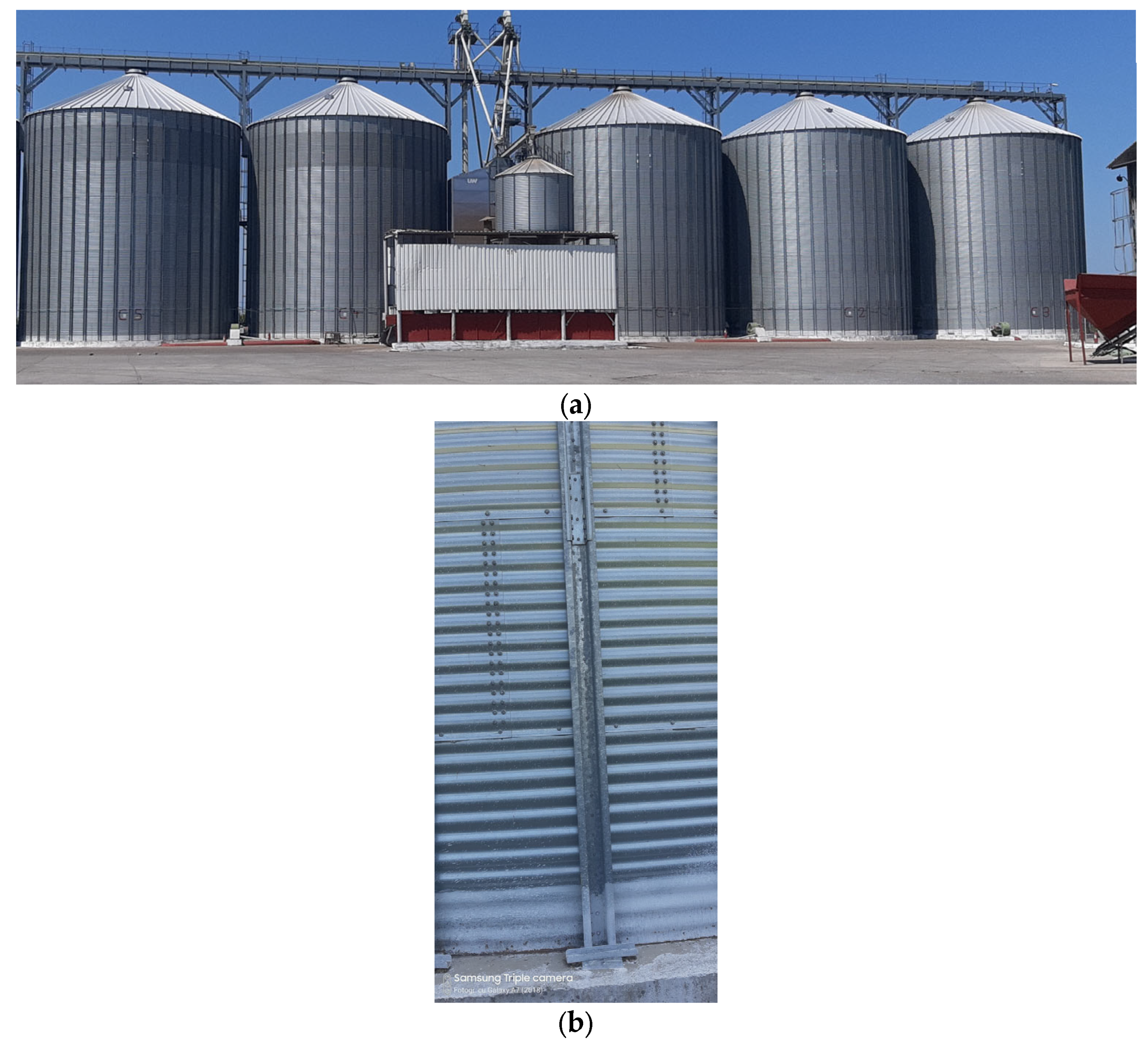
6]. These structures are fabricated in a multitude of shapes and sizes, but the most often used are the cylindrical vertical silos, which are made of steel and can have flat or corrugated walls. Because they have very thin wall thicknesses, they are very sensitive to the buckling phenomenon caused by the friction force due to the interaction between the material stored, the silo walls, and the external loads (wind or earthquakes) [
7]. Silos with horizontally corrugated walls are usually strengthened with vertical stringers uniformly distributed around the silo perimeter (see
Figure 1), and so the walls carry circumferential tensile forces caused by the horizontal wall pressure of the stored materials and the vertical columns carry vertical compressive forces exerted by friction between the wall and the bulk solids [
8,
9,
10]. The main advantages of using these types of silos compared to those with flat walls are the fast assembly rates and low steel costs [
9].
The buckling of silos with flat walls under axial compression has been extensively studied in several research works [
11,
12,
13,
14,
15,
16,
17,
18,
19], emphasizing the significant risk posed by this phenomenon, particularly due to the sensitivity of such structures to geometric imperfections.
In contrast, there are relatively few studies that specifically focus on the buckling strength of silos with corrugated walls under axial compression, despite the unique structural advantages offered by the corrugation profile.
One study [
9] focuses on examining the stability of steel cylindrical silos constructed with corrugated walls and vertical open-sectional stringers. Corrugated walls were modeled as equivalent orthotropic shells, while vertical open-sectional stringers were represented as beam elements. The finite element results were compared with those obtained through the Eurocode methodology. Furthermore, thorough finite element computations were performed for axially compressed cylindrical shells, incorporating an orthotropic shell and stringers. The study suggests enhancements to existing standard formulae based on the findings. A similar investigation is performed in [
20], where instead of conducting comprehensive three-dimensional computations for the entire silo structure, a simplified model of a silo wall segment with a limited number of columns was proposed to calculate the global buckling strength of silos. This approach was applied to analyze three real silos with varying geometries, including two slender silos and one intermediate slender silo. Silos were primarily modeled using an equivalent orthotropic shell for the walls and one-dimensional beam elements for the thin-walled columns, although shell elements were also utilized for both walls and columns in some cases. Another study [
21] presents an experimental and numerical analysis of buckling resistance in a single corrugated silo column, conducting the experiments on a real silo, both empty and filled with wheat, and showing a significant positive impact of the bulk solids on buckling resistance. A comparison with the Eurocode 3 formulae revealed these were overly conservative for both conditions. Finite element simulations, incorporating initial geometric imperfections from geodetic measurements or linear bifurcation analyses, showed good agreement with experimental results, particularly for the empty silo.
The outcomes presented in references [
4,
9,
22,
23,
24,
25,
26,
27] clearly demonstrate that the approach outlined in the Eurocode [
28] consistently underestimates the buckling strength of silos, particularly in cases where columns are sparsely distributed.
The objective of the authors of a previous study [
7] was to assess the practicality of the methodology outlined in Eurocode 3 for determining the critical buckling pressure of metallic cylindrical silo shells featuring corrugated walls and vertical open-sectional stringers by comparing the Eurocode-based calculations with numerical simulations and emphasizing the impact of ribs on the silo’s buckling strength. The aim of the present paper is to analyze the influence of the geometrical characteristics of silos, such as radius, wall thickness, and corrugation profile, on their buckling behavior when subjected to axial compression, using an analytical, numerical, and statistical analysis.
2. Analytical Calculation
For the circular silos with flat walls, the axial critical buckling load in elastic domain is determined with the following formula:
where
t—wall thickness;
R—silo radius;
E—Young modulus for the silo material.
If there are stiffeners, the wall design under axial compression is made with the same criteria as the unstiffened wall. If the distance between stiffeners is smaller than
, it is also permissible to use the procedures of global analysis from EN 1993-1-6 [
29].
In the case of silos made of corrugated sheets with circumferential stiffeners, there are two situations: silos with unstiffened walls and silos with stiffened walls, respectively.
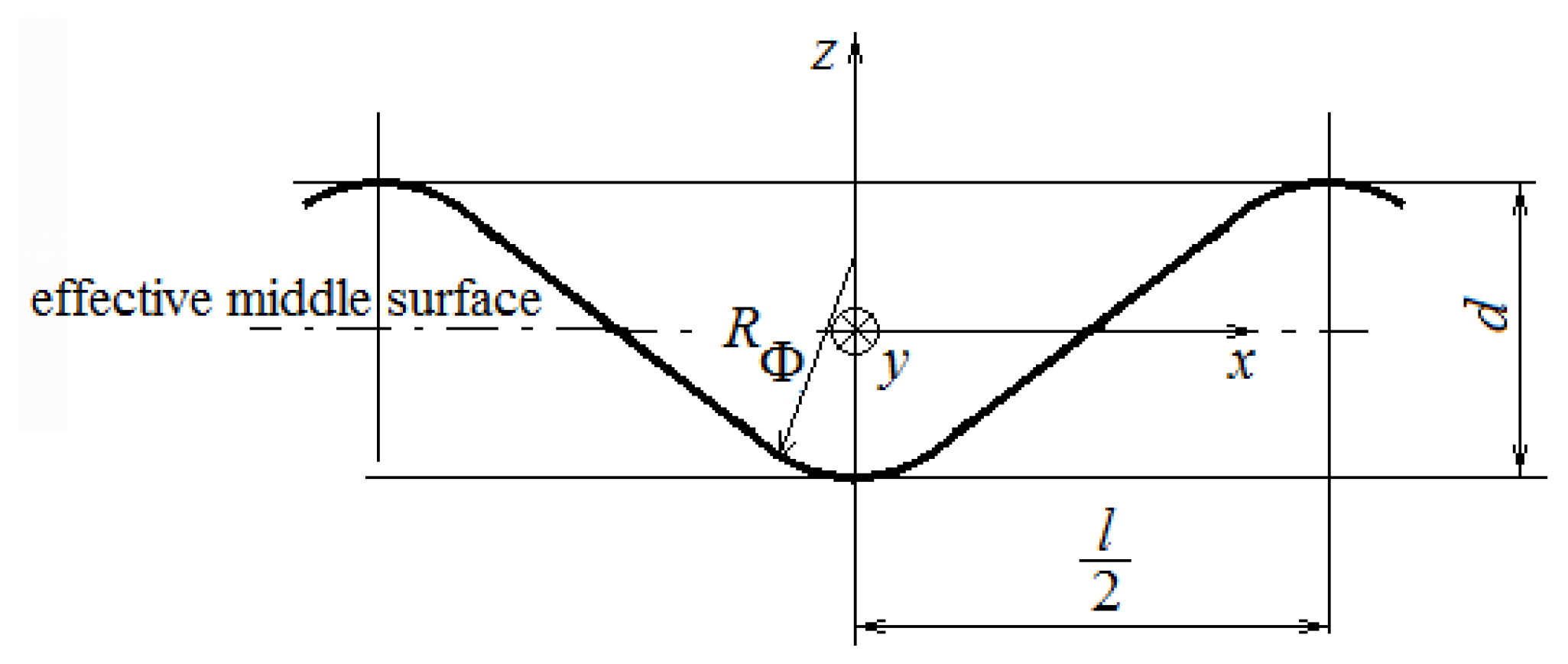
The axial critical buckling load of the corrugated unstiffened wall is as follows:
where
t is the wall thickness [mm],
R is the cylinder radius [mm],
fy is the yield strength of steel [MPa],
d is the corrugation amplitude [mm], and
Rφ is the corrugation local curvature [mm] (see
Figure 2).
In the case of silos with stiffened walls, they should be analyzed in two situations as a function of the distance between stiffeners, calculated as follows:
where
kdx is a coefficient with the recommended value of
kdx = 7.4, according to standard EN 1993-4-1 [
27];
Dy is the flexural rigidity per unit width of the thinnest sheeting parallel to the corrugations calculated with (4) [Nmm]; and
Cy is the stretching stiffness per unit width of the thinnest sheeting parallel to the corrugations calculated with (5) [N/mm].
L is the wavelength of the corrugation (
Figure 2).
If the distance between the stiffeners is ds < ds,max, the stiffened wall of the silo is treated as an anisotropic shell and the axial critical buckling load is determined with the methodology presented in EN 1993-4-1.
If the distance between the stiffeners is
ds >
ds,max, it can be assumed that the side surface of the profiled sheeting does not transfer the longitudinal force, but constitutes a support for the rib. The buckling capacity of the vertical stringer is expressed by the following equations:
where
EIy—the bending stiffness of the stringer in the plane perpendicular to the wall [Nmm
2];
K—the bending stiffness of the sheathing between the stringers, according to Equation (8) [N/mm
2];
Aeff—the effective cross section of the rib; and γ
M1—a partial coefficient relative to the load capacity (γ
M1 = 1.1).
where
ks—a coefficient whose value recommended by EN 1993-4-1:2007 [
29] amounts to 6.0; and
Dy—the bending (plate) stiffness of the sheathing under circumferential bending, according to Equation (4).
The critical value is determined as the minimum of the values calculated with (6) and (7) as follows:
Figure 3 presents the variation in the number of stringers
N with the dimension
d presented in
Figure 2, established with the relation (3) for the following:
E = 2.1·10
5 MPa;
kdx = 7.4;
l = 76 mm;
t = 1 mm and different radii of the silo.
3. Design of Experiments
The statistical analysis was performed with Minitab 2019 software, using a full factorial design of the experiments. The input factors were external radius, silo wall thickness, and corrugation height (see
Figure 2), while the response variables were the critical buckling load calculated with Formula (7), and also panel weight. For the analysis, it was considered to be a cylindrical panel with a constant height of
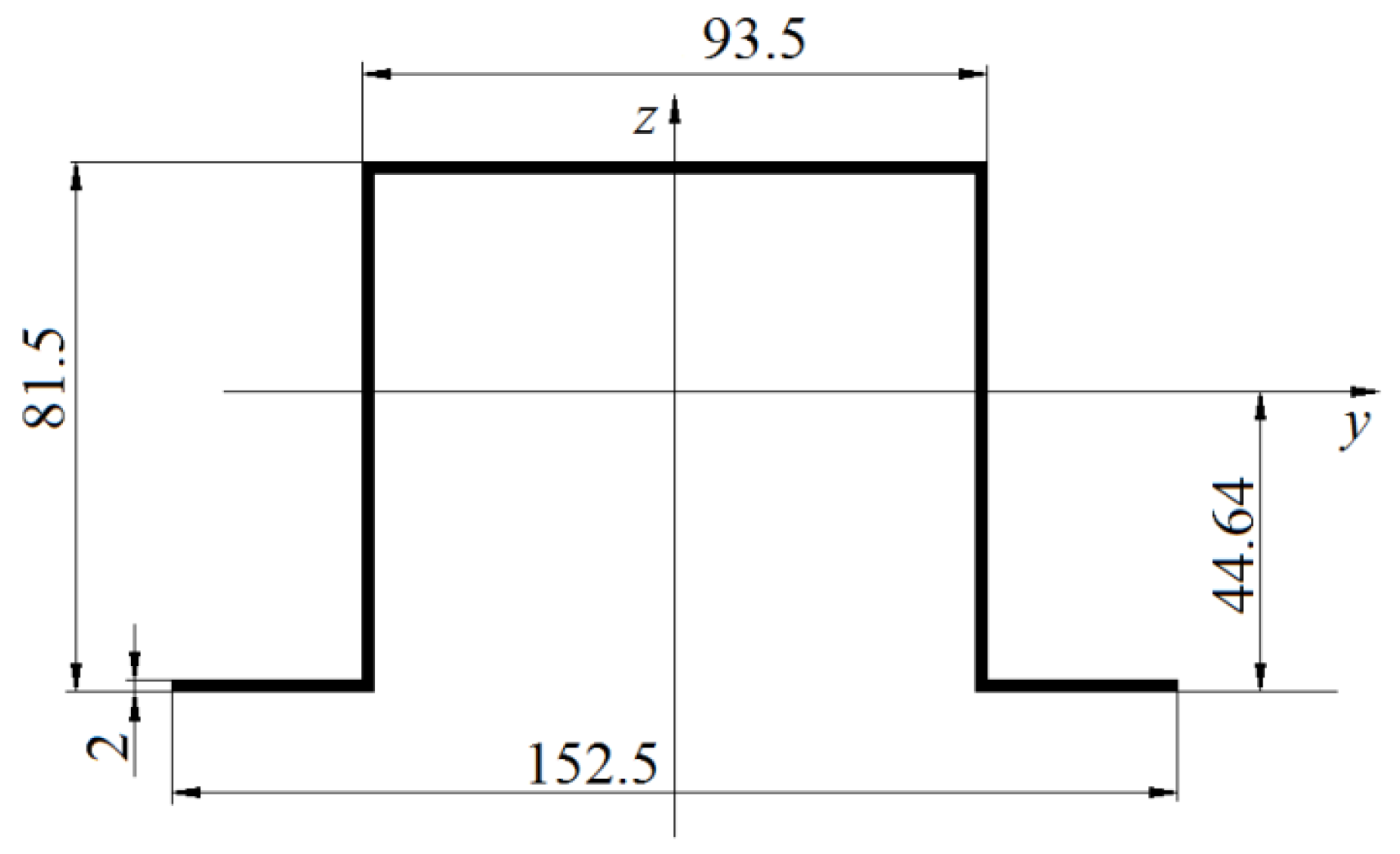
H = 1500 mm and 10 vertical stringers with the dimensions presented in
Figure 4. For each input factor, three levels were considered, resulting in 3
3 = 27 scenarios.
4. Numerical Analysis
A numerical analysis using the finite element method was carried out for a model with the following geometrical characteristics: external radius R = 2500 mm; wall thickness t = 1, 1.5, 2, 2.5, and 3 mm; corrugation profile d = 18 mm; and l = 76 mm. The commercial software ANSYS Mechanical APDL 2021 R1 was used to perform the linear buckling analysis (Eigen Buckling analysis type) to assess the buckling behavior of a steel cylindrical silo with corrugated walls under axial compression loading. This analysis was selected as it provides an estimate of the critical buckling load and identifies the buckling modes.
Figure 5 presents the model used, based on silo symmetry. As in other scientifical works [
10,
20,
21], in order to reduce computational time, a simplified numerical model (corresponding to a vertical stiffener) consisting of 2880 finite elements was modeled, and therefore symmetry boundary conditions were used for the vertical edges of the model, while simply supported boundary conditions were considered for the cylinder’s upper and lower parts. The finite element used for both the cylindrical wall and for the stiffener was SHELL93. The element “SHELL93” refers to a parabolic, 8-node shell element used in finite element analysis. This element can represent curved surfaces and includes both membrane and bending behaviors, making it suitable for modeling complex geometries and non-linear stress distributions.
5. Results and Discussion
5.1. Analytical and Numerical Results
To highlight the influence of dimension
d (see
Figure 1) on the axial critical buckling load, a stiffener with the geometry presented in
Figure 3 was considered, for which
A = 623 mm
2, and
Iy = 640,388 mm
4.
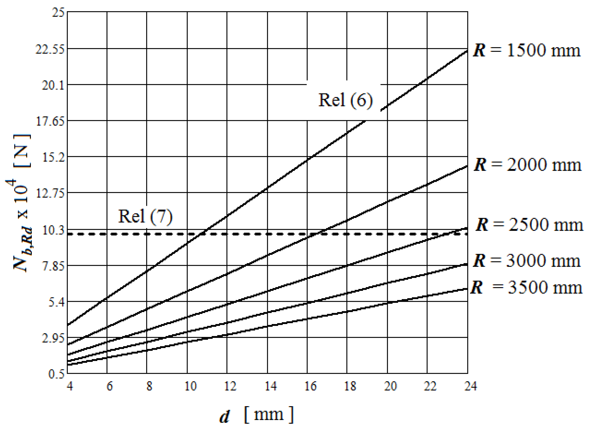
Figure 6 presents the variation in the axial critical buckling load, calculated with relations (6) and (7) as a function of
d, for
E = 2.1·10
5 MPa;
kdx = 7.4;
l = 76 mm;
t = 1 mm;
ks = 6; ρ = 0.748,
fy = 235 MPa;
N = 10-vertical stiffeners and different radii of the silo.
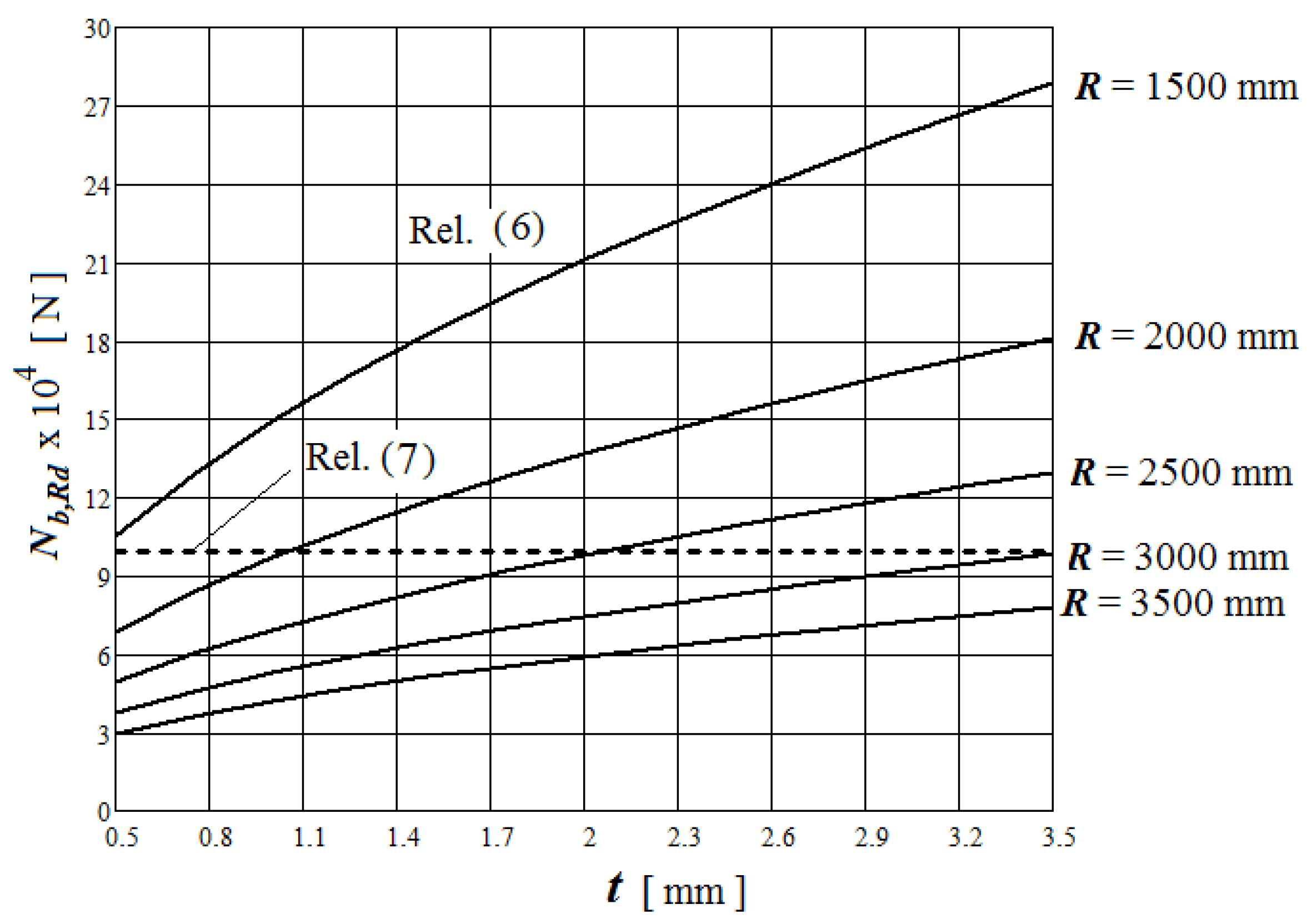
Figure 7 presents the variation in the axial critical buckling load as a function of cylindrical wall thickness
t for
E = 2.1·10
5 MPa;
kdx = 7.4;
l = 76 mm;
d = 16 mm;
ks = 6; ρ = 0.748,
fy = 235 MPa, and
N = 10-vertical stiffeners, and different radii of the silo.
The following can be concluded:
For the situation where
ds > dsmax,
Table 1 presents the values of
(calculated with relation (9)) for different silo wall values
t, for a corrugated cylinder, considering the following values:
R = 2500 mm,
d = 18 mm;
l = 76 mm;
fy = 235 MPa;
A = 623 mm
2 (see
Figure 4);
Iy = 640,388 mm
4,
kdx = 7.4;
ks = 6; γ
M1 = 1.1; ρ = 0.748.
Based on the
value and the number of stiffeners
N, the axial critical buckling load can be determined as follows:
From
Table 1 it can be observed that starting with
t = 2.5 mm,
is imposed by relation (7), meaning that the critical load is imposed by the stiffener buckling.
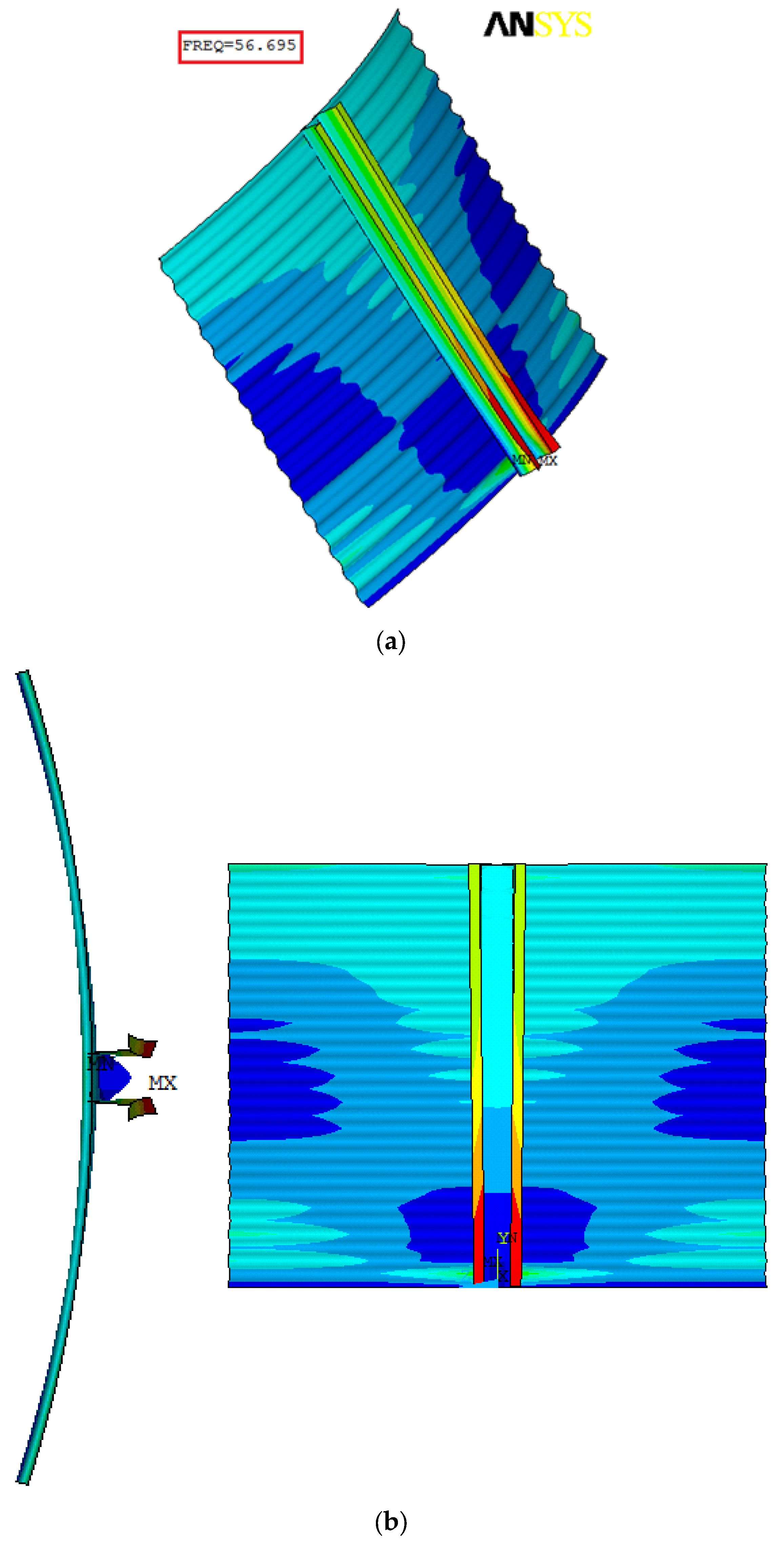
In
Figure 8 it can be observed that the first buckling mode shape and the critical axial buckling load
. For different values of cylindrical wall thickness
t, the values determined with FEM for
are presented in
Table 1.
5.2. Statistical Analysis
The results regarding the critical buckling load and the panel weight for all the scenarios considered are presented in
Table 2.
In order to highlight the influence of input variables on the responses (buckling resistance and panel weight), Pareto charts from
Figure 9 were drawn and it can be seen that the critical buckling load is mainly influenced by corrugation height and less by wall thickness, while the panel weight is influenced almost equally by radius and wall thickness and corrugation height has almost no influence.
On the other hand, the main effect plots from
Figure 10 allow us to establish the best combination of input parameters for maximum buckling resistance (a radius of 1500 mm, a wall thickness of 2 mm, and a corrugation height of 24 mm) and for minimum panel weight (a radius of 1500 mm, a wall thickness of 1 mm, and a corrugation height of 8 mm).
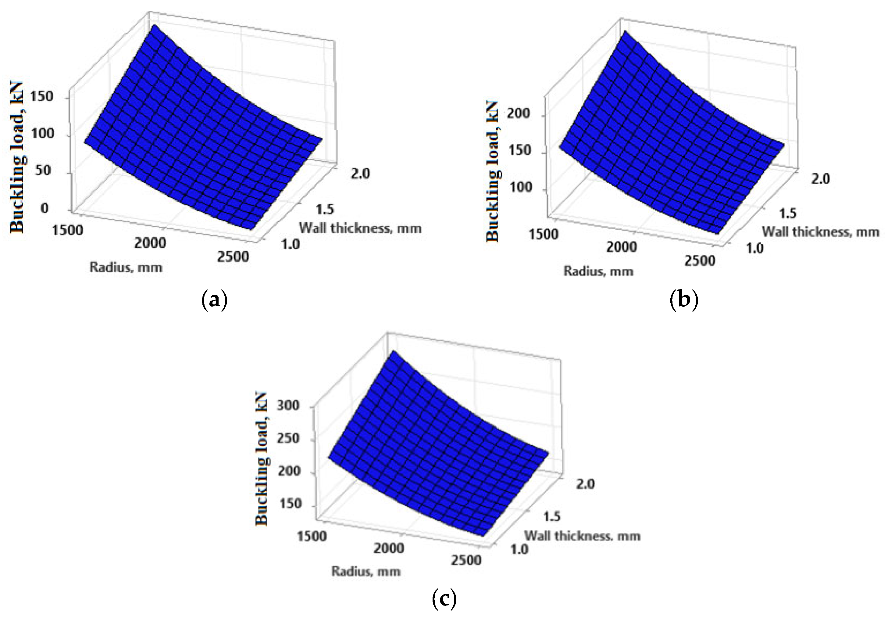
The surface plots from
Figure 11 represent the buckling load as a function of radius and wall thickness. In
Figure 11a, which shows a corrugation height of
d = 8 mm, the maximum buckling load is around 150 kN for this set of parameters. When the corrugation height is
d = 16 mm (
Figure 11b), the maximum buckling load is shown to be around 200 kN, while the maximum buckling load in the plot from
Figure 11c (
d = 24 mm) exceeds 300 kN, which indicates a further optimization of silo structure. Therefore, the plots suggest that increasing the wall thickness generally increases the buckling load capacity, and that changes in the radius of the silo also impact the buckling load.
The multi-objective desirability analysis allows for the identification of the optimal combination of input parameters that result in the maximum buckling resistance and the minimum weight of structure (optimization goals presented in
Table 3) for the 27 analyzed scenarios presented above.
The optimization was performed using the Desirability Function in Minitab 19 software. This analysis assigns values on a scale from zero to one, with a score of one indicating the highest level of suitability.
For the case where the importance is the same for each response, the composite desirability
D is calculated with the following formula [
30]:
where
n is the number of responses and
di represents the desirability for each individual response, calculated as follows:
- -
When the goal is to maximize the response desirability,
- -
When the goal is to minimize the response desirability,
where yi, Ti, Li, and Ui represent the predicted value, target value, lowest value, and highest value, respectively, of the analyzed response.
The optimization plot from
Figure 12, obtained with Minitab 19 software, reveals a composite desirability,
D = 0.9039, that indicates how well the optimization goals were achieved. A desirability score close to 1 (like 0.9039 here) indicates that the solution is near-optimal for all the objectives combined. The plot indicates an optimization scenario where various combinations of radius, wall thickness, and corrugation type are tested to meet two specific goals: minimizing panel weight and maximizing buckling resistance. It can be seen in
Figure 12 that for achieving these goals, the following should be used: 1500 mm radius, 1 mm wall thickness, and 24 mm corrugation height (the values highlighted with red color in the upper part of the optimization plot).
6. Conclusions
This study comprehensively examines the buckling behavior of steel cylindrical silos with corrugated walls and vertical stringers. Through analytical calculations, numerical simulations, and statistical analyses, the influence of geometrical parameters on critical buckling load was investigated.
The analysis considered the case where the axial compression is carried by the stiffeners only, which corresponds to the situation where ds > ds,max.
The results obtained led to the following conclusions:
The axial critical buckling load calculated with relation (7) does not depend on the dimension d.
The axial critical buckling load calculated with relation (6) increases as d and t increase and as R decreases.
As a function of dimension d or/and the cylindrical wall thickness t and the silo radius R, it can be adapted to the geometry of the vertical stiffener so that it obtains the maximum axial critical buckling load.
In the design stage, based on the analysis presented in
Figure 6 and
Figure 7, an optimization for the dimensional characteristics of the silo can be obtained.
The numerical analysis made leads to smaller values of the axial critical bulking load than the values calculated with the relations from Eurocode. This fact highlights the necessity to carry out a structural global analysis for each individual case.
As corrugation height increases from 8 mm to 16 mm and then to 24 mm, there is a noticeable increase in the maximum buckling load capacity. This suggests that higher corrugation heights contribute to enhanced structural stability against buckling, likely due to the increased stiffness and reinforcement in the silo walls.
The integration of analytical and numerical approaches provides valuable insights into the design and optimization of silo structures. Furthermore, the statistical analysis reveals the significant impact of corrugation height on critical buckling load and structural weight. By identifying optimal design parameters, such as radius, wall thickness, and corrugation profile, engineers can enhance the stability and efficiency of silo structures in industrial applications.
This study analyzed the buckling behavior of steel cylindrical silos with corrugated walls using analytical, numerical, and statistical methods. However, our research has some limitations. First, the analysis focused on simplified models and idealized axial loading conditions, without considering the effects of other types of loads, such as wind or dynamic loads caused by earthquakes. On the other hand, while linear buckling analysis offers an idealized prediction of buckling, it does not account for material and geometric imperfections or post-buckling behavior. Future studies could build upon these results by conducting nonlinear buckling analysis to capture the effects of imperfections and explore the post-buckling response of the structure.
For future research, the study can be expanded to analyze the combined effects of dynamic loads and geometric imperfections on the structural behavior of silos. Moreover, a more detailed approach is needed to investigate the influence of temperature and environmental conditions on buckling resistance. Experimental studies on real structures could provide valuable contributions by validating the results obtained through numerical simulations and analytical calculation.
Author Contributions
Conceptualization, M.T. and A.I.P.; methodology, M.T.; software, M.T.; validation, A.I.P.; formal analysis, M.R.G.; investigation, C.V.; resources, M.T.; data curation, A.I.P.; writing—original draft preparation, M.T., A.I.P., M.R.G. and C.V.; writing—review and editing, A.I.P., M.R.G. and C.V.; visualization, C.V.; supervision, M.T.; project administration, M.T.; funding acquisition, C.V. All authors have read and agreed to the published version of the manuscript.
Funding
This work was supported by the George Emil Palade University of Medicine, Pharmacy, Science, and Technology of Târgu Mureș, Research Grant number 172/1/09.01.2024.
Data Availability Statement
The data supporting the reported results can be found in the article.
Conflicts of Interest
The authors declare no conflicts of interest.
References
- Thompson, J.M.T.; Tan, J.K.Y.; Lim, K.C. On the Topological Classification of Postbuckling Phenomena. J. Struct. Mech. 1978, 6, 383–414. [Google Scholar] [CrossRef]
- Manuylov, G.; Kosytsyn, S.; Grudtsyna, I. Geometric representations of equilibrium curves of a compressed stiffened plate. Int. J. Comput. Civ. Struct. Eng. 2021, 17, 83–93. [Google Scholar] [CrossRef]
- Zhang, Y.; Yuan, H.; Cao, W.; Zhang, D.; Peng, X.; Yang, Z. An Automatic Welding Robot for the Roof of Spiral Steel Silo. Processes 2023, 11, 3049. [Google Scholar] [CrossRef]
- Iwicki, P.; Wójcik, M.; Tejchman, J. Failure of Cylindrical Steel Silos Composed of Corrugated Sheets and Columns and Repair Methods Using a Sensitivity Analysis. Eng. Fail. Anal. 2011, 18, 2064–2083. [Google Scholar] [CrossRef]
- Sondej, M.; Wójcik, M.; Iwicki, P.; Tejchman, J. Comparative Buckling Analysis of Cylindrical Steel Silos with Flat or Corrugated Sheets. In Shell Structures: Theory and Application; Pietraszkiewicz, W., Górski, J., Eds.; CRC Press: Boca Raton, FL, USA, 2013; pp. 235–238. ISBN 978-1-138-00082-7. [Google Scholar]
- Maleki, S.; Mehretehran, A.M. 3D Wind Buckling Analysis of Long Steel Corrugated Silos with Vertical Stiffeners. Eng. Fail. Anal. 2018, 90, 156–167. [Google Scholar] [CrossRef]
- Ilincă, C.; Tănase, M. Analytical and Numerical Assessment of Buckling Strength of Silos with Corrugated Walls under Uniform External Pressure. Asian J. Civ. Eng. 2022, 23, 289–298. [Google Scholar] [CrossRef]
- Antonowicz, R.; Bywalski, C.; Kaminski, M. Analysis of loads and structural capacity of steel silo with corrugated wall for pelleted material. J. Civ. Eng. Manag. 2014, 20, 372–379. [Google Scholar] [CrossRef]
- Sondej, M.; Iwicki, P.; Tejchman, J.; Wójcik, M. Critical Assessment of Eurocode Approach to Stability of Metal Cylindrical Silos with Corrugated Walls and Vertical Stiffeners. Thin-Walled Struct. 2015, 95, 335–346. [Google Scholar] [CrossRef]
- Żmuda-Trzebiatowski, Ł.; Iwicki, P. Impact of Geometrical Imperfections on Estimation of Buckling and Limit Loads in a Silo Segment Using the Vibration Correlation Technique. Materials 2021, 14, 567. [Google Scholar] [CrossRef]
- Mehretehran, A.M.; Maleki, S. Axial Buckling of Imperfect Cylindrical Steel Silos with Isotropic Walls under Stored Solids Loads: FE Analyses versus Eurocode Provisions. Eng. Fail. Anal. 2022, 137, 106282. [Google Scholar] [CrossRef]
- Li, Z.; Pasternak, H.; Jäger-Cañás, A. Buckling of Ring-Stiffened Cylindrical Shell under Axial Compression: Experiment and Numerical Simulation. Thin-Walled Struct. 2021, 164, 107888. [Google Scholar] [CrossRef]
- Wójcik, M.; Tejchman, J. Simulation of Buckling Process of Cylindrical Metal Silos with Flat Sheets Containing Bulk Solids. Thin-Walled Struct. 2015, 93, 122–136. [Google Scholar] [CrossRef]
- Pircher, M.; Berry, P.A.; Ding, X.; Bridge, R.Q. The Shape of Circumferential Weld-Induced Imperfections in Thin-Walled Steel Silos and Tanks. Thin-Walled Struct. 2001, 39, 999–1014. [Google Scholar] [CrossRef]
- Pircher, M. The Influence of Circumferential Weld-Induced Imperfections on the Buckling of Silos and Tanks. In Advances in Steel Structures (ICASS ’99); Elsevier: Amsterdam, The Netherlands, 1999; Volume II, pp. 639–646. ISBN 978-0-08-043015-7. [Google Scholar]
- Pircher, M.; Bridge, R.Q. Buckling of Thin-Walled Silos and Tanks under Axial Load—Some New Aspects. J. Struct. Eng. 2001, 127, 1129–1136. [Google Scholar] [CrossRef]
- Jiao, P.; Chen, Z.; Ma, H.; Ge, P.; Gu, Y.; Miao, H. Buckling Behaviors of Thin-Walled Cylindrical Shells under Localized Axial Compression Loads, Part 2: Numerical Study. Thin-Walled Struct. 2021, 169, 108330. [Google Scholar] [CrossRef]
- Zaharia, M.; Pupazescu, A.; Petre, C.M. Comparative Study Concerning the Methods of Calculation of the Critical Axial Buckling Load for Stiffened Cylindrical Shells. Rev. Chim. 2018, 69, 2000–2004. [Google Scholar] [CrossRef]
- Tanase, M.; Zisopol, D.G.; Portoaca, A.I. A Study Regarding the Technical-Economical Optimization of Structural Components for Enhancing the Buckling Resistance in Stiffened Cylindrical Shells. Eng. Technol. Appl. Sci. Res. 2023, 12, 11511–11516. [Google Scholar] [CrossRef]
- Iwicki, P.; Rejowski, K.; Tejchman, J. Determination of Buckling Strength of Silos Composed of Corrugated Walls and Thin-Walled Columns Using Simplified Wall Segment Models. Thin-Walled Struct. 2019, 135, 414–436. [Google Scholar] [CrossRef]
- Rejowski, K.; Iwicki, P.; Tejchman, J.; Wójcik, M. Buckling Resistance of a Metal Column in a Corrugated Sheet Silo-Experiments and Non-Linear Stability Calculations. Thin-Walled Struct. 2023, 182, 110206. [Google Scholar] [CrossRef]
- Wójcik, M.; Iwicki, P.; Tejchman, J. 3D Buckling Analysis of a Cylindrical Metal Bin Composed of Corrugated Sheets Strengthened by Vertical Stiffeners. Thin-Walled Struct. 2011, 49, 947–963. [Google Scholar] [CrossRef]
- Iwicki, P.; Rejowski, K.; Tejchman, J. Stability of Cylindrical Steel Silos Composed of Corrugated Sheets and Columns Based on FE Analyses versus Eurocode 3 Approach. Eng. Fail. Anal. 2015, 57, 444–469. [Google Scholar] [CrossRef]
- Sondej, M.; Iwicki, P. Micha Stability Analyses of a Cylindrical Steel Silo with Corrugated Sheets and Columns. Steel Compos. Struct. 2016, 20, 147–166. [Google Scholar] [CrossRef]
- Iwicki, P.; Sondej, M.; Tejchman, J. Application of Linear Buckling Sensitivity Analysis to Economic Design of Cylindrical Steel Silos Composed of Corrugated Sheets and Columns. Eng. Fail. Anal. 2016, 70, 105–121. [Google Scholar] [CrossRef]
- Iwicki, P.; Rejowski, K.; Tejchman, J. Simplified Numerical Model for Global Stability of Corrugated Silos with Vertical Stiffeners. J. Constr. Steel Res. 2017, 138, 93–116. [Google Scholar] [CrossRef]
- Hajko, P.; Tejchman, J.; Wójcik, M. Investigations of Local/Global Buckling of Cylindrical Metal Silos with Corrugated Sheets and Open-Sectional Column Profiles. Thin-Walled Struct. 2018, 123, 341–350. [Google Scholar] [CrossRef]
- EN 1993-4-1; Eurocode 3: Design of Steel Structures. Part 4–1: Silos. CEN: Brussels, Belgium, 2007.
- EN 1993-1-6:2007; Eurocode 3–Design of Steel Structures—Part 1-6: Strength and Stability of Shell Structures. CEN: Brussels, Belgium, 2007.
- Cană, P.; Ripeanu, R.G.; Pătîrnac, I.; Diniță, A.; Tănase, M. Investigating the Impact of Operating Conditions on Relief Pressure Valve Flow through CFD and Statistical Analysis. Processes 2023, 11, 3396. [Google Scholar] [CrossRef]
| Disclaimer/Publisher’s Note: The statements, opinions and data contained in all publications are solely those of the individual author(s) and contributor(s) and not of MDPI and/or the editor(s). MDPI and/or the editor(s) disclaim responsibility for any injury to people or property resulting from any ideas, methods, instructions or products referred to in the content. |
© 2024 by the authors. Licensee MDPI, Basel, Switzerland. This article is an open access article distributed under the terms and conditions of the Creative Commons Attribution (CC BY) license (https://creativecommons.org/licenses/by/4.0/).


 ,
, 


