Abstract
The separation of non-magnetic non-ferrous metals such as copper and aluminum from scrapped automobiles is a critical area of research due to the increasing number of end-of-life vehicles. Traditional eddy current separation methods have limitations, particularly in handling large-sized broken copper and aluminum parts. This paper proposes a novel magnetic roller model featuring a circumferential–axial periodic arrangement of permanent magnets. This study explores the external magnetic field distribution of this new roller design by constructing an equivalent current model, solving magnetic scalar potential equations, and employing simulation tools. The findings indicate that the new magnet array enhances both the magnetic field strength and the range of the external magnetic field, leading to improved separation efficiency of large-sized metal fragments. The results provide a theoretical basis for advancing the separation technology of large-sized broken copper and aluminum parts in scrapped automobiles, offering potential improvements in the recycling of non-ferrous metals from end-of-life vehicles.
1. Introduction
In 2023, China’s car ownership exceeded 435 million, and in theory, the number of end-of-life vehicles should reach 18.51 million [1,2,3]. Based on the average end-of-life weight of 1.28 tons per vehicle, the number of end-of-life vehicles in that year should be 23.69 million tons, including 16.58 million tons of scrap steel, 1.43 million tons of non-ferrous metals such as copper and aluminum, and 4.27 million tons of waste plastics and waste rubber [4]. However, due to the relative lag in the development of the theory, technology, and equipment for the recycling of end-of-life vehicles, only 2.03 million of them were actually recycled, and the recycling rate was as low as 11%. By means of crushing and magnetic separation, the effective separation and recycling of magnetic materials in end-of-life vehicles can be well realized [5,6,7,8]. However, the separation of non-magnetic metal materials such as complex, special-shaped, and thin-walled copper and aluminum has not been well solved [9]. As the basic material of national economic development, its secondary comprehensive utilization has very important practical significance.
As the basic means of separating non-magnetic non-ferrous metal materials such as copper and aluminum, eddy current separation theory, technology, and equipment still need to be further studied and improved. In 1982, Kercher applied eddy current separation technology to the separation of aluminum and copper in scrap processing, and experimentally evaluated the separation ability of an eddy current [10]. In 1986, Vandervalk proposed a specific method to optimize the magnetic roller structure of the sorting system and used this method to develop a rotating disc eddy current separator [11]. In 1991, Fletcher developed a vortex current separation device with a single magnetic field boundary and derived the theoretical trajectories of circular and rectangular model particles passing through the device [12]. In 1992, Norrgran regularly arranged NdFeB permanent magnets on the surface of a high-speed rotating cylinder and realized the separation of non-ferrous metals in automobile crushing materials with a particle size of less than 6.4 mm [13]. In 1997, Rem proposed a mathematical model for studying the particle motion trajectory in the eddy current separation process and established a computer simulation model for the separation mechanism of the drum-type eddy current separator. The model was verified by experiments [14,15]. In 1998, Zhang used its self-developed powerful eddy current separator to separate and recover aluminum from computer crushing materials and obtained metal aluminum with a purity of 85%. In the same year, the Ecsim simulation tool was used to simulate the trajectory of aluminum particles in the double-drum eddy current separator [16,17]. In 2013, Rahman installed sensors in the eddy current separator to accurately measure the purity of the separated metal particle flow, and experimentally studied the influence of the magnetic roller axis deflection on the metal purity in the particle flow [18]. In 2015, Yu summarized the current situation of the recycling of end-of-life vehicles, emphasized the importance of crushing separation, and prospected the prospect and development trend of eddy current separation technology in the recycling of end-of-life vehicles [19]. In 2016, Li Jia established a mathematical model of the trajectory of copper–aluminum pellets in the eddy current separation device and analyzed the optimal separation conditions under different feeding speeds, particle sizes, and magnetic roller speeds [20]. In 2020, Wei Honggang simulated and analyzed the process of an eddy current separating non-ferrous metal pellets, obtained the calculation formula of the magnetic field intensity on the surface of a magnetic roller, and established the corresponding kinematic equation [21]. In 2020, based on the magnetic field model of a single permanent magnet, Chen Dalin gave the magnetic field strength and its spatial distribution of the two arrangement modes, indicating that the Halbach arrangement is more suitable for the separation of large-size copper and aluminum parts than the N-S-N arrangement [22]. With the development of samarium cobalt and neodymium–iron–boron (NdFeB) and other new rare-earth permanent magnetic materials, the development of permanent magnetic eddy current separation theory, technology, and equipment is in the ascendant, and it is becoming an important development direction of eddy current separation technology [23].
In summary, the current domestic and foreign research on eddy current separation is mainly focused on the separation of fine non-ferrous metal materials, eddy current force modeling, multi-factor coupling to improve the separation effect, and the research and development of new equipment, as well as through the introduction of a new type of “computer-sensor” control device, real-time on-line monitoring, and intelligent control of the separation system and process. However, the end-of-life automobile crushing products in terms of the size and quality of relatively large copper and aluminum parts regarding the separation of theory, technology, and equipment are still in need of further research.
In this paper, a new type of permanent magnet magnetic roller model is constructed by a specific permanent magnet arrangement method–parallel magnetization of a single permanent magnet. Every four permanent magnets in the axial direction is an arrangement period, and every six permanent magnets in the circumferential direction is an arrangement period. By constructing the equivalent current model of a single permanent magnet and using the finite element simulation software, the distribution law of the external magnetic field of the magnetic roller is studied, and the optimal geometric parameters of the magnetic roller are determined to achieve a good separation effect. And it is more conducive to the separation of large-size broken copper and aluminum parts of scrapped automobiles.
2. New Permanent Magnet Magnetic Roller Model Structure
The development of rare-earth permanent magnet materials and technology has brought new opportunities to the theory, technology, and equipment of permanent magnet eddy current separation. In this study, a new type of permanent magnet array magnetic roller model is constructed through a specific permanent magnet arrangement, as shown in Figure 1. Its characteristics mainly cover the following four key aspects: Firstly, all permanent magnets are magnetizing in parallel to ensure the stability and consistency of the magnetic field. Secondly, the arrangement directions of the single permanent magnets are different. This unique design makes the magnetic field distribution more complex and diverse, providing more possibilities for practical applications. Thirdly, permanent magnets with radial dimensions of R1 and R2, circumferential dimensions of α1 and α2, and axial dimensions of L1 and L2 are alternately arranged on the surface of the magnetic roller. This fine arrangement makes the magnetic field distribution of the magnetic roller more uniform and can better meet the needs of different application scenarios. Fourthly, every six permanent magnets in the circumferential direction is a cycle, and every four permanent magnets in the axial direction is a cycle. This regular arrangement makes the magnetic field of the magnetic roller have a certain periodicity and predictability.
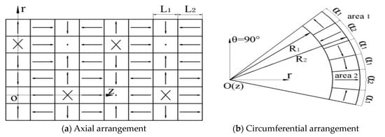
Figure 1.
New permanent magnet array model.
This new arrangement is not only innovative in theory, but also has broad prospects in practical applications. The advantages of this model mainly include the following aspects: Firstly, the parallel magnetization makes the magnetic field stable and can provide a reliable magnetic field environment for various applications. Secondly, the alternating periodic arrangement of single permanent magnets in different arrangement directions and permanent magnets of specific sizes makes the magnetic field distribution more complex, diverse, and uniform, which can meet the special needs of magnetic fields in different application scenarios. Furthermore, the periodic arrangement of the circumferential and axial directions makes the magnetic field have a certain regularity, which is convenient for the analysis and control of the magnetic field. However, the model also has some shortcomings. On the one hand, the complex arrangement of permanent magnets may increase the difficulty and cost of manufacturing. On the other hand, due to the complexity of the magnetic field, the analysis and optimization of the magnetic field may require more complex calculation methods and tools.
By changing the permanent magnet diameter, circumference, and axial geometry, the magnetic roller is optimized to determine the best physical and sorting parameters of the magnetic roller, so as to increase the magnetic flux density at the axial peak and trough of the magnetic field of the magnetic roller and improve the separation ability of non-ferrous metal blocks.
3. Research on the Magnetic Field of Magnetic Rollers Based on Circulation
The magnetic field is a complex physical phenomenon, and its characteristics are difficult to perceive intuitively. The theoretical calculation and formula are like accurate detectors, which can go deep into the microscopic level of the magnetic field and reveal its internal operating mechanism. Through strict mathematical derivation and logical deduction, the key characteristics of the magnetic field, such as the intensity, direction, and distribution, can be quantitatively described from the basic principle of electromagnetism, and the influence of different parameters on the magnetic field can be discussed in depth, such as the size, arrangement, and material properties of permanent magnets. A specific formula system suitable for the magnetic field of the magnetic roller of the circumferential–axial periodic arrangement permanent magnet is gradually constructed, and the change trend of the magnetic field is accurately predicted, which provides a scientific basis for the optimal design and practical application of the magnetic roller.
A study of the magnetic field of magnetic rollers is based on the ring current. In order to obtain the change law of the magnetic field strength of permanent magnet rollers with an alternating circumferential–axial periodic arrangement, it is first necessary to study the magnetic field characteristics of radial, circumferential, and axial unidirectional magnetized single permanent magnets. From the Ampere molecular current theorem, it is possible to derive a parallel magnetized permanent magnet equivalent current model.
The equivalent current model of a single radially magnetized permanent magnet is shown in Figure 2. The total equivalent current is as follows:
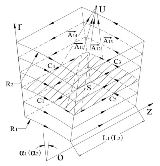
Figure 2.
Equivalent current model of radial magnetized permanent magnet.
In the formula, is the radial circulation density per unit length of a single radially magnetized permanent magnet; R1 and R2 are the radial dimensions of a single permanent magnet.
From the planar current-carrying coil magnetic moment model, the total magnetic moment m inside a single radially magnetized permanent magnet is as follows:
where the vector is the magnetic moment of a single toroidal coil; is the area of the mid-section of a single permanent magnet orthogonal to the r-axis; and is the unit vector in a right-handed helical relationship with the current direction.
This results in a magnetization strength of
where is the magnetization intensity of a single radially magnetized permanent magnet, which is a constant vector for uniform magnetization; is the volume of a single permanent magnet.
According to the Biot–Savart law, the magnetic flux density generated by the current element at any point in space is as follows:
where is the vacuum permeability; the vector is the circulating path microlinear element; the vector is the vectorial diameter of the taken linear element to the point .
Consider the relationship between the right-angle coordinate system and the column coordinate system as follows:
The flux density at the point outside a single radially magnetized permanent magnet can be expressed as
where , , are the unit vectors of parallel axes in the Cartesian coordinate system; , , , are
Similarly, the equivalent current model of a single circumferentially magnetized permanent magnet is shown in Figure 3 and the magnetic flux density of its external point is :
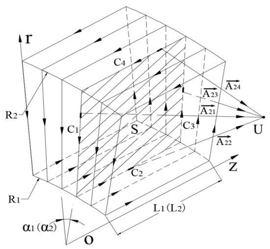
Figure 3.
Equivalent current model of circumferential magnetized permanent magnet.
In the formula, , , , are
Similarly, the equivalent current model of a single axially magnetized permanent magnet and the magnetic flux density of its external point shown in Figure 4 can be obtained as follows:
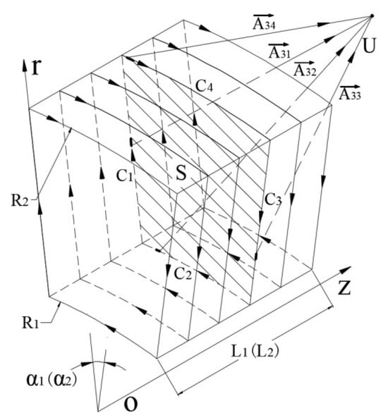
Figure 4.
Equivalent current model of axially magnetized permanent magnet.
In the formula, , , , are
Based on the construction of the equivalent current model of a single permanent magnet with different magnetizing directions and the calculation of the equivalent current, the characteristics of the external magnetic field of a single magnetized permanent magnet can be calculated, while the magnetic field of the external area of the magnetic roll can be regarded as the result of the joint action and contribution of multiple single permanent magnets with different magnetizing directions, except that the boundary conditions of the end areas on both sides of the roll are different from those of the non-end areas, which determine the characteristics of the magnetic field of the external area of the magnetic roll.
As shown in Figure 5, without loss of generality, the magnetic flux density of any point in the non-end region outside the magnetic roller is the result of the joint contribution of nine single permanent magnets determined by the magnetization direction in the adjacent region. Then, the magnetic flux density of point V is as follows:
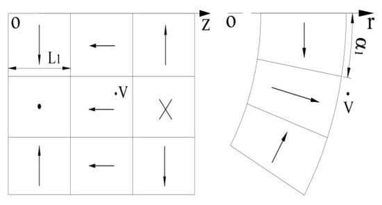
Figure 5.
Model of non-end region outside magnetic roller.
As shown in Figure 6, the magnetic flux density of at any point in the outer end region of the magnetic roller is the result of the joint contribution of six single permanent magnets with determined magnetization directions in the adjacent region. Then, the magnetic flux density at V point is as follows:
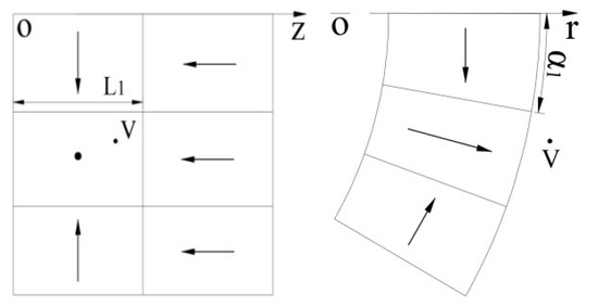
Figure 6.
Model of outer end region of magnetic roller.
So far, calculations can be made to obtain the magnetic roller external magnetic field change rule.
4. Magnetic Roll Magnetic Field Study Based on Magnetic Scalar Potentials
In order to further understand the pattern of changes in the magnetic field of the new arrangement of permanent magnet rolls, it is assumed that the magnetization intensity of a single permanent magnet magnetized in parallel in any direction is equal, that the relative permeability of the materials used in the support rolls of the permanent magnets and the connectors between the permanent magnets and the support rolls is infinite, and that there are no gaps between the permanent magnets or between the permanent magnets and the support rolls.
The divergence of the passive field is 0 by Gauss’s law of magnetism, so it is within the magnetic field of the magnetic rollers:
where is the magnetic flux density; is the divergence of .
The magnetic field strength is expressed by the magnetic scalar potential as
where is the magnetic field strength; φ is the magnetic scalar potential; ∇φ is the gradient of φ; , , are the unit vectors parallel to the coordinate axes in the cylindrical coordinate system.
Regions 1 and 2 are the external region of the magnetic roll surface and the internal region of the permanent magnet, respectively, as shown in Figure 1b. The flux densities and magnetic field strengths in areas 1 and 2 satisfy the relationship
where , are the flux densities in regions 1 and 2; H1, H2 are the magnetic field strengths in regions 1 and 2; is the magnetization strength of permanent magnets; , are the permeabilities in air and permanent magnets.
Substituting Equations (15) and (16) into Equation (14), the magnetic scalar potentials in regions 1 and 2 satisfy the following:
where , is the magnetic potential in regions 1 and 2; is the magnetization strength of permanent magnet array roll; is the divergence of .
In the column coordinates, the magnetization intensity can be expressed as
where , , are the r, θ, z direction magnetization intensity components.
The magnetization intensity of the permanent magnet array rollers is observed to change discontinuously, but periodically. Through the Fourier transform, the magnetization intensity component of the permanent magnet array roll is therefore
of which
where i, j is a non-zero natural number, , .
From Equation (18), we can obtain the magnetic potential φ1 and φ2, and then through Equation (16), we can obtain the solutions of the magnetic field strength and in the regions 1 and 2.
The special solutions of and can be determined from the boundary conditions of Equation (24) and the continuity theorem of the magnetic flux in regions 1 and 2.
In the formula, , are the magnetic field strengths of regions 1 and 2; is the magnetization strength of the permanent magnet array rollers.
5. Finite Element Analysis of New Permanent Magnet Array Roller
The CAE simulation tool is utilized to construct the magnetic rolls of the present study with 36 and 21 permanent magnets in the circum–axial direction, respectively, where R1 = 80 mm, R2 = 110 mm, α1 = α2 = 10, and L1 = L2 = 30 mm.
Figure 7 illustrates the finite element simulation of the magnetic flux density mode of the magnetic roller at a distance of 115 mm from the center of the magnetic roller. Figure 8 depicts the single-cycle radial–circumferential flux density change rule at a distance of 115 mm from the center of the magnetic roller. The peak values of the radial–circumferential flux density are 0. At a distance of 120 mm from the center of the magnetic roller, the single-cycle radial–circumferential flux density change rule is shown in Figure 9, with peak values of radial–circumferential flux density of 0.55 T and 0.35 T, respectively. The peak values of the radial–peripheral magnetic flux density are 0.55 T and 0.35 T, respectively.
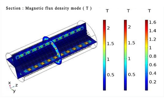
Figure 7.
Flux density mode.
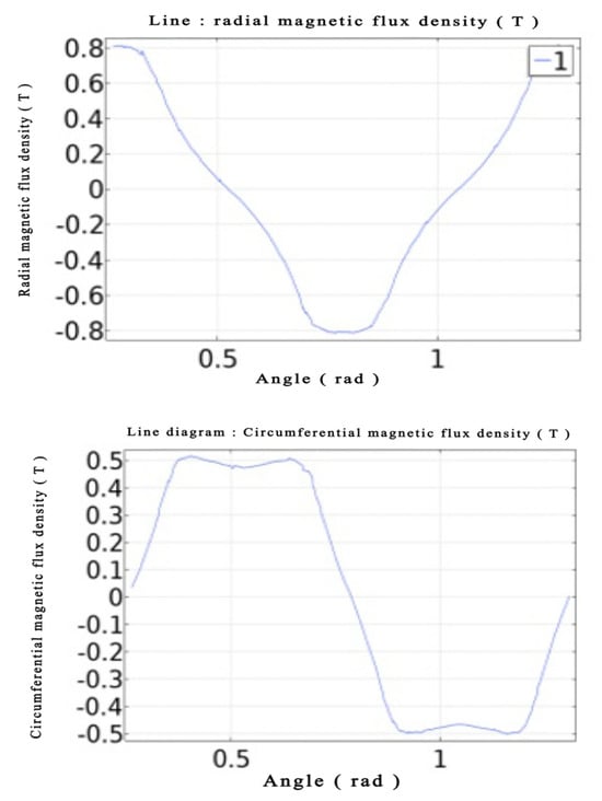
Figure 8.
At r = 115 m, Radial and circumferential flux density.
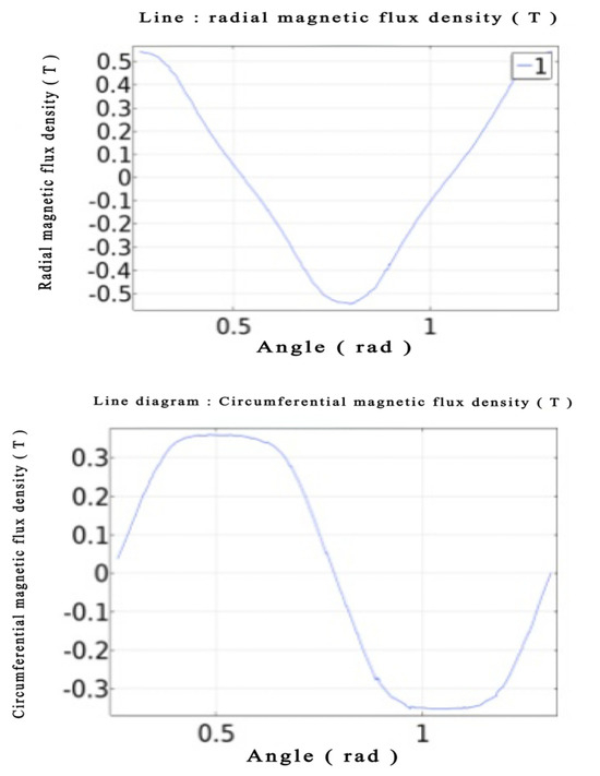
Figure 9.
At r = 120 m, Radial and circumferential flux density.
The peak radial–peripheral flux densities of the Halbach array rolls at r = 115 mm from the roll center are 0.62 T and 0.70 T for the same roll geometry and the same number of permanent magnets in the circumferential direction. For a given number of permanent magnets, the peak radial–peripheral flux density of the Halbach array roll is 0.62 T and 0.70 T at r = 115 mm, and the peak radial–peripheral flux density of the Halbach array roll is 0.44 T and 0.45 T at r = 120 mm from the roll center. The axial flux density of the roller in this study is sinusoidal, with peaks and valleys of flux density that are stronger than those of the Halbach array roll. This results in a larger eddy current force during the separation process, which is more convenient for the separation of large-size crushed Cu-Al parts of scrap cars.
6. Conclusions
- (1)
- In this paper, a new type of permanent magnet magnetic roller model is proposed through a specific permanent magnet arrangement. A single permanent magnet is magnetizing in parallel. Every four permanent magnets in the axial direction is an arrangement period, and every six permanent magnets in the circumferential direction is an arrangement period. The calculation mathematical model of the magnetic field of the magnetic roller is obtained by constructing the equivalent circulation model of a single permanent magnet and solving the magnetic scalar potential equations.
- (2)
- By changing the permanent magnet diameter, circumference, and axial geometry, the magnetic roller is optimized to determine the best physical and sorting parameters of the magnetic roller, thereby increasing the magnetic flux density at the magnetic field axial peak and trough of the magnetic roller, realizing the optimization of the magnetic roller and improving the separation ability of non-ferrous metal blocks.
- (3)
- By constructing the equivalent current model of a single permanent magnet and using the finite element simulation software, the distribution law of the external magnetic field of the magnetic roller is studied. On the basis of constructing the equivalent current model of a single permanent magnet with different magnetization directions and calculating the equivalent current, the characteristics of the external magnetic field of a single magnet are calculated. The magnetic field of the external area of the magnetic roller can be regarded as the interaction of multiple single permanent magnets with different magnetization directions with different boundary conditions on both sides of the magnetic roller and the non-end area. Therefore, the characteristics of the magnetic field in the external area of the magnetic roller and the optimal geometric parameters of the magnetic roller are determined to achieve a good separation effect. And it is more conducive to the separation of large-sized broken copper and aluminum parts of scrapped automobiles.
- (4)
- The axial direction of the new permanent magnet magnetic roller is also arranged periodically, which enhances the magnetic field strength and action distance of the external magnetic field of the magnetic roller. In the separation process, a greater eddy current force can be generated, which is more conducive to the separation of large-scale broken copper and aluminum parts of scrapped automobiles. The research results provide a theoretical basis for the separation of broken copper and aluminum parts of scrapped automobiles.
Author Contributions
Conceptualization, M.J. and Y.J.; methodology, Y.J.; verification, Y.Z., Z.L. and H.W.; formal analysis, Y.J.; investigation, Y.Z.; resources, Y.J.; data monitoring, M.J.; writing—original preparation, X.L.; writing—review and editing, X.L.; visualization, Y.Z.; supervision, Y.Z.; project management, Z.L. and H.W.; funded. All authors have read and agreed to the published version of the manuscript.
Funding
This research was supported by the following projects: Frontier Research Team of Kunming University 2023; National Natural Science foundation of China (52205374). This research was supported by the Yunnan Province Science and Technology Department (202101BA070001-157); the Special Basic Cooperative Research Programs of Yunnan Provincial Undergraduate Universities’ Association (202101BA070001-253).
Data Availability Statement
The original contributions presented in the study are included in the article, further inquiries can be directed to the corresponding author.
Conflicts of Interest
Author Mingjiang Jiang was employed by QingLing Motors (Group) Co., Ltd. The remaining authors declare that the research was conducted in the absence of any commercial or financial relationships that could be construed as a potential conflict of interest.
References
- Gao, X.; Wu, M.; Zhao, G. Recycling technology and development direction of waste lithium ion batteries are reviewed. Trans. Nonferrous Met. Soc. China 2024, 1–32. [Google Scholar]
- Fang, J.; He, Y.; Zhuge, X.; Luo, Z.; Luo, K.; Ding, Z.; Liu, X.; Li, Y. All-metal recovery from spent Ni-MH batteries based on electrolysis of sodium sulfate solution. Trans. Nonferrous Met. Soc. China 2023, 33, 3860–3870. [Google Scholar] [CrossRef]
- Cho, S.-J.; Jang, H.-N.; Cho, S.-J.; Yoon, Y.-S.; Yoo, H.-M. Material Recycling for Manufacturing Aggregates Using Melting Slag of Automobile Shredder Residues. Materials 2023, 16, 2664. [Google Scholar] [CrossRef] [PubMed]
- Xian, Y.; Tao, Y.; Ma, F.; Zhou, Y. Recovery of Metals from Heat-Treated Printed Circuit Boards via an Enhanced Gravity Concentrator and High-Gradient Magnetic Separator. Materials 2021, 14, 4566. [Google Scholar] [CrossRef] [PubMed]
- Kamura, K.; Makita, R.; Uchiyama, R.; Tanaka, H. Examination of metal sorting and concentration technology in landfill mining–with focus on gravity and magnetic force sorting. Waste Manag. 2022, 141, 147–153. [Google Scholar] [CrossRef]
- Aleksandrova, T.; Nikolaeva, N.; Afanasova, A.; Chenlong, D.; Romashev, A.; Aburova, V.; Prokhorova, E. Increase in Recovery Efficiency of Iron-Containing Components from Ash and Slag Material (Coal Combustion Waste) by Magnetic Separation. Minerals 2024, 14, 136. [Google Scholar] [CrossRef]
- Ye, F.; Deng, H.; Guo, Z. Separation mechanism and experimental investigation of pulsating high gradient magnetic separation. Results Phys. 2023, 49, 106482. [Google Scholar] [CrossRef]
- Lan, M.; He, Z.; Hu, X. Optimization of Iron Recovery from BOF Slag by Oxidation and Magnetic Separation. Metals 2022, 12, 742. [Google Scholar] [CrossRef]
- Cerrillo-Gonzalez, M.d.M.; Villen-Guzman, M.; Rodriguez-Maroto, J.M.; Paz-Garcia, J.M. Metal Recovery from Wastewater Using Electrodialysis Separation. Metals 2023, 14, 38. [Google Scholar] [CrossRef]
- Kercher, S.A.; Webb, M. Scrap processing by eddy current separation techniques. Resour. Conserv. 1982, 8, 61–74. [Google Scholar] [CrossRef]
- Van Der Valk, H.J.L.; Braam, B.C.; Dalmijn, W.L. Eddy current separation by permanent magnets part I: Theory. Resour. Conserv. 1986, 12, 233–252. [Google Scholar] [CrossRef]
- Fletcher, D.; Gerber, R.; Lawson, P.; Boehm, J. Eddy-current separation of non-ferrous conductors and non-conductors: Theory and initial experiments. IEEE Trans. Magn. 1991, 27, 5375–5377. [Google Scholar] [CrossRef]
- Norrgran, D.A.; Wernham, J.A. Recycling and secondary recovery applications using an eddy-current separator. Miner. Metall. Process. 1991, 8, 184–187. [Google Scholar] [CrossRef]
- Rem, P.C.; Leest, P.A.; Van den Akker, A.J. A model for eddy current separation. Int. J. Min. Process. 1997, 49, 193–200. [Google Scholar] [CrossRef]
- Rem, P.C.; Beunder, E.M.; Van den Akker, A.J. Simulation of eddy-current separators. IEEE Trans. Magn. 1998, 34, 22802286. [Google Scholar] [CrossRef]
- Zhang, S.; Forssberg, E.; Arvidson, B.; Moss, W. Aluminum recovery from electronic scrap by High-Force eddy current separators. Resour. Conserv. Recycl. 1998, 23, 225–241. [Google Scholar] [CrossRef]
- Zhang, S.; Rem, P.C.; Forssberg, E. Particle trajectory simulation of two-drum eddy current separators. Resour. Conserv. Recycl. 1999, 26, 71–90. [Google Scholar] [CrossRef]
- Rahman, M.A.; Bakker, M.C.M. Sensor-based control in eddy current separation of incinerator bottom ash. Waste Manag. 2013, 33, 1418–1424. [Google Scholar] [CrossRef]
- Yu, G.; Li, M.; Wang, J. The development status and prospect of eddy current sorting of non-ferrous metals in retired automobiles. Mater. Bull. 2015, 29, 59–67. [Google Scholar]
- Li, J.; Jiang, Y.; Xu, Z. Eddy current separation technology for recycling printed circuit boards from crushed cell phones. J. Clean. Prod. 2016, 141, 1316–1323. [Google Scholar] [CrossRef]
- Wei, H.; Ran, H. Research and development of eddy current separator for recycling waste non-ferrous metals and research on conductor ejection trajectory. Non-Ferr. Met. (Benef. Part) 2020, 3, 114–118+125. [Google Scholar]
- Chen, D.; Liu, J.; Guo, S. Separation mechanism of eddy current in thin-walled special-shaped copper-aluminum parts of scrapped automobiles. Chin. J. Nonferrous Met. 2020, 30, 1406–1414. [Google Scholar]
- Wang, D.; Ma, X.; Zhi, X.; Zhang, S. Research review of scrap metals eddy current separation technology. Sens. Transducers 2013, 158, 242–248. [Google Scholar]
Disclaimer/Publisher’s Note: The statements, opinions and data contained in all publications are solely those of the individual author(s) and contributor(s) and not of MDPI and/or the editor(s). MDPI and/or the editor(s) disclaim responsibility for any injury to people or property resulting from any ideas, methods, instructions or products referred to in the content. |
© 2024 by the authors. Licensee MDPI, Basel, Switzerland. This article is an open access article distributed under the terms and conditions of the Creative Commons Attribution (CC BY) license (https://creativecommons.org/licenses/by/4.0/).