Abstract
Well deviation is a prevalent problem in deep oil and gas exploration, leading to a significant increase in drilling costs. The conventional bottom-hole assembly (BHA) anti-deviation design method does not consider the impact of the BHA structure on lateral vibration. This paper proposes an integrated BHA design method that takes into account both anti-deviation and vibration reduction. This method evaluates the BHA’s anti-deviation ability using the drilling trend angle. A negative value of the drilling trend angle indicates that the BHA can correct well deviation. A finite element linearized dynamics method is used to evaluate the lateral vibration intensity of the BHA. This method involves calculating the bending displacement caused by mass imbalance and then determining the magnitude of the bending strain energy based on this displacement. The structural factors affecting the anti-deviation ability and potential lateral vibration intensity of pendulum BHAs and bent-housing mud motor (BHMM) BHAs were studied, and field tests were conducted for verification. The research shows that for pendulum BHAs, the factor that has the greatest impact on anti-deviation ability and vibration intensity is the distance from the stabilizer to the drill bit. For BHMM BHAs, the length of the short drill collar has a significant impact on the vibration intensity. Compared with current design methods, the mechanical specific energy (MSE) of the single stabilizer pendulum BHA decreased by 12%, while the MSE of the BHMM BHA decreased by 26.4%. Both decreases indicate a reduction in vibration intensity. This study will help to further increase drilling speed while preventing well deviation.
1. Introduction
Drilling a vertical wildcat well is essential for evaluating oil and gas reservoirs. Reducing its drilling cost can accelerate the exploration and development process. Maintaining verticality is usually difficult for deep and ultra-deep vertical wells. The primary reason for well deviation is that the strata are not horizontal, but rather inclined. This inclination is known as the formation dip. The drilling speed is often faster in the vertical strata direction than in the parallel strata direction. Typically, the greater the formation dip, the more substantial the well deviation [1]. Deep and ultra-deep wells intersect with more strata, thus increasing the probability of encountering a large inclined formation. To manage well deviation, the driller may sometimes need to decrease the weight on the bit (WOB) to keep the verticality of the drill bit. This, however, can lower the drilling speed. Therefore, improving drilling speed while controlling well deviation is always an important research topic.
The solution to the problem of well deviation mainly involves the use of anti-deviation bottom-hole assemblies (BHAs). Currently, there are two types of anti-deviation BHAs, namely, active anti-deviation BHAs and passive anti-deviation BHAs. Active anti-deviation BHAs refer to vertical drilling systems such as Schlumberger’s Power V. These systems are a variant of the rotary steerable system, offering benefits such as effective anti-deviation capabilities and adaptability to large formation dips [2]. However, a potential drawback is their high cost. Passive anti-deviation BHAs prevent deviation by arranging the structure of the bottom drilling tools reasonably. Common types include the pendulum BHA and the bent-housing mud motor (BHMM) BHA [3]. The primary advantage of passive anti-deviation BHAs is their low cost. However, they cannot adapt well to large formation dips, which is a significant disadvantage.
The key to successful anti-deviation drilling is the reasonable design of the drilling BHA structure according to the characteristics of the formation. For this reason, some theories have been proposed to evaluate the anti-deviation ability of the drilling BHA, including the three-point circle method [4,5], limiting curvature method [6], and balance trend method [7,8]. The three-point circle method estimates the build rate of the BHA based on geometric relationships. However, it does not consider the force and deformation of the drill string or the characteristics of the formation. The limiting curvature method considers the force and deformation of the drilling tool and the geometric shape of the wellbore, but still does not consider the characteristics of the drill bit and the formation. The balance trend method takes into account a wide range of factors, such as formation dip, formation anisotropy, bit anisotropy, bit lateral force, and bit tilt angle. It has been proven by drilling practice to be the most reliable method for predicting the build rate [9]. Consequently, this article uses the balance trend method to evaluate the build or drop ability of the BHA.
The use of either the limiting curvature method or the balance trend method is inherently connected to the modelling of the BHA. Currently, several BHA modeling methods are available, including finite element methods [10,11,12,13], beam-column theory [14,15,16] and other numerical methods [17,18,19,20]. One advantage of the finite element method is that it can be used for both static analysis and linearized forced frequency response analysis.
The existing method for designing anti-deviation BHAs often overlooks the issue of vibrations caused by different BHA structures. The mainstream anti-deviation BHA design prioritizes maximizing anti-deviation capability. However, it’s often possible to meet well deviation control requirements by moderately reducing the anti-deviation ability, which can significantly decrease the BHA’s vibration level. In other words, the designs for anti-deviation and anti-vibration of BHA are treated separately. However, Bailey et al. [21,22] showed that different BHAs have varying abilities to induce vibration. The more stable the BHA, the lower the drilling energy consumption. Therefore, if anti-deviation and anti-vibration designs were integrated seamlessly, drilling speed could be further increased through reasonable anti-vibration designs for vertical drilling BHAs.
Current research on reducing BHA vibration mainly focuses on two aspects, namely, the vibration related to the rotary steerable system [23] and the vibration related to reamer drilling [24], rarely involving the vibration of passive anti-deviation BHAs. In terms of vibration modes, high-frequency torsional vibration [25] and coupled vibration [26] have become hot research topics in recent years. Additionally, some studies focus on improving the vibration resistance of BHA by employing new materials, including high-strength aluminum alloys [27,28] and fiber-reinforced polymer composites [29].
This article proposes an integrated BHA design method to maintain verticality and prevent lateral vibrations at the same time. It involves using the finite element method for BHA static analysis, the balance trend method to evaluate the BHA’s anti-deviation capability, and the forced frequency response method for BHA vibration analysis.
2. Methods
2.1. BHA Modeling and Anti-Deviation Ability Evaluation
According to the balance trend method [8], to calculate the build rate of a BHA, two processes are needed. The first process is to perform a static analysis of the BHA to obtain the bit lateral force and tilt angle. Then, the lateral force and tilt angle of the drill bit are brought into the second process, which is the drill bit–formation interaction model [7], to calculate the drilling trend angle. In the first process, the BHA is placed in a wellbore with an assumed curvature; if the calculated drilling trend angle equals zero, the pre-assumed curvature is the true build rate of the BHA. If the drilling trend angle is less than zero, the well inclination will decrease. Otherwise, the well inclination will increase.
Since Xi et al. [3] have already detailed the calculation process of the drilling trend angle, this work will focus on introducing the finite element analysis of BHAs, particularly the method for bent-housing motors.
In finite element analysis, the drill string is discretized using a space Euler–Bernoulli beam with two nodes and six degrees of freedom. The static balance equation of the system can be written as:
where Fw is the equivalent node force from the drill string/wellbore contact; Fin is the internal force, formed by first performing the element analysis, then assembling it; Q is the equivalent node force of gravity; Fext is the external force, which is used to apply WOB and torque on the bit; and u is the system displacement vector.
Using the Newton–Raphson method to solve Equation (1), the original equation can be rewritten in the following form:
where Kt is the tangent stiffness matrix; KC is the contact stiffness matrix; Δu is the displacement increment in step i; and i is the order of analysis.
Kt can be obtained by deriving the displacement through internal force:
KC can be obtained by seeking the Jacobian matrix of FW; for details, please refer to Wilson [30].
As shown in Figure 1, the BHMM differs from the drill collar because it contains a structural bending angle and tool face orientation. This work uses a coordinate transformation method to deal with these features.
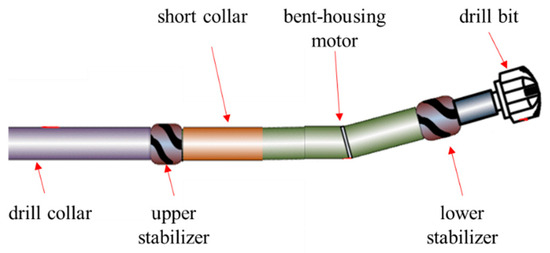
Figure 1.
Diagram of a BHMM BHA for vertical drilling.
In Figure 2, V3 represents the axial direction of the inclined straight wellbore, V2 represents the high-side direction of the wellbore, the x axis represents the axial direction of the part below the bend of the motor before deformation, the green line represents the part below the bend of the motor before deformation, point o represents the bend position, ΦBA is the size of the bending angle, and the red line represents the part below the bend of the motor after deformation.
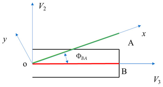
Figure 2.
Schematic diagram of BHMM coordinate transformation.
Element analysis can be conducted on the part below the bending point in the oxy coordinate system to obtain the element stiffness matrix and equivalent node force. Then, the results can be converted to the global coordinate system, oV2V3. For example, consider the conversion of the element node load Qe in the local coordinate system (oxy) to Qg in the global coordinate system (oV2V3):
where γ is the tool face orientation.
By solving Equation (2), we can obtain the deformation and force of the BHA and obtain the lateral force and tilt angle of the drill bit.
2.2. Forced Vibration Analysis Methods for Vertical Drilling BHAs
Linearized dynamic methods are often used to study the dynamic characteristics of BHAs, especially to evaluate the potential vibration intensity of BHAs [31]. Linearized dynamics refers to the application of excitation based on the static equilibrium position of the BHA, specifically studying its slight dynamic displacement. Among the various linearized dynamics methods, forced frequency response analysis can calculate responses at any speed. When the excitation amplitude and damping environment are correctly assigned, the calculated dynamic displacement response closely aligns with the actual situation.
According to the theory of Burgess et al. [32], the BHA part from the drill bit to the upper tangent point is taken as the research object, and the linearized dynamic equation of the BHA system can be written as:
where M is the mass matrix; C is the damping matrix; K is the total stiffness matrix; FC and FS, respectively, represent the cosine and sine excitation forces; ω is the frequency of the excitation force; and t is time.
The method of Dykstra [33] is used to calculate the mass matrix, M, and the damping matrix, C. Assume the displacement solution, u, has the following form:
Substitute Equation (7) into Equation (6) to obtain the following linearized system:
Mass eccentricity is a source of BHA vibration. The centrifugal force resulting from mass eccentricity can be expressed as follows:
where ωds is the rotational speed of the drill string; Fimb is eccentric force; m indicates the linear mass of the element; and e represents the mass eccentricity.
The solution of Equation (9) can obtain the dynamic displacement amplitude of BHAs, and the resonance rotational speed of BHAs can be determined according to the dynamic displacement curve. At the same time, the dynamic bending moment of BHA can be calculated based on the dynamic displacement.
2.3. Integrated Anti-Deviation and Anti-Vibration BHA Design Method
Potential BHA vibration intensity can be quantified using vibration indices [21,31], and the most effective evaluation index is the BHA bending strain energy. The BHA bending strain energy has the highest covariance with drilling mechanical specific energy (MSE). For the same formation, the larger the MSE, the more energy is consumed in drilling, otherwise, it proves that the drilling efficiency is higher. The bending strain energy is defined as:
where SE is the bending strain energy per length; L is the length of the BHA from the drill bit to the upper tangent point; N is the number of discretized elements; M is the bending moment; l is the element length; E is the Young’s modulus; and I is the moment of inertia.
The integrated design process for anti-deviation and anti-vibration purposes proposed in this work is shown in Figure 3. First, select the type of anti-deviation BHA based on the formation dip and wellbore diameter. In other words, choose between the pendulum BHA or the BHMM BHA. For example, for a 215.9 mm wellbore, it is recommended to choose a BHMM BHA when the formation dip is greater than 7°. Second, preliminarily design several anti-deviation BHA structures for further selection. Third, calculate the drilling trend angle of the alternative BHAs, and exclude those BHAs with a drilling trend angle greater than zero. Fourth, perform a linearized dynamic analysis on the remaining BHAs, calculate their SEs, and sort them. Finally, choose the BHA with the smallest bending strain energy.
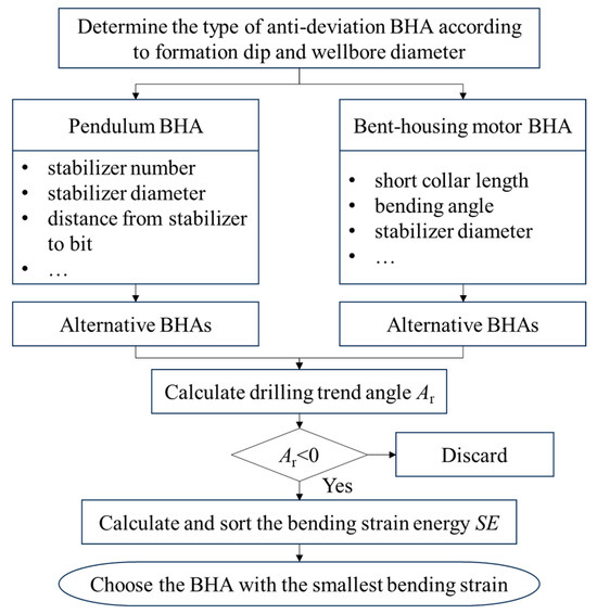
Figure 3.
Flowchart for integrated BHA design with anti-deviation and anti-vibration features.
In this study, MSE is used to confirm whether the optimized BHA design has effectively reduced downhole lateral vibrations. To make a quantitative comparison, the footage weighted average MSE is defined as follows:
where MSEfw is the footage weighted MSE and ΔD is the depth interval.
3. Results and Discussions
In this section, we study the structural factors that significantly influence the anti-deviation ability and vibration intensity of both pendulum and bent-housing motor BHAs. Based on the research results, we designed different BHA structures and conducted field trials. In all linearized dynamics analyses, the rotation speed of the top drive or rotary table is set to 60 to 140 revolutions per minute (RPM), which is the most used speed range on site.
3.1. Important Design Factors of Pendulum BHA
The anti-deviation ability and vibration intensity of the pendulum BHA may be influenced by factors such as the number and diameter of the stabilizers and the distance from the stabilizer to the drill bit. In this section, the basic structure of the pendulum BHA being studied is: 215.9 mm drill bit + 177.8 mm × 9.25 m collar × 2 + 1.524 m stabilizer + 177.8 mm drill collar.
First, the impact of the structural design of the single-stabilizer pendulum (SSP) BHA on anti-deviation and vibration intensity was studied. Figure 4 shows the bending strain energy of the SSP BHA with different stabilizer diameters. It is observed that the bending strain energy per length of the BHA increases as the diameter of the stabilizer decreases. The total bending strain energy per length for the 214 mm stabilizer is 4.11 × 10⁻³ N. However, for the 208 mm stabilizer, it can increase to 6.99 × 10⁻³ N, representing a 70.1% increase.
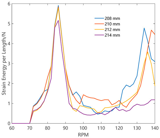
Figure 4.
The bending strain energy of an SSP BHA with different stabilizer diameters.
Figure 5 illustrates the variations in lateral force and the drilling trend angle for the SSP BHA under different stabilizer diameters. The diagram shows that as the stabilizer diameter decreases, the lateral force decreases, and the drilling trend angle gradually approaches zero. When the drilling trend angle approaches zero, the anti-deviation ability vanishes. If the drilling trend angle is greater than zero, the BHA switches to building inclination. Therefore, the changing trends of both indicate that the anti-deviation ability of this BHA is decreasing.
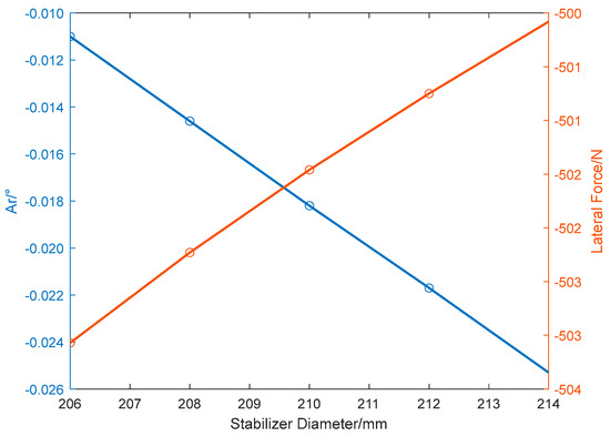
Figure 5.
Lateral force and drilling trend angle of an SSP BHA with different stabilizer diameters.
Figure 6 illustrates the bending strain energy of an SSP BHA with different stabilizer positions. The bending strain energy of the BHA increases from 19.26 m to 23.26 m, with the energy at 23.26 m significantly exceeding values at other distances. When the distance from the stabilizer to the drill bit extends from 19.26 m to 23.26 m, the bending strain energy increases by 400%. This suggests that the distance between the stabilizer and the drill bit should not be too large. Compared to 23.26 m, the bending stain energy of the BHA at 25.26 m is smaller because a new contact point is generated between the stabilizer and the drill bit.
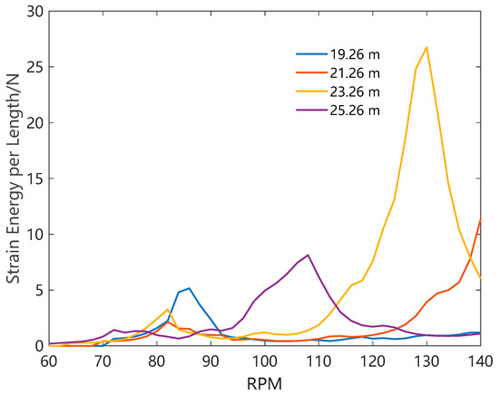
Figure 6.
The bending strain energy of an SSP BHA with different stabilizer positions.
Figure 7 displays the lateral force and drilling trend angle of the SSP BHA when the stabilizer is positioned differently. As the distance from the stabilizer to the drill bit increases, the absolute value of the lateral force acting on the drill bit increases, but this does not mean that the anti-deviation ability of the BHA is strengthening. The drilling trend angle shows that when the distance from the stabilizer to the drill bit exceeds 24 m, the BHA becomes an inclination-building BHA.
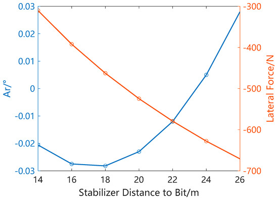
Figure 7.
Lateral force and drilling trend angle of an SSP BHA with different stabilizer positions.
Next, the impact of the structural parameters of the double-stabilizer pendulum (DSP) BHA on the anti-deviation effectiveness and vibration intensity was studied. At the drilling site, when using a DSP BHA, a small drill collar is often used between the two stabilizers to create the so-called flexible pendulum BHA. It is claimed that this design can enhance the anti-deviation ability. Figure 8 gives the bending strain energy of the DSP BHA when different sizes of the middle drill collar are used. The vibration caused by small drill collars (127.0 mm and 152.4 mm) is more intense than that caused by a regular-size drill collar (177.8 mm). When the drill collar size decreases from 177.8 mm to 127 mm, the bending strain energy increases by 39.1%.
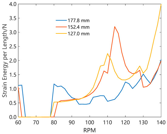
Figure 8.
The bending strain energy of a DSP BHA with different middle collar sizes.
Figure 9 shows the lateral force and the drilling trend angle of the DSP BHA when the middle drill collar uses different sizes. In the legend, Ib represents the anisotropy index of the drill bit. In absolute terms, the lateral force acting on the drill bit corresponding to the regular size drill collar is less than that of the small size drill collar. This is why the flexible pendulum BHA is considered to have a stronger anti-deviation ability. However, the drilling trend angle shows the opposite rule, that is, the anti-deviation ability of the small size drill collar is worse. In evaluating a BHA’s anti-deviation ability, the balance trend method considers more factors, such as the bit lateral force, bit tilt angle, formation dip, formation anisotropy index, and bit anisotropy index. This method is more reliable than just considering lateral force. Therefore, the traditional flexible DSP BHA design method is not scientific at all.
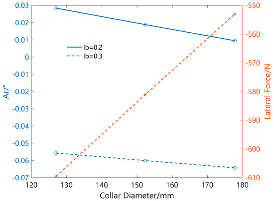
Figure 9.
Lateral force and drilling trend angle of a DSP BHA with different middle collar sizes.
In addition, an SSP BHA can correct deviation when the bit anisotropy index is 0.2, but a DSP BHA can only prevent deviation when the bit anisotropy index is 0.3. This indicates that a DSP BHA has more stringent requirements for bit selection. Therefore, an SSP BHA exhibits greater anti-inclination ability compared to DSP BHAs. During field tests, to prevent well inclination, we opted to conduct tests with SSP BHAs. Specifically, we studied the influence of an SSP BHA’s structural parameters on its MSE.
3.2. Important Design Factor of Bent Housing Mud Motor BHA
The BHMM BHA is the most effective passive anti-deviation drilling BHA, and its structure is shown in Figure 1. For this type of BHA, there is design confusion over whether to use a short drill collar and how long the short drill collar should be. In this section, the basic structure of the BHMM BHA being studied is: 215.9 mm drill bit + 172 mm × 8.5 m mud motor (1.25° bend angle, 213 mm on-motor stabilizer) + 0~3 m short drill collar + 1.524 m stabilizer + 177.8 mm drill collar.
Figure 10 shows the drilling trend angle of the BHMM BHA when using short drill collars of different lengths to adjust the distance from the upper stabilizer to the drill bit (the first point on the curve represents no use of any short drill collar). As the distance from the upper stabilizer to the drill bit increases, the drilling trend angle gradually increases and becomes a positive value, indicating that the anti-deviation ability of the BHMM BHA is decreasing. Therefore, to obtain the best anti-deviation ability, short drill collars should not be used, that is, the upper stabilizer should be directly connected to the mud motor.
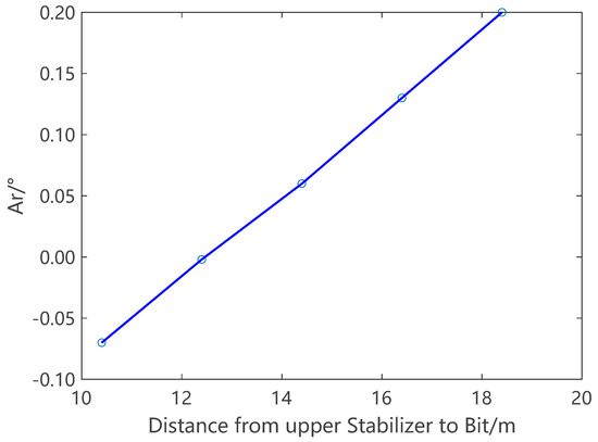
Figure 10.
The drilling trend angle of a BHMM BHA with different short collar lengths.
However, the experience of drilling engineers shows that using a certain length of short drill collar can also maintain verticality, and the drilling process is more stable, but this experience is not widely recognized and lacks theoretical proof. Figure 11 shows the bending strain energy of the BHMM BHA when using short drill collars of different lengths. When not using a short drill collar, the vibration intensity of the BHA is the highest (7.23 × 10⁻² N). Using a 2 m (2.63 × 10⁻² N) or 3 m (2.76 × 10⁻² N) short drill collar can achieve similar vibration reduction effects. This results in a 63.6% decrease in vibration compared to not using a short drill collar. Figure 10 shows that using a 2 m short drill collar can still maintain the anti-deviation result. Therefore, by appropriately adjusting the short drill collar length to meet anti-deviation needs, we can decrease the BHA’s vibration intensity.
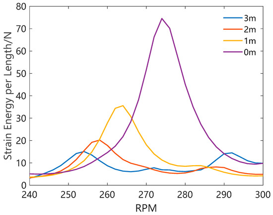
Figure 11.
The bending strain energy of a BHMM BHA with different short collar lengths.
3.3. Field Tests of the Design Method
To verify the integrated BHA design method for anti-deviation and vibration reduction proposed in this work, field tests were carried out in two vertical oil wells in an oilfield in Northwest China. Field tests were conducted in eight bit runs with a diameter of 215.9 mm, among which four bit runs used two types of pendulum BHA and four bit runs used two types of BHMM BHA. The structure of the first pendulum BHA design is: 215.9 mm drill bit + 172 mm × 8.6 m straight-housing mud motor + 177.8 mm × 9.25 m drill collar + 214 mm × 1.52 m stabilizer + 177.8 mm drill collar, marked as SSP BHA1 (used in two bit runs). The structure of the other pendulum BHA design is: 215.9 mm drill bit + 172 mm × 8.6 m straight-housing mud motor + 177.8 mm × 9.25 m drill collar + 4 m short drill collar + 214 mm × 1.52 m stabilizer + 177.8 mm drill collar, marked as SSP BHA2 (used in another two bit runs).
The stabilizer of the second pendulum BHA is located further from the drill bit. Many drilling engineers believe that increasing this distance can improve the anti-deviation effectiveness. This is because it increases the anti-deviation force exerting on the drill bit. Clearly, this reasoning is based on the idea that a larger anti-deviation force results in better anti-deviation effectiveness.
Other parameters in the design of pendulum BHAs are as follows: formation dip angle 6°, formation anisotropy index 0.98, bit anisotropy index 0.25. The drilling trend angle of SSP BHA1 is −0.0255 and the drilling trend angle of SSP BHA2 is −0.0084, indicating that both sets of BHAs can achieve anti-deviation. The unit length bending strain energy of SSP BHA1 is 3.61 × 10⁻³ N. Meanwhile, that of SSP BHA2 is 1.61 × 10⁻² N, which is 4.46 times greater than that of the first set. To maintain the comparability of MSE results, both BHAs are equipped with the same type of PDC drill bits. The WOB is maintained between 70 and 80 kN, and the mud flow rate is set at 30 L/s.
Field tests demonstrated that both SSP BHA1 and SSP BHA2 could maintain an inclination within 2°. In this study, WOB, torque, and the rate of penetration during drilling are obtained from the engineering logging database to calculate the MSE. Figure 12 shows the MSE curves corresponding to SSP BHA1 and SSP BHA2 in the same well section of two adjacent wells, and the curve corresponding to SSP BHA1 is slightly lower. The total footage of SSP BHA1 and SSP BHA2 is 626 m and 592 m, respectively. The average MSE of the two sets of BHAs is calculated with footage weighting, and it is found that the MSEfw (90.9 MPa) of SSP BHA1 is 12% lower than that (103 MPa) of SSP BHA2.
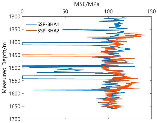
Figure 12.
The WMSE of SSP BHA1 and SSP BHA2 in the same formation.
For BHMM BHAs, the first structural design is: 215.9 mm drill bit + 172 mm × 8.6 m bent-housing mud motor (214 mm on-motor stabilizer, 1.0° bend angle) + 214 mm × 1.52 m stabilizer + 177.8 mm drill collar, marked as BHMM BHA1. The second structural design is 215.9 mm drill bit + 172 mm × 8.6 m bent-housing mud motor (214 mm on-motor stabilizer, 1.0° bend angle) + 177.8 mm × 2 m short drill collar+ 214 mm × 1.52 m stabilizer + 177.8 mm drill collar, marked as BHMM BHA2. The difference between the two designs is that the second design uses a 2 m long short drill collar.
The parameters used in the design process are as follows: formation dip angle 10°, formation anisotropy index 0.98, drill bit anisotropy index 0.30. The drilling trend angle of BHMM BHA1 is −0.0237 and the drilling trend angle of BHMM BHA2 is −0.0965, indicating that both sets of BHAs can achieve anti-deviation. The unit length bending strain energy of BHMM BHA1 is 7.23 × 10⁻² N. Meanwhile, the unit length bending strain energy of BHMM BHA2 is 2.63 × 10⁻² N, constituting 36.4% of the first set. Similarly, both BHMM BHAs are equipped with the same PDC drill bits to ensure the comparability of the results.
Field tests demonstrated that both BHMM BHA1 and BHMM BHA2 could maintain an inclination within 1.5°. The total footage of BHMM BHA1 and BHMM BHA2 is 685 m and 742 m, respectively. The MSEfw of BHMM BHA1 is 176.3 MPa. Meanwhile, the MSEfw of BHMM BHA2 is 129.7 MPa, which is 26.4% lower than that of BHMM BHA1. Figure 13 shows a comparison of the MSE curves of BHMM BHA1 and BHMM BHA2 drilling in the same formation.
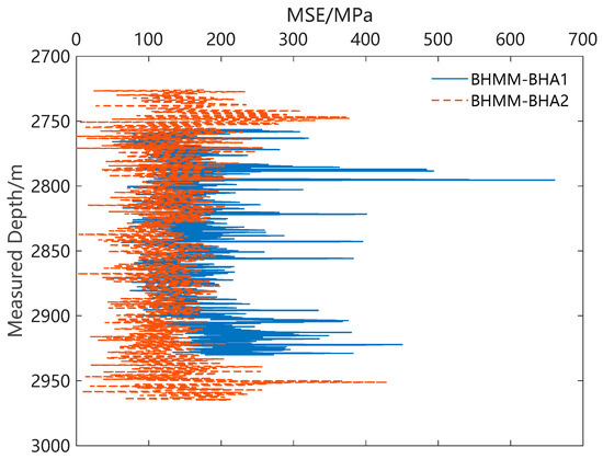
Figure 13.
The WMSE of BHMM BHA1 and BHMM BHA2 in the same formation.
The above comparison of MSE data shows that the proposed integrated design method in this work is feasible. It can reduce vibration and improve energy utilization, particularly for BHMM BHAs.
4. Conclusions
This article proposes an integrated BHA design method to achieve anti-deviation of vertical oil and gas wells and reduce lateral vibration intensity. For two typical BHAs, namely, pendulum BHAs and BHMM BHAs, the structural factors affecting their anti-deviation ability and vibration intensity were studied. Finally, field tests were conducted to verify the proposed method.
The main conclusions from this study are as follows. For pendulum BHAs, the distance from the stabilizer to the drill bit greatly affects the vibration intensity and the ability to prevent deviation; altering the distance between the stabilizer and the drill bit by 4 m can result in a 400% increase in bending strain energy, which is a factor that needs to be emphasized in design. SSP BHAs have a stronger anti-deviation ability than DSP BHAs. The traditional flexible pendulum DSP BHA design concept will increase the inclination-dropping force, but according to the drilling trend method, this design does not necessarily enhance the anti-deviation ability. The use and non-use of short drill collars significantly impact the bending strain energy of BHMM BHAs, and a decline of 63.6% can be achieved by using a 2 m short drill collar. A well-designed short drill collar length can effectively minimize vibration intensity, reduce drilling MSE, and enhance the utilization rate of drilling energy. Field tests confirmed the reliability of the method proposed in this paper, and the optimized BHMM BHA reduced the MSE by 26.4%.
The integrated BHA design method proposed in this article is specifically for PDC drill bits and lateral vibrations. If the well in question uses a roller cone bit, or if the primary vibration is not lateral but axial or stick-slip, the method proposed here may not reduce the vibration intensity and could potentially increase it. Future research will focus on developing BHA design methods to mitigate axial and stick-slip vibrations.
Author Contributions
Writing, methodology, Z.C.; Conceptualization, L.Z. and Z.H.; software, X.D.; project administration, Z.L.; investigation, resources, T.L. All authors have read and agreed to the published version of the manuscript.
Funding
This research received no external funding.
Data Availability Statement
The data used to support the findings of this study are available from the corresponding author upon request.
Acknowledgments
The authors thank CNOOC Ener Tech-Drilling & Production Co. for the support and the permission to publish this research.
Conflicts of Interest
Authors Zhong Cheng, Liang Zhang, Zhouzheng Hao, Xiangxiang Ding, were employed by CNOOC Ener Tech-Drilling & Production Co. The remaining authors declare that the research was conducted in the absence of any commercial or financial relationships that could be construed as a potential conflict of interest.
Abbreviations
| BHA | bottom-hole assembly |
| BHMM | bent-housing mud motor |
| DSP | double-stabilizer pendulum |
| MSE | mechanical specific energy |
| RPM | revolutions per minute |
| SSP | single-stabilizer pendulum |
| WOB | weight on bit |
References
- Tan, B.; Xu, Q.; Fu, Q. Research and Application of Air Drilling Key Technologies in Bozi Block, Xinjiang. Drill. Prod. Technol. 2021, 44, 13–16. [Google Scholar]
- Jones, S.; Feddema, C.; Castro, J.; Sugiura, J. Fully Mechanical Vertical Drilling System Delivers RSS Performance in Vertical Drilling Applications While Providing an Economical Alternative to Conventional Rotary Steerable Systems Set-Up for Vertical Hold Mode. In Proceedings of the IADC/SPE Drilling Conference and Exhibition, Fort Worth, TX, USA, 6–8 March 2016. [Google Scholar]
- Xi, C.; Zhang, W.; Zhang, N.; Chu, H. Study on factors affecting vertical drilling bottom hole assembly performance and a new bottom hole assembly design method considering formation uncertainties. Front. Energy Res. 2022, 10, 1073135. [Google Scholar] [CrossRef]
- Karlsson, H.; Brassfield, T.; Krueger, V. Performance Drilling Optimization. In Proceedings of the SPE/IADC Drilling Conference, New Orleans, LA, USA, 6–8 March 1985. [Google Scholar]
- Karlsson, H.; Cobbley, R.; Jaques, G.E. New Developments in Short-, Medium-, and Long-Radius Lateral Drilling. In Proceedings of the SPE/IADC Drilling Conference, New Orleans, LA, USA, 18–21 February 1989. [Google Scholar]
- Su, Y. Limiting curvature method and its application. Acta Pet. Sin. 1997, 18, 110–113. [Google Scholar]
- Ho, H.-S. Prediction of Drilling Trajectory in Directional Wells Via a New Rock-Bit Interaction Model. In Proceedings of the SPE Annual Technical Conference and Exhibition, Dallas, TX, USA, 27 September 1987. [Google Scholar]
- Shi, Y.; Guan, Z.; Zhao, H.; Huang, G. A new method for build-up rate prediction of bottom-hole assembly in well drilling. J. China Univ. Pet. 2017, 41, 85–89. [Google Scholar]
- Huang, W.; Wang, K.; Gao, D. A method for predicting the build-up rate of “push-the-bit” rotary steering tool. Nat. Gas Ind. 2021, 41, 101–106. [Google Scholar]
- Millheim, K.; Jordan, S.; Ritter, C.J. Bottom-Hole Assembly Analysis Using the Finite-Element Method. J. Pet. Technol. 1978, 30, 265–274. [Google Scholar] [CrossRef]
- Neubert, M.; Heisig, G.; Forstner, I.; Mounzer, F. Verification of an Advanced BHA Analysis Model with Downhole Bending Moment Measurements. In Proceedings of the SPE Asia Pacific Oil and Gas Conference and Exhibition, Jakarta, Indonesia, 5–7 April 2005. [Google Scholar]
- Wilson, J.K. Field Validation of a New BHA Model and Practical Case Studies in Unconventional Shale Plays, with a Framework for Automated Analysis for Operations Support. In Proceedings of the SPE/AAPG Eastern Regional Meeting, Pittsburgh, PA, USA, 7–11 October 2018. [Google Scholar]
- Greenwood, J.; Marck, J.; Nair, V.N.; Munguia, J. Drilling Performance Evaluation Using Advanced BHA Modeling and Field Validation. In Proceedings of the IADC/SPE International Drilling Conference and Exhibition, Galveston, TX, USA, 3–5 March 2020. [Google Scholar]
- Bai, J. Bottom Hole Assembly Problems Solved by Beam-Column Theory. In Proceedings of the International Petroleum Exhibition and Technical Symposium, Beijing, China, 16–24 March 1982. [Google Scholar]
- Bai, J.; Lin, X. Two-Dimensional Analysis of Bottom Hole Assembly by Beam-Column Theory. Acta Pet. Sin. 1985, 6, 75–84. [Google Scholar]
- Bai, J.; Huang, Z.; Liu, Y. Three-Dimensional Analysis of Bottom Hole Assembly by Beam-Column Theory. Acta Pet. Sin. 1989, 10, 60–66. [Google Scholar]
- Menand, S.; Sellami, H.; Tijani, M.; Stab, O.; Dupuis, D.; Simon, C. Advancements in 3D Drillstring Mechanics: From the Bit to the Topdrive. In Proceedings of the IADC/SPE Drilling Conference, Miami, FL, USA, 21–23 February 2006. [Google Scholar]
- Menand, S.; Mills, K.A.; Suarez, R. Micro Dogleg Detection with Continuous Inclination Measurements and Advanced BHA Modeling. In Proceedings of the Abu Dhabi International Petroleum Exhibition & Conference, Abu Dhabi, United Arab Emirates, 7–10 November 2016. [Google Scholar]
- Goicoechea, H.; Buezas, F.S.; Rosales, M.B. A non-linear Cosserat rod model for drill-string dynamics in arbitrary borehole geometries with contact and friction. Int. J. Mech. Sci. 2019, 157, 98–110. [Google Scholar] [CrossRef]
- Yu, F.; Huang, G.; Li, W.; Ni, H.; Huang, B.; Li, J.; Duan, J. Modeling lateral vibration of bottom hole assembly using Cosserat theory and laboratory experiment verification. Geoenergy Sci. Eng. 2023, 222, 211359. [Google Scholar] [CrossRef]
- Bailey, J.R.; Biediger, E.A.O.; Gupta, V.; Ertas, D.; Elks, W.C.; Dupriest, F.E. Drilling Vibrations Modeling and Field Validation. In Proceedings of the IADC/SPE Drilling Conference, Orlando, FL, USA, 4–6 March 2008. [Google Scholar]
- Bailey, J.R.; Lathi, H.; Tenny, M.J.; Payette, G.S.; Wang, L. BHA Lateral Vibration Chatter Impedes Application of Weight to Bit. In Proceedings of the IADC/SPE International Drilling Conference and Exhibition, Galveston, TX, USA, 3–5 March 2020. [Google Scholar]
- Wilson, J.K.; Heisig, G.; Freyer, C. HFTO Solved: Proven Mitigation of High Frequency Torsional Oscillations in Motor-Assisted Rotary Steerable Applications. In Proceedings of the IADC/SPE International Drilling Conference and Exhibition, Galveston, TX, USA, 7 March 2022. [Google Scholar]
- Dushaishi, M.F.A.I.; Stutts, D.S. Vibration analysis of simultaneous drilling and reaming BHA. J. Pet. Explor. Prod. Technol. 2020, 10, 3409–3417. [Google Scholar] [CrossRef]
- Sugiura, J.; Jones, S. Simulation and Measurement of High-Frequency Torsional Oscillation HFTO/High-Frequency Axial Oscillation HFAO and Downhole HFTO Mitigation: Knowledge Gains Continue by Using Embedded High-Frequency Drilling Dynamics Sensors. In Proceedings of the IADC/SPE International Drilling Conference and Exhibition, Galveston, TX, USA, 3–5 March 2020. [Google Scholar]
- Chen, S.; Propes, C.; Lanning, C.; Dunbar, B. Mechanisms and Mitigation of 3D Coupled Vibrations in Drilling with PDC Bits. In Proceedings of the SPE Annual Technical Conference and Exhibition, Dubai, United Arab Emirates, 21–23 September 2021. [Google Scholar]
- Belkacem, L.; Abdelbaki, N.; Otegui, J.L.; Gaceb, M.; Bettayeb, M. Using a superficially treated 2024 aluminum alloy drill pipe to delay failure during dynamic loading. Eng. Fail. Anal. 2019, 104, 261–273. [Google Scholar] [CrossRef]
- Cheng, J.; Yu, Y.; Sun, Y. Numerical analysis of whirl for drill string with aluminum alloy drill pipes in deep vertical well. Geoenergy Sci. Eng. 2023, 231, 212314. [Google Scholar] [CrossRef]
- Vedernikov, A.; Gemi, L.; Madenci, E.; Özkılıç, Y.O.; Yazman, Ş.; Gusev, S.; Sulimov, A.; Bondareva, J.; Evlashin, S.; Konev, S.; et al. Effects of high pulling speeds on mechanical properties and morphology of pultruded GFRP composite flat laminates. Compos. Struct. 2022, 301, 116216. [Google Scholar] [CrossRef]
- Wilson, J.K. Nonlinear Drillstring Modeling with Applications to Induced Vibrations in Unconventional Horizontal Wells. Ph.D. Thesis, Texas A&M University, College Station, TX, USA, 2017. [Google Scholar]
- Bailey, J.R.; Remmert, S.M. Managing Drilling Vibrations Through BHA Design Optimization. SPE Drill. Compl. 2010, 25, 458–471. [Google Scholar] [CrossRef]
- Burgess, T.M.; McDaniel, G.L.; Das, P.K. Improving BHA tool reliability with drillstring vibration models: Field experience and limitations. In Proceedings of the SPE/IADC Drilling Conference, New Orleans, LA, USA, 15–18 March 1987. [Google Scholar]
- Dykstra, M.W. Nonlinear Drill String Dynamics. Ph.D. Thesis, The University of Tulsa, Tulsa, OK, USA, 1996. [Google Scholar]
Disclaimer/Publisher’s Note: The statements, opinions and data contained in all publications are solely those of the individual author(s) and contributor(s) and not of MDPI and/or the editor(s). MDPI and/or the editor(s) disclaim responsibility for any injury to people or property resulting from any ideas, methods, instructions or products referred to in the content. |
© 2023 by the authors. Licensee MDPI, Basel, Switzerland. This article is an open access article distributed under the terms and conditions of the Creative Commons Attribution (CC BY) license (https://creativecommons.org/licenses/by/4.0/).