Abstract
The integration of distributed power generation mainly consisting of photovoltaic and wind power into active distribution networks can lead to safety accidents in grid operation. At the same time, climate change can also cause voltage fluctuations, direct current injection, harmonic pollution, frequency fluctuations, and other issues. To achieve economic and safe operation of the distribution network, an active distribution network-network planning model considering the dynamic configuration of energy storage system energy storage is constructed. This model focuses on energy storage batteries with high ease of use, high modularity, and strong mobility. The route location planning involving different load operating scenarios in spring, summer, autumn, and winter is constructed. The objective function includes the revenue from selling electricity in the distribution network, the expenditure on purchasing electricity in the distribution network, and the cost during the planned construction period. The constraints include three major constraints: distribution network operation, network topology, and energy storage system operation. Three numerical examples are set up to analyze the impact of energy storage system dynamic configuration on grid planning. The results confirmed the active distribution network-grid planning model for dynamic configuration of energy storage systems. Both Example 2 and Example 3 had 3 ESS configurations. Case 3 showed different access methods for ESS in different seasons. The access nodes for ESS in spring and winter were 4, 5, and 6, while the access nodes for summer and autumn were 3, 5, and 6. After applying the proposed method, the daily energy storage investment of commercial, residential, and industrial users gradually stabilized. The reliability of electricity consumption was improved, with an improvement rate of about 40%. The research has brought considerable economic benefits to distribution network operators. It has forward-looking academic value in the joint planning of grid structures and energy storage.
1. Introduction
Against the backdrop of continuous innovation in energy storage technology worldwide, countries and regions around the world are spending time and effort researching the planning and configuration of energy storage in distribution networks. To achieve the global goals of low-carbon environmental protection, energy conservation and emission reduction, and ensure the reliability and quality of distribution networks, the research on the introduction of distributed energy into distribution networks will become a new trend. To make it possible to integrate renewable energy into the distribution network, solve the traditional distribution networks being unable to achieve large-scale connection of new energy, and achieve effective utilization of power resources, the concept of Active Distribution Network (ADN) has been proposed by international power grid experts [1,2,3]. ADN adopts an active management mode to achieve Distributed Generation (DG), Energy Storage System (ESS), and customer bidirectional load control. It has positive significance in the utilization and penetration rate of renewable energy such as photovoltaic and wind energy in the distribution network. The key technology of ADN is energy storage technology. It can increase the consumption rate of renewable resources and reduce the pressure of electricity load. On the premise of mature development of ESS manufacturing technology, the introduction of distributed energy storage in the distribution network has positive advantages [4,5]. ADN can improve grid stability, reduce grid losses, and perform peak shaving and valley filling by utilizing ESS operation mode. At the same time, ESS managers can also obtain high economic benefits through time-of-use electricity prices or peak valley electricity prices, thereby achieving comprehensive utilization of multiple resources and a win-win situation for the community of interests [6,7]. The current energy storage planning and energy storage grid planning do not consider the configuration of the capacity and location factors of movable ESS in the distribution network. In the actual process, the optimal network structure is planned based on factors such as the load size and type of the operating scenario. The impact of optimal ESS configuration on grid planning under load and DG seasonal characteristics needs to be analyzed. Based on the above analysis, an ADN network planning model that considers the ESS energy storage dynamic configuration is constructed. Based on the analysis of network structure planning, this model considers the flexible configuration of energy storage in different scenarios of ADN. The role of ESS dynamic energy storage in ADN is maximized. It is expected to provide enormous practical and academic value for the cutting-edge development of ADN energy storage planning. The contribution of the research is mainly reflected in two aspects: designing an ADN grid planning model that considers the dynamic configuration of ESS energy storage. The model will focus on energy storage batteries with high ease of use, high modularity, and strong mobility as the research object, with a focus on exploring the objective function and constraint conditions. Secondly, analyzing the impact of optimal ESS configuration on grid planning under different load operating scenarios in summer, autumn, and winter, as well as the different site selection, capacity setting, and charging/discharging operation modes of energy storage, improvements were made based on the constraints of the spanning tree to achieve the selection of planned lines. The research is elaborated on the following four structures. The first part introduces the cutting-edge research status of ADN energy storage dynamic configuration and grid joint planning globally. The second part constructs an ADN network planning model that considers the ESS energy storage dynamic configuration. It focuses on introducing the ESS energy storage dynamic configuration and the corresponding network joint planning model for the distribution network. The third part analyzes the empirical application effect of the model through three examples. The fourth part summarizes the research results and proposes the next development direction of the research.
2. Related Works
With the rise of new equipment such as electric vehicles, ESS, DG, etc., there are more research reports on distribution network planning including ESS, DG, and charging stations. Zhang Y and other researchers analyzed a joint planning approach for battery energy storage and distributed generation in ADN. The purpose of this joint plan was to adjust the voltage to achieve optimal layout. Specifically, it was to optimize the charging and discharging process of the scheduling ESS and the reactive power of the inverter. The test results of the IEEE 33 node radial distribution system showed that the proposed joint planning could be used for voltage regulation in distribution networks [8]. Gao H et al. designed a two-stage distributed robust planning model to solve the joint planning problem of distributed energy sources in the unknown distributed power sources. This model analyzed different types of controllable loads, distributed energy storage systems, and photovoltaic power generation systems. The nonlinear programming problem was replaced with a mixed integer second-order cone programming problem. The test results of the 33-node system showed that the model could find the optimal planning decision under the worst-case probability distribution and minimizing the total cost [9]. Yan X et al. proposed a flexible dynamic optimization model that combined intelligent load and time scale ADN to address the current issues in the renewable resource utilization and load integration in distribution networks. This model could reduce the volatility of load and the overall cost of distribution network operators in the long term. In the short term, it solved the charge on the electricity demand side while improving the flexibility of the distribution network itself. For ordinary users, the reliability of power loads and the quality of electricity consumption were higher [10]. Wenzhi S et al. constructed a hierarchical energy optimization management model using the concept of multi microgrid operation. It was applied to ADN in different eating scenarios. The optimal energy allocation was achieved through an improved sparrow search algorithm. The test function results indicated that the model could achieve optimal configuration. It had good environmental and economic effects in various scenarios [11]. The penetration of renewable energy in the distribution network was gradually increasing. For this issue, Venkateswaran V B et al. proposed a planning method for energy storage units in distribution networks that was suitable for both normal and extreme situations. The elastic impact of this method on ESS was analyzed. The test results showed that this planning method could identify the optimal position of the ESS unit in the distribution network, while also maximizing the maximum power of the energy storage unit [12].
To address the network and traffic flow issues in current multi energy system planning, Xie S et al. proposed a planning framework that combined active allocation of resources such as networks, natural gas, and transportation. Convex relaxation was used to transform a programming model into a mixed integer second-order cone programming problem. The test results of four actual cases showed that the planning method could reduce energy loss by more than 5.6% and reduce traffic flow by about 25% [13]. Valencia A et al. proposed a mixed integer nonlinear programming model to analyze renewable distributed generators and novel battery ESS in medium and low voltage distribution systems. The method included selecting the optimal location of the device and finding the optimal path for battery ESS operation. The results of the IEEE 135 node testing system and the low voltage distribution system in 230 nodes confirmed that this method had strong robustness and effectiveness [14]. Santos S F et al. proposed a new dynamic distribution system reconfiguration model. This model considered the permeability of distributed renewable power sources and the uncertainty of energy storage and distribution systems, while also considering emission and switching costs. The switching cost not only included the switching of different scenarios, but also the cost of mechanism degradation during system operation. The IEEEE 119 node testing system results showed that the model could reliably reduce the energy demand rate by about 60% within 24 h. This coordinated planning model was crucial for the development of smart grids [15]. Esmaeeli M et al. proposed a planning method that combined technical and financial unknown risks to determine the optimal structure of distribution network structures. The planning cost of the distribution network system included technical risk cost, reliability cost, energy loss cost, maintenance cost, and investment cost. This method was suitable for testing system substations composed of 2 power load points and 52 power load points. It could reduce the accident probability and greatly control the cost investment of distribution network operators [16]. Wang D et al. constructed a two-layer network source coordination and expansion planning model to determine the capacity and location of distributed power sources, as well as explore planning solutions for high permeability of distributed energy distribution networks. The upper layer of this model optimized the access location, capacity, and network structure. A hybrid genetic algorithm was used to solve the model. The test results of the 10 kV distribution network system showed that the model had good charge coordination [17]. Gu H et al. innovatively proposed a dual layer optimization allocation model that combines urban and park carbon emission constraints. At the same time, they analyzed the impact of optimal carbon emission strategies under different scenario constraints on operating costs and urban network losses. The goal was set to the minimum carbon emissions, and the results of the three scenario examples showed the effectiveness and superiority of the model [18]. Cheng Y et al. analyzed the low-carbon operation of a multi generation system, including the distribution and transmission layers, using carbon comprehensive pricing. The entire model can be understood as an equilibrium problem that can be solved through iterative algorithms. The price of transmission layer energy is set based on the node marginal pricing principle, using carbon emission flow to adjust the carbon emission price. Two different scale results indicate that this method can reduce carbon emissions to a certain extent [19].
The research on optimizing the configuration of energy storage in ADN is focused on the application of immovable ESS in ADN. Few studies involve changes in access location and capacity configuration. At the same time, there is no research on energy storage configuration under dynamic changes in operating scenarios. When the ADN operating scenario changed, ESS also changes the operating mode and access location. It has great value in energy storage technology. The study conducts in-depth research on the issue, providing a new possibility for the joint planning scheme of ADN energy storage dynamic configuration and grid structure.
3. Construction of ADN Network Planning Model for ESS Energy Storage Dynamic Configuration
The distribution network structure planning is an important part of regional development planning, which can be divided into two parts. Firstly, the transmission capacity of the original distribution network cannot meet the current power load demand. The distribution network structure needs to be upgraded and renovated again. Secondly, under the guidance of load estimation and power planning, design a grid structure that meets the power load demand of the city or region. A DG grid planning model considering the ADN energy storage dynamic configuration is constructed. This model will focus on energy storage batteries with high ease of use, high modularity, and strong mobility, exploring the objective function and constraint conditions. The impact of optimal ESS configuration on grid planning under different load operating scenarios in spring, summer, autumn, and winter is analyzed.
3.1. ESS Dynamic Configuration and Mathematical Model Design
The energy storage methods of the distribution network can be divided into three types, electromagnetic energy storage, electrochemical energy storage, and mechanical energy storage. There are differences in environmental adaptability, usage efficiency, usage cycle, and energy density among various ESS. Electromagnetic energy storage has two major advantages, supercapacitor and superconducting magnetic energy storage. It also has high specific power and sensitive response. However, there are drawbacks such as high cost, low specific energy, and low temperature limitations. It is currently applied in the field of stable transportation and oscillation suppression in distribution networks [20]. Table 1 refers to the characteristics of the three energy storage methods. Due to geographical limitations and the need for simple mobility, 4 MW/24 MW microgrid sodium sulfur battery equipment is selected for analysis. The ESS used in this battery is Voltpack mobile modular, which is easy to expand and operate. The energy storage battery system can have a capacity of up to 250 kWh per module unit. The expansion capacity is 1225 kWh. It is not only suitable for electric vehicles, but also has strong advantages in fixed ESS.

Table 1.
Characteristics of three energy storage methods.
Wind energy renewable energy is taken as an example for analysis. The output power of distributed wind power generation is similar to wind speed, exhibiting seasonal changes and continuity over time. Based on the four seasons of spring, summer, autumn, and winter, different operating scenarios are planned for distributed power generation output. Most areas experience high-frequency high temperatures during summer. Residents and service industries need higher electricity loads to achieve cooling effects. The electricity demand is about one-third of the highest load. Some cold areas in winter have high requirements for power loads. With the arrival of the Industrial Revolution era, some industries have also shown seasonal production patterns. The electricity load is mainly concentrated in autumn and summer. The dynamic configuration of ESS changes energy storage based on the operating scenario of the distribution network. When the operating scenario changes, the energy storage capacity of the energy storage device connected to the node may change. Meanwhile, some energy storage devices may be connected or cancelled. To reduce the cost of purchasing energy storage equipment, this study sets the total purchase cost as the maximum energy storage capacity for each scenario in the distribution network. When the scenario changes, the dismantled energy storage device is used for nodes that need to increase energy storage capacity. Figure 1 is the dynamic configuration of ADN energy storage. and , respectively, refer to the rated power and rated capacity of node ’s configured energy storage in quarter . To facilitate the configuration of energy storage in the distribution network, an ESS centralized station is set up for the distribution and maintenance of ESS, which can save transportation costs. When there are seasonal changes throughout the year, the energy storage device will be transported back to the distribution center for maintenance and repair. After completing maintenance, send it to the node that needs to add energy storage configuration.

Figure 1.
Schematic diagram of dynamic configuration of energy storage.
ESS needs to consider the economic benefits of energy storage facility operators and distribution network operators. The mathematical model for calculating energy storage costs includes deferred construction benefits, network loss benefits, grid connection effects, demand side response benefits, energy storage investment costs, and operation and maintenance costs [21,22,23]. Energy storage devices can reduce peak loads and delay the cost of grid upgrades. The deferred income is (1).
In Equation (1), represents the total deferred investment, which refers to the one-time investment cost that traditional distribution network construction schemes can meet the requirements of new load power supply. The inflation rate is . The internal rate of return is . The deferred investment period is . The deferred investment period is related to the peak power of the required load, the rated power of the energy storage device, and the annual growth rate of the load. The calculation method is as follows (2).
In Equation (2), the annual growth rate of load is . The ratio of rated energy storage power to peak load power is . The net loss income is calculated based on different seasons. The annual net loss reduction of the distribution network is represented by Equation (3).
In Equation (3), the number of days in the -th season is . The total number of lines in the system is . The resistance of distribution network line is . The square of the current before and after the connection of distribution network line to energy storage is and . Combining Equation (3) with the peak and valley electricity prices of the corresponding time period can obtain the network loss income , as shown in Equation (4).
In Equation (4), the electricity price for the -th hour is . The backup capacity of new energy grid connection can be directly replaced by the capacity of energy storage devices. The backup effect of grid connection is Equation (5).
In Equation (5), the price of spare capacity is . The backup value consumed for replacing energy storage equipment is . The demand side response profit is displayed in Equation (6).
In Equation (6), the total number of nodes in the system is . The charging power for node installation energy storage is . For the investment cost of energy storage, the energy storage devices can be divided into ESS and electric energy conversion devices. They mainly affect the investment cost of energy storage. The former is crucial for calculating the rated capacity cost of ESS. The latter determines the rated power cost of ESS. In addition, energy storage devices can also affect engineering costs and equipment construction costs. Compared to other costs, operation and maintenance costs, power costs, and energy storage capacity costs account for a larger proportion of ESS investment costs. The energy storage cost is displayed in Equation (7).
In Equation (7), the total energy storage capacity and total power connected to the energy storage device are and , respectively. The recovery coefficient is . The unit power investment cost and unit rated capacity of ESS are and , respectively. The unit power operation and maintenance cost of ESS is . The operating cost includes the regular maintenance of energy storage facilities, the material and labor costs consumed for monitoring, and other related costs. The annual operating and maintenance cost can be expressed by Equation (8).
In Equation (8), the annual operation and maintenance cost per unit of rated energy storage power is . The schematic diagram of power exchange between ADN and the main network is shown in Figure 2. Adding ESS to ADN can greatly reduce network loss values.
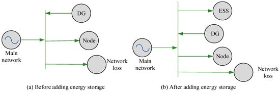
Figure 2.
Schematic diagram of power exchange between ADN and main network.
3.2. Design of ADN Network Planning Model for ESS Energy Storage Dynamic Configuration
Distribution network planning is a mathematical optimization process composed of constraint conditions and objective functions. The objective function needs to consider ecological environmental effects, safe and stable operation, economic effects of power grid operators, economic effects of value entities, new equipment access methods, etc. Constraints need to consider new energy constraints, active management measures constraints, new technology constraints, inequality or equality constraints. Distribution network planning is a complex and multi-objective planning problem with complex variables [24,25]. The planning methods used include uncertain programming, multi-stage programming, bilevel programming, multi-objective programming, and other mathematical models. This model is divided into different quarterly daily scene based on the predicted DG output and load time series during the planning period. This scenario has continuity characteristics across different quarters. The time scale of the operational and planning decision variables for energy storage is . The operational decision variable is the active power of energy storage charging and discharging in typical daily scenarios. If the value is less than 0, it indicates energy storage discharge. If the value is greater than 0, it indicates energy storage charging. The planning decision variable in the ESS configuration variable is . The construction decision quantity in ADN is . The variable is 0/1, which refers to whether or not to install the selected line between nodes and . The variable is 0/1, which refers to node not being connected or connected to ESS in the quarter. refers to the rated power of node connected to ESS in quarter . refers to the rated capacity of node to access ESS. The objective function of this model is from the perspective of the distribution network company. The cost of ESS is borne by the distribution network company. There is real-time energy exchange between the distribution network and the main network. The distribution network company determines the potential value and operation mode of ESS. It will charge fees from the electricity users of the distribution network. After ESS is added to the distribution network, the power exchange between the distribution network and the main network has subjective controllability. By effectively utilizing energy storage equipment, distribution network companies can transfer the electricity demand of users over time, shifting the electricity demand from high electricity prices and high load periods to low electricity prices and low load periods, thereby reducing the cost of purchasing electricity from the main grid. DG is invested and operated by regional energy suppliers. After ESS is added to the distribution network, the power exchange between the distribution network and the main network has subjective controllability. By effectively utilizing energy storage equipment, distribution network companies can transfer the electricity demand of users over time, shifting the electricity demand from high electricity prices and high load periods to low electricity prices and low load periods, thereby reducing the cost of purchasing electricity from the main grid. DG is invested and operated by regional energy suppliers. Under the premise of involving investment and construction by distribution network operators, the model also needs to focus on the coordinated use of energy storage equipment and maximize the comprehensive income within the planning cycle. The ADN planning process is usually accompanied by renewable energy DG. To provide a clearer analysis of the grid structure and ESS planning model, the model does not plan for DG. The capacity and location of DGs installed in the distribution network are fixed and known, and DG power generation can be predicted. The investment and operating costs are borne by the regional energy provider. The objective function of this model mainly considers the following aspects, including distribution network electricity sales revenue, distribution network electricity purchase expenditure, and cost during the planned construction period. The revenue from selling electricity in the distribution network refers to the increased revenue generated by the distribution network operator through selling electricity in the short term. The revenue from selling electricity in the distribution network refers to the short-term increase in revenue generated by the distribution network operator by selling electricity, which can be obtained through the duration of usage, user electricity consumption curve, and corresponding electricity price. The electricity price calculation method used in the study is real-time electricity price. The electricity purchase expenditure of the distribution network is calculated based on typical daily load scenarios in different seasons, and this value can be calculated through real-time power exchange, real-time electricity prices, days, and other numerical values of the transmission network. The costs during the planned construction period include construction costs, investment in grid lines, and energy storage costs. Among them, energy storage costs include mobile transportation costs, operation and maintenance costs, and energy storage investment costs. The objective function of the model can be represented by Equation (9).
In Equation (9), refers to the planning period. The electricity sales revenue and electricity purchase expenses of the distribution network in year are and , respectively. refers to the cost during the planned construction period. For the operating conditions of the distribution network, referring to the DistFlow power flow formula, a simplified DistFlow power flow equation is obtained by removing the second-order term [26,27]. The active power flowing from the starting node to the end node through line is shown in Equation (10).
In Equation (10), the power consumption of the power user at the starting node is . The operating power of the energy storage installed at the starting node is . The generation power of starting node connected to DG is . is a certain line. refers to the set of lines connected to node . is a certain node. The reactive power of the starting node flowing through line to the end node is Equation (11).
The reactive power generated by DG and the reactive power required by node electricity users are and , respectively. The constraint conditions for node voltage and branch capacity are Equation (12).
In Equation (12), the square of the voltage at node is . The minimum and maximum values of are and , respectively. The reactive power and active power in the -type line are and , respectively. The rated current carrying capacity of the -type line construction is . For network topology constraints, research is conducted to achieve line selection by adding improved spanning trees [28,29,30]. ESS operational constraints include capacity constraints and state of charge. Capacity constraints can be displayed in Equation (13).
In Equation (13), the total rated capacity and power of the added ADN energy storage device are and , respectively. refers to whether the node is connected to ESS. The minimum and maximum values of the total energy storage power with added ADN are and , respectively. The minimum and maximum total ESS capacity of adding ADN are and , respectively, which represent the limited budget for the operation of energy storage equipment and energy storage investment in the planning scheme. When considering the state of charge constraint, the energy storage battery is set to operate in a daily cycle mode. The ESS charging and discharging performance is set to simplify output. The charging and discharging time nodes are set by determining the corresponding time of peak and valley electricity prices. Figure 3 refers to a simplified diagram of the objective function and constraint conditions.

Figure 3.
Simplified diagram of objective function and constraint conditions.
The final ADN network planning model involving dynamic energy storage configuration is shown in Equation (14).
In Equation (14), the electricity price for the hour of season is . refers to the network loss power of the distribution network. refers to the operating power of the energy storage installed at the starting node . This model sets the prices for purchasing and selling electricity in the distribution network to be consistent. The DG is constructed and operated by regional energy companies, including the costs of investing in ESS and constructing lines, as well as network loss costs and energy storage profits. Figure 4 refers to the ADN network planning model involving dynamic energy storage configuration.
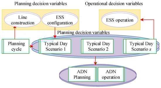
Figure 4.
ADN network planning model involving dynamic configuration of energy storage.
4. Application Effect of ADN Grid Planning Model for Dynamic Configuration of Energy Storage
To evaluate the feasibility of the ADN dynamic energy storage configuration grid joint planning scheme, three numerical examples were set up to analyze the application effect of the ADN grid planning model for energy storage dynamic configuration. The evaluation content included the results of grid planning and energy storage configuration, as well as the energy storage configuration of different example nodes in different seasons. In addition, this study also analyzed daily energy storage investment and electricity reliability from two perspectives, the distribution value of energy storage facilities and the user or energy storage facility operator.
4.1. Three Examples and Grid Planning and Energy Storage Configuration Results
To verify the performance of the ADN network planning model for dynamic energy storage configuration, a planning area with a voltage level of 10 kV, including six nodes and an area of 125 km2 was studied as an example. The load model of relevant scholars was referenced for example analysis. The planning time for the example was set to 10 years. The experiment was conducted on the MATLAB 2021 platform, using the YALMIP toolkit to write relevant programs and calling the GUROBI solver to solve the model. The computer configuration was Intel Core i5-8300H, 2.30 GHz, and 8 GB RAM.
Figure 5 referred to the planning problem of six nodes within the planning area. The horizontal coordinates of nodes one to six ranged from 178.36 to 1850.32 km. The value of the vertical axis was 169.25–586.36 km. The electricity prices for peak, valley, and flat intervals were CNY 1.1000/kWh, CNY 0.6652/kWh, and CNY 0.3346/kWh, respectively.

Figure 5.
Planning problems for 6 nodes within the planning area.
The distribution center was set to node 1. Node 2 increased the determined output of 200 kW photovoltaic power generation. Node 3 was an industrial user. Node 5 was a resident user. The other two nodes were commercial users. The four quarter load curves for different user types are shown in Figure 6. The decrease in autumn consumption by commercial consumers is compensated for by the increase in autumn consumption by residential and industrial consumers, which may be the result of the introduction of ESS. Commercial consumers share the electricity load during the peak autumn period of residential and industrial consumers.
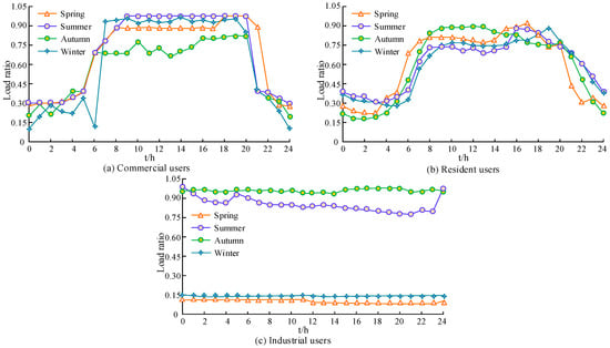
Figure 6.
Four quarterly load curves for different user types.
Table 2 was the node load and example parameters. The battery energy storage density was 200 Wh/kg. The transportation cost was CNY 20/(t·km). The value of was 0.75, and the was 100 MWh·km.
Table 2.
Node load and calculation example parameters.
Three numerical examples were analyzed to verify the performance of the model. Unrelated variables in the model were removed. Example 1 did not add ESS. Example 2 uses the same configuration in different scenarios, with ESS lower than 3. There were two types of lines: LGJ-10/2 and LGJ-35/6. The resistances of LGJ-10/2 and LGJ-35/6 were 2.706 Ω/km and 0.823 Ω/km, respectively. The reactance was 1.678 and 0.510, and the investment costs were 120,000/km and 300,000/km, respectively. The maximum current carrying capacity was 660 kVA and 1340 kVA, respectively. The difference between Example 3 and Example 2 is that EES dynamically sets EES based on different scenes in four seasons of spring, summer, autumn, and winter, while the other parameter settings are consistent with Example 2. Table 3 refers to the costs and benefits of different examples. The three calculation examples ignore the price difference between electricity purchase and sales processes, and the objective function includes network loss cost, energy storage arbitrage cost, energy storage construction cost, and grid construction cost. Example 1: During the planning period, ESS was not constructed, resulting in a lack of actual benefits and a total cost of CNY 1.0235 million. Example 1 does not involve the construction of energy storage components; therefore, the objective function has no benefits. And Example 3 obtained a net profit of CNY 212,100. Compared to Examples 1 and 2, Example 3 has lower network loss and investment costs. This indicates that energy storage can reduce the load at different seasonal peaks and the maximum flow of the line through dynamic optimal allocation of seasons, thereby reducing the investment in maximum capacity of the line.
Table 3.
Costs and benefits of different examples.
Figure 7a,b showed the grid planning and energy storage configuration results for Example 1 and Example 2, respectively. Example 1 used LGJ-35/6 between nodes 1 and 2 and nodes 2 and 3, as node 3 used a larger load compared to other nodes. The position of connection ESS in Example 2 was located at a node far away from node 1. This is because the electrical energy far from node 1 had to pass through a longer line to achieve peak charging and low peak discharge. ESS could achieve profitability. It also reduced the maximum power that branches passed through, thereby reducing the cost of grid construction.
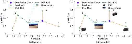
Figure 7.
Grid planning and energy storage configuration results for Example 1 and Example 2.
Figure 8a,d showed the grid planning and energy storage configuration results for the four seasons of Example 3, respectively. The location of the connection to ESS in Example 3 was also located on a node far away from node 1. The reason was the same as Example 2. Meanwhile, compared to other nodes, node 3 had a significant increase in summer load. Therefore, ESS was configured in autumn and summer. While utilizing peak valley difference arbitrage, it could also reduce the current passing between node 2 and node 3, thereby saving network construction costs.
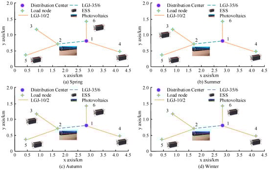
Figure 8.
Example 3: Grid planning and energy storage configuration results for four seasons.
4.2. The Results of Energy Storage Configuration at Different Nodes and the Comprehensive Effect of ESS
Table 4 showed the energy storage configuration results for each node in Example 2 and Example 3. Both Example 2 and Example 3 had three ESS configurations. This indicated that decentralized energy storage access could bring greater benefits to the distribution network compared to centralized access. In addition, the ESS access methods for Example 3 varied in different seasons. The access nodes for ESS in spring and winter were 4, 5, and 6. The access nodes for summer and autumn were 3, 5, and 6. Among them, node 5 had less energy storage capacity in spring and autumn compared to winter and summer. Node 6 had almost the same energy storage capacity throughout the year.
Table 4.
Calculation results of energy storage configuration for each node in Example 2 and Example 3.
This study analyzed the comprehensive effects of ESS from two aspects: the distribution side value of energy storage facilities and the user or energy storage facility operator. Figure 9a and Figure 9b, respectively, referred to the comparison of commercial load daily energy storage investment and electricity reliability before and after applying the DG grid planning model with ADN energy storage dynamic configuration. For the commercial daily load curve, the variation pattern of the curve before and after applying this model was the same as that of the residential daily load curve. This was because there were low and peak periods of load. When there was a peak period of power load consumption, the original line capacity and transformer capacity were difficult to supply. At this point, the upgrade and expansion should be completed as soon as possible. After applying the DG grid planning model of ADN energy storage dynamic configuration, the commercial annual power supply reliability had significantly improved, with an improvement rate of 26.31%. Therefore, ESS could provide backup power to the power system and quickly respond to power outages, minimizing the economic losses caused by power outages, especially for electricity users with special requirements such as high-tech enterprises.
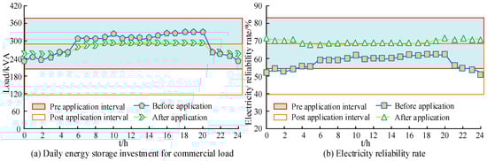
Figure 9.
Comparison of daily energy storage investment and electricity reliability of commercial load.
Figure 10a,b showed the comparison of daily energy storage investment and electricity reliability of residential load before and after applying the model. Before applying the DG grid planning model of ADN energy storage dynamic configuration, there were significant changes in the daily load curve. The maximum and minimum values were 198 kVA and 452 kVA, respectively. After applying the DG grid planning model of ADN energy storage dynamic configuration, the daily load curve was relatively smooth. The maximum and minimum values were 215 kVA and 326 kVA, respectively. After applying the DG grid planning model of ADN energy storage dynamic configuration, the reliability of residential power supply significantly improved, with an improvement rate of 23.56%. Therefore, the maximum power consumption should be considered in the planning of regional variable voltage capacity and distribution network structure.
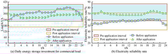
Figure 10.
Comparison of daily energy storage investment and electricity reliability of residential load.
Figure 11a,b showed the daily energy storage investment and electricity reliability of industrial loads before and after applying the DG grid planning model with ADN energy storage dynamic configuration. Similar to commercial users, after applying the DG grid planning model of ADN energy storage dynamic configuration, the daily energy storage investment for industrial loads was less, and the electricity reliability was higher. Therefore, ESS could transfer energy in time and space, making the power load curve smoother. Filling the peak period charge load with the low period charge could reduce the peak charge, maintain the normal operation of the distribution network, and delay the expansion project of the power grid.
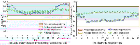
Figure 11.
Comparison of daily energy storage input and electricity reliability of industrial load.
5. Conclusions
Mobile energy storage devices have low penetration rates in the field of renewable energy utilization. At the same time, the impact of dynamic configuration of energy storage devices on grid planning under different scenarios changes. Therefore, an ADN network planning model for ESS energy storage dynamic configuration is constructed. Different numerical examples are analyzed using a planning area containing six nodes. Dynamic energy storage configuration refers to the configuration of energy in an energy storage system according to demand. During the planning period, Example 1 did not build ESS, resulting in a total cost of CNY 1.0235 million. Example 3 obtained a net profit of CNY 212,100. Compared to Examples 1 and 2, Example 3 had lower network loss and investment costs. Example 2 and Example 3 had three ESS configurations, but there were differences in access methods. Example 2 and Example 3 connected the ESS at a node far from node 1. Compared to winter and summer, node 5 had less energy storage capacity in spring and autumn. Node 6 had almost the same energy storage capacity throughout the year. Before applying the ADN grid planning model for ESS energy storage dynamic configuration, there were significant changes in the daily load curves of commercial, residential, and industrial users. After applying this model, the daily load curve was relatively stable. Before applying the ADN grid planning model for ESS energy storage dynamic configuration, the electricity reliability curves of commercial, residential, and industrial users fluctuated significantly. The reliability index of electricity consumption was improved. The distribution network framework planning method that considers dynamic energy storage configuration can reduce the network construction cost of distribution network operators, while improving the economic benefits of distribution network operators. It has potential value in the field of energy storage applications in actual distribution network power engineering. However, there are still shortcomings in the research. Subsequent research can use metaheuristic algorithms to solve the model, and load clustering methods can be used to further subdivide different scenarios. The scope of future research can be analyzed by comparing the scheduling results of modern algorithms.
Author Contributions
We designed an ADN grid planning model that considers the dynamic configuration of ESS energy storage. We analyzed the impact of optimal ESS configuration on grid planning under different load operating scenarios in summer, autumn, and winter, as well as the different site selection, capacity setting, and charging/discharging operation modes of energy storage. Based on the constraints of the spanning tree, we made improvements to achieve the selection of planned lines. Conceptualization, Y.L., P.T. and X.Y.; Data curation, Y.L.; software, Y.L.; Validation, Y.L. and X.X.; Formal analysis, Y.L. and X.X.; Resources, P.T.; Methodology, Y.L. and X.Y.; Writing—original draft, Y.L.;. Writing—review & editing, Y.L. Visualization, Y.L.; Supervision, P.T., S.C., Q.Z. and Y.Y.; Project administration, P.T., X.X. and S.C.; Funding acquisition, P.T., Q.Z. and Y.Y. All authors have read and agreed to the published version of the manuscript.
Funding
State Grid Company Limited Headquarters Management Technology Project (5108-202218280A-2-376-XG).
Data Availability Statement
The data provided in this study is not available for privacy reasons.
Conflicts of Interest
Qi Zhou, Yi Yang were employed by Electric Power Science Research Institute of State Grid Jiangsu Electric Power Company. The remaining authors declare that the research was conducted in the absence of any commercial or financial relationships that could be construed as a potential conflict of interest.
Abbreviations
| ADN | Active Distribution Network | Annual growth rate of load | |
| DG | Distributed Generation | The ratio of rated energy storage power to peak load power | |
| ESS | Energy Storage System | Annual reduction in power distribution network losses | |
| Rated power of energy storage for node in the quarter | The number of days in the season | ||
| Rated Energy Storage Capacity for Node in the quarter | Number of system bus routes | ||
| Income from deferred construction | Distribution network lines | ||
| Delayed total investment | Line resistance | ||
| Inflation rate | The square of the current before the line is connected to the energy storage system | ||
| Internal rate of return | The square of the current after the line is connected to energy storage | ||
| Delaying investment period | Network loss benefits of peak and valley electricity prices | ||
| Electricity price for the hour | Charging power for node installation energy storage | ||
| Grid connected backup effect | Total number of nodes in the system | ||
| Reserve capacity price | The total energy storage capacity connected to the energy storage device | ||
| Reserve value consumed for energy storage equipment replacement | The total power of energy storage connected to the energy storage device | ||
| Demand side response profit | Recovery coefficient | ||
| ESS unit power investment cost | The time scale of operational and planning decision variables | ||
| Unit rated capacity | Active power of energy storage charging and discharging in typical daily scenarios | ||
| ESS unit power operation and maintenance cost | ESS configuration variables | ||
| Annual operation and maintenance cost of unit energy storage rated power | Construction decision volume | ||
| Planning period | Power consumption of power users at starting node | ||
| Revenue from sales of electricity in the distribution network in the year | The operating power of the energy storage installed at starting node | ||
| Electricity purchase expenses for distribution network in the year | The power generation of starting node connected to DG | ||
| Active power flowing from starting node to end node through line | A certain route | ||
| Collection of lines connected to node | Reactive power generated by DG | ||
| A certain node | Node reactive power required by electricity users | ||
| Reactive power flowing from starting node to end node through line | The voltage square of node | ||
| The rated current carrying capacity of the type of line construction | |||
| The total rated capacity of ADN energy storage devices | |||
| Reactive power in the type of line | The total rated power of ADN energy storage devices | ||
| Active power in the type of line | Is the node connected to ESS | ||
| Minimum value of total energy storage power with added ADN | Minimum total ESS capacity for adding ADN | ||
| Maximum value of total energy storage power with added ADN | Maximum total ESS capacity for adding ADN | ||
| Electricity price for the hour of the season | The operating power of the energy storage installed at starting node | ||
| Network loss power of distribution network | - | - |
References
- Awadallah, M.A.; Venkatesh, B. Energy storage in distribution system planning and operation: Current status and outstanding challenges. Can. J. Electr. Comput. Eng. 2019, 41, 10–19. [Google Scholar] [CrossRef]
- Abdeltawab, H.; Mohamed, Y.A.-R.I. Mobile Energy storage sizing and allocation for multi-services in power distribution systems. IEEE Access 2019, 7, 176613–176623. [Google Scholar] [CrossRef]
- Li, Z.; Su, S.; Zhao, Y.; Jin, X.; Chen, H.; Li, Y.; Zhang, R. Energy management strategy of active distribution network with integrated distributed wind power and smart buildings. IET Renew. Power Gener. 2020, 14, 2255–2267. [Google Scholar] [CrossRef]
- Huang, Z.; Fang, B.; Deng, J. Multi-objective optimization strategy for distribution network considering V2G-enabled electric vehicles in building integrated energy system. Prot. Control. Mod. Power Syst. 2020, 5, 7. [Google Scholar] [CrossRef]
- Li, Z.; Su, S.; Jin, X.; Chen, H. Distributed energy management for active distribution network considering aggregated office buildings. Int. J. Renew. Energy 2021, 180, 1073–1087. [Google Scholar] [CrossRef]
- Liang, X.; Saaklayen, A.; Igder, M.A.; Shawon, S.M.R.H.; Faried, S.O.; Janbakhsh, M. Planning and service restoration through microgrid formation and soft open points for distribution network modernization: A review. IEEE Trans. Ind. Appl. 2022, 58, 1843–1857. [Google Scholar] [CrossRef]
- Huang, C.; Wang, C.; Xie, N.; Wang, Y. Robust coordination expansion planning for active distribution network in deregulated retail power market. IEEE Trans. Smart Grid 2019, 11, 1476–1488. [Google Scholar] [CrossRef]
- Zhang, Y.; Xu, Y.; Yang, H.; Dong, Z.Y. Voltage regulation-oriented co-planning of distributed generation and battery storage in active distribution networks. Int. J. Electr. Power Energy Syst. 2019, 105, 79–88. [Google Scholar] [CrossRef]
- Gao, H.; Wang, R.; Liu, Y.; Wang, L.; Xiang, Y.; Liu, J. Data-driven distributionally robust joint planning of distributed energy resources in active distribution network. IET Gener. Transm. Distrib. 2020, 14, 1653–1662. [Google Scholar] [CrossRef]
- Yan, X.; Li, R. Flexible coordination optimization scheduling of active distribution network with smart load. IEEE Access 2020, 8, 59145–59157. [Google Scholar] [CrossRef]
- Wenzhi, S.; Zhang, H.; Tseng, M.-L.; Weipeng, Z.; Xinyang, L. Hierarchical energy optimization management of active distribution network with multi-microgrid system. J. Ind. Prod. Eng. 2022, 39, 210–229. [Google Scholar] [CrossRef]
- Venkateswaran, V.B.; Saini, D.K.; Sharma, M. Approaches for optimal planning of the energy storage units in distribution network and their impacts on system resiliency. CSEE J. Power Energy. 2020, 6, 816–833. [Google Scholar] [CrossRef]
- Xie, S.; Hu, Z.; Wang, J.; Chen, Y. The optimal planning of smart multi-energy systems incorporating transportation, natural gas and active distribution networks. Appl. Energy 2020, 269, 115006–115040. [Google Scholar] [CrossRef]
- Valencia, A.; Hincapie, R.A.; Gallego, R.A. Optimal location, selection, and operation of battery energy storage systems and renewable distributed generation in medium–low voltage distribution networks. J. Energy Storage 2020, 34, 102158.1–102158.16. [Google Scholar] [CrossRef]
- Santos, S.F.; Gough, M.; Fitiwi, D.Z.; Pogeira, J.; Shafie-Khah, M.; Catalão, J.P.S. Dynamic distribution system reconfiguration considering distributed renewable energy sources and energy storage systems. IEEE Syst. J. 2022, 16, 3723–3733. [Google Scholar] [CrossRef]
- Esmaeeli, M.; Kazemi, A.; Shayanfar, H.; Chicco, G.; Siano, P. Risk-based planning of the distribution network structure considering uncertainties in demand and cost of energy. Energy 2022, 119, 578–587. [Google Scholar] [CrossRef]
- Wang, D.; Ding, H. Research on Double Layer Coordinated Optimization Planning of Distribution Network with Distributed Generation. In Proceedings of the 2023 3rd International Conference on Energy Engineering and Power Systems (EEPS), IEEE, Dali, China, 28–30 July 2023; Volume 6, pp. 924–927. [Google Scholar]
- Gu, H.; Yu, J.; Shen, Y.; Li, Y.; Guan, D.; Ye, P. Bi-Level Decentralized Optimal Economic Dispatch for Urban Regional Integrated Energy System under Carbon Emission Constraints. IEEE Access 2022, 10, 62341–62364. [Google Scholar] [CrossRef]
- Cheng, Y.; Zhang, N.; Zhang, B.; Kang, C.; Xi, W.; Feng, M. Low-Carbon Operation of multiple energy systems based on energy-carbon integrated prices. IEEE Trans. Smart Grid 2019, 11, 1307–1318. [Google Scholar] [CrossRef]
- Jiang, X.; Chen, J.; Wu, Q.; Zhang, W.; Zhang, Y.; Liu, J. Two-step optimal allocation of stationary and mobile energy storage systems in resilient distribution networks. J. Mod. Power Syst. Clean 2021, 9, 788–799. [Google Scholar] [CrossRef]
- Liu, X.; Liu, X.; Jiang, Y.; Zhang, T.; Hao, B. Photovoltaics and Energy Storage Integrated Flexible Direct Current Distribution Systems of Buildings: Definition, Technology Review, and Application. CSEE J. Power Energy Syst. 2023, 9, 829–845. [Google Scholar] [CrossRef]
- Wang, B.; Zhang, C.; Dong, Z.Y.; Li, X. Improving hosting capacity of unbalanced distribution networks via robust allocation of battery energy storage systems. IEEE Trans. Power Syst. 2020, 36, 2174–2185. [Google Scholar] [CrossRef]
- Jiang, X.; Chen, J.; Chen, M.; Wei, Z. Multi-stage dynamic post-disaster recovery strategy for distribution network considering integrated energy and transportation network. CSEE J. Power Energy Syst. 2020, 7, 408–420. [Google Scholar] [CrossRef]
- Yu, P.; Wan, C.; Song, Y.; Jiang, Y. Distributed control of multi-energy storage systems for voltage regulation in distribution networks: A back-and-forth communication framework. IEEE Trans. Smart Grid 2020, 12, 1964–1977. [Google Scholar] [CrossRef]
- Zhao, L.; Huang, Y.; Dai, Q.; Yang, L.; Chen, F.; Wang, L.; Sun, K.; Huang, J.; Lin, Z. Multistage active distribution network planning with restricted operation scenario selection. IEEE Access 2019, 7, 121067–121080. [Google Scholar] [CrossRef]
- Usman, A.M.; Abdullah, M.K. An Assessment of Building Energy Consumption Characteristics Using Analytical Energy and Carbon Footprint Assessment Model. Green Low-Carbon Econ. 2023, 1, 28–40. [Google Scholar] [CrossRef]
- Cao, X.; Cao, T.; Gao, F.; Guan, X. Risk-averse storage planning for improving res hosting capacity under uncertain siting choices. IEEE Trans. Sustain. Energy 2021, 12, 1984–1995. [Google Scholar] [CrossRef]
- Zhong, W.; Xie, S.; Xie, K.; Yang, Q.; Xie, L. Cooperative P2P energy trading in active distribution networks: An milp-based nash bargaining solution. IEEE Trans. Smart Grid 2020, 12, 1264–1276. [Google Scholar] [CrossRef]
- Luo, Y.; Nie, Q.; Yang, D.; Zhou, B. Robust optimal operation of active distribution network based on minimum confidence interval of distributed energy beta distribution. J. Mod. Power Syst. Clean 2020, 9, 423–430. [Google Scholar] [CrossRef]
- Somakumar, R.; Kasinathan, P.; Monicka, G.; Rajagopalan, A.; Ramachandaramurthy, V.K.; Subramaniam, U. Optimization of emission cost and economic analysis for microgrid by considering a metaheuristic algorithm-assisted dispatch model. Int. J. Numer. Model. Electron. 2022, 35, e2993. [Google Scholar] [CrossRef]
Disclaimer/Publisher’s Note: The statements, opinions and data contained in all publications are solely those of the individual author(s) and contributor(s) and not of MDPI and/or the editor(s). MDPI and/or the editor(s) disclaim responsibility for any injury to people or property resulting from any ideas, methods, instructions or products referred to in the content. |
© 2023 by the authors. Licensee MDPI, Basel, Switzerland. This article is an open access article distributed under the terms and conditions of the Creative Commons Attribution (CC BY) license (https://creativecommons.org/licenses/by/4.0/).