Article

Intensification of Hydrogen Production: Pd–Ag Membrane on Tailored Hastelloy-X Filter for Membrane-Assisted Steam Methane Reforming

by
Serena Agnolin
1,
Luca Di Felice
1,
Alfredo Pacheco Tanaka
1,2,
Margot Llosa Tanco
1,2,
Wout J. R. Ververs
1 and
Fausto Gallucci
1,3,*
1
Inorganic Membranes and Membrane Reactors, Sustainable Process Engineering, Department of Chemical Engineering and Chemistry, Eindhoven University of Technology, De Rondom 70, 5612 AP Eindhoven, The Netherlands
2
TECNALIA, Basque Research and Technology Alliance (BRTA), Mikeletegi Pasealekua 2, 20009 Donostia-San Sebastian, Spain
3
Eindhoven Institute for Renewable Energy Systems (EIRES), Eindhoven University of Technology, P.O. Box 513, 5600 MB Eindhoven, The Netherlands
*
Author to whom correspondence should be addressed.
Processes 2024, 12(1), 40; https://doi.org/10.3390/pr12010040
Submission received: 13 November 2023 / Revised: 9 December 2023 / Accepted: 20 December 2023 / Published: 22 December 2023

Abstract

:
H2 production via membrane-assisted steam methane reforming (MA-SMR) can ensure higher energy efficiency and lower emissions compared to conventional reforming processes (SMR). Ceramic-supported Pd–Ag membranes have been extensively investigated for membrane-assisted steam methane reforming applications, with outstanding performance. However, costs, sealings for integration in the reactor structure, and resistance to solicitations remain challenging issues. In this work, the surface quality of a low-cost, porous Hastelloy-X filter is improved by asymmetric filling with α-Al2O3 of decreasing size and deposition of γ-Al2O3 as an interdiffusion barrier. On the modified support, a thin Pd–Ag layer was deposited via electroless plating (ELP), resulting in a membrane with H2/N2 selectivity >10,000. The permeation characteristics of the membrane were studied, followed by testing for membrane-assisted methane steam reforming. The results showed the ability of the membrane reactor to overcome thermodynamic conversion of the conventional process for all explored operating conditions, as well as ensuring 99.3% H2 purity in the permeate stream at 500 °C and 4 bar.

1. Introduction

Methane steam reforming (SMR) is a fundamental chemical process widely employed to produce hydrogen (H2) and synthesis gas (syngas), which are essential feedstocks in various industrial applications, including ammonia production, petrochemical processes, and clean energy technologies such as fuel cells [1]. The SMR process is endothermic, requiring high temperatures and substantial energy input, often achieved through the combustion of fossil fuels, which results in significant greenhouse gas emissions.
Hydrogen production via SMR is summarized by Equation (1), and it involves two main contributions. Methane reacts with steam to form H2 and CO (Equation (2)), which is also converted into CO2 and more H2 with a water–gas-shift reaction (Equation (3)). Currently, SMR is a consolidated process performed in a reformer reactor at high temperatures (800–900 °C) and 14–20 bar, followed by two water–gas-shift reactors and hydrogen separation and purification steps (i.e., PSA, cryogenic separation) [2,3].
C H 4 + 2 H 2 O = C O 2 + 4 H 2 , H 0 = 165   k J / m o l
C H 4 + H 2 O = C O + 3 H 2 , H 0 = 206   k J / m o l
C O + H 2 O = C O 2 + H 2 , H 0 = 41   k J / m o l
To address the environmental and energy efficiency challenges associated with conventional SMR, membrane reactors have emerged as a promising approach. In the context of SMR, membrane reactors hold the potential to mitigate the environmental impact of hydrogen and syngas production while enabling efficient resource utilization [4,5,6]. Membrane reactors combine catalysis and selective permeation within a single unit, allowing for simultaneous reaction and hydrogen separation by a selective membrane. In this way, the shift reactors, PSA, or cryogenic distillation units are avoided, enhancing conversion rates, reducing energy consumption, and potentially achieving high-purity product streams. For these reasons, membrane-assisted steam methane reforming (MA-SMR) was widely investigated in the literature both in fixed-bed and fluidized-bed conditions [6,7,8,9,10,11,12].
The potential of the technology favored the investigation of possible membrane candidates, such as ceramic-based membranes (i.e., silica [13,14], silica supported on γ-Al2O3 [15]) and dense metal membranes, both self-standing and supported. Among them, Pd-based membranes are the most suitable candidates for a membrane reactor for steam reforming due to their extensively discussed perm-selectivity to hydrogen [16,17]. Ceramic-supported Pd-based membranes are the most widely investigated for this type of application, yielding outstanding hydrogen purity, especially if equipped with additional ceramic protective layers [18,19,20]. However, the drawbacks related to reactor integration and gas tightness of their sealings remain challenges to overcome, making the investigation of metallic-supported membranes an interest for this application [21,22]. Porous metal filters that are able to withstand long high-temperature exposures and with controlled surface characteristics (which can mimic their deposition-ready ceramic counterparts) are scarce on the market at competitive prices for industrial scale-ups. For this reason, it is necessary to acquire cheaper options, which result in less surface quality and, thus, in membranes with larger defects. It is, therefore, imperative to develop suitable pre-treatments to bring these unrefined, large media-grade filters to sufficient surface quality for Pd–Ag deposition [23,24,25,26,27,28,29,30,31,32,33,34].
Given the aforementioned considerations, we propose a feasibility study of the integration of a newly developed Pd–Ag membrane supported on a cheap Hastelloy-X filter in an SMR reactor.
In this work, we propose the conditioning of a Hastelloy-X filter with a 0.5 µm media grade and 4.32 µm surface roughness to support a 6–8 µm thick Pd–Ag membrane without defects. The filter was treated via polishing, chemical etching, and asymmetrically filled with α-Al2O3 of decreasing size, reproducing the procedure followed in our previous work on ammonia decomposition applications [35]. The fabrication procedure focused on the reproduction of the pore size distribution of the asymmetrically filled support of our previously tested membrane. Specifically, reproduction by the target method (with the target being the pore size distribution) is characterized via capillary flow porometry (CFP) and surface morphology evolution analysis (via laser-optical confocal microscopy), filling the new support until the desired pore size distribution target is reached. The support was equipped with a γ-Al2O3 interdiffusion barrier to prevent Pd-support interdiffusion (chosen amongst several ceramic barriers developed in previous literature [17,36,37,38,39,40,41,42,43,44,45,46,47,48,49,50,51]), and the membrane was completed with the Pd–Ag layer via ELP. Subsequently, the permeation properties of the membrane were studied in ideal permeation conditions (H2 and N2) and CO/H2-mixture permeation conditions. Finally, the methane steam reforming reaction was performed in a fixed-bed membrane reactor at different temperatures and pressures, providing insightful information on the behavior of these newly developed membranes during short-term operation.

2. Materials and Methods

2.1. Support and Membrane Preparation

A commercial unrefined porous Hastelloy-X filter with an outer diameter of 1.2 cm, average surface roughness (Ra) of 4.32 µm, and 0.5 µm nominal media grade (MG) was acquired from Hebei Golden Flame Wire Mesh Co., Hengshui, China. The filter was cut into three pieces of 10 cm length each and welded to dense stainless steel (AISI316L) tubes to achieve a dead-end configuration. The rough filters were then polished in an industrial surface finishing machine (ERBA EVT-170, Erba Makina, Istanbul, Turkey) via a wet-polishing mechanism for 6 h to reduce the roughness profile peaks. The polished filters were then chemically etched in Aqua Regia via vertical immersion for 30 s to recover the superficial porosity that was lost during polishing. After the mordant attack, the filters were thoroughly rinsed with deionized water to remove all residuals and avoid the continuation of the etching process. Oxidation in a static air atmosphere was then performed in a furnace for 1 h at 750 °C, with a heating/cooling rate of 2 °C/min.
The filters’ superficial pore sizes were reduced via asymmetrical filler coating, developed in our previous work [24]. The fillers were embedded in the filter’s superficial pores via vacuum-assisted dip-coating for 60 s per immersion cycle. Between each cycle, the filter surface was gently rinsed with distilled water. The selected fillers were spherical particles of α-Al2O3 from Sumitomo of 18, 5, and 1.5 μm diameter. The particles (10 wt.%) were dispersed in water with a magnetic stirrer, while 67% HNO3 (Sigma-Aldrich, St. Louis, MO, USA) was added dropwise to protonate the particles‘ surfaces and improve the stability of the suspension.
In order to reproduce the highly selective membrane M1, which was tested for ammonia decomposition in our previous work [35], the superficial pore diameter distribution peak (~100 nm) of the M1′s filled support was set as the target. M2 was then reproduced by filling the support up until the target was reached. To achieve overlapping distributions, 30 coating cycles were performed with alumina 18 µm (AA-18, Sumitomo, Tokyo, Japan), 20 coating cycles with alumina 5 µm (AA-5, Sumitomo), and 10 with alumina 1.5 µm (AA-1, Sumitomo). For comparison purposes, S2 was filled using the same procedure (Table 1).
A mesoporous ceramic barrier was deposited onto M2 via dip-coating and sintering to prevent the strong interaction between the Pd and the metallic support [36,37,38,39,40,41,42,43] and to complete the improvement in the support’s surface roughness. For comparison purposes, this layer was deposited on a support (S3) without alumina fillings (Table 1). The treated supports were dipped in a solution containing 0.9 wt.% boehmite loading, 3.5 wt.% polyvinyl alcohol (PVA) (MW 130000, Sigma Aldrich), and 1 wt.% polyethylene glycol (PEG) (MW 400, Sigma Aldrich). The deposited layer was dried under rotation in a climate chamber at 40 °C and 60% relative humidity for 1 h and sintered for 1 h at 550 °C in a static air furnace, with a heating/cooling rate of 2 °C/min.
Onto M2 and S3 (both equipped with γ-Al2O3) Pd–Ag films were deposited via simultaneous electroless plating (SELP), developed by Llosa-Tanco and Pacheco-Tanaka [52] and used in our previous works [24,35]. For each membrane, two ELP processes were carried out, reaching a total Pd–Ag thickness of 6–8 µm. The membranes were annealed at 550 °C for 4 h under H2/Ar atmosphere. To avoid embrittlement, Solely Ar was employed under 300 °C. The complete M2 membrane is shown in Figure 1; both ends are welded to dense stainless steel tubes, one closed cap, and one open-end tube to allow the passage of H2. M2 was employed for the SMR studies.

2.2. Characterization

The membrane preparation procedure was characterized by the following techniques:
  • The surface roughness of the untreated and pre-treated filters was measured via contact profilometry (MarSurf PS 10, Mahr Gmbh, Esslingen, Germany). The media grade and elemental composition were provided by the supplier.
  • The N2 permeance of untreated and pre-treated filters was measured in a gas permeation setup, which is described in our previous work [23].
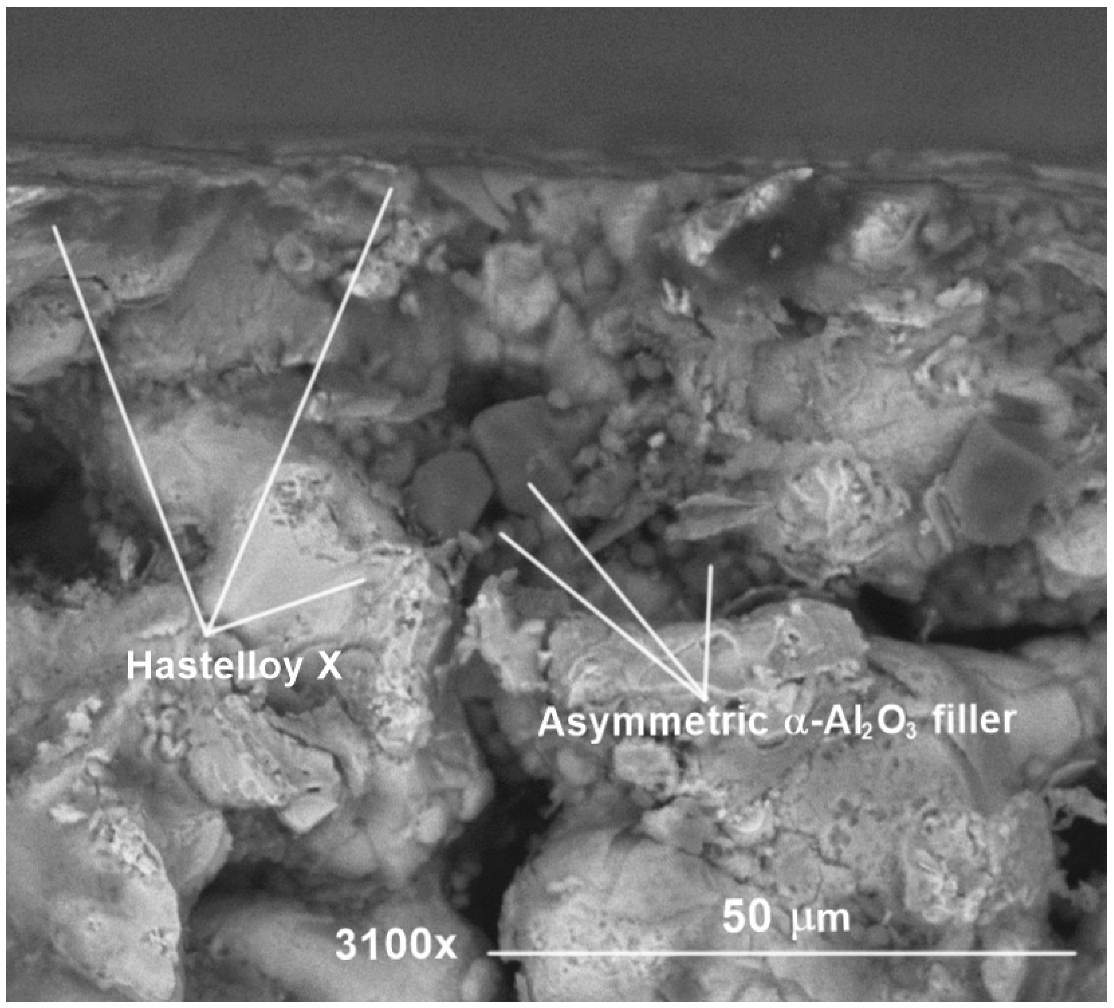
  • The presence of α-Al2O3 filler particles embedded in the treated filter was studied via scanning electron microscopy (SEM, Phenom Pro, ThermoFisher, Waltham, MA, USA) of a twin-filled filter’s cross-section (S2). To preserve the metallographic structure of the porous metal, the samples were prepared via scoring and breakage of the tube and observed as is.
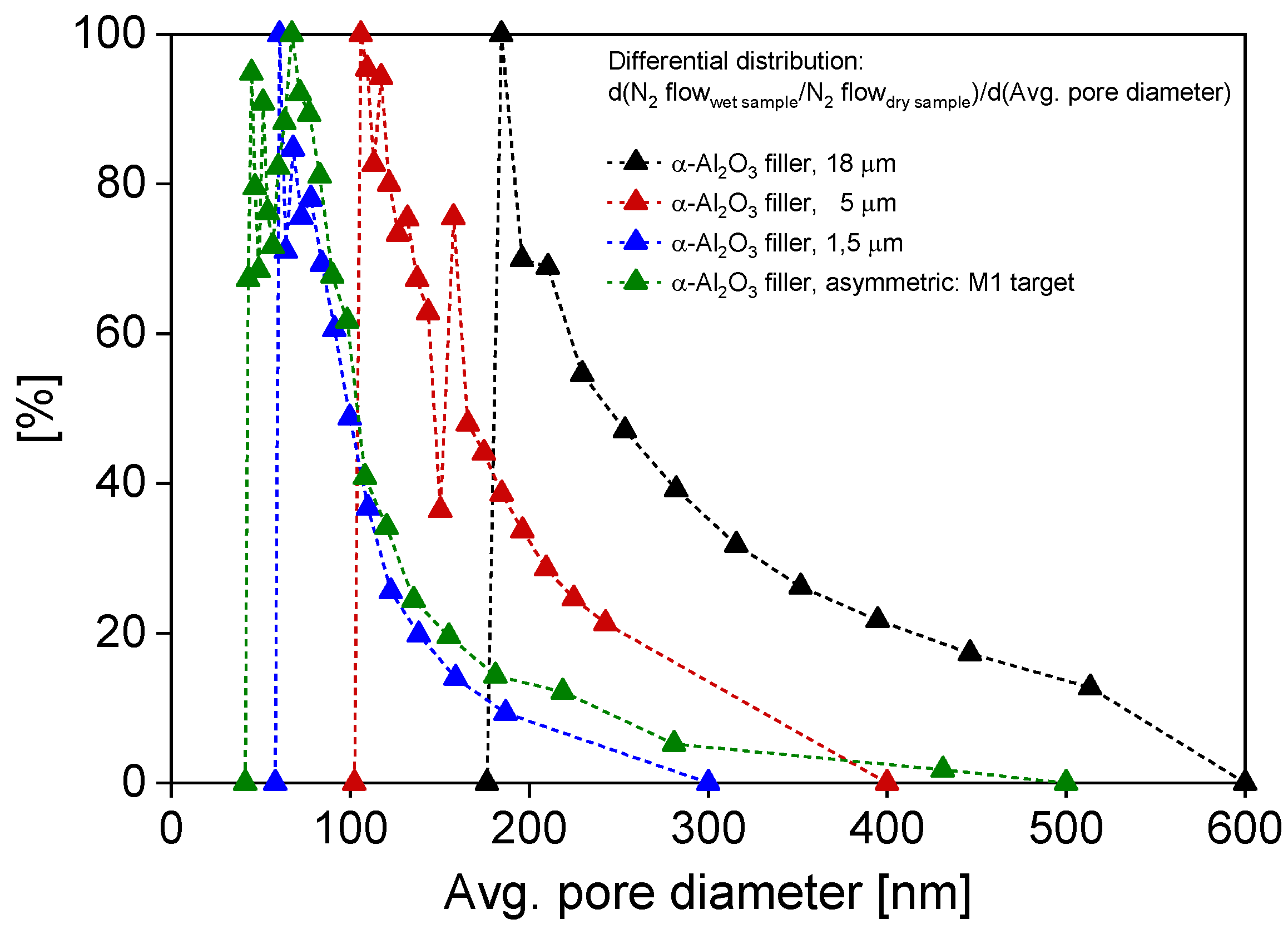
  • The pore size distribution evolution of M2’s support during the reproduction procedure was measured via capillary flow porometry (CFP) [53] in a specifically designed setup described in our previous work [24] (See Supplementary Materials).
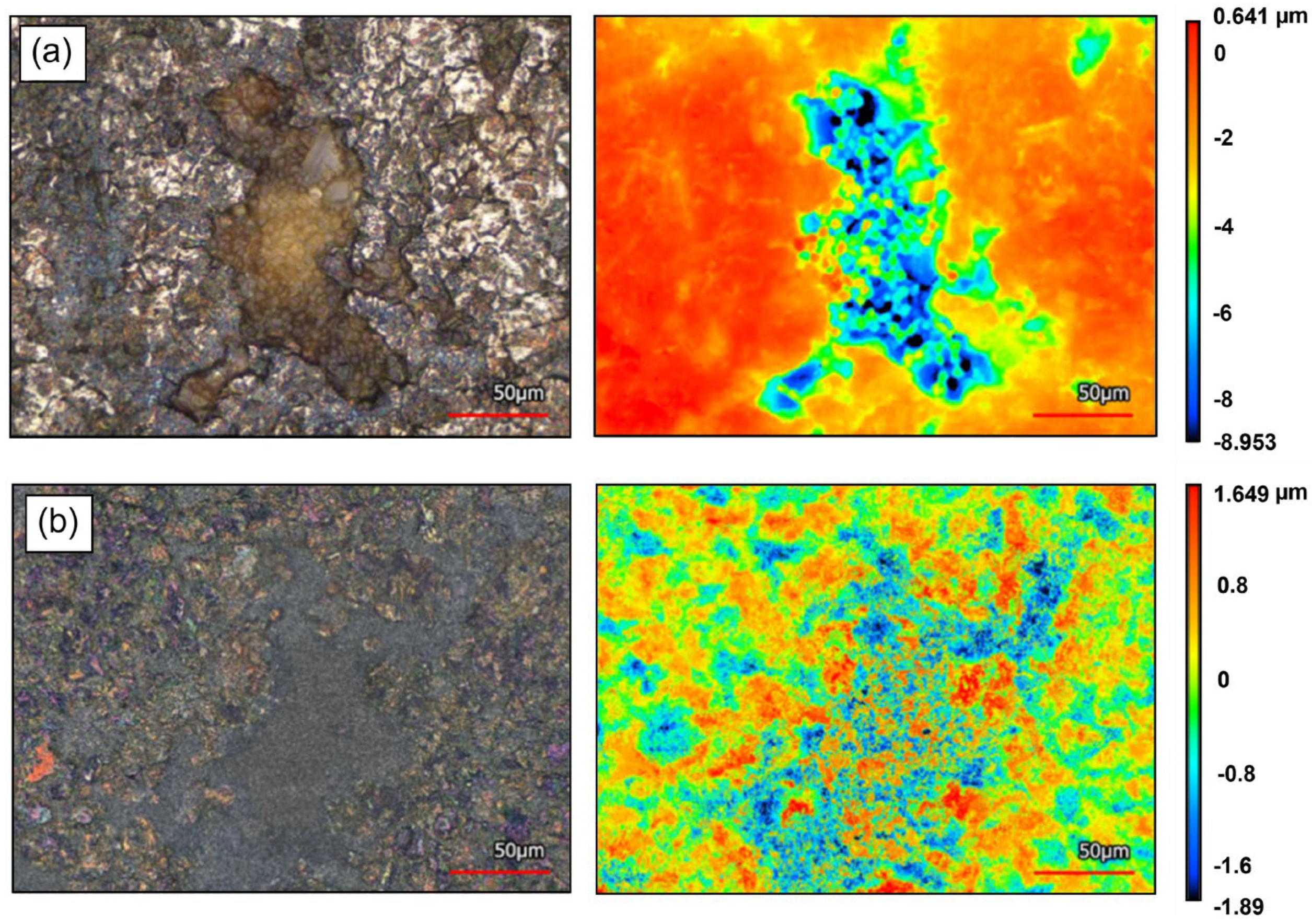
  • The superficial morphology of M2’s support filter was observed via optical-laser confocal microscopy (VKX-3000, Keyence, Osaka, Japan), both before and after interdiffusion layer deposition.
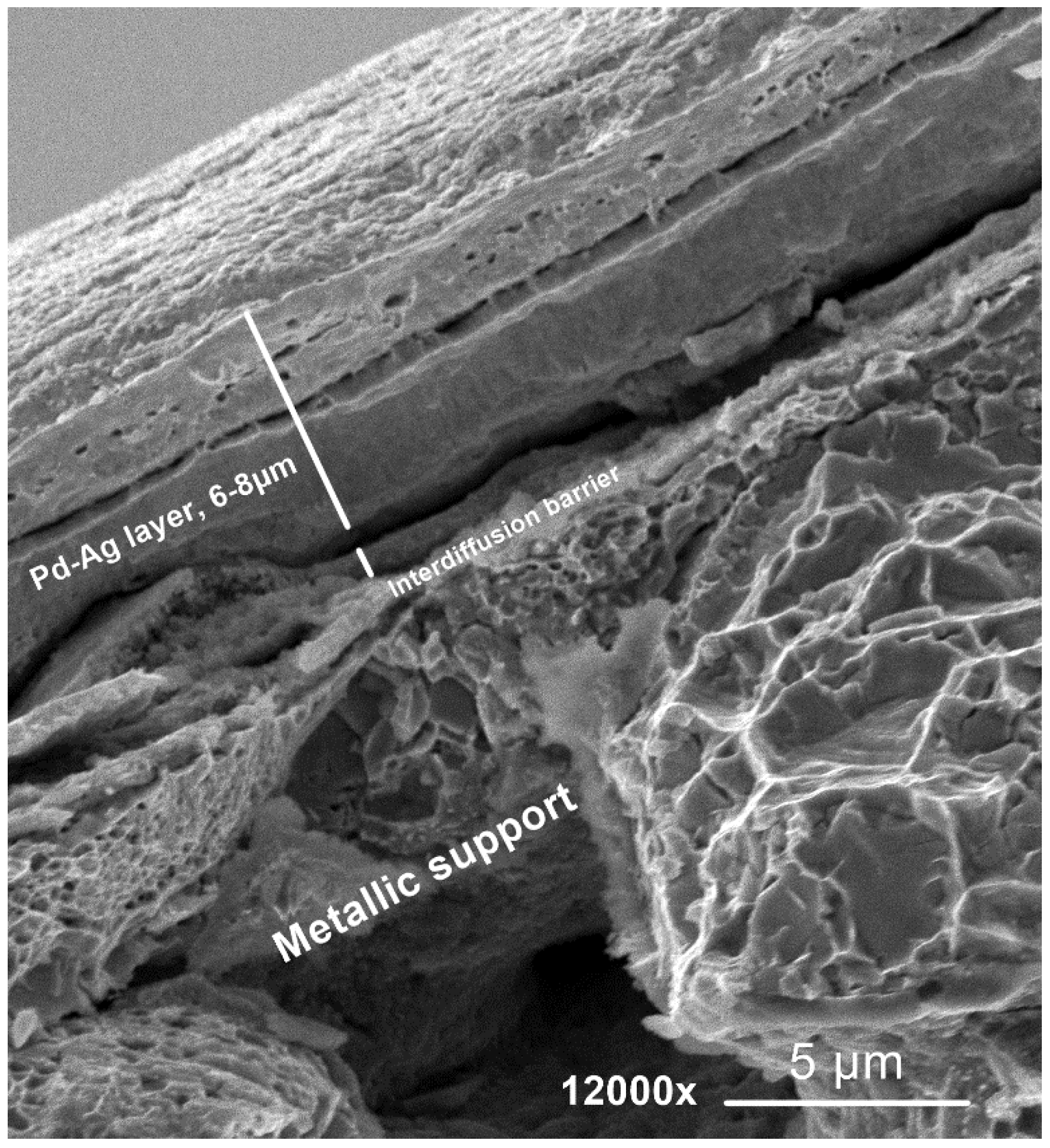
  • The thickness of the Pd–Ag layer was measured on S3 via SEM imaging with the SEM, Fei-Quanta- FEG250- 3D (FEI Company, Hillsboro, Oregon, USA).

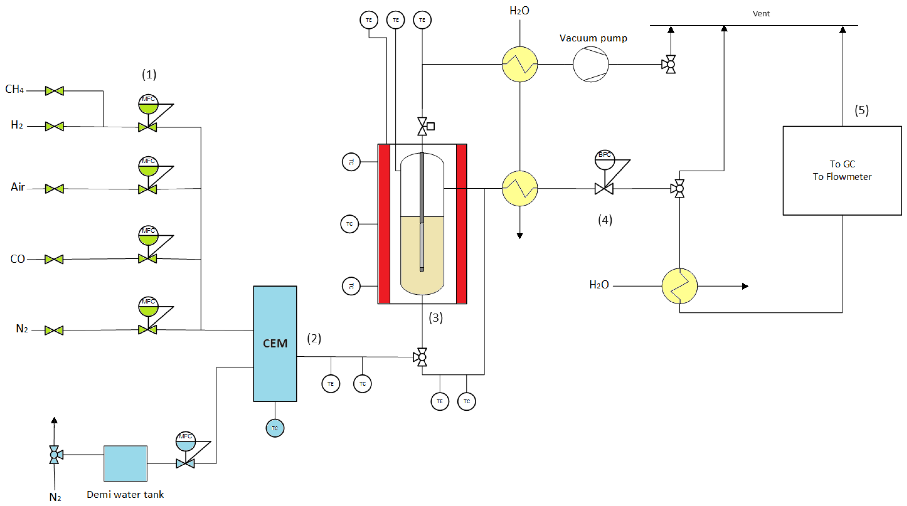
2.3. Experimental Setup for Permeation and Methane Steam Reforming

Methane steam reforming tests were performed in a stainless steel tubular membrane reactor (Internal diameter = 4.5 cm, length = 28 cm) with the Pd–Ag membrane M2 immersed in a packed bed of catalyst (300 g, commercial 2 wt.% Rh/Al2O3, 1 mm spheres, Jonson Matthey, London, United Kingdom). The reactor temperature was controlled by an external oven via three thermocouples placed at different reactor heights. The reaction temperature was monitored via three thermocouples inside the reactor. The reactor was equipped with a porous stainless steel gas distributor to ensure uniform reactant gas feeding. The feedstock gases (CH4 and N2) were fed via mass flow controllers (Bronkhorst, Ruurlo, The Netherlands), while steam was fed through a controlled evaporation system (Bronkhorst). Note that N2 is fed solely to verify the correctness of the experimental mass balance.
The reaction products were rid of steam via downstream water coolers both at the retentate and permeate side, and the gases were sent to a microGC (Interscience, CompactGC 4.0, 3 channels, Saint Nom, France) for analysis. Moreover, the permeate and retentate streams flowed through a bubble flowmeter (Horiba Stec VP3/VP1, Yongin City, Republic of Korea) to fully characterize the outlet flow rates. The permeate stream tube was closed to perform standard SMR experiments, opened to have the permeate stream at atmospheric pressure, or connected to a vacuum pump for H2 to increase the permeating flow if necessary. The reaction pressure was controlled via a backpressure regulator (Bronkhorst) at the retentate side. A schematic representation of the setup is given in Figure 2.

2.4. Experimental Methods

Before the integration in the reactor, membrane M2 was sealed with graphite tape, pressed into a 1.3 cm stainless steel ring, and tested by introducing helium at 1 bar by the bore of the membrane and bubbling in ethanol to detect any possible leakages. As no leakages were observed, the membrane was connected to the reactor flange via Swagelok fittings. The reactor was heated to 500 °C under a N2 flow with a 2 °C/min heating ramp. The membrane was then activated in a H2 flow of 1 L/min until stable permeation. Subsequently, single-gas (H2 and N2) and binary-mixture (CO/H2) gas permeation tests were performed.
The reactor was cooled down at a 1 °C/min rate, and the M2 was subsequently submerged in the catalyst bed. Heating and activation were performed once again, reaching 400 °C. The procedure then followed with permeation tests in reactive conditions. During SMR operation, a vacuum was applied to the permeate side to maximize H2 permeance. The explored operating conditions are summarized in Table 2.
The single-gas permeation tests were performed at three different temperatures (400, 450, 500 °C) and pressures (1, 2, 3 barg) to retrieve the characteristic membrane activation energy (Ea). Moreover, pure H2 permeance and ideal H2/N2 selectivity were fully characterized.
Following the ideal conditions, CO/H2-mixture tests were performed to assess the effect of CO on the H2 permeance of the membrane. Specifically, the explored concentrations of CO ranged between 5 and 15% since a highly selective membrane would not allow >15% of CO to permeate through. For each explored concentration, the hydrogen permeation flux was evaluated at 400, 450, and 500 °C and 2, 3, and 4 bar at the retentate side.
Methane steam reforming tests were performed at 400, 450, and 500 °C to study realistic membrane operation temperatures. For each temperature, a conventional methane steam reforming reaction was carried out at the reference pressure of 4 bar retentate side by closing the permeate stream. Once the reference case was assessed, the permeate stream was restored, and the MA-SMR was performed in the specified pressure range (Table 2). For all cases, the reaction performance was monitored until steady operation. The composition and flow rates of both permeate and retentate streams were measured 5 times, as well as both outlet flow rates. The CH4 conversion was calculated as the consumed methane over the total methane inlet (Equation (4)); the H2 recovery factor (HRF) was calculated as the permeated hydrogen over the maximum amount of hydrogen producible at full conversion (Equation (5)), the hydrogen separation factor (SF) was calculated as the permeating hydrogen over the total hydrogen produced by the current reaction (Equation (6)), and the hydrogen purity (HP) was calculated as the percentage of H2 detected in the permeate stream.
X C H 4 = C H 4 , i n C H 4 , o u t C H 4 , i n
H 2 , r e c o v e r y = H 2 , p e r m 3 · C H 4 , i n
H 2 , s e p a r a t i o n = H 2 , p e r m H 2 , p r o d

3. Results and Discussion

3.1. Support and Membrane Preparation

To obtain defect-free supported Pd–Ag membranes, the surface of the support should be smooth. However, the surface of the acquired porous Hastelloy filters presented a large average surface roughness (Ra). Therefore, before the tailored support filling procedure, the Hastelloy filter, M2, was polished, reducing its initial surface roughness (Ra) from 4.32 µm to 0.9 µm. The loss in superficial porosity due to the polishing procedure was then recovered via chemical etching, increasing the Ra to 1.2 µm but promoting an increase in the N2 permeance from ~1 × 10⁻⁵ mol/m2/s/Pa to ~5 × 10⁻⁵ mol/m2/s/Pa (at 1 barg trans-sample pressure). Following these physico-chemical pre-treatments, the α-Al2O3 filler was introduced into the large superficial openings.
In Figure 3, the surface morphology of a superficial pore mouth on the M2 support after filling and interdiffusion barrier deposition is shown in optical-laser view and height distribution. In Figure 3a, the presence of the asymmetrical filling configuration is clearly distinguishable, with filler of lower dimension (5 and 1.5 µm) laying onto larger alumina particles (18 µm), clogging a pore of the metallic filter. In the height distribution view (right), the highest and lowest points of the surface can be observed in red and blue, respectively. The filler particles can be observed in green, while the presence of blue zones indicates that the large pore structure has been reduced into relatively smaller (<50 μm) scattered pores.
In Figure 3b, the leveling effect and the further reductions in the sizes of superficial openings, thanks to the γ-Al2O3 interdiffusion barrier deposition, are clearly observable in the laser-optical view images. In the height imaging view, a reduction in the diameter of blue zones (lowest height points corresponding to superficial openings) can be observed. Furthermore, the height distribution is more symmetrically centered around 0 (green) with respect to Figure 3a, indicating a more uniform surface.
The presence of alumina filler in the support structure is further confirmed in Figure 4 by examination of a twin support cross-section (S2). The SEM imaging shows a clear presence of larger and smaller alumina particles inside a cross-sectional pore structure surrounded by Hastelloy-X alloy. The SEM examination of the twin support’s cross-section further confirms the presence of the filler not only onto the superficial pore openings but also well inside the pore necks, guaranteeing a reduction in the average pore diameter and thus avoiding the collapse of the palladium film inside the pore during electroless plating deposition.
In Figure 5, the pore size distribution evolution after successive fillings with α-Al2O3 18, 5, and 1.5 μm of M2 is shown. In particular, the pore size distribution peak of the filled M1’s support [35] is taken as a reference for reproduction, while the filling procedure was repeated on M2 until its distribution peak was comparable to the <100 nm target imposed by M1—the pore diameter’s distribution shifts towards smaller sizes as smaller particles are introduced into the pores (decreasing with each batch of 10 fillings of 5 μm alumina and reaching the target distribution after the last 10 fillings with 1.5 μm alumina). Specifically, as elucidated in our previous work [24], 18 μm particles clog the largest pores of the filter, while by adding 5 and 1.5 μm particles, an asymmetric structure is formed, similar to the case of asymmetric ceramic supports. By proceeding step by step, the reproduction, using the target of M1’s filter support, proved successful, resulting in a final support with an average pore size of ~60–90 nm.
In Figure 6, the cross-section of a twin Pd–Ag layer produced with the chosen plating parameters on S3 is shown. In particular, the metallic support, interdiffusion barrier, and the double-plated Pd–Ag layer (average thickness 6–8 µm) can be clearly distinguished. The same average layer thickness is taken as a reference for the M2 membrane.

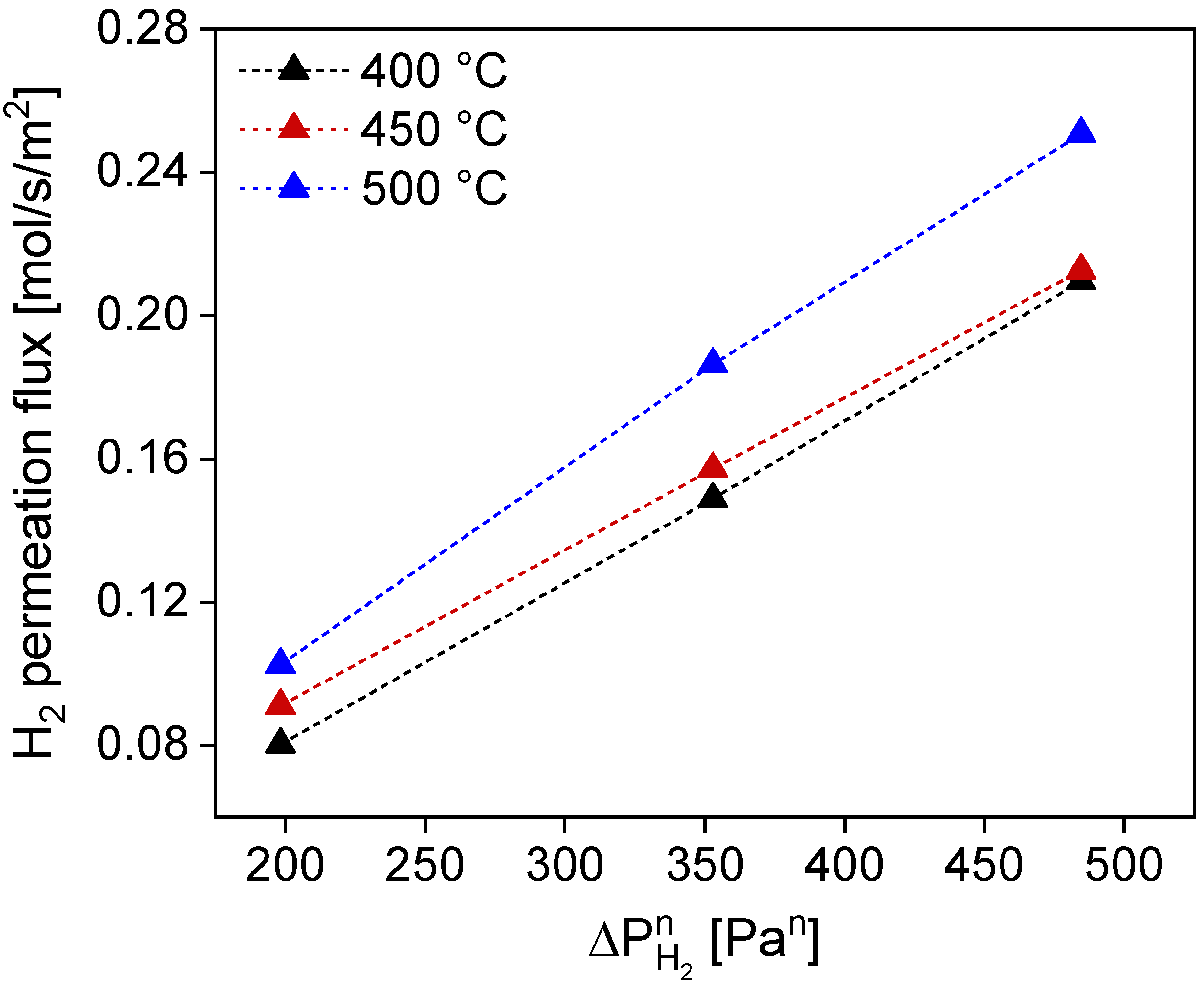
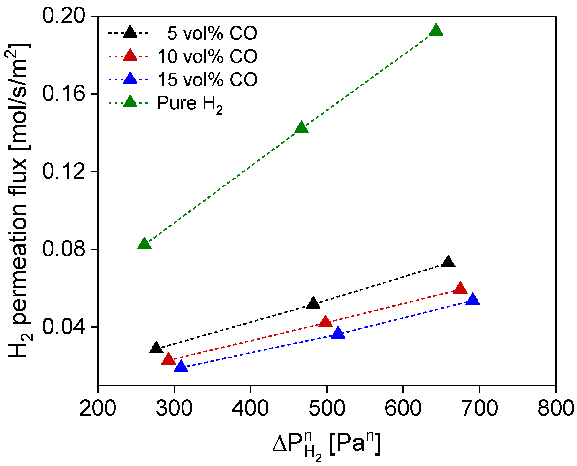
3.2. Membrane Testing

H2 and N2 permeance and the ideal H2/N2 selectivity of M2 are shown in Table 3. The H2 permeance exhibits the typical behavior for Pd–Ag films, showing an increased value at higher temperatures due to the activated nature of the solution diffusion mechanism for hydrogen permeation through Pd membranes. Meanwhile, the N2 permeance decreases with increasing temperature, exhibiting the presence of a Knudsen-type transport of N2 through possible isolated defects in the membrane and/or its welding parts between porous and dense metals. This consideration is further confirmed by the increase in N2 permeance with trans-membrane pressure, which increased with a positive slope from 5.5 × 10⁻¹¹ mol⋅s−1⋅m−2⋅Pa−1 (at 400 °C and 1 bar) to 9.3 × 10⁻¹¹ mol⋅s−1⋅m−2⋅Pa−1 (at 400 °C and 3 bar). However, since the N2 permeance is still extremely low, the increase in H2 permeation with temperature prevails, resulting in increasing H2/N2 selectivity at high temperatures.
The linear regression performed on the H2 permeation flux across the membrane as a function of temperature resulted in an n-exponent of 0.53 with an average Rsq of 0.999 for all considered temperatures (Figure 7). This value slightly deviates from the 0.5 exponents of a purely Sieverts-driven transport mechanism, highlighting the possible effect of the support (i.e., interdiffusion barrier and/or filler) on the hydrogen transport mechanism. The activation energy for this membrane amounts to 9265 J/mol, a value in the same order of magnitude as typical ones for metallic-supported membranes [23,38]. This value entails the contribution of activation energy of hydrogen transport through the Pd–Ag layer, through the interdiffusion barrier (mesoporous, which implies a lower activation energy value given by Knudsen-type transport), through the filler, and the porous metal support (both likely contributing with the viscous flow-type of transport) [19,36].
Following the single-gas tests, a CO/H2 binary-mixture fed to the membrane is analyzed to simulate the main permeating species during the steam methane reforming reaction. In Figure 8, the permeation flux of hydrogen is shown as a function of CO partial pressure. CO is well known to inhibit the Pd surface, occupying active sites for hydrogen splitting, significantly reducing the H2 permeation flow [54,55]. Furthermore, concentration polarization effects can occur, and both effects can synergically lower the H2 flux across the membrane [56,57]. In our case, a mass transfer limitation effect can be observed with decreasing H2 partial pressure and, therefore, increased CO concentration in the feed, with a progressively reduced H2 flow compared to the pure H2 permeation case. In the case of a H2 and CO mixture in the feed, the flow reduction, with respect to the pure H2 at 1 bar, 5% of CO in the feed, and 450 °C, amounts to 64.6%. This value implies a significant reduction that cannot solely be explained by mass transfer limitation effects. Firstly, the behavior of the hydrogen flux in the presence of CO was studied by fitting the CO/H2 binary-mixture tests with the model equation proposed by Barbieri et al. [54]:
H 2 p e r m e a n c e = ( 1 α T K C O P C O 1 + K C O P C O ) π 0 e E a R T
By assessing H2 permeance at two different CO partial pressures, it is possible to retrieve the α reduction factor and the Langmuir affinity KCO; however, since M2 is a very thin membrane (6–8 μm), mass transfer limitation effects are expected, which should be considered together with the depletion effect. To better decouple the mass transfer limitation and CO inhibition contributions, a model that predicts external mass transfer limitation effects (via a Sherwood correlation) and the depletion effect was developed. The effect of CO inhibition was then quantified by fitting the Langmuir–Sieverts with the developed model. Moreover, the use of the model allows for calculating the Langmuir parameters for CO inhibition, resulting in values of α = 0.56 and KCO = 5.7 × 10⁻⁵ Pa−1 (values that are in line with the literature values for similar types of membranes [54]).
The resulting CO inhibition curve (Figure 9a, red) initially shows a sharp reduction in H2 permeance with respect to pure H2 right after the introduction of 5% CO (CO partial pressure 10 kPa) and a less pronounced decrease in H2 permeance for CO partial pressures larger than ~10 kPa. This behavior suggests that for feed CO concentrations above 5%, the membrane surface is progressively saturated with CO, and the H2 flow reduction due to CO inhibition is less pronounced. On the other hand, by increasing the CO partial pressure, the mass transfer limitation effect proportionally increases (Figure 9a, green). This has already been reported for thicker membranes and explained with DFT calculations by Gallucci et al. [58]. These behaviors can be further observed in Figure 9b, where both contributions to H2 flow reduction are quantified. At the highest CO partial pressure (30 kPa, corresponding to 15% CO in the feed), the H2 permeance reduction due to CO inhibition corresponds to 59% with respect to the pure H2 gas, while the contribution due to the mass transfer limitation effect is 48%. Even though the CO inhibition contribution prevails, at larger CO partial pressures, it increases with a lower slope with respect to the mass transfer limitation contribution. On the other hand, the mass transfer limitation contribution to H2 flow reduction keeps proportionally increasing with a larger slope when CO partial pressure in the feed increases. This behavior further confirms the membrane’s progressive surface saturation with CO gas.
While performing CO/H2 binary-mixture tests, the presence of methane was detected in the permeating flow without any CO detection. In Figure 10, the presence of methane in the permeating flow is shown as a function of CO concentration in the feed flow. The CH4 in the permeating flow reached values close to 275 ppm at 500 °C and at a higher trans-membrane pressure. This behavior is in accordance with methanation reaction thermodynamics:
C O + 3 H 2 = C H 4 + H 2 O , H 0 = 206   k J / m o l
This is favored at high pressures and low temperatures (exothermic), with an almost complete CO conversion below 450 °C. The permeation of CO, which turns into CH4 in the permeate stream in the presence of H2, might indicate the presence of defects on the membrane surface, which expose the nickel–iron of the metallic support, which in turn could catalyze the methanation reaction (a methane presence was not previously detected with the ceramic-supported membranes tested in the same equipment, excluding possible catalytic activities of the stainless steel reactor and Swagelok stainless steel connections) [59].
The catalytic activity of the steel-based supports towards methanation was previously verified by Medrano et al. [21] by testing a bare, porous metallic support similar to the one employed in this work without any Pd–Ag layer. In their work, hydrogen conversion through the metallic support was detected. However, the direct presence of methane in the examined flow was not verified [21]. The presence of CH4 as a pollutant in the permeate stream is much less detrimental with respect to the poisoning effect of CO on most fuel cells and catalysts. Thus, the removal of CO from the H2 stream in the permeate side of the membrane reactor is a further advantage that results from the use of these metallic membrane supports.
In Table 4 and Table 5, the results of the MA-SMR studies are shown. In particular, the effects of the operating temperature and pressure on methane conversion, hydrogen recovery, and separation factors are listed. The methane conversion increases with the temperature, as expected for typical methane steam reforming processes. With the selected catalyst at the selected operating parameters, the thermodynamic equilibrium conversion is reached without the membrane (conventional process). Upon membrane installation, the thermodynamic equilibrium conversion of the conventional process is overcome for each of the investigated temperatures, with the highest conversion at 500 °C, where both membrane flux and reaction rates are faster. Similarly, to our previously investigated ammonia decomposition membrane reactor [35], the methane conversion configuration increases when increasing the trans-membrane pressure. This behavior is in contrast with what is expected from the conventional process, in which methane conversion decreases with increasing pressure due to thermodynamic constraints. However, in the case of a membrane reactor, the membrane’s presence counterbalances the detrimental pressure effect, which is beneficial for H2 permeation and increases the H2 removal contribution, owing to Le Chatelier’s principle [60].
Hydrogen recovery and separation factors are strictly correlated to the membrane’s performance. However, it is important to consider that the low achievable conversion at the selected operating conditions has a direct influence on the hydrogen recovery and separation factors, as well as the low membrane surface area considered in the study. Both HRF and SF increase when the operating trans-membrane pressure is increased due to the increased H2 permeation flux through the membrane. At the highest temperature and pressure (500 °C and 5 bar) 42.2% of the produced hydrogen passes through the membrane to the permeate side. This parameter can provide more of an indication for effective membrane performance as it accounts solely for the hydrogen produced by the process with its current methane conversion. The lower H2 permeance of the metallic-supported membrane, with respect to one of the ceramic relatives, directly influences the separation factor. Optimization on gas permeance increase across the membrane surface and/or installed membrane area increase will contribute to a large improvement for the separation factor and, in turn, hydrogen recovery and achievable CH4 conversion. Moreover, the presence of competing gases in the reaction zone and along the membrane surface (e.g., CO, CH4, H2O, CO2, N2) might significantly enhance the mass transfer limitations effects, decreasing the H2 permeating flux across the membrane [57]. All these parameters can be fine-tuned by means of dedicated membrane and membrane reactor modeling and design studies, which are beyond the scope of this work. Nevertheless, it can be affirmed that with the current membrane design, the thermodynamic conversion of the conventional process is surpassed for each of the explored reaction operating conditions, setting a starting point for further metallic-supported membrane optimization studies (Figure 11).
In Table 6, a comparison between this work and the work of Medrano et al. [21] (carried out using the same setup) is reported. In [21], the focus was on investigating the high-temperature stability of a metallic-supported membrane in fluidized-bed conditions. In our work, we chose similar operating parameters to compare the experimental results for our highly selective membrane in fixed-bed conditions at 500 °C. While most outcome reaction parameters result very similar (HRF and SF due to the low permeance of metallic-supported membranes), the conversion increase given by our reactor configuration is slightly higher, probably due to the different types of catalyst in our packed-bed configuration compared to the fluidized-bed configuration of Medrano et al. However, the most remarkable difference is constituted by the permeate stream composition, which accounts for 99.3% of H2 in the case of a highly selective membrane versus 97.6% for a low selectivity membrane. This difference can become relevant when the downstream application requires high-purity hydrogen (i.e., semiconductor manufacturing, fuel cells, or aerospace industry [61,62]), which can be achieved with improved membrane selectivity. Thus, these results highlight the importance of membrane optimization, which, in the case of metallic-supported membranes for SMR, calls for an increase in H2 permeance without H2 selectivity expenditures.

4. Conclusions

The modification of a rough metallic filter (0.5 μm media grade, 50 μm pore mouths) by polishing, opening the superficial pores by etching, and filling the pores by asymmetric deposition of the particles of α-Al2O3 (reported in our previous paper) has been successfully replicated in this work. The preparation procedure has been tuned by setting a suitable support pore size distribution peak target to ~100 nm after the filling procedure. The support was successfully used for the preparation of a 6 μm thick Pd–Ag selective layer. The reproduction method proved successful, guaranteeing membrane selectivity at 500 °C and 1 bar > ~10,000.
H2/CO mixture permeation tests showed an inhibition effect due to the presence of CO with a reduction in H2 permeance with respect to pure H2 gas, well in agreement with the behavior reported in the literature, which was successfully elucidated with a predictive mass transfer limitation model. Moreover, the presence of CH4 was detected in the permeate stream, confirming the membrane support’s catalytic activity towards the methanation reaction and, thus, the support’s ability to remove CO traces from the permeate stream (avoiding possible downstream PEM fuel cell poisoning).
The tests in the MA-SMR environment showed the ability to overcome the conventional process’ thermodynamic conversion of CH4 for all the explored operating conditions, promoting an increase in methane conversion with respect to a conventional process of up to 58% at 500 °C and 4 bar while guaranteeing at least 99.3% of hydrogen purity.
Overall, the selected preparation procedure and membrane reproduction method prove suitable for further optimization and utilization in membrane reactors, paving the way toward cheaper and easily scalable support options.

Supplementary Materials

The following supporting information can be downloaded at: https://www.mdpi.com/article/10.3390/pr12010040/s1, Supporting information about capillary flow porometry (CFP) is contained in the Supplementary Materials. Refs. [63,64,65,66] are cited in Supplementary Materials.

Author Contributions

Conceptualization, S.A.; methodology, S.A.; investigation, S.A.; resources, S.A. and W.J.R.V.; data curation, S.A.; writing—original draft preparation, S.A.; writing—review and editing, L.D.F., F.G. and A.P.T.; visualization, S.A.; supervision, L.D.F., F.G., A.P.T. and M.L.T.; project administration, F.G. and L.D.F.; funding acquisition, F.G. All authors have read and agreed to the published version of the manuscript.

Funding

This project has received funding from the European Union’s Horizon 2020 Research and Innovation Programme under grant agreement No. 869896 (MACBETH).Processes 12 00040 i001

Data Availability Statement

Data are available on request.

Conflicts of Interest

The authors declare no conflict of interest. The funders had no role in the design of the study, in the collection, analyses, or interpretation of data, in the writing of the manuscript, or in the decision to publish the results.

References

  1. Bockris, J.O. The hydrogen economy: Its history. Int. J. Hydrogen Energy 2013, 38, 2579–2588. [Google Scholar] [CrossRef]
  2. Aasberg-Petersen, K.; Hansen, J.-H.B.; Christensen, T.; Dybkjaer, I.; Christensen, P.; Nielsen, C.S.; Madsen, S.W.; Rostrup-Nielsen, J. Technologies for large-scale gas conversion. Appl. Catal. A Gen. 2001, 221, 379–387. [Google Scholar] [CrossRef]
  3. Dybkjaer, I. Tubular reforming and autothermal reforming of natural gas—An overview of available processes. Fuel Process. Technol. 1995, 42, 85–107. [Google Scholar] [CrossRef]
  4. Kim, C.-H.; Han, J.-Y.; Lim, H.; Lee, K.-Y.; Ryi, S.-K. Hydrogen production by steam methane reforming in membrane reactor equipped with Pd membrane deposited on NiO/YSZ/NiO multilayer-treated porous stainless steel. J. Membr. Sci. 2018, 563, 75–82. [Google Scholar] [CrossRef]
  5. Jokar, S.; Farokhnia, A.; Tavakolian, M.; Pejman, M.; Parvasi, P.; Javanmardi, J.; Zare, F.; Gonçalves, M.C.; Basile, A. The recent areas of applicability of palladium based membrane technologies for hydrogen production from methane and natural gas: A review. Int. J. Hydrogen Energy 2023, 48, 6451–6476. [Google Scholar] [CrossRef]
  6. Iulianelli, A.; Basile, A. Fuel and hydrogen treatment and production by membranes. In Current Trends and Future Developments on (Bio-) Membranes; Elsevier: Amsterdam, The Netherlands, 2020; pp. 91–108. [Google Scholar] [CrossRef]
  7. Bernardo, P.; Barbieri, G.; Drioli, E. Evaluation of membrane reactor with hydrogen-selective membrane in methane steam reforming. Chem. Eng. Sci. 2010, 65, 1159–1166. [Google Scholar] [CrossRef]
  8. Bernardo, G.; Araújo, T.; Lopes, T.d.S.; Sousa, J.; Mendes, A. Recent advances in membrane technologies for hydrogen purification. Int. J. Hydrogen Energy 2019, 45, 7313–7338. [Google Scholar] [CrossRef]
  9. Bosko, M.; Múnera, J.; Lombardo, E.; Cornaglia, L. Dry reforming of methane in membrane reactors using Pd and Pd–Ag composite membranes on a NaA zeolite modified porous stainless steel support. J. Membr. Sci. 2010, 364, 17–26. [Google Scholar] [CrossRef]
  10. Marquez-Ruiz, A.; Wu, J.; Özkan, L.; Gallucci, F.; Annaland, M.V.S. Optimal Operation and Control of Fluidized Bed Membrane Reactors for Steam Methane Reforming. Comput. Aided Chem. Eng. 2019, 46, 1231–1236. [Google Scholar] [CrossRef]
  11. Anzelmo, B.; Wilcox, J.; Liguori, S. Natural gas steam reforming reaction at low temperature and pressure conditions for hydrogen production via Pd/PSS membrane reactor. J. Membr. Sci. 2017, 522, 343–350. [Google Scholar] [CrossRef]
  12. Dittmar, B.; Behrens, A.; Schödel, N.; Rüttinger, M.; Franco, T.; Straczewski, G.; Dittmeyer, R. Methane steam reforming operation and thermal stability of new porous metal supported tubular palladium composite membranes. Int. J. Hydrogen Energy 2013, 38, 8759–8771. [Google Scholar] [CrossRef]
  13. Karakiliç, P.; Huiskes, C.; Luiten-Olieman, M.W.; Nijmeijer, A.; Winnubst, L. Sol-gel processed magnesium-doped silica membranes with improved H2/CO2 separation. J. Membr. Sci. 2017, 543, 195–201. [Google Scholar] [CrossRef]
  14. Castricum, H.L.; Qureshi, H.F.; Nijmeijer, A.; Winnubst, L. Hybrid silica membranes with enhanced hydrogen and CO2 separation properties. J. Membr. Sci. 2015, 488, 121–128. [Google Scholar] [CrossRef]
  15. Nijmeijer, A.; Kruidhof, H.; Bredesen, R.; Verweij, H. Preparation and Properties of Hydrothermally Stable γ-Alumina Membranes. J. Am. Ceram. Soc. 2001, 84, 136–140. [Google Scholar] [CrossRef]
  16. Al-Mufachi, N.; Rees, N.; Steinberger-Wilkens, R. Hydrogen selective membranes: A review of palladium-based dense metal membranes. Renew. Sustain. Energy Rev. 2015, 47, 540–551. [Google Scholar] [CrossRef]
  17. Nam, S.-E.; Lee, K.-H. Hydrogen separation by Pd alloy composite membranes: Introduction of diffusion barrier. J. Membr. Sci. 2001, 192, 177–185. [Google Scholar] [CrossRef]
  18. Bonekamp, B. Preparation of asymmetric ceramic membrane supports by dip-coating. In Membrane Science and Technology; Burggraaf, A.J., Cot, L., Eds.; Elsevier: Amsterdam, The Netherlands, 1996; Chapter 6; Volume 4, pp. 141–225. [Google Scholar] [CrossRef]
  19. Arratibel, A.; Tanaka, A.P.; Laso, I.; Annaland, M.V.S.; Gallucci, F. Development of Pd-based double-skinned membranes for hydrogen production in fluidized bed membrane reactors. J. Membr. Sci. 2018, 550, 536–544. [Google Scholar] [CrossRef]
  20. Guo, Y.; Wu, H.; Jin, Y.; Zhou, L.; Chen, Q.; Fan, X. Deposition of TS-1 zeolite film on palladium membrane for enhancement of membrane stability. Int. J. Hydrogen Energy 2017, 42, 27111–27121. [Google Scholar] [CrossRef]
  21. Medrano, J.A.; Fernandez, E.; Melendez, J.; Parco, M.; Tanaka, D.A.P.; Annaland, M.V.S.; Gallucci, F. Pd-based metallic supported membranes: High-temperature stability and fluidized bed reactor testing. Int. J. Hydrogen Energy 2016, 41, 8706–8718. [Google Scholar] [CrossRef]
  22. de Nooijer, N.; Plazaola, A.A.; Rey, J.M.; Fernandez, E.; Tanaka, D.A.P.; Annaland, M.V.S.; Gallucci, F. Long-Term Stability of Thin-Film Pd-Based Supported Membranes. Processes 2019, 7, 106. [Google Scholar] [CrossRef]
  23. Agnolin, S.; Melendez, J.; Di Felice, L.; Gallucci, F. Surface roughness improvement of Hastelloy X tubular filters for H2 selective supported Pd–Ag alloy membranes preparation. Int. J. Hydrogen Energy 2022, 47, 28505–28517. [Google Scholar] [CrossRef]
  24. Agnolin, S.; Apostolo, F.; Di Felice, L.; Rey, J.M.; Tanaka, A.P.; Tanco, M.L.; Gallucci, F. Development of selective Pd–Ag membranes on porous metal filters. Int. J. Hydrogen Energy 2023, 48, 25398–25409. [Google Scholar] [CrossRef]
  25. Liu, J.; Ju, X.; Tang, C.; Liu, L.; Li, H.; Chen, P. High performance stainless-steel supported Pd membranes with a finger-like and gap structure and its application in NH3 decomposition membrane reactor. Chem. Eng. J. 2020, 388, 124245. [Google Scholar] [CrossRef]
  26. Guazzone, F.; Engwall, E.E.; Ma, Y.H. Effects of surface activity, defects and mass transfer on hydrogen permeance and n-value in composite palladium-porous stainless steel membranes. Catal. Today 2006, 118, 24–31. [Google Scholar] [CrossRef]
  27. Macedo, M.S.; Uriarte, N.A.; Soria, M.; Madeira, L.M.; Calles, J.; Sanz, R.; Alique, D. Effect of ceria particle size as intermediate layer for preparation of composite Pd-membranes by electroless pore-plating onto porous stainless-steel supports. Sep. Purif. Technol. 2023, 327, 124932. [Google Scholar] [CrossRef]
  28. Xu, N.; Ryi, S.; Li, A.; Grace, J.R.; Lim, J.; Boyd, T. Improved pre-treatment of porous stainless steel substrate for preparation of Pd-based composite membrane. Can. J. Chem. Eng. 2013, 91, 1695–1701. [Google Scholar] [CrossRef]
  29. Mardilovich, I.P.; Engwall, E.; Ma, Y.H. Dependence of hydrogen flux on the pore size and plating surface topology of asymmetric Pd-porous stainless steel membranes. Desalination 2002, 144, 85–89. [Google Scholar] [CrossRef]
  30. Nayebossadri, S.; Fletcher, S.; Speight, J.D.; Book, D. Hydrogen permeation through porous stainless steel for palladium-based composite porous membranes. J. Membr. Sci. 2016, 515, 22–28. [Google Scholar] [CrossRef]
  31. Augustine, A.S.; Mardilovich, I.P.; Kazantzis, N.K.; Ma, Y.H. Durability of PSS-supported Pd-membranes under mixed gas and water–gas shift conditions. J. Membr. Sci. 2012, 415–416, 213–220. [Google Scholar] [CrossRef]
  32. Ayturk, M.E.; Mardilovich, I.P.; Engwall, E.E.; Ma, Y.H. Synthesis of composite Pd-porous stainless steel (PSS) membranes with a Pd/Ag intermetallic diffusion barrier. J. Membr. Sci. 2006, 285, 385–394. [Google Scholar] [CrossRef]
  33. Sanz, R.; Calles, J.; Alique, D.; Furones, L. New synthesis method of Pd membranes over tubular PSS supports via “pore-plating” for hydrogen separation processes. Int. J. Hydrogen Energy 2012, 37, 18476–18485. [Google Scholar] [CrossRef]
  34. Lee, J.-H.; Han, J.-Y.; Kim, K.-M.; Ryi, S.-K.; Kim, D.-W. Development of homogeneous Pd–Ag alloy membrane formed on porous stainless steel by multi-layered films and Ag-upfilling heat treatment. J. Membr. Sci. 2015, 492, 242–248. [Google Scholar] [CrossRef]
  35. Cechetto, V.; Agnolin, S.; Di Felice, L.; Tanaka, A.P.; Tanco, M.L.; Gallucci, F. Metallic Supported Pd-Ag Membranes for Simultaneous Ammonia Decomposition and H2 Separation in a Membrane Reactor: Experimental Proof of Concept. Catalysts 2023, 13, 920. [Google Scholar] [CrossRef]
  36. Fernandez, E.; Medrano, J.A.; Melendez, J.; Parco, M.; Viviente, J.L.; Annaland, M.V.S.; Gallucci, F.; Tanaka, D.P. Preparation and characterization of metallic supported thin Pd–Ag membranes for hydrogen separation. Chem. Eng. J. 2016, 305, 182–190. [Google Scholar] [CrossRef]
  37. van Dal, M.; Pleumeekers, M.; Kodentsov, A.; van Loo, F. Intrinsic diffusion and Kirkendall effect in Ni–Pd and Fe–Pd solid solutions. Acta Mater. 2000, 48, 385–396. [Google Scholar] [CrossRef]
  38. Bottino, A.; Broglia, M.; Capannelli, G.; Comite, A.; Pinacci, P.; Scrignari, M.; Azzurri, F. Sol–gel synthesis of thin alumina layers on porous stainless steel supports for high temperature palladium membranes. Int. J. Hydrogen Energy 2013, 39, 4717–4724. [Google Scholar] [CrossRef]
  39. Chotirach, M.; Tantayanon, S.; Tungasmita, S.; Kriausakul, K. Zr-based intermetallic diffusion barriers for stainless steel supported palladium membranes. J. Membr. Sci. 2012, 405–406, 92–103. [Google Scholar] [CrossRef]
  40. Yepes, D.; Cornaglia, L.; Irusta, S.; Lombardo, E. Different oxides used as diffusion barriers in composite hydrogen permeable membranes. J. Membr. Sci. 2006, 274, 92–101. [Google Scholar] [CrossRef]
  41. Calles, J.; Sanz, R.; Alique, D. Influence of the type of siliceous material used as intermediate layer in the preparation of hydrogen selective palladium composite membranes over a porous stainless steel support. Int. J. Hydrogen Energy 2012, 37, 6030–6042. [Google Scholar] [CrossRef]
  42. Mateos-Pedrero, C.; Soria, M.A.; Rodríguez-Ramos, I.; Guerrero-Ruiz, A. Modifications of Porous Stainless Steel Previous to the Synthesis of Pd Membranes; Elsevier Masson SAS: Amsterdam, The Netherlands, 2010; Volume 175. [Google Scholar]
  43. Kim, T.-W.; Lee, E.-H.; Byun, S.; Seo, D.-W.; Hwang, H.-J.; Yoon, H.-C.; Kim, H.; Ryi, S.-K. Highly selective Pd composite membrane on porous metal support for high-purity hydrogen production through effective ammonia decomposition. Energy 2022, 260, 125209. [Google Scholar] [CrossRef]
  44. Tong, J.; Matsumura, Y.; Suda, H.; Haraya, K. Thin and dense Pd/CeO2/MPSS composite membrane for hydrogen separation and steam reforming of methane. Sep. Purif. Technol. 2005, 46, 1–10. [Google Scholar] [CrossRef]
  45. Ma, Y.H.; Akis, B.C.; Ayturk, M.E.; Guazzone, F.; Engwall, E.E.; Mardilovich, I.P. Characterization of Intermetallic Diffusion Barrier and Alloy Formation for Pd/Cu and Pd/Ag Porous Stainless Steel Composite Membranes. Ind. Eng. Chem. Res. 2003, 43, 2936–2945. [Google Scholar] [CrossRef]
  46. Bosko, M.L.; Miller, J.B.; Lombardo, E.A.; Gellman, A.J.; Cornaglia, L.M. Surface characterization of Pd–Ag composite membranes after annealing at various temperatures. J. Membr. Sci. 2011, 369, 267–276. [Google Scholar] [CrossRef]
  47. Qiao, A.; Zhang, K.; Tian, Y.; Xie, L.; Luo, H.; Lin, Y.; Li, Y. Hydrogen separation through palladium–copper membranes on porous stainless steel with sol–gel derived ceria as diffusion barrier. Fuel 2010, 89, 1274–1279. [Google Scholar] [CrossRef]
  48. Huang, Y.; Dittmeyer, R. Preparation of thin palladium membranes on a porous support with rough surface. J. Membr. Sci. 2007, 302, 160–170. [Google Scholar] [CrossRef]
  49. Huang, Y.; Dittmeyer, R. Preparation and characterization of composite palladium membranes on sinter-metal supports with a ceramic barrier against intermetallic diffusion. J. Membr. Sci. 2006, 282, 296–310. [Google Scholar] [CrossRef]
  50. Katoh, M.; Ueshima, T.; Takatani, M.; Sugiura, H.; Ominami, K.; Sugiyama, S. Effects of different silica intermediate layers for hydrogen diffusion enhancement of palladium membranes applied to porous stainless steel support. Sci. Rep. 2020, 10, 1–12. [Google Scholar] [CrossRef]
  51. Tarditi, A.; Gerboni, C.; Cornaglia, L. PdAu membranes supported on top of vacuum-assisted ZrO2-modified porous stainless steel substrates. J. Membr. Sci. 2013, 428, 1–10. [Google Scholar] [CrossRef]
  52. Tanaka, D.A.P.; Tanco, M.A.L.; Okazaki, J.; Wakui, Y.; Mizukami, F.; Suzuki, T.M. Preparation of “pore-fill” type Pd–YSZ–γ-Al2O3 composite membrane supported on α-Al2O3 tube for hydrogen separation. J. Membr. Sci. 2008, 320, 436–441. [Google Scholar] [CrossRef]
  53. Tanis-Kanbur, M.B.; Peinador, R.I.; Calvo, J.I.; Hernández, A.; Chew, J.W. Porosimetric membrane characterization techniques: A review. J. Membr. Sci. 2021, 619, 118750. [Google Scholar] [CrossRef]
  54. Barbieri, G.; Scura, F.; Lentini, F.; Deluca, G.; Drioli, E. A novel model equation for the permeation of hydrogen in mixture with carbon monoxide through Pd–Ag membranes. Sep. Purif. Technol. 2008, 61, 217–224. [Google Scholar] [CrossRef]
  55. Caravella, A.; Scura, F.; Barbieri, G.; Drioli, E. Inhibition by CO and polarization in pd-based membranes: A novel permeation reduction coefficient. J. Phys. Chem. B 2010, 114, 12264–12276. [Google Scholar] [CrossRef] [PubMed]
  56. Helmi, A.; Voncken, R.; Raijmakers, A.; Roghair, I.; Gallucci, F.; Annaland, M.V.S. On concentration polarization in fluidized bed membrane reactors. Chem. Eng. J. 2018, 332, 464–478. [Google Scholar] [CrossRef]
  57. Boon, J.; Pieterse, J.; van Berkel, F.; van Delft, Y.; Annaland, M.V.S. Hydrogen permeation through palladium membranes and inhibition by carbon monoxide, carbon dioxide, and steam. J. Membr. Sci. 2015, 496, 344–358. [Google Scholar] [CrossRef]
  58. Gallucci, F.; Chiaravalloti, F.; Tosti, S.; Drioli, E.; Basile, A. The effect of mixture gas on hydrogen permeation through a palladium membrane: Experimental study and theoretical approach. Int. J. Hydrogen Energy 2007, 32, 1837–1845. [Google Scholar] [CrossRef]
  59. Fernandez, E.; Helmi, A.; Coenen, K.; Melendez, J.; Viviente, J.L.; Tanaka, D.A.P.; Annaland, M.V.S.; Gallucci, F. Development of thin Pd–Ag supported membranes for fluidized bed membrane reactors including WGS related gases. Int. J. Hydrogen Energy 2015, 40, 3506–3519. [Google Scholar] [CrossRef]
  60. Matsumura, Y.; Tong, J. Methane Steam Reforming in Hydrogen-permeable Membrane Reactor for Pure Hydrogen Production. Top. Catal. 2008, 51, 123–132. [Google Scholar] [CrossRef]
  61. Paglieri, S.N.; Way, J.D. Innovations in palladium membrane research. Sep. Purif. Methods 2002, 31, 1–169. [Google Scholar] [CrossRef]
  62. Moseley, P.T. Fuel Cell Systems Explained. J. Power Source 2001, 93, 285. [Google Scholar] [CrossRef]
  63. Tanis-Kanbur, M.B.; Peinador, R.I.; Hu, X.; Calvo, J.I.; Chew, J.W. Membrane characterization via evapoporometry (EP) and liquid-liquid displacement porosimetry (LLDP) techniques. J. Membr. Sci. 2019, 586, 248–258. [Google Scholar] [CrossRef]
  64. Li, D.; Frey, M.W.; Joo, Y.L. Characterization of nanofibrous membranes with capillary flow porometry. J. Membr. Sci. 2006, 286, 104–114. [Google Scholar] [CrossRef]
  65. Gribble, C.M.; Matthews, G.P.; Laudone, G.M.; Turner, A.; Ridgway, C.J.; Schoelkopf, J.; Gane, P.A. Porometry, porosimetry, image analysis and void network modelling in the study of the pore-level properties of filters. Chem. Eng. Sci. 2011, 66, 3701–3709. [Google Scholar] [CrossRef]
  66. Kolb, H.; Schmitt, R.; Dittler, A.; Kasper, G. On the accuracy of capillary flow porometry for fibrous filter media. Sep. Purif. Technol. 2018, 199, 198–205. [Google Scholar] [CrossRef]
Figure 1. Picture of prepared Pd–Ag membrane (M2) for SMR studies.
Processes 12 00040 g001
Figure 2. Steam methane reforming setup. (1) Gas feeding system (CO, N2, H2, CH4, and air via Bronkhorst mass flow controllers); (2) controlled evaporation system for steam feed; (3) membrane reactor; (4) condensation system; (5) analysis zone (Micro GC and Horiba Bubble flowmeters).
Processes 12 00040 g002
Figure 3. Surface morphology imaging via laser-optical confocal microscopy and height distribution view of (a) a superficial pore mouth on M2 support, asymmetrically filled with α-Al2O3 of decreasing particle size; (b) a superficial pore mouth on M2 support, asymmetrically filled with α-Al2O3 of decreasing particle size and equipped with a γ-Al2O3 interdiffusion barrier.
Processes 12 00040 g003
Figure 4. Cross-sectional SEM of S2 porous Hastelloy-X support filled asymmetrically with α-Al2O3 of decreasing particle size.
Processes 12 00040 g004
Figure 5. Pore diameter distribution shift, retrieved via CFP, of M2 support after multiple filling cycles with α-Al2O3 particles of 18, 5, and 1.5 μm, compared with reference target M1 [35].
Processes 12 00040 g005
Figure 6. Cross-sectional SEM imaging of a 6–8 µm thick Pd–Ag layer, obtained via a double 5 h electroless plating procedure on the Hastelloy-X support equipped with γ-Al2O3 interdiffusion barrier (S3).
Processes 12 00040 g006
Figure 7. Linear regression on H2 permeating flux across the membrane under pure gas permeation conditions at different temperatures. Exponent n can be retrieved by considering the best fit for all explored temperatures.
Processes 12 00040 g007
Figure 8. H2 permeation flux under CO/H2 binary-mixture test conditions, evaluated at 450 °C with 5, 10, and 15% of CO in the feed flow and compared with pure H2 permeation case.
Processes 12 00040 g008
Figure 9. (a) H2 permeance as a function of different CO partial pressures at 450 °C and 2 bar total pressure. Comparison between experimental data points (black) and estimated points calculated with (1) fit parameters K0 and α, according to Equation (7) of the Sieverts–Langmuir model by Barbieri et al. (black, dashed); (2) predictive mass transfer limitation model by Ververs et al. (blue); and (3) sole CO inhibition contribution (red). (b) H2 permeance reduction given by CO inhibition (red) and mass transfer limitations (blue).
Processes 12 00040 g009
Figure 10. Methane concentration in the permeate stream as a function of CO concentration in the feed flow, evaluated at 1, 2, and 3 barg trans-membrane pressure and 500 °C.
Processes 12 00040 g010
Figure 11. Methane conversion of the M2A-SMR compared with conventional SMR experimental campaign and calculated thermodynamic equilibrium conversion for conventional SMR at 400, 450, and 500 °C and reference pressure conditions (4 bar).
Processes 12 00040 g011
Table 1. Prepared supports and their modifications.
SupportPolishingEtchingFilling with α-Al2O3Ɣ-Al2O3
Layer
Pd–Ag
2 Layers
18 µm5 µm1.5 µm
M2YesYesYesYesYesYesYes
S2YesYesYesYesYes----
S3YesYes------YesYes
Table 2. Explored experimental conditions for single-gas permeation tests, binary-mixture permeation tests, and MA-SMR reaction tests. For SMR, a reference case without membrane was investigated at 4 bars for each examined temperature.
Single-Gas Permeation Tests
Single gases investigatedH2, N2
Temperature (°C)400, 450, 500
Retentate Pressure (bar)2, 3, 4
Permeate Pressure (bar)1
Binary-mixture permeation tests
Binary mixtureCO/H2
Temperature (°C)400, 450, 500
Retentate Pressure (bar)2, 3, 4
Permeate Pressure (bar)1
CO in feed (vol%)5, 10, 15
Methane steam reforming
Membrane-assistedConventional
Temperature (°C)400, 450, 500400, 450, 500
Retentate Pressure (bar)2, 3, 4, 54
Permeate Pressure (-)vacuum-
CH4 in feed (%v/v)2424
Steam to Carbon ratio (-)3:13:1
Table 3. H2 permeance, N2 permeance, and ideal H2 selectivity of M2 at 400, 450, and 500 °C and 1 bar trans-membrane pressure.
Temperature
(°C)
H2 Permeance
(mol/s/m2/Pa)
N2 Permeance
(mol/s/m2/Pa)
H2/N2
Ideal Selectivity
(-)
4006.3 × 10−75.5 × 10−1111,454
4506.4 × 10−73.8 × 10−1116,842
5007.5 × 10−73.7 × 10−1120,270
Table 4. SMR temperature behavior: CH4 conversion, HRF, and SF evaluated at 4 bar and 400, 450, and 500 °C both for conventional and MA-SMR.
CalculatedConventionalMembrane Reactor
TThermodynamic Equilibrium ConversionCH4
Conversion
CH4
Conversion
H2
Recovery
Separation Factor
(°C)(%)(%)(%)(%)(%)
40011.810.115.31.58.8
45018.218.231.810.731.6
50026.726.742.113.932.5
Table 5. SMR pressure behavior: CH4 conversion, HRF, and SF evaluated at 500 °C and 2, 3, 4, and 5 bar both for conventional and MA-SMR.
CalculatedConventionalMembrane Reactor
PThermodynamic Equilibrium ConversionCH4
Conversion
CH4
Conversion
H2
Recovery
Separation Factor
(Bar)(%)(%)(%)(%)(%)
234.4-39.010.419.4
329.7-39.912.626.2
426.726.742.113.932.5
524.6-52.415.442.2
Table 6. Comparison between the main reaction performance indicators of the M2-assisted SMR in fixed-bed configuration reported in this work and the membrane-assisted SMR in fluidized-bed configuration reported in previous work.
This WorkMedrano et al. [21]
Reactor
ConfigurationFixed bedFluidized bed
Catalyst2%wt Rh/Al2O3, 300 gNiO/CaAl2O4, 300 g
Ghsv (L × min−1 × gcat−1)0.0120.012–0.017
Membrane
ConfigurationSupported tubular
Pd-based membrane
Supported tubular
Pd-based membrane
Support (-)Metallic
(Hastelloy-X, 0.5 μm MG, Hebei Golden Flame Wire Mesh Co., Hengshui, China)
Metallic
(Hastelloy-X, 0.1 μm MG, pre-treated)
Selective layer composition (-)Pd–AgPd–Ag
Selective layer thickness (μm) ~ 6–8 ~ 6–8 *
Length
(mm)
90137
H2 permeance before SMR
(at 450 °C and 1 barg) (mol/s/m2/Pa)
6.4 × 10−78.6 × 10−7
H2/N2 ideal perm-selectivity before SMR
(at 450 °C and 1 barg)
(-)
16,842574
CH4 conversion increase (%)
T = 500 °C, 4 bar5846 **
H2 recovery factor (%)
T = 500 °C, 4 bar1417 **
H2 separation factor (%)
T = 500 °C, 4 bar3335 **
H2 in permeate side (%)
T = 500 °C, 4 bar99.397.6
* Derived from SEM imaging in the manuscript.** Derived from manuscript’s plots analysis.
Disclaimer/Publisher’s Note: The statements, opinions and data contained in all publications are solely those of the individual author(s) and contributor(s) and not of MDPI and/or the editor(s). MDPI and/or the editor(s) disclaim responsibility for any injury to people or property resulting from any ideas, methods, instructions or products referred to in the content.

