Article

High-Temperature and Pressure Downhole Safety Valve Performance Envelope Curve Study

1
CNPC Engineering Technology R&D Co., Ltd., Beijing 102206, China
2
School of Mechatronic Engineering, Southwest Petroleum University, Chengdu 610500, China
*
Author to whom correspondence should be addressed.
Processes 2023, 11(9), 2525; https://doi.org/10.3390/pr11092525
Submission received: 21 July 2023 / Revised: 11 August 2023 / Accepted: 14 August 2023 / Published: 23 August 2023

Abstract

:
The introduction of downhole safety valve performance envelope curves can effectively prevent the failure of the downhole safety valves during field operations. The method of drawing the performance envelope curve of high-temperature and pressure downhole safety value was proposed based on the mechanical properties of the downhole safety valve. The numerical simulation method was used for the mechanical performance of the downhole safety valve, and the stress change law of the overall structure of the downhole safety valve under the ultimate load was obtained. The ultimate bearing state and the failure threshold stress value of the key components of the downhole safety valve were further determined. The performance envelope curve of the downhole safety valve was finally completed. The results of the study show that the downhole safety value envelope curve can be obtained by studying the mechanical properties of the downhole safety valve, and each section of the envelope curve corresponded to the cause of failure of the downhole safety valve, giving the theoretical calculation idea of the downhole safety valve performance envelope curve. This study provides theoretical and methodological support for the study of the performance envelope curves of the downhole safety valves, packers, and other complex working conditions of downhole tools and their application in the field.

1. Introduction

With the large-scale exploration and development of oilfields, oil and gas wells are characterized by ultra-deep, ultra-high pressure, high-temperature, and high sulfur content. Due to the special nature and complexity of the downhole environment, the safe and stable operation of downhole equipment becomes crucial. As an important link in downhole devices, the safety of the downhole safety valves not only affects the operation but is also closely related to the safety of wells [1,2,3]. Therefore, downhole safety valve performance envelope curve research is carried out to accurately characterize the application boundaries of safety valves under different working conditions, and it provides an effective basis for the application of the downhole safety valves in high-temperature, high pressure, high sulfur content, and high production gas wells. The downhole safety valve performance envelope curve can effectively guide the application of the downhole safety valves in the field, which is of great significance for research regarding the downhole safety valves.
In order to ensure the safety and reliability of the downhole safety valves, numerous studies have been conducted on the structural strength analysis and reliability of the downhole safety valves. However, there is no direct literature on the subject of performance envelope curves for downhole safety valves. Fan et al. [4] aimed at the internal leakage of the sealing surface of the spring-type nuclear safety valve and studied the characteristics of the flow field and sound field when the leakage height between the disc and the sealing surface of the valve seat is 0.5 mm. Based on the large eddy simulation (LES) and the Morin acoustic simulation method, numerical simulations were carried out. Lu et al. [5] established the instantaneous impact model and determined the load of the valve plate according to the actual working conditions of the downhole safety valve. The strength requirement of valve plate design and the necessity and applicable conditions of valve plate buffer mechanism were obtained. Liu et al. [6] took the common tubing portable downhole safety valve as the object and the key mechanical properties, such as working pressure, ground control pressure, and full opening, and carried out measurements of full closing pressure, maximum running depth, and self-balancing ability. Wang et al. [7] provided a basis for the selection and treatment of the downhole safety valves by comparing the structures of different types of the downhole safety valves. Gao et al. [8] introduced the packer performance envelope curve and, by combining this curve with string mechanics, effectively prevented packer failure during field construction. Cody Leeheng et al. [9] not only put forward a new viewpoint on curvature properties but also on the transfer properties between envelope curves embedded in rigid bodies. A kinematic model based on instantaneous central motion is proposed to describe the point transfer rate. The detailed curvature and transfer characteristics of the line envelope and the circle envelope are given. A successful operating envelope for various elastomer seals exists in the energy industry. Through the above investigation, it is found that there is no reliable theoretical basis for drawing the performance envelope curve of the downhole safety valves at present. The mechanism related to the plotting of the downhole safety valve performance envelope curves is currently unknown.
Aiming to address the above needs, the research on the performance envelope curve of the downhole safety valves is carried out. In this study, we will carry out research by combining theory and simulation. Based on the principle of drawing the performance envelope curve of the downhole safety valve, a numerical simulation method will be adopted to simulate the mechanical performance of the downhole safety valve. The mechanical distribution law of the downhole safety valve will be obtained by analyzing the simulation results, and the ultimate bearing state of the key components of the downhole safety valve will be determined. Furthermore, the performance envelope curve of the downhole safety valve will be drawn. This study can provide data reference and theoretical guidance for the design and application of subsequent downhole safety valves and other downhole tools.

2. Downhole Safety Valve Performance Envelope Plotting Method

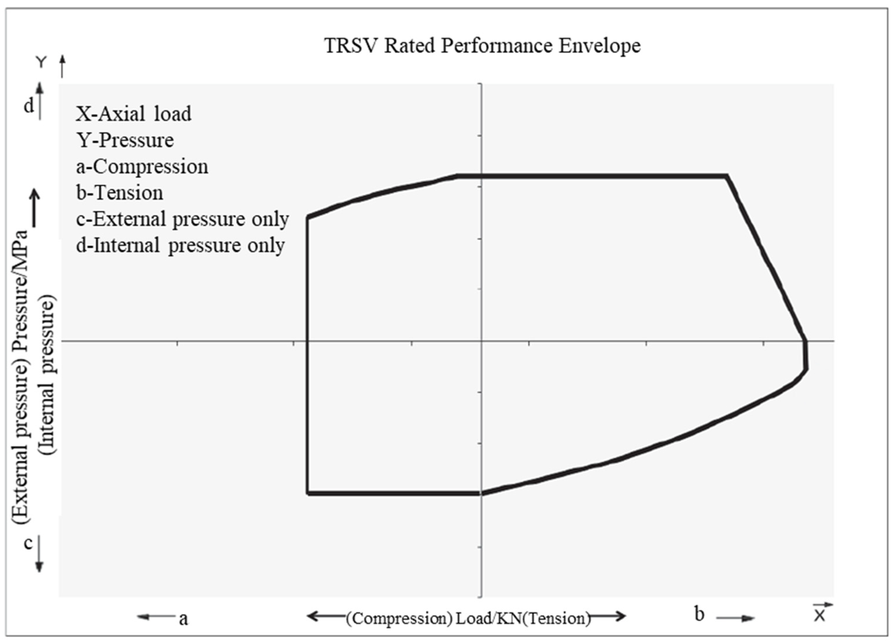
2.1. Drawing Principles
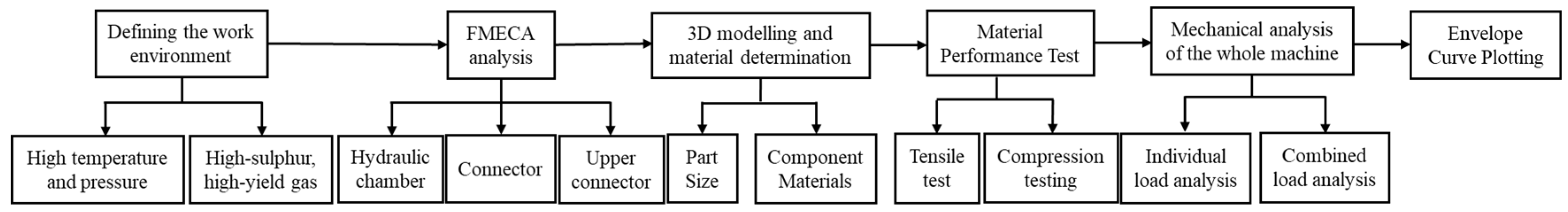
The envelope curve of a downhole safety valve can provide operators with a safe working area and failure area of the downhole safety valve [10,11,12]. The theoretical envelope curve of the tubing-retrievable safety valve (TRSV) is shown in Figure 1. Specifically, the envelope curve of a downhole safety valve is a closed, two-dimensional curve of the downhole safety valve under the limited state of the internal pressure, external pressure, tensile load, and compression load. The envelope curve of the downhole safety valve includes four quadrants. The first quadrant is tensile load and internal pressure. The second quadrant is internal pressure and compression load. The third quadrant is external pressure and compressive load. The fourth quadrant is tensile load and external pressure.
The downhole safety valve envelope curve is a good tool for grasping and predicting downhole safety valve performance and the possible causes of failure. This information can be used to compare product parameters and facilitate the rational selection of the downhole safety valves for application in the field.

2.2. Drawing Steps

The study of common failure forms of the downhole safety valves is the basis for analyzing, calculating and drawing the performance envelope curve of the downhole safety valves. Downhole safety valve performance envelope curve drawing needs at least six steps [13,14,15]. The drawing process is shown in Figure 2.
(a)
Determining the work environment
The key to drawing the performance envelope curve of the downhole safety valves is the failure point of different components under combined loads. The key to determining the failure point lies in the loads that different components are subjected to, so the operating conditions of the downhole safety valves must be clarified. This study focuses on downhole safety valves under high-temperature, high-pressure, high sulfur content, and high production gas well operating environments.
(b)
Failure modes, effects, and criticality analysis (FMECA)
FMECA is carried out to determine the failure points of critical components. By determining the operating environment of a downhole safety valve, different critical components can be simulated and analyzed. The loads that can be sustained under different load combinations and extreme operating conditions can be obtained and the failure point of each critical component can be determined.
(c)
3D modelling and material determination
In establishing the three-dimensional model of the downhole safety valve, the first thing to consider is the exact size of each component, as well as the material properties required to manufacture each component. As the downhole safety valve performance envelope curve is drawn, the aim is to determine the failure point of each component under different combinations of loads. Therefore, it is essential to determine the exact dimensions of the downhole safety valve and the mechanical properties of the materials used to manufacture it.
(d)
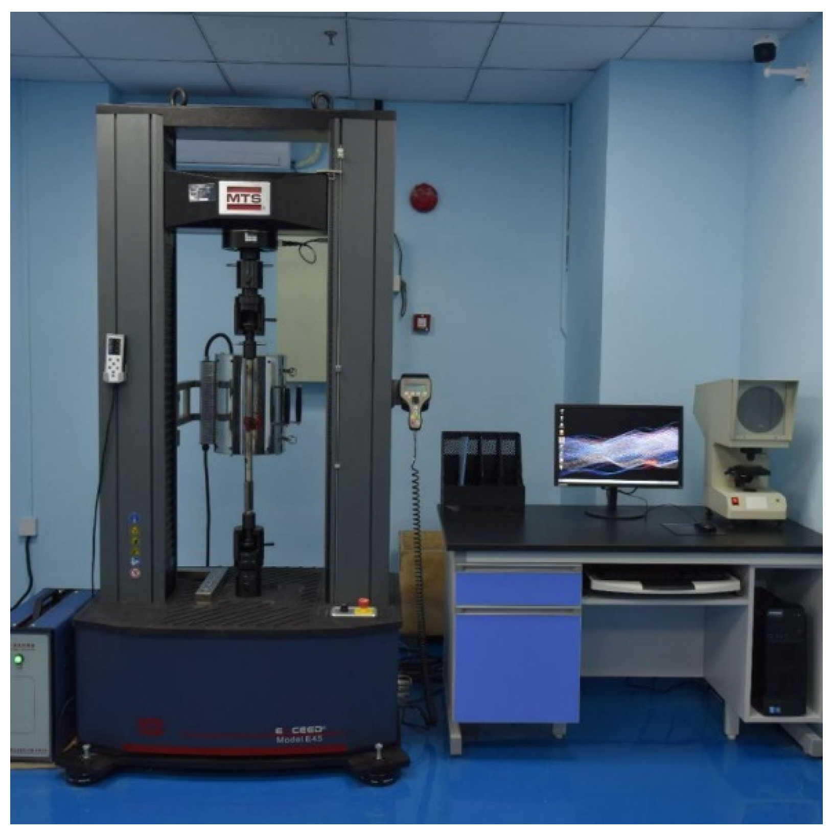
Material performance test
Standard tensile or compression specimens are prepared using high-temperature and pressure downhole safety valve upper joints, lower joints, connecting cylinders, and other constituent materials, as well as high-temperature tensile and compression tests on the constituent materials. According to the results of the tensile and compression test, calculate the elastic modulus and elastic tensile strength of the downhole safety valve materials.
(e)
Mechanical analysis of the whole machine
A full-size finite element simulation model of the working behavior of the downhole safety valve is established to simulate and analyze the mechanical behavior of the downhole safety valve in the working process. Obtain the stress distribution of the downhole safety valve system and key components under the action of limit load. Provide the theoretical basis for the subsequent research on the performance envelope curve of the downhole safety valve.
(f)
Envelope curve plotting
Through mechanical and simulation analyses, the critical failure points of key components in the system are calculated under the extreme loading conditions simulated by the combined loads. The performance envelope curve of the downhole safety valve can be obtained by connecting the failure points of the corresponding components with a folding line.

3. Finite Element Simulation Analysis

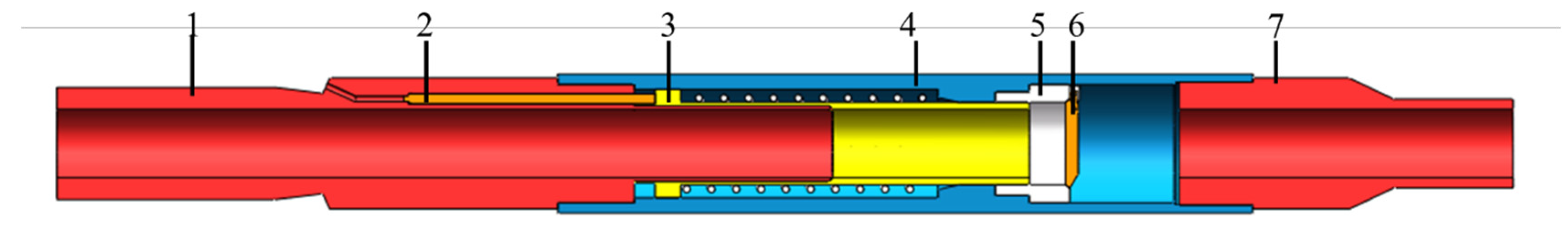
3.1. Building Simulation Models

The simulation analysis of the mechanical behavior of the downhole safety valve is mainly to analyze the stress relationship and distribution law of each component under different loads in the process of downhole operation. In the simulation calculation process, in order to more accurately carry out the effective load transfer between the various components of the downhole safety valve and obtain the reliable stress distribution of each component [16,17]. In order to better match the simulation results with the actual results, full-size, 3D, solid modeling is adopted. The overall model is shown in Figure 3, which mainly includes the upper connector, lower connector, connecting cylinder, center tube, valve plate, valve seat, and plunger.
Considering the difficulty and accuracy of the simulation calculation, some parts of the downhole safety valve will be simplified accordingly. When setting the boundary conditions and constraints, the downhole safety valve working principle will be combined with the simplified parts to make corrections. The downhole safety valve is a homogeneous rotary structure, and most of its components, such as the central tube, upper joint, lower joint, and connecting cylinder, are axisymmetric structures.
The imported 3D model was meshed by the mechanics’ simulation software to control the mesh density and position, and the entity was meshed by default with the corresponding algorithm [18]. The entire downhole safety valve was meshed into tetrahedral cells and hexahedral cells. The specific meshing is shown in Figure 4. The material performance parameters obtained according to the MTS mechanical testing machine are shown in Figure 5 and Table 1. MTS data acquisition system and mechanical testing machine can collect and record the data in real time. The system can collect and test the mechanical properties of samples, such as strength, stiffness and toughness. This allows for a more comprehensive understanding of the properties of materials and provides support for engineering design and control applications. The material performance parameters of downhole safety valve are shown in Table 2.

3.2. Ultimate Load Analysis

The analysis of the simulation results of key components of the downhole safety valve mainly focuses on the upper joint, connecting cylinder, lower joint, and other components. Based on the finite element numerical simulation results of the downhole safety valve system under ultimate load, the mechanical distribution law of the downhole safety valve system under ultimate load is analyzed [19]. The ultimate loading state of the key components of the downhole safety valve is determined, and the calculation basis is provided for the study of the performance envelope curve of the downhole safety valve. Considering the strength calibration of the connection threads of the safety valve body, 1.8 × 10⁶ N (tensile load of the connection threads) was, therefore, determined to calibrate the strength of the safety valve body. Binding constraints were placed on the upper joint, lower joint, valve seat and connection barrel to simulate their connection threads, and frictional constraints were placed on the central tube and upper joint, connection barrel, valve seat, and valve plate, and on the connection rod and valve seat. Setting steps in the simulation software to solve the limit load of downhole safety valve under the condition of less than or equal to yield strength under single load. Under the combined load, the limit load is applied by setting and controlling one of the quantities so that it remains unchanged. The other variable is solved by assignment control to obtain the limit load.
In order to analyze the von Mises stress distribution inside the downhole safety valve under ultimate load, a path was set up axially along the central axis, starting at point A and ending at point B. The distribution pattern of von Mises stress along path AB was obtained.

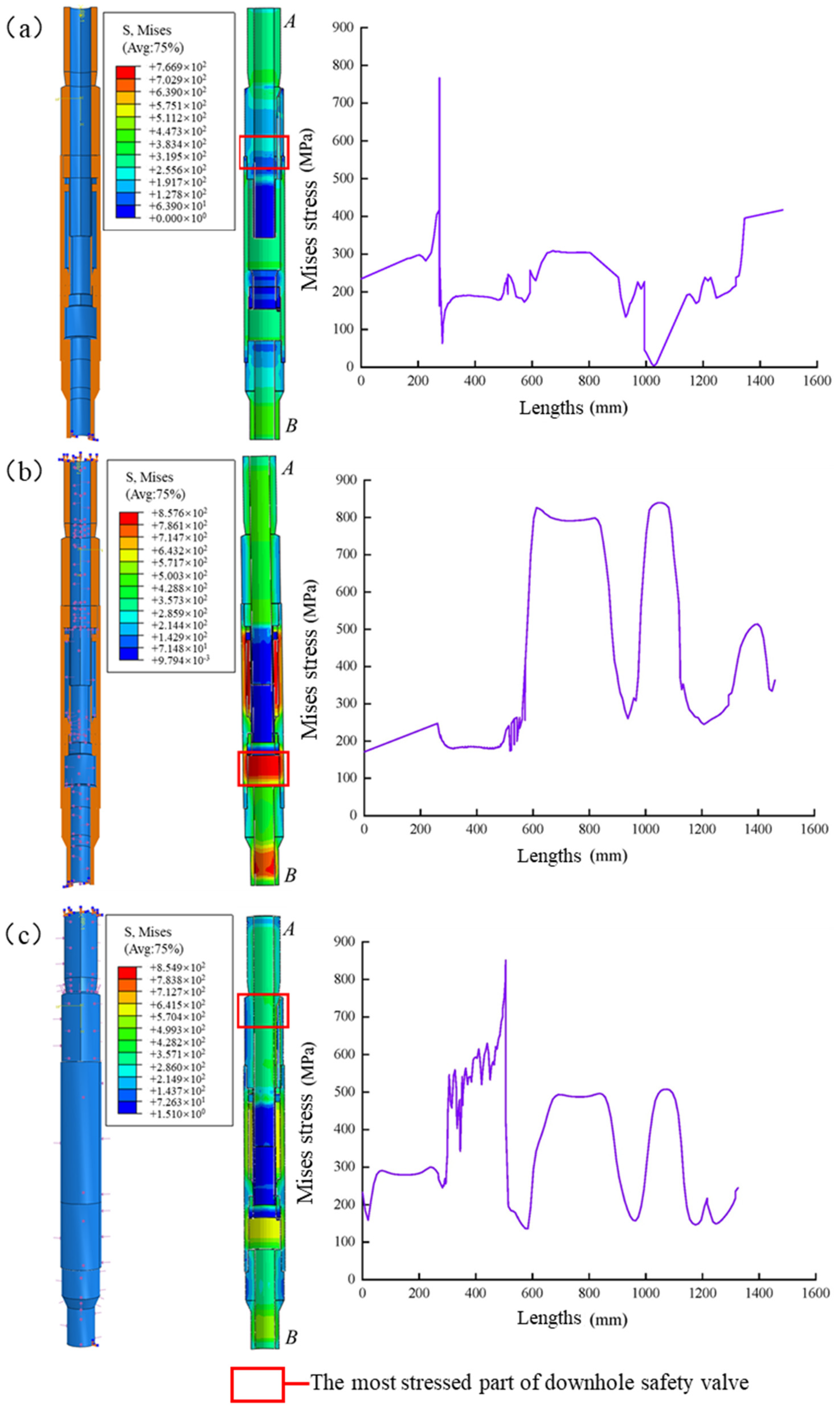
3.2.1. Individual Load Analysis

According to the load setting of the whole set of safety valve simulations, the boundary conditions under tensile or compressive load are determined as fixed constraints at the lower end of the lower joint and coupling constraint at the upper end of the upper joint. Because the yield strength of threads of the downhole safety valve is less than that of downhole safety valve body, the simulation of the downhole safety valve adopts tension and pressure resistance of threads. The tensile load is set to 1.08 × 10⁶ N, and the compression load is set to 1.08 × 10⁶ N. The boundary conditions under internal pressure or external pressure are fixed constraints at the upper and lower joints. The internal pressure is set to 209 MPa, and the external pressure is set to 144 MPa.
When an axial tensile or compressive load of 1.08 × 10⁶ N is applied, the maximum von Mises stress in the body of the safety valve is 766.9 MPa, which occurs at the threaded connection. As shown in Figure 6a, the von Mises stress is much less than the material tensile strength of 861.875 MPa, which indicates that the body of the safety valve meets the ultimate load requirements. When the internal pressure of 209 MPa is applied, the maximum von Mises stress in the body of the safety valve is 857.6 MPa, which occurs at the part of the valve plate cavity that is inside the connection barrel and is subjected to oil and gas pressure. As shown in Figure 6b, at this point, the von Mises stress reaches the yield strength of the material, and the safety valve connection barrel fails. When external pressure of 144 MPa is applied, the maximum von Mises stress in the body of the safety valve is 854.6 MPa, which occurs at the hydraulic passage of the upper joint. As shown in Figure 6c, at this point, the von Mises stress reaches the yield strength of the material, and the upper joint of the safety valve fails. Therefore, considering the tensile strength of the safety valve connection thread, the ultimate tensile load and ultimate compressive load of the safety valve were determined to be 1.08 × 10⁶ N, with an ultimate internal pressure of 209 MPa and an ultimate external pressure of 144 MPa.

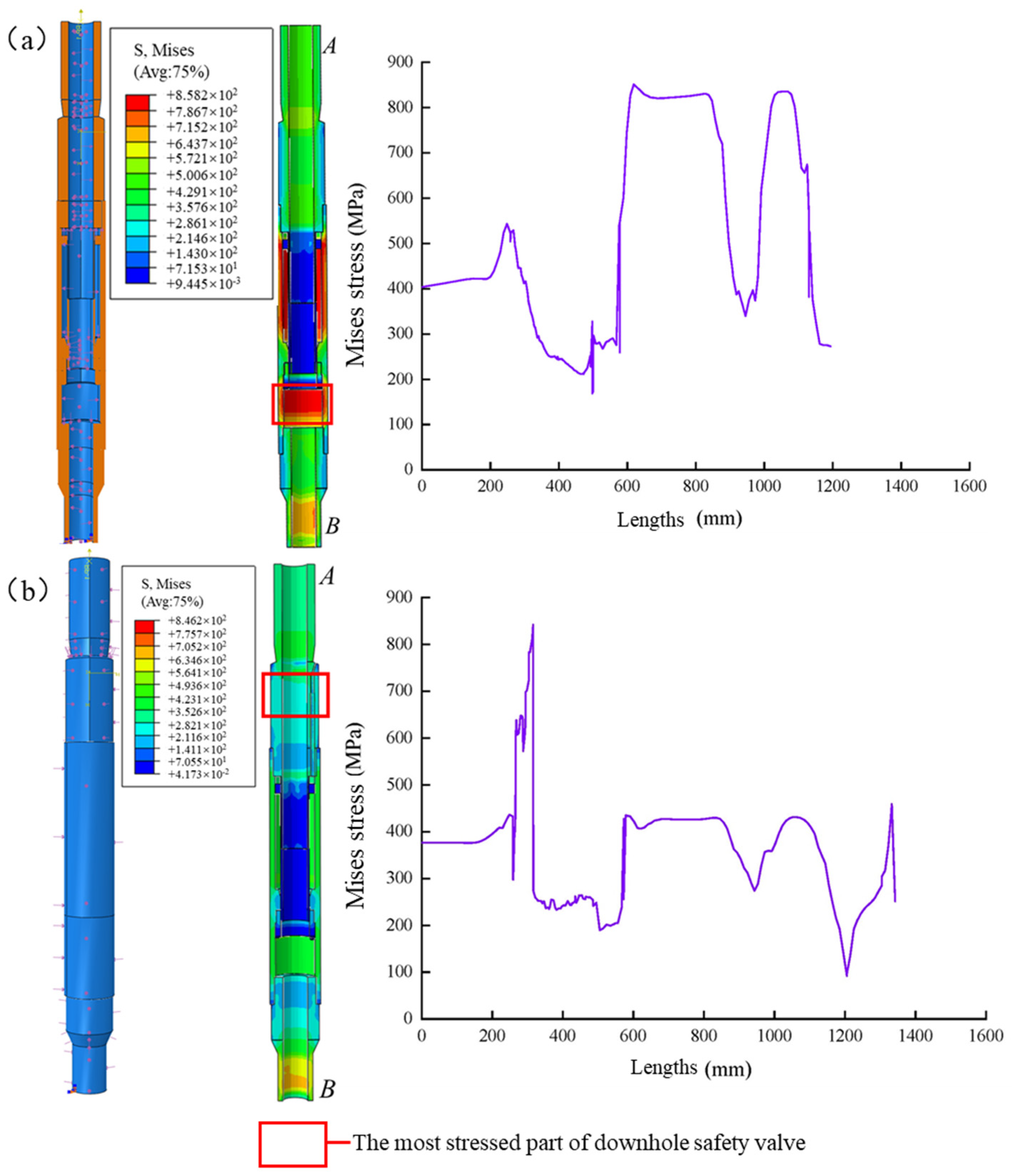
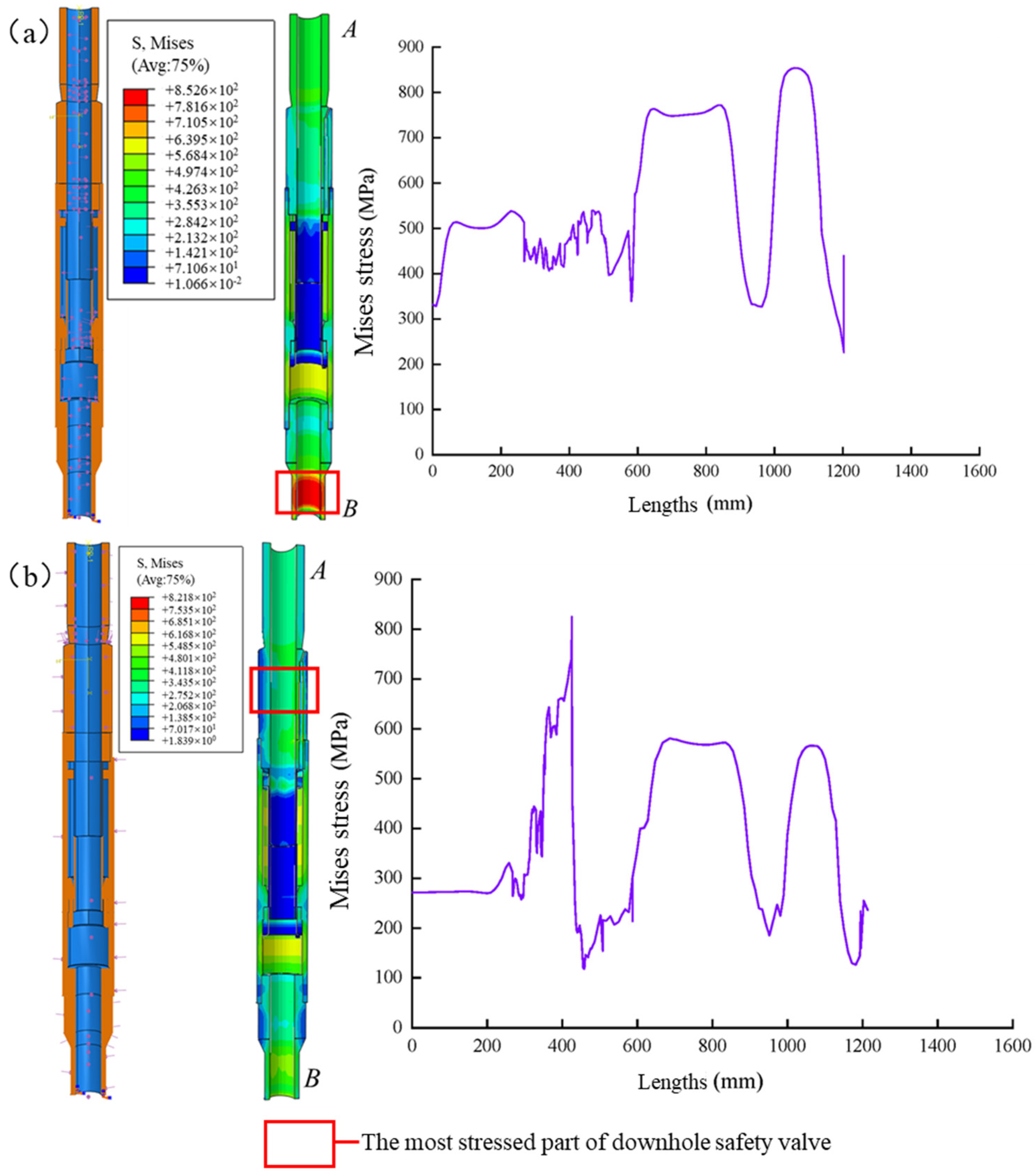
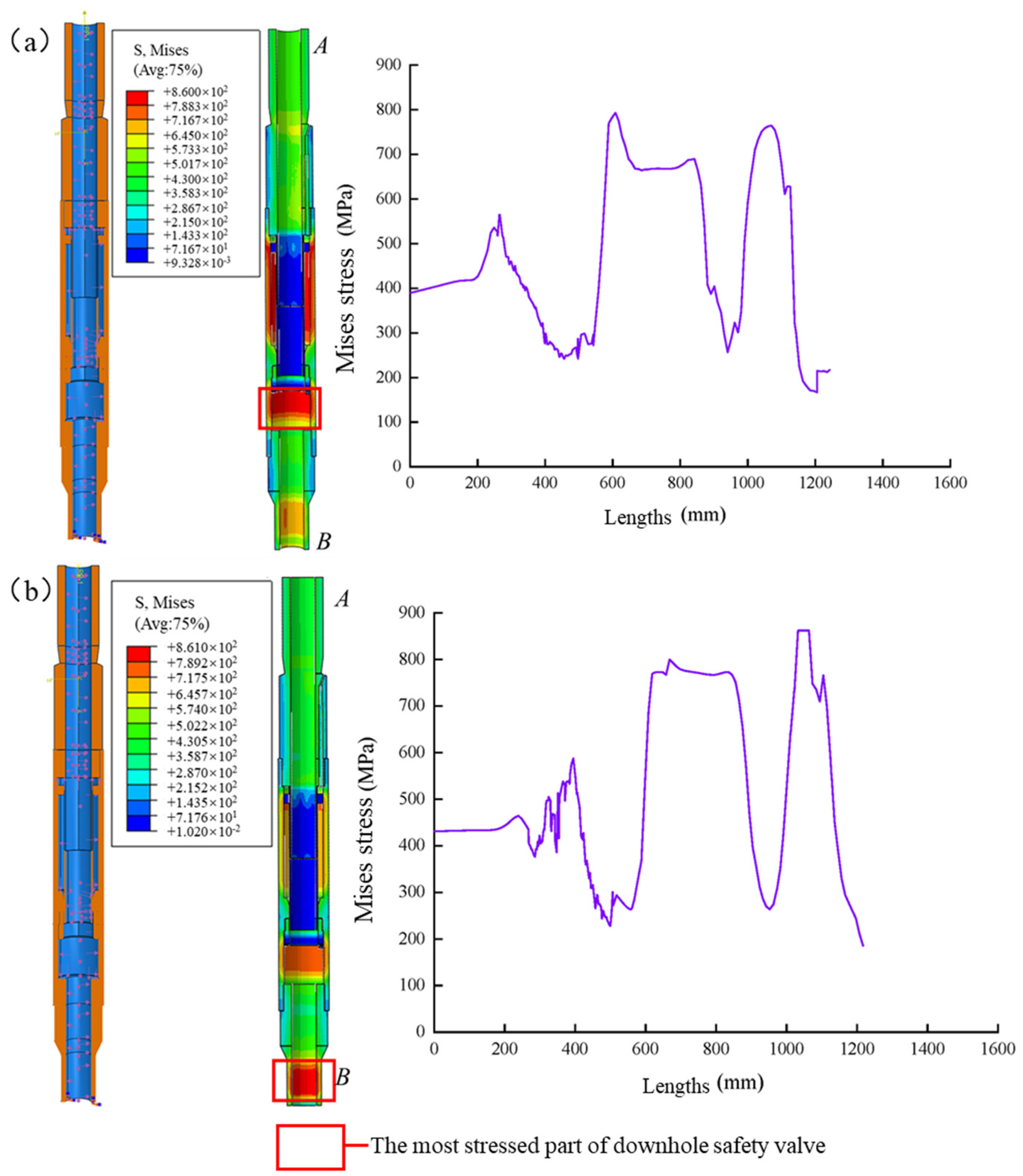
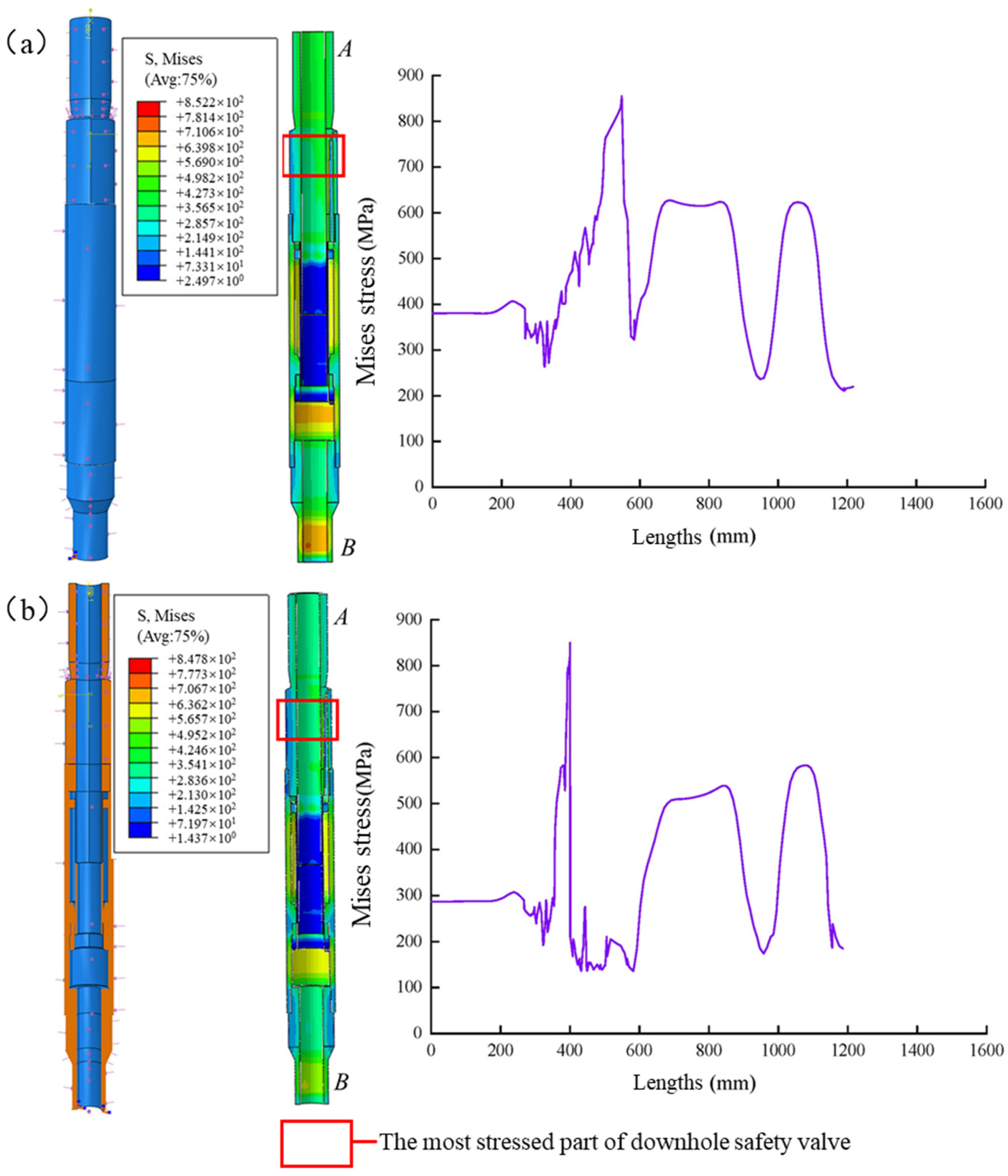
3.2.2. Combined Load Analysis

(1)
Tensile load (ultimate load) + internal pressure/external pressure
The tensile load is 1.08 × 10⁶ N in the ultimate load state. The boundary conditions for the limit load analysis of the downhole safety valve under internal or external pressure are fixed constraints on the lower joint end face and coupling constraints on the upper-end face. A total of 209 MPa is applied under internal pressure, and 46 MPa is applied under external pressure.
At an ultimate tensile load of 1.08 × 10⁶ N and an internal pressure of 209 MPa, the maximum von Mises stress in the body of the safety valve is 858.2 MPa, which occurs at the valve plate cavity inside the connection barrel, which is subjected to oil and gas. As shown in Figure 7a, at this time, the von Mises stress reaches the yield strength of the material, and the connection barrel of the safety valve fails. At an ultimate tensile load of 1.08 × 10⁶ N, the external pressure applied is 46 MPa, and the maximum von Mises stress in the body of the safety valve is 846.2 MPa, which occurs in the upper joint hydraulic passage area. As shown in Figure 7b, at this time, the von Mises stress reaches the yield strength of the material, and the upper joint of the safety valve fails. Therefore, the ultimate tensile load of the safety valve was determined to be 209 MPa for the internal pressure limit load and 46 MPa for the external pressure limit load.
(2)
Compression load (ultimate load) + internal pressure/external pressure
The limit loads of the downhole safety valve are analyzed in terms of internal or external pressure with the compression load in the limit state of 1.08 × 10⁶ N. The boundary conditions are fixed constraints on the lower joint face and coupling constraints on the upper face. The compressive ultimate load is 1.08 × 10⁶ N, 103.4 MPa under internal pressure and 144 MPa under external pressure.
At an ultimate compression load of 1.08 × 10⁶ N and an internal pressure of 103.4 MPa, the maximum von Mises stress in the body of the safety valve is 852.6 MPa, which occurs at the lower end of the lower joint where oil and gas pressure is applied internally. As shown in Figure 8a, at this point, the von Mises stress reaches the yield strength of the material, and the lower joint of the safety valve fails. Under the ultimate compressive load of 1.08 × 10⁶ N, the maximum von Mises stress in the body of the safety valve is 821.8 MPa, which occurs in the hydraulic passage of the upper joint. As shown in Figure 8b, at this point, the von Mises stress reaches the yield strength of the material, and the upper joint of the safety valve fails. Therefore, the ultimate internal pressure of the safety valve under the ultimate compressive load was determined to be 103.4 MPa, and the ultimate external pressure was 144 MPa.
(3)
Internal pressure (ultimate load) + tensile load/compression load
The ultimate load of a downhole safety valve under tensile or compressive loading is analyzed in the limit state with an internal pressure of 209 MPa. The boundary conditions are fixed constraints on the lower joint end face and coupling constraints on the upper-end face. The tensile load is 1.08 × 10⁶ N, and the compressive load is 0.6 × 10⁶ N.
Under the ultimate internal pressure of 209 MPa, the tensile load of 1.08 × 10⁶ N is applied to the upper-end face, and the maximum von Mises stress in the body of the safety valve is 860 MPa, which occurs in the valve plate cavity inside the connection barrel, which is subjected to oil and gas pressure. As shown in Figure 9a, at this point, the von Mises stress reaches the yield strength of the material, and the connection barrel of the safety valve fails. At the ultimate internal pressure of 209 MPa, a compressive load of 0.6 × 10⁶ N is applied to the upper face, and the maximum von Mises stress of 861 MPa is applied to the body of the safety valve, which occurs at the lower end of the lower joint, where it is subjected to oil and gas pressure. As shown in Figure 9b, at this point, the von Mises stress reaches the yield strength of the material, and the lower joint of the safety valve fails. Therefore, the tensile load is determined to be 1.08 × 10⁶ N at the ultimate internal pressure of the safety valve, and the compressive ultimate load is 0.6 × 10⁶ N.
(4)
External pressure (ultimate load) + tensile load/compression load
When the external pressure is 144 MPa in the limit state, analyze the limit state of the downhole safety valve under tensile or compressive load. The boundary conditions are set as fixed constraints on the lower joint end face and coupling constraints on the upper-end face. The tensile load is set to 0.35 × 10⁶ N, and the compressive load is set to 0.49 × 10⁶ N.
At the ultimate external pressure of 144 MPa, the maximum von Mises stress in the body of the safety valve was 852.2 MPa when a tensile load of 0.35 × 10⁶ N was applied to the upper-end face, which occurred in the hydraulic passage of the upper joint. As shown in Figure 10a, at this point, the von Mises stress reached the yield strength of the material, and the upper joint of the safety valve failed. Under the ultimate external pressure of 144 MPa, the compression load of 0.49 × 10⁶ N is applied to the upper-end face, and the maximum von Mises stress in the body of the safety valve is 847.8 MPa, which occurs in the hydraulic passage of the upper joint. As shown in Figure 10b, at this time, the von Mises stress reaches the yield strength of the material, and the upper joint of the safety valve fails. Therefore, the ultimate tensile load of the safety valve under the ultimate external pressure load was determined to be 0.35 × 10⁶ N, and the ultimate compressive load was 0.49 × 10⁶ N.

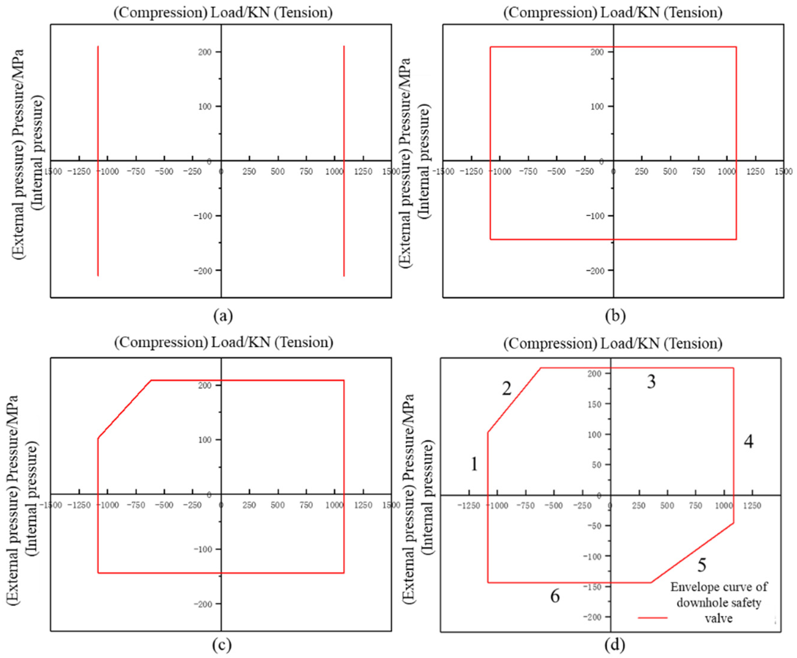
4. Envelope Curve Plotting

The failure modes of the upper joint, lower joint, and connecting barrel were obtained as shown in Table 3. The preliminary FMECA analysis and the failure results obtained through the simulation analysis were in good agreement with both FMECA analysis table results, verifying the correctness of the simulation results under the ultimate load of the downhole safety valve [20]. Through the simulation analysis of the downhole safety valve limit working condition, the downhole safety valve limit load can be determined, as shown in Table 4.
According to the simulation results, different line segments of the downhole safety valve envelope curve represent the bearing limit of different parts under various load combinations, and the intersection point of line segments is the failure point of each part under extreme working conditions. As shown in Figure 11, the performance envelope curve of high-temperature and pressure downhole safety valves can be seen. The inside of the envelope curve belongs to the safe operating area of high-temperature and pressure downhole safety valves, and the outside of the envelope curve belongs to the unsafe operating area of high-temperature and pressure downhole safety valves.
When the tensile load or compressive load reaches 1.08 × 10⁶ N, the threaded connection failure of the upper and lower joints of the downhole safety valve occurs, and the bearing capacity curve is drawn as shown in Figure 11a. When the internal pressure reaches 209 MPa, the valve plate cavity of the downhole safety valve connection cylinder fails; when the external pressure reaches 144 MPa, the hydraulic channel of the upper joint of the downhole safety valve fails, and its bearing capacity curve is drawn as shown in Figure 11b. When the compressive load reaches 1.08 × 10⁶ N and the internal pressure reaches 103.4 MPa, the lower joint body of the downhole safety valve will fail. When the internal pressure reaches 209 MPa and the tensile load reaches 0.62 × 10⁶ N, the downhole safety valve will fail at the lower joint body. Its bearing capacity curve is shown in Figure 11c. When the tensile load reaches 1.08 × 10⁶ N and the external pressure reaches 46 MPa, the hydraulic channel of the upper joint of the downhole safety valve will fail. When the external pressure reaches 144 MPa and the tensile load reaches 0.35 × 10⁶ N, the hydraulic channel of the upper joint will appear in the downhole safety valve. An illustration of its bearing capacity curve is shown in Figure 11d.

5. Conclusions

Based on the principle of drawing the performance envelope curve of the downhole safety valve, the mechanical performance of the downhole safety valve was simulated by numerical simulation. Through the simulation results, the mechanical distribution law of the downhole safety valve under limiting load was carried out. Finally, this study determined the limit-bearing state of the key components of the downhole safety valve and drew the performance envelope curve of the downhole safety valve, from which could be drawn the following conclusions.
Using full-size, 3D solid modeling allows for a more accurate representation of the physical structure, enabling better simulation and analysis of complex engineering problems. It provides a comprehensive understanding of the behavior of the system under different loading conditions, ensuring reliable results and precise predictions. Additionally, full-size 3D solid modeling facilitates effective visualization and communication of the analysis findings to stakeholders, promoting better decision-making in engineering design and optimization processes.
Based on the field operation conditions of the downhole safety valve, it has been determined that the maximum tensile or compressive load is 1.08 × 10⁶ N, while the limits for internal and external pressures are 209 MPa and 144 MPa, respectively. These simulation results serve as a crucial foundation for drawing the performance envelope curve of the downhole safety valve.
The performance envelope curve of the downhole safety valve is a graphical representation of the relationship between the failure forms of the valve and their operating conditions. Which helps demonstrate the limits and capabilities of the safety valve during practical operations, providing insights into potential failure modes and allowing for effective troubleshooting and preventive measures. The theoretical calculation idea involves determining critical operating parameters, such as pressure, that can lead to valve failure. This theoretical foundation applies not only to the study of downhole safety valves but also to other downhole tools used in the oil and gas industry. Understanding the performance limitations and failure modes of these tools is crucial for ensuring efficient and safe operations.

Author Contributions

G.Y.: Conceptualization, Methodology, Writing—original draft. Y.W.: Writing, Editing, Experimental study. Y.F.: Methodology, Formal analysis, Resources. R.M.: Writing, Experimental study. K.N.: Supervision, Funding acquisition. Y.T.: Data curation, Supervision, Resources, Data acquisition. All authors have read and agreed to the published version of the manuscript.

Funding

This research was funded by [development of sulfur-resistant downhole safety valve and packer at 200 °C/105 MPa] grant number [2021ZG11] and the APC was funded by [the major scientific research/field test project of key core technologies of CNPC].

Data Availability Statement

Data is unavailable due to privacy or ethical restrictions.

Conflicts of Interest

We declare that we do not have any commercial or associative interest that represents a conflict of interest in connection with the work submitted.

References

  1. Colombo, D.; Lima, G.B.A.; Pereira, D.R.; Papa, J.P. Regression-based finite element machines for reliability modeling of the downhole safety valves. Reliab. Eng. Syst. Saf. 2020, 198, 106894. [Google Scholar] [CrossRef]
  2. Louzada, F.; Cuminato, J.A.; Rodriguez, O.M.H.; Tomazella, V.L.; Milani, E.A.; Ferreira, P.H.; Ramos, P.L.; Bochio, G.; Perissini, I.C.; Junior, O.A.G.; et al. Incorporation of Frailties Into a Non-Proportional Hazard Regression Model and Its Diagnostics for Reliability Modeling of the downhole safety valves. IEEE Access 2020, 8, 219757–219774. [Google Scholar] [CrossRef]
  3. Gala, D.M.; Menard, B.; Nas, S.; Offner, M. Enhancing Well Safety and Economics with Downhole-lsolation-Valve System. J. Pet. Technol. 2010, 24, 26–27. [Google Scholar]
  4. Qian, F.; Hu, M. Numerical simulation of leakage flow field and acoustic characteristics for safety valve. MATEC Web Conf. 2021, 336, 01007. [Google Scholar] [CrossRef]
  5. Lu, D.; Fu, Q.; Li, Y. Finite element method of instantaneous impact performance of the downhole safety valve plate. Mech. Eng. 2022, 376, 35–38. [Google Scholar]
  6. Luo, J.; Wang, X. Mechanical properties of the downhole safety valve. Pet. Mine Mach. 2020, 49, 36–39. [Google Scholar]
  7. Wang, H. Commonly used downhole safety valve structure in Sheng li offshore oilfield. J. Shengli Oilfield Staff Univ. 2009, 23, 59–61. [Google Scholar]
  8. Gao, W.; Jia, B.; Zhang, A. Packer performance envelope curve. Oil Gas Well Test. 2017, 26, 31–33. [Google Scholar]
  9. Chan, C.L.; Ting, K.L. Curvature theory on contact and transfer characteristics of enveloping curves. J. Mech. Robot. 2020, 12, 011018. [Google Scholar] [CrossRef]
  10. San Cristóbal, J.R. The S-curve envelope as a tool for monitoring and control of projects. Procedia Comput. Sci. 2017, 121, 756–761. [Google Scholar] [CrossRef]
  11. Chaves, L.G.; Studart, T.M.D.C.; Campos, J.N.B.; Souza, F.A.D. Regional envelope curves for the state of Ceara: A tool for verification of hydrological dam safety. RBRH-Rev. Bras. Recur. Hidr. 2017, 22, 10–14. [Google Scholar] [CrossRef]
  12. Li, J.; Tudor, R.; Ginzburg, L. Evaluation and Prediction of the Performance of Positive Displacement Motor (PDM). J. Can. Pet. Technol. 2001, 40, 48–53. [Google Scholar] [CrossRef]
  13. Zhu, X.; Zhou, W.; Lei, Y. A Nonlinear Dynamic Model for Characterizing the Downhole Motions of the Sidetracking Tool in a Multilateral Well. Energies 2023, 16, 588. [Google Scholar] [CrossRef]
  14. Liu, L.; Wang, Y.; Zhang, K.; Kong, L. Uneven wear behavior of downhole tool clearance material under slurry erosion. Alex. Eng. J. 2023, 73, 47–68. [Google Scholar] [CrossRef]
  15. Zang, C.; Jiang, H.; Lu, Z.; Peng, X.; Wang, J.; Lian, Z. Study on the Galvanic Corrosion between 13Cr Alloy Tubing and Downhole Tools of 9Cr and P110: Experimental Investigation and Numerical Simulation. Coatings 2023, 13, 861. [Google Scholar] [CrossRef]
  16. Lan, W.; Peng, J.; Ma, Y. Numerical Simulation of Distributed Heat Storage System for Logging Tools in High-temperature Downhole. K. Cheng Je Wu Li Hsueh Pao/J. Eng. Thermophys. 2021, 42, 2361–2366. [Google Scholar]
  17. Liu, L.; Yu, S.; Liu, E.; Zhu, G.; Li, Q.; Xiong, W.; Wang, B.; Yang, X. Enhanced Mechanical and Degradation Properties of Hollow Glass Microspheres/Mg Matrix Composites by Incorporating Copper Power for Degradable Downhole Tool Applications. Adv. Eng. Mater. 2021, 23, 2100615. [Google Scholar] [CrossRef]
  18. Zhang, B.; Ju, S.; Liu, C.; Ma, Y.; Chen, H.; Fan, L. Research on high-temperature mechanical properties of wellhead and downhole tool steel in offshore multi-round thermal recovery. High Temp. Mater. Process. 2021, 40, 325–336. [Google Scholar] [CrossRef]
  19. Ren, L.; Tang, D.; Zhao, J.; Li, M.; Gan, W. Optimizing the structural parameters of downhole vortex tool in gas well using a genetic algorithm. J. Pet. Sci. Eng. 2021, 200, 108357. [Google Scholar] [CrossRef]
  20. Zhang, Z.; Liao, R.; Liu, J.; Ma, J. Mechanism Study and Geometric Parameter Optimization of the Vortex Downhole Tool. Int. J. Fluid Mach. Syst. 2019, 12, 332–344. [Google Scholar] [CrossRef]
Figure 1. Theoretical envelope curve of the downhole safety valve.
Processes 11 02525 g001
Figure 2. Schematic drawing of the downhole safety valve envelope curve.
Processes 11 02525 g002
Figure 3. Schematic diagram of the underground safety valve structure. 1—Upper joint; 2—Plunger; 3—Central tube; 4—Connecting cylinder; 5—Valve seat; 6—Valve plate; 7—Lower joint.
Processes 11 02525 g003
Figure 4. (a) Simulation model diagram (b) Meshing.
Processes 11 02525 g004
Figure 5. MTS mechanical testing machine.
Processes 11 02525 g005
Figure 6. Safety valve restraint and loading diagram under different loads, stress profile cloud, and distribution pattern of von Mises stress along path AB (a) Tensile load or Compression load (b) Internal pressure (c) External pressure.
Processes 11 02525 g006
Figure 7. Safety valve restraint and loading diagram under different loads, stress profile cloud, and distribution pattern of von Mises stress along path AB (a) Tensile load (ultimate load) + internal pressure (b) Tensile load (ultimate load) + external pressure.
Processes 11 02525 g007
Figure 8. Safety valve restraint and loading diagram under different loads, stress profile cloud, and distribution pattern of von Mises stress along path AB (a) Compression load (ultimate load) + internal pressure (b) Compression load (ultimate load) + external pressure.
Processes 11 02525 g008
Figure 9. Safety valve restraint and loading diagram under different loads, stress profile cloud, and distribution pattern of von Mises stress along path AB (a) Internal pressure (ultimate load) + tensile load (b) Internal pressure (ultimate load) + compressive load.
Processes 11 02525 g009
Figure 10. Safety valve restraint and loading diagram under different loads, stress profile cloud, and distribution pattern of von Mises stress along path AB (a) External pressure (ultimate load) + tensile load (b) External pressure (ultimate load) + compressive load.
Processes 11 02525 g010
Figure 11. Envelope curve plotting (a) Limit load curve under tensile or compressive load (b) Limit load curve under external or internal pressure load (c) Limit load curve under combined internal pressure and tensile or compressive load (d) Limit load curve under combined tensile and external pressure load. 1: Failure of threaded connection; 2: Lower joint body failure; 3: Failure of valve plate cavity of connecting cylinder; 4: Failure of threaded connection; 5: Failure of hydraulic channel of upper joint; 6: Upper Joint Hydraulic Channel Failure.
Processes 11 02525 g011
Table 1. MTS mechanical testing machine basic parameters.
Product ModelSpecificationMaximum Test Speed (mm/min)Minimum Test Speed (mm/min)Weight (Kg)
E45.5056 × 105 N2540.0013500
Table 2. Material performance parameters.
Type of MaterialYoung’s Modulus/MPaPoisson’s RatioYield Strength/MPaFriction Coefficient
Alloy 718165,0000.3861.8750.05
Table 3. Downhole safety valve FMECA analysis.
NameFailure ModesCause of FailureSeverity RatingProbability RatingRisk Assessment
Upper connectorDownhole safety valve disconnected from upper tubingSubstandard mechanical properties or loads exceeding the permissible stress of the jointClass IIE15
Connection failureDeformation due to failure of the threaded teeth or misclasping due to excessive fastening speedClass IVD19
Connection barrelDisconnectionSubstandard mechanical properties or loads exceeding the required stress of the jointClass IE12
Connection failureDeformation due to failure of the threaded teeth or misclasping due to excessive fastening speedClass IIIE17
Lower connectorDisconnectionSubstandard mechanical properties or loads exceeding the permissible stress of the jointClass IE12
Connection failureBecause the speed of fastening is too fast, the striated teeth fail, or the wrong fastening leads to deformationClass IIIE17
Table 4. Limit load of the downhole safety valve (the meaning of symbol “/” is no such combined load form).
LoadTensile LoadCompressive LoadInternal PressureExternal Pressure
Tensile load1.08 × 106 N
(Thread failure)
/1.08 × 106 N, 209 MPa
(Failure of lower joint body)
1.08 × 10⁶ N, 46 MPa
(Failure of lower joint body)
Compressive load/1.08 × 106 N
(Thread failure)
1.08 × 10⁶ N, 103.4 MPa
(Failure of lower joint body)
1.08 × 10⁶ N, 144 MPa
(Upper Joint Hydraulic Channel Failure)
Internal pressure209 MPa, 1.08 × 10⁶ N209 MPa, 0.62 × 10⁶ N
(Failure of lower joint body)
209 MPa
(Failure of lower joint body)
/
External pressure209 MPa, 0.35 × 10⁶ N
(Failure of lower joint body)
144 MPa, 1.08 × 10⁶ N
(Upper Joint Hydraulic Channel Failure)
/144 MPa
(Upper Joint Hydraulic Channel Failure)
Disclaimer/Publisher’s Note: The statements, opinions and data contained in all publications are solely those of the individual author(s) and contributor(s) and not of MDPI and/or the editor(s). MDPI and/or the editor(s) disclaim responsibility for any injury to people or property resulting from any ideas, methods, instructions or products referred to in the content.

