Article

Microparticles’ Lateral Oscillation Motion in Serpentine Micro-Channels without Inertial Lift Effects

1
Frontier Scientific Research Centre for Fluidized Mining of Deep Underground Resources, China University of Mining & Technology, Xuzhou 221116, China
2
State Key Laboratory of Intelligent Construction and Healthy Operation and Maintenance of Deep Underground Engineering, China University of Mining & Technology, Xuzhou 221116, China
3
School of Mechanics & Civil Engineering, China University of Mining & Technology, Xuzhou 221116, China
4
Institute of Combustion and Thermal System, School of Mechanical, Electronic and Control Engineering, Beijing Jiaotong University, Beijing 100044, China
*
Author to whom correspondence should be addressed.
These authors contributed equally to this work.
Processes 2023, 11(8), 2411; https://doi.org/10.3390/pr11082411
Submission received: 31 July 2023 / Revised: 7 August 2023 / Accepted: 8 August 2023 / Published: 10 August 2023
(This article belongs to the Section Particle Processes)

Abstract

:
Micro-particle manipulation, based solely on the Dean drag force, has begun to be advocated for with the goal of lowering the pumping pressure and simplifying the complexity of the coupling effects of the inertial lift force and the Dean drag force, thus reducing the difficulty of theoretically predicting particle motion. We employed the CFD-DEM two-way coupling method in this work to quantitatively study the lateral (z in axis) motion of particles (7–10 μ m ), in square or half-circle segment serpentine microchannels, that was only reliant on Dean drag with the blockage ratio d D h = 0.04 (the inertial lift effects show at d D h > 0.07 ). In the square-segment serpentine channel, under the conditions of single-side-wall sheath flow and sedimentation, we discovered that the particles exhibit a twist-type lateral trajectory around each turn, with the larger particles always twisting in the opposite direction of the smaller particles, as a result of the four-grid-pattern distribution of the lateral velocity values at each turn. The large and small particles are separated at the channel’s exit at R e = 56.7, De = 17.8, indicating the likelihood of separation only due to the Dean drag. This separation efficiency decreases as R e and De decreases. The lateral position and velocity values of the particles oscillate, as time passes, due to the twist trajectory, with the oscillation amplitude increasing as R e or De decreases and deflecting toward the inner side of z. In the cases of the two-side-wall-symmetric sheath flow, the particles exhibit only a little lateral deflection, and particle separation is not achieved. The deflection of the oscillation is uncertain and does not change regularly with any physical quantity.

1. Introduction

Microfluidics technology has been widely employed in chemistry, biology, and medicine to analyze or manipulate bio-particles. For example, patients’ peripheral blood has been found to contain the circulating tumor cells (CTCs) that are discharged from primary or metastatic malignancies [1,2]. As a result, detecting or isolating tumor cells from patients’ blood is required for cancer detection, and microfluidics is an excellent solution [3,4,5]. Dielectrophoresis (DEP) [6,7,8], magnetophoresis (MP) [9], and acoustophoresis (AP) [10,11] are active techniques, employed in microfluidic devices, that are classified depending on the external forces imparted to the particles or cells. There are also passive microfluidics, such as hydrodynamic microchannels [12,13,14,15,16,17,18,19,20,21,22,23], in which particle motion is solely determined by hydrodynamic forces such as inertial lift force, drag force owing to secondary flow, and centrifugal force. The benefits of passive hydrodynamic microfluidics are high throughput, cheap cost, and simple design. Due to the various sizes of the particles, they are focused on different equilibrium locations. CTCs apparently appear to be larger in blood than other blood cells, such as red and white cells, making isolation from other cells within the blood achievable.
Segré and Silberberg were the first to discover particle lateral motion across streamlines in a macroscale cylindrical tube, and the inertial lift force focuses the particles into an annulus [24,25]. The focusing process is the result of two effects: the lift toward the wall, caused by the shear gradient and caused by the curvature of the Poiseuille velocity profile; the lift that pulls particles away from the wall. The inertial lift force has been widely used in microchannels throughout the last decade to achieve particle focusing [12,26], separation [12,15,27,28], ordering [12], and filtration [15,29,30,31,32,33]. Microchannels, unlike circular tubes, typically feature square or rectangular cross-sections due to their production method. Particles are concentrated in a more sophisticated manner, resulting in more equilibrium positions. The square channel has four or eight equilibrium positions depending on the blockage ratio and the Reynolds number [29,33,34], whereas the rectangle channel has two equilibrium locations near the long face wall [35,36,37,38,39,40,41]. Di Carlo et al. originally explored the intricate scaling of the inertial force, which is F L ρ f U m a x 2 d 3 / h ( d is the particle diameter, ρ f is the fluid density, U m a x is the maximum velocity of the flow, and h is the height of the channel) near the channel center and F L ρ f U m a x 2 d 6 / h 3 near the channel wall [37].
Curved channels, as compared to straight channels, were found to reduce the length of the channel necessary to focus particles [12,31]. Di Carlo et al. investigated particle ordering in a square-cross-sectioned asymmetric serpentine micro-channel when particle size and Reynolds number were varied [12]. To meet mass conservation, the Dean flow, which is characterized by two counter-rotating vortices, points to the outer wall at the mid-plane but to the inner wall at the top and bottom. The Stokes drag force drives the particles outward on average. However, the particles are focused down the channel into a single stream since the outward direction changes at each serpentine bend. Di Carlo observed that, when paired with the inertial lift force and the Dean drag force, the curved channel collapses the four equilibrium points into a single particle stream. Based on their findings, they produced a phase diagram depicting particle focusing and defocusing with the Dean number D e as the x-axis and the blockage ratio d D h ( D h the hydraulic radius) as the y-axis. Focusing is achieved when d D h > 0.07 as well as D e > 3 . This discovery shows that particle size separation might be achieved. In another paper [42], their group measured the mobility of particles that were initially positioned at the inner and outer walls of the curved channel. They discovered that particles initially situated near the channel’s outer wall migrate toward the inner wall around a channel turn, which contradicts the main effects caused by the outer-wall-pointed centrifugal force. The motion of these particles follows the Dean flow stream and changes the focus plane around the turn, rather than being dominated by inertial lift or centrifugal force. When compared to particles that start at the inner wall and migrate to the outer wall, the lateral velocity of these particles increases with the average velocity of the channel, albeit substantially less, and this increase is only detected above a certain threshold of the average velocity. This implies that lateral motion is determined by the initial positions of the particles. The competition between the inertial lift force and the Dean drag force is represented using a ratio R f = 2 r d 2 D h 3 f ( r is the curvature radius, and f is a dimensionless value dependent on the channel Reynolds number and the dimensions of the channel). The lateral manipulation of particles is commonly conducted at R f ~ 1 . Applying this, Lee et al. successfully separated tumor cells and red cells in blood using a contraction–expansion array microchannel device [43]. The particle’s equilibrium locations are defined by both the inertial lift force and the Dean drag force. Larger particles are influenced by the inertial lift force more than the Dean drag force (higher R f as a result of larger particle size), so tumor cells with larger sizes attain an equilibrium position closer to the concave–convex side wall. In contrast, the Dean drag flow dominates the lateral motion of red cells that are smaller in size and closer to a flat side wall. To focus the particles, Oakey et al. used a rectangular-cross microfluidic device with an asymmetrical curve component before the straight part [22]. The particles in the asymmetrical curve segment of the upstream flow are focused to two vertical equilibrium heights. They are focused to a single stream after being relayed to the straight part, as the straight part channel tends to suppress the two vertical equilibrium positions.
The Dean flow alters the inertial lift force’s equilibrium positions, making it more challenging to anticipate particle lateral motion and design practical microfluidic systems. Additionally, the inertial lift force is only relevant for larger blockage ratios d D h > 0.07 [12], necessitating a narrow channel and, thus, raising pumping resistance. To get around these restrictions, Zhang et al. developed a novel idea and employed a large-square-cross-sectioned serpentine microchannel [44]. This allowed them to focus particles without the aid of inertial lift and solely by employing secondary flow and centrifugal force on the particles.
So far, since measurements in microfluidics studies are always made in the primary flow direction, the complexity of the process underlying the lateral motion of particles is unclear as a result of the absence of lateral flow observation. Numerical simulations would be able to get around this restriction, although little study has been done in this area. To investigate the lateral trajectory and rotation of particles in a contraction–expansion channel, Jiang et al. used a lattice–Boltzmann method (LBM)-immersed boundary method (IBM) model [45]. The particles’ volume effects and, thus, the effects of the inertial lift force could both be precisely accounted for using the IBM technique. According to the modeling results, the Dean secondary flow is crucial for concentrating particles of various sizes in certain locations.
In this study, we apply Zhang’s idea and manipulate the particles, in serpentine channels with rectangular cross-sections, solely using the Dean secondary flow. We employed an Eulerian–Lagrangian point-particle simulation approach with a two-way coupling method, taking into account the particle contact interactions, to examine the lateral motion of the particles. In reality, the force that particles exert on the fluid can be completely eliminated, and the double coupling can be reduced to a single-way coupling only at extremely low solid fractions of 10 6 [46]. The simulations are run in a square-segment serpentine channel and a half-circle segment serpentine channel, respectively. The impacts of flow rate, particle releasing position, and fluid rheology are systematically investigated.

2. Numerical Simulation Method

2.1. Calculation Scheme

By combining Fluent19.0 and EDEM2018 softwares, computational fluid dynamics-discrete element method (CFD-DEM) is used to model the flow field and particle motion in the serpentine microchannels. The continuous fluid is calculated in an Eulerian coordinate in this Eulerian–Lagrangian system, while the discrete particles are monitored in a Lagrangian framework in accordance with Newton’s second law. The traditional Eulerian–Lagrangian method, in which the mesh size of the continuous phase is set to be four to five times the particle size, was utilized in the current investigation because the particle size is small relative to the channel. Particle–particle and particle–wall interactions are taken into account in CFD-DEM, which is particularly significant in locations close to the channel wall and corners. The following is the CFD-DEM coupling principle: Fluent solves the N-S equations of the fluid phase first; EDEM then calculates the force on the particles exerted by the fluid and updates the positions of the particles using the fluid information in each cell; finally, Fluent calculates the force on the fluid exerted by the particles and updates the fluid information, repeating this cycle until convergence is reached.
Collisions with other particles or the channel wall, as well as interactions between the continuous phases, all contribute to particle motion. The particle size in our computation technique is much smaller than the mesh size of the continuous phase, and the calculation treats the particles as points and uses Newton’s second law, which is decomposed into translational and rotational motion. When calculating the interaction force between the particle and the fluid in this approach, the fluid information is provided by the fluid mesh in which the particle is included. When the particle size exceeds the mesh size of the continuous phase, the fluid force imparted on each particle must be calculated by integrating the particle volume across numerous fluid meshes, such as the body-fitted grid technique [47] or the immersed boundary method (IBM) [48], which are more difficult and incompatible with commercial Fluent19.0 software. The influence from far field, due to disturbance waves, is negligible when the calculation time step is smaller than the diffusion time of the waves [49]. Thus, the motion of a single particle is governed by [50]:
m d U p d t = m g + F p f + F c
I d ω d t = M
where m is the mass of the particle, g is the gravitational acceleration, I is the moment of inertia of the particle, U p is the velocity of the particle, F p f is the interaction force between the particle and the fluid, and F c is the collision contact force between particles or between the particle and the channel wall. Particle–fluid interaction force includes buoyance force, virtual mass force, drag force, pressure gradient force, and lift force. Only the drag force F d , pressure gradient force F p and lift force F l are considered in this study. The virtual mass force, basset force, Magnus force, and the Saffman force [51,52] are neglected in the calculation. The latter two forces are members of the lift force family. We did not include them in the computation and calculated the entire lift force F l independently by using a UDF, as shown below. Therefore,
F p f = F d + F p + F l
F d = C d U f U p / α f
F p = ρ f V p g d U f d t
F l = C l ρ f U m a x d 2 d H 2
where V p is the particle volume, U f is the velocity of the fluid, and U m a x is the maximum value. α f and ρ f are the volume fraction and the density of the fluid, respectively. C d is the drag coefficient, for which the Ergun model is chosen in the current study:
C d = V p 150 1 α f α f μ f d 2 + 1.75 ρ f U f U p d
with d representing the diameter of the particle and μ f representing the viscosity of the fluid. C l is the coefficient of the lift force, which depends on the lateral position and the fluid velocity. We use C l with the method invented by Liu et al., and we obtained C l through fitting the curves in [53], using the polynomial functions for a rectangular-cross-sectioned channel, with an aspect ratio of 2.
Considering the easy deformation of cell particles and their soft mechanical properties, the contact force F c is calculated using the soft ball model, and it is decomposed of tangential component F c t and normal F c n component. The normal contact force is modeled as a dissipation damping coefficient connected, in parallel, with an elastic spring, which is the same as the tangential contact force. The two forces are connected by a friction slider. The resultant contact force [54] between particle i and particle j is:
F c , i j = k n , i j δ n , i j γ n , i j δ ˙ n , i j k t , i j δ t , i j γ t , i j δ ˙ t , i j
where k n , i j and k t , i j are the spring stiffness for the normal and tangential components, respectively. γ n , i j and γ t , i j are the damping coefficients for the normal and tangential directions, respectively. δ n , i j is the normal overlap of the two particles, while δ t , i j is the tangential overlap. The equation of k n , i j [55] is:
k n , i j = 4 3 E e q d e q 2 1 2 δ n , i j 1 2
with E e q representing the equivalent Young’s modulus and d e q representing the equivalent diameter
1 E e q = 1 ν i 2 E i + 1 ν j 2 E j
1 d e q = 1 d i + 1 d j
E i , j is Young’s modulus of the particles. ν i , j is Poisson’s ratio of the particles. The tangential stiffness [56] is:
k t , i j = 8 G e q δ t , i j d e q 2 1 2 δ n , i j 1 2
with G e q representing the equivalent shear modulus
1 G e q = 2 2 + ν i 1 ν i E i + 2 2 + ν j 1 ν j E j
The normal damping coefficient is
γ n , i j = 2 5 6 ln e l n 2 e + π 2 2 3 k n , i j m e q
with m e q representing the equivalent mass
1 m e q = 1 m i + 1 m j
The tangential damping coefficient is
γ t , i j = 2 5 6 ln e l n 2 e + π 2 k t , i j m e q
Young’s modulus E of the particles, representing cells, is taken as 140 kPa [57], and Poisson’s ratio ν is taken as 0.5 [58]. The contact force between particles and the wall follows the same calculation scheme. The Young’s modulus and Poisson’s ratio of the wall are set to match the materials of the microchannels made of poly(dimethylsiloxane) (PDMS) in the real circumstances.
The motion of the continuous fluid phase is described by an incompressible Navier–Stokes (N-S) equation with the volume fraction:
t α f ρ f + · α f ρ f U f = 0 ,
t α f ρ f U f + · α f ρ f U f U f · α f ρ f τ f = P + ρ f g + f p f
f p f is the force exerted on the fluid by particles, which is the opposite of the sum of the force exerted on particles by the fluid in each fluid mesh cell:
f p f = 1 V c e l l k = 1 n C d U f U p + 1 V c e l l k = 1 n V p P
V c e l l is the volume of the fluid mesh cell. n is the number of particles in each cell, and k is the index of the particles. τ f in Equation (18) is the stress tensor of the fluid:
τ f = μ f ρ f U f + U f T 2 3 μ f ρ f · U f I
I is the identity matrix.

2.2. Software Settings and Physical Problem

Figure 1 illustrates the two serpentine microchannel types that were investigated: the square-segment serpentine microchannel and the half-circle-segment serpentine microchannel. Both channels are asymmetrical, with the upper segments measuring 1.5 mm in width compared to the lower segments’ 1 mm. The rectangle cross-sections of both channels measure 0.5 mm in width by 0.25 mm in height. The channels’ entire effective lengths in the main flow direction are 25 mm. The grid study and validation were carried out to investigate the influence of the fluid mesh on the simulation outcomes. It is not true that a finer grid is better because the CFD-DEM computation scheme we utilized in this study treats particles as points, so the continuous phase mesh size must be at least four times greater than the particle size. The calculation will diverge if the fluid mesh is so small that it is near to, or even smaller than, the particle size. However, the fluid mesh size cannot be too large because the quality of the fluid motion calculation is improved when the mesh size is reduced. In conclusion, to balance these two points, after many trials, we discovered that it is possible to achieve good results when the square-serpentine channel has 416,031 nodes and the circular-serpentine channel has 502,496 nodes. The meshing grid was drawn in Gambit16 software. To calculate the velocity of the fluid phase in Fluent, the laminar incompressible flow model was chosen, and no-slip is enforced on the walls. The fluid has a density of 1000 kg/m3 ( ρ f ). Additionally, the particle density was set to ρ p = 1.08 ρ f to imitate cell density [59].
An injection of particles and a uniform fluid velocity define the inlet boundary condition. The fluid’s inlet velocity is set at 3, 5, 7, and 9 cm/s, correspondingly. To counteract the impact of the particles’ initial velocity, the injection speed of the particles from the particle factory is much lower at 0.05 cm/s. The particle sizes follow a Rosin–Rammler distribution, with a mean size of 8.5 μ m , a minimum size of 7 μ m , and a maximum size of 10 μ m . The smaller particles stand in for the red blood cells, and the larger ones stand in for the tumor cells. The number of particles injected per unit time is set so that the volume fraction of the particles in the microchannel is approximately in the range of the other research: 1 × 10 6 particles mL 1 [18,53,60].
The particle injection is configured using a particle factory in EDEM2018 software, which is a two-dimensional shape positioned at the channel’s intake face. We used two types of particle factories in the simulations: one is positioned on the side wall of the inlet (on the left of Figure 1, it is the red thin strip at the inlet of the square channel), and the other is located at the middle z location, which is not represented. The particle factory’s first setting has the effect of imposing a single-side-wall sheath flow to the particles injected randomly from the entrance. The particle factory’s second setting is equal to the effect of imposing a two-side-wall-symmetric sheath flow on the particles injected randomly from the source. This is to investigate the impacts of the sheath flow introduction method. We did not draw a geometry with the sheath flow branch based on the real picture, nor did we simulate the real situation in which the sheath flow interacts with particles injected randomly from the entrance, because this simulation requires a very long channel length to achieve the desired results. This is meant to investigate the impacts of the sheath flow introduction method. As a result, in order to simplify the geometry design and lower the computational cost, we simply replicate the sheath flow by restricting the particles to a specified area at the inlet. In fact, we attempted to do one example using a model that was completely based on the actual situation and discovered that the results were not significantly different from the case in which the sheath flow is mimicked by the particle factory. Consequently, we believe this simplification is appropriate for our simulations. Furthermore, the vertical, narrow strip of particle streams fed from the particle factory accounts for the particle configuration resulting from gravity sedimentation under real-world conditions, with smaller particles positioned above larger ones.

2.3. Non-Newtonian Fluid

The effects of fluid rheology are investigated in this study. Apart from water used as the dilute fluid for the blood, polymer solutions are also used. In the simulations, we used shear thinning poly(ethylene oxide) (PEO, molecular weight 4 × 10 5   g / mol ) solutions of two different concentrations to modify the rheology of the blood sample: one is 0.5% and the other is 2%. PEO is a semi-crystalline polymer with a melting range of 57–73 °C, and the melting temperature of the crystalline region of PEO is centered at 68.81 °C [61]. The elastic lift force F e is illuminated since the particle size is much smaller than the channel size F e = C e d 3 N 1 ( C e is the nondimensional coefficient, and N 1 is the first normal stress difference) [60]. The rheological properties of PEO solutions are referenced in [62] and obey the Cross model:
μ μ μ 0 μ = 1 1 + λ · γ ˙ m
The parameters of the Cross model are listed in Table 1. The viscosity, obeying the Cross model, was written into Fluent through a User Defined Function.

3. Results and Discussion

3.1. Transverse Motion

3.1.1. Square-Segment Serpentine Channel

The flow in curved channels is characterized by two dimensionless numbers: the Reynolds number and the Dean number. The channel Reynolds number, based on the velocity of the fluid in the channel, is R e = 2 U m D h 3 ν [37]. U m is the maximum velocity of the fluid. D h = 2 w h w + h is the hydraulic diameter of the rectangular cross-section of the channel. ν is the kinetic viscosity of the fluid. The Dean number, reflecting the strength of the secondary flow, is defined as D e = R e D h / 2 r . r is the curvature radius of the curved channel. The inertial lift force F L = ρ f U m 2 d 4 D h 2 f c and the Dean drag force F D ~ ρ f U m 2 d D h 2 r , together, determine the preferred lateral position of the particle. f c is the lift coefficient, which is a function of the Reynolds number and the lateral position of the channel. In this study, in order to neglect the effects of the inertial lift, the cross-section of the channel is designed to be much larger than the particle size, so the ratio of these two forces is F L F D ~ 1 δ d D h 3 f c = 6 × 10 5 f c , where δ = D h 2 r is the curvature ratio and f c is in the range of 0.6-0.2. Therefore, the Dean drag force is always predominant compared to the inertial lift force. The focus of this study is the lateral motion of particles under the influence of mere Dean drag.
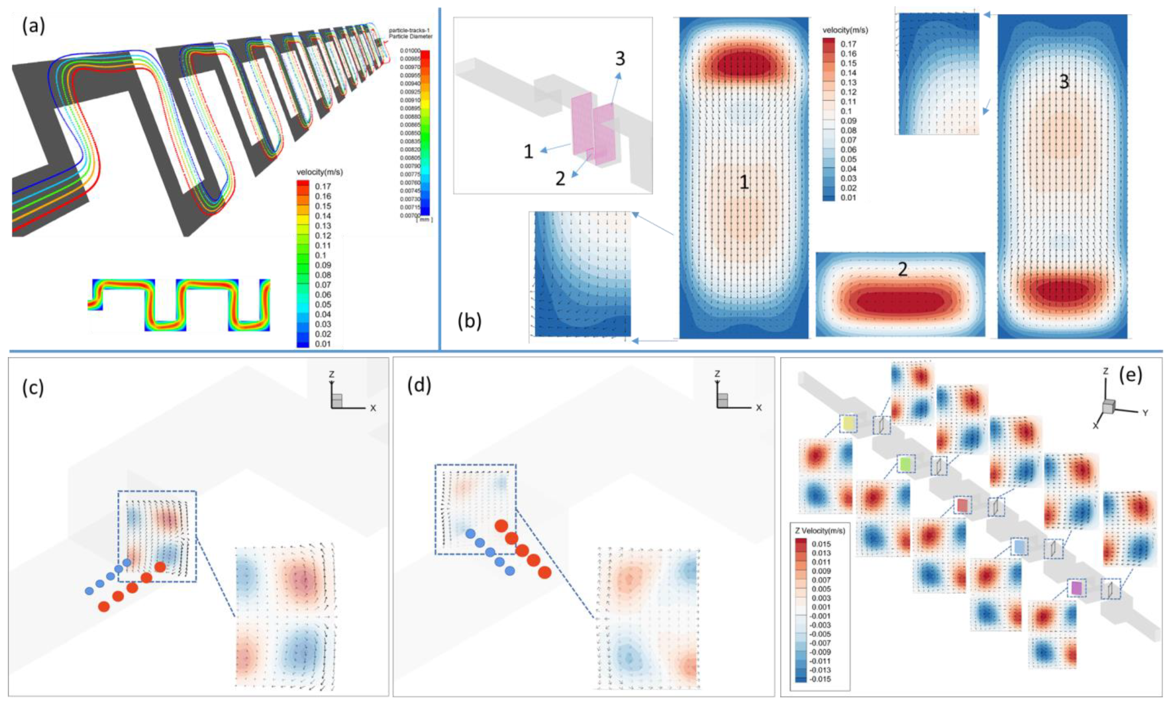
Figure 2a depicts the lateral deflection of particles of various sizes in pure water at a fluid inlet speed of 9 cm/s ( R e = 56.7, De = 17.8) under the single-side-wall sheath flow. The smaller particles (blue) deflect outwards (positive z-direction) when they enter the first turn from the inlet, but the bigger particles (red) deflect inwards. The particles’ deflection in the lateral-z direction on the inclined slice (with the inclination angle of 135 ° ), at this turn, follows the flow of z (Figure 2c). It is worth mentioning that the opposite deflections of large and small particles are connected to their initial positions from the inlet face, with smaller particles initially located close to the channel’s upper wall and larger particles initially located close to the channel’s bottom wall. The z-velocity field at the slice at the first turn, as shown in Figure 2c, has a four-grid-pattern distribution, which means that the sign of z-velocity is the same at the diagonal corners. The smaller particles strike the positive-zone of z-velocity with this configuration of the z-velocity field and the particle injection pattern, whereas the larger particles hit the negative-zone of z-velocity. As a result, smaller and larger particles deflect in opposing directions along the z-axis. Such staggered deflection would not have occurred if the particles of diverse sizes had all been incidents from the inlet-face center, where the z-velocity is null. However, once the particles travel through the turn, they tend to return to the primary upward flow direction and restrain the lateral deflection, resulting in a twist motion around a turn (Figure 2a). Figure 2b (plane 3, viewed in the negative x-direction) depicts the flow field on the vertical y–z plane of the going-up part within a segment. Aside from the higher and lower regions of plane 3, the flow is considerably upward in most places, which suppresses the longitudinal deflections of both small and big particles after they pass the turn, giving birth to the twist. The four-grid-pattern distribution of z-velocity in Figure 2c corresponds to the splitting flow at the top of plane 3 and the converging flow at the bottom.
The four-grid-pattern z-velocity distribution on the slice changes signs at the second turn (compare Figure 2c,d), so the small and large particles deflect in opposite z-directions relative to the first turn, with the smaller particles moving inward and the larger ones moving outward. After passing through this turn, the particles enter the top-horizontal section of the segment and face a pair of splitting Dean vortices that are opposite the pair of converging Dean vortices in the bottom-horizontal section (Figure 2b, plane 2). The smaller particles placed close to the top wall are pushed outward by the slitting Dean vortices, while the bigger particles located close to the bottom wall are drawn inward, which causes a twist in the particle paths once more. Every time the particles travel through a turn, the z-deflection changes the sign, inducing a twisted particle trajectory and causing the smaller and larger particles to always go in the opposing z orientations.
Figure 3a depicts the spatial arrangement of particles of various sizes from the channel’s front view. At early turns, the particles increasingly deflect toward the inner-wall side in the upper horizontal portion of the segment; this is especially true for the larger particles. This is in line with the fluid velocity field (bottom of Figure 2a), where the drag force is imposed and rises with particle size. The particles in the bottom horizontal portion of the segment are tilted upward as a result of the drag force. From Figure 3a, even while the fluid’s velocity distribution varies very little in the later segments compared to the earlier segments (it always remains the same as the one shown in Figure 2a), the particles are getting harder and harder to deflect in directions other than the primary flow direction because they are accelerating (Figure 3b), in the primary-flow direction, downward the flow. A successful size-based separation is achieved at the outflow, as shown in Figure 3e, where the smaller particles are located closer to the top wall of the channel and the bigger particles locate closer to the bottom wall. In a serpentine microchannel, Zhang et al. achieved particle focusing at the outlet [44]. Instead of a random injection, such as in Zhang’s experiments. or a central injection that we will also discuss in the later content, keep in mind the method of particle introduction used in our case, which is under a single-side-wall sheath flow simulated by a vertical, thin strip of particle streams (Figure 2a) injected from the side wall of the inlet face. Therefore, in our situation, the motion of the particles is significantly influenced by the initial position, and it is made more complicated by the secondary flow close to the side wall. At the exit, the placement of particles of various sizes in the z-direction is depicted in Figure 3d. The medium-sized particles are closer to the central axial line, while the largest and smallest particles are closer to the side wall. In actuality, there is a strong correlation between the y and z-positions of the particles. To highlight this relationship, we choose the lower horizontal portion of the final segment (in Figure 3d, the area between the two twists) that is closest to the outlet. The Dean flow (Figure 3c) points outward near the bottom and the outer side wall, where the largest particles (red) are located. As a result, the largest particles have a tendency to gravitate toward the outer wall. In contrast, the Dean flow is pointed toward the center of the z-axis near the top wall, where the smaller particles (blue and green) are located, causing the smaller particles to deflect inward. Yellow medium-sized particles are located close to the middle z and y-positions. The yellow particles do not deflect much in both the z and y-directions, at this point, because the Dean flow is relatively weak.
Figure 4 depicts the findings for a greater viscosity fluid (2% PEO) at a lower flow speed of 3 cm/s. The particle locations at the exit, in the y-direction (Figure 4d), are nearly identical to those at the intake, owing to the fact that the fluid velocity does not deflect in the vertical direction (Figure 4b). Figure 4a shows that the particles deflect little in the lateral direction (z) because the secondary flow at a significantly lower Reynolds number or Dean number (=0.4), as seen in Figure 4c, is much weaker. In comparison to Figure 2b, there is no visible secondary converging or splitting flow in the planes of both the uphill and descending segments. As a result, at the outlet, the particles of different sizes are located at, almost, the same value in the z-direction as the inlet (Figure 4e).
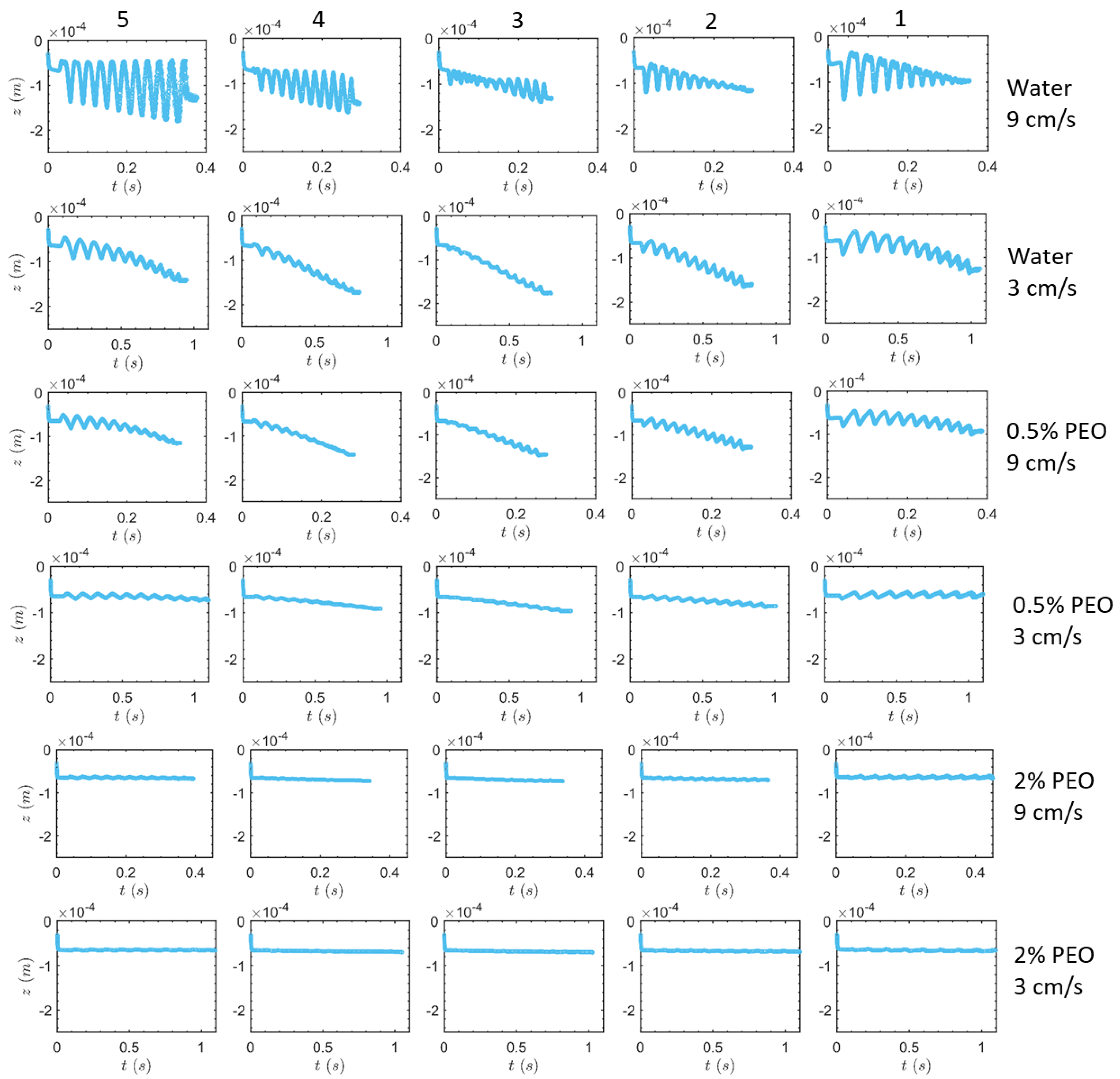
Figure 5 depicts the z-positions of particles as a function of time. The starting y-position of the particles, fluid viscosity, and flow speed are the major parameters that impact particle lateral motion. First, the impacts of the particles’ initial positions will be demonstrated. The particles at the top (smallest particles) and bottom (biggest particles) exhibit the most oscillations in the lateral (z) direction. This oscillation is caused by the previously described twisting. The amplitude of the oscillations is practically constant at the beginning, or in the portions closest to the channel’s intake. However, it skyrockets in the late segments. This is because the oscillations move more and more away from the side wall where the straight wall suppresses the lateral-direction flow, and thus, the secondary flow in the z-direction becomes a little stronger toward the inner side (Figure 3c). Furthermore, because the Dean drag force F D d is related to particle size, the largest particles, labels by 5, oscillate slightly more than the smallest particles, which are labeled by 1. The top right graph in Figure 5 compares the z-trajectories of the largest and smallest particles in pure water with a mean flow speed of 9 cm/s. They exhibit opposite z movements at intermediate times or, in the middle segments, due to the opposite lateral Dean drag depicted in Figure 2. The lateral flow at the center y height is weaker than at the upper or lower areas (Figure 3c) in the cross-section, so the oscillations appear to be considerably smaller for particles around the central height of the channel, which are labeled by 4 and 3. The lateral distance traveled by the middle-height particles is substantially shorter, so the time it takes for them to exit the channel has been significantly decreased.
As the flow mean speed increases (various rows in Figure 5), the oscillations in the z-direction increase due to the greater Dean number D e U m , especially for water. The terminal time for particles to reach the output reduces as the flow rate increases for each type of fluid. We see that this decrease in terminal time, as flow speed increases, appears to be more pronounced as fluid viscosity increases, owing to a smaller difference in z-oscillations at different flow rates in the fluid with a higher viscosity, particularly for 2% PEO solution. In contrast, for clean water, the bigger amplitude of z-oscillations at the higher flow rate lengthens the particles’ travel distance in the lateral direction and, ultimately, lengthens their arrival time (compare the topmost two rows in Figure 5). Therefore, the disparity between the terminal times at various rates is lessened. Additionally, we see that, for water, the oscillation’s range hits its maximum (the central position of cross-section z = −0.25 mm) late in the process and then stops expanding altogether. This plateau reappears when using 0.5% PEO solution at a flow rate of 9 cm/s. The oscillation does not reach the maximum z central position at the lower Re numbers, i.e., the higher viscosity or the lower flow rate, and it does not exhibit a plateau. The amplitude of the oscillations are also generally much smaller in the more viscous fluids because the Dean number D e 1 μ f .
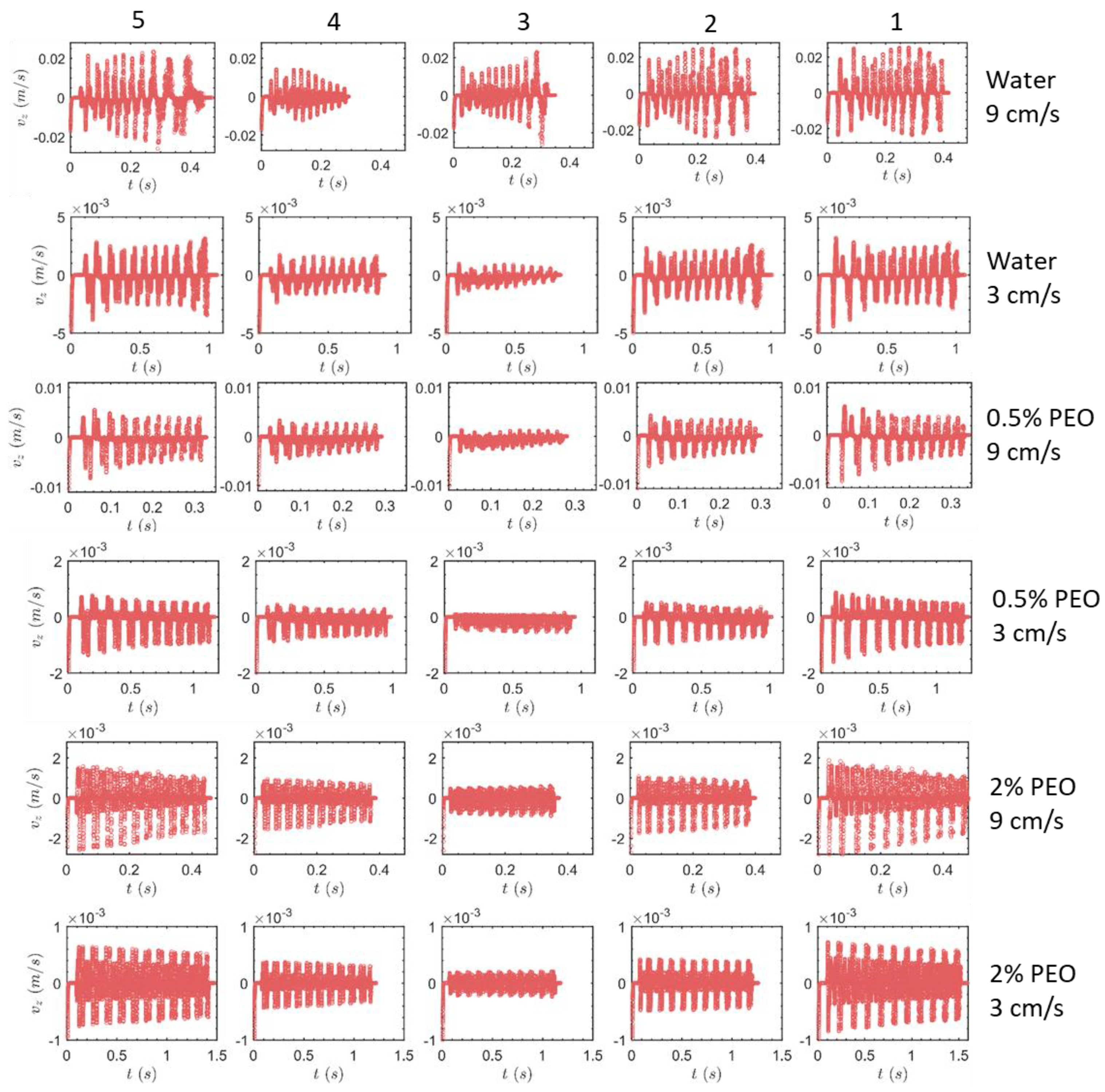
The oscillations of the particle’s lateral (z) velocity values are depicted in Figure 6. Due to the fact that the lateral migration velocity is U z ~ ρ f U 2 D h 2 2 r μ f [44], they grow when the flow rate increases or the viscosity of the fluid decreases. The particles in the central height exhibit lesser velocity oscillations than the particles at the top or bottom heights, due to the weaker secondary flow, in the same manner as the oscillations of z locations. Most importantly, it is noted that, as fluid viscosity increases, the oscillation amplitude shifts from increasing with time to decreasing with time. The development tendency of secondary flow structures in the channel between water and viscous PEO solutions is what causes this phenomena. For PEO solutions, the fluid is generally flowing inward in the z-direction (Figure 4c) in the early segments, which causes a significant amount of the particles’ deflections. The oscillations of particles in the z-direction are lessened in the latter segments because the fluid’s overall flow on the cross-section becomes upward or downward (Figure 4f). The water experiences an opposite development of the z-velocity oscillations compared to PEO solutions because the intensity of the converging upward secondary flow does not generally diminish in the latter segments, and it even grows slightly (compare Figure 2b plane 2 and Figure 3c plane 2). There is one exception, though, which is the particle labeled by 4, whose oscillation decays with time in pure water at 9 cm/s. This indicates that the trend of the oscillation heavily depends on the particle’s initial position. Consequently, the development of the secondary flow structure is very different at different specific positions on the cross-section.

3.1.2. Half-Circle-Segment Serpentine Channel

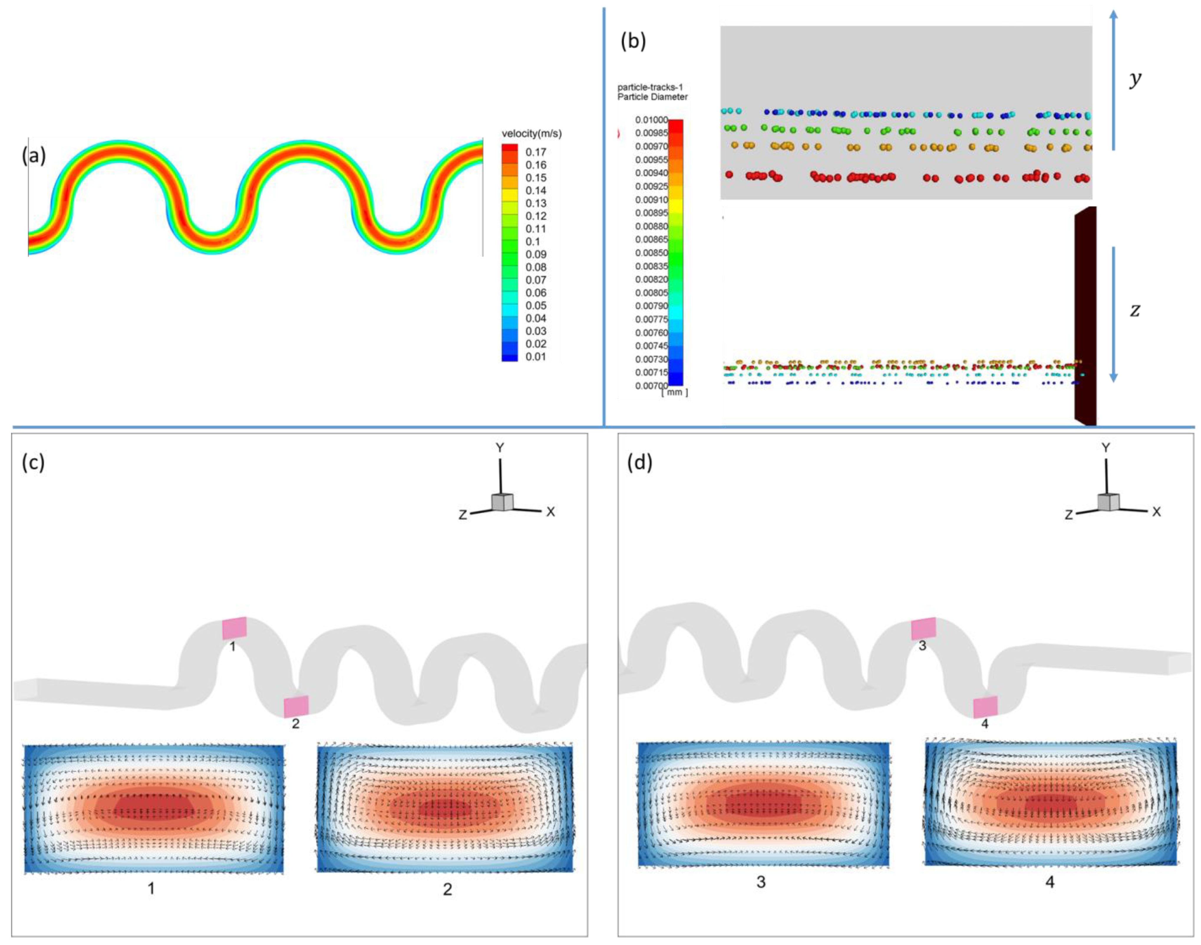
Figure 7 displays the z-direction position oscillations of particles in the serpentine microchannel with half-circle segments. The particles, labeled by 1 and 2, exhibit decaying oscillations in the case of pure water at a flow velocity of 9 cm/s, which is obviously different from the situation in the square-segment channel. Understanding this would come from examining the secondary flow structures and the spatial configuration of particles in Figure 8. In this instance, near the outlet, the particles 1 and 2 are located at the central height, where the flow in the z-direction is almost zero. In contrast, near the inlet, the particles 1 and 2 are closer to the top of the channel in the segments, where the secondary flow moving in the direction of z is stronger, which results in descending oscillations, in the z-direction, along the primary flow. The initial and final y-positions of particles 4 and 5 are always closer to the channel bottom (Figure 8b), and at this height, the strength of the secondary flow increases from the inlet to the outlet (compare Figure 8c,d), resulting in the growing oscillations. Nevertheless, these particles exhibit oscillations that grow over time. We do not notice the oscillations’ plateaus in any of the examples in the half-circle-segment serpentine channel because none of them reach the middle point of the z-direction (z = −0.25 mm). The bigger radius of curvature r , for the half-circle-segment serpentine channel and resulting smaller Dean numbers D e ~ 1 / r , are to blame for the generally weaker oscillations. Finally, similar to the square-segment serpentine channel, particularly in the cases of water (3 cm/s) and 0.5% PEO (9 cm/s) for particles labeled by 1 and 5, the z-position, at the early times, oscillates around a constant value of z. Then, at the late times, it oscillates around the lines located increasingly inward in the z-direction.
Figure S1 displays the z-velocity oscillations in the serpentine channel with half-circle segments. The butterfly-shaped oscillations of particle 3 in the pure water are the most visible phenomenon, and they become especially clear at flow rates of 9 cm/s. This is connected to the oscillations of particles 5 and 4 below it, which are growing, and the oscillations of particles 1 and 2 above it, which are declining. The middle-height particle, 3, exhibits both increasing and deteriorating patterns. As a result, the evolution takes the form of a butterfly, with growth occurring later and degradation occurring earlier. Additionally, we see that the circular-segment channel’s z-velocity oscillations are less symmetric than those in the square-segment channel. When comparing the flow structures in the top and lower parts of the segment (Figure 8c,d), the swirl is always stronger in the lower half circle due to the asymmetric geometry; thus, it makes sense to believe that effects of the secondary flow at the lower segment weigh and determine more in the particle lateral deflection. The net secondary flow of the upper and lower half circles is toward negative z at the intermediate height of y (Figure 8), where particles 1 and 2 are located and, therefore, oscillate more toward negative z. In contrast, the net lateral flow is toward the positive z at the bottom position, where particles 4 and 5 are situated and move more toward the positive z.

3.2. Particle Positions at the Outlet

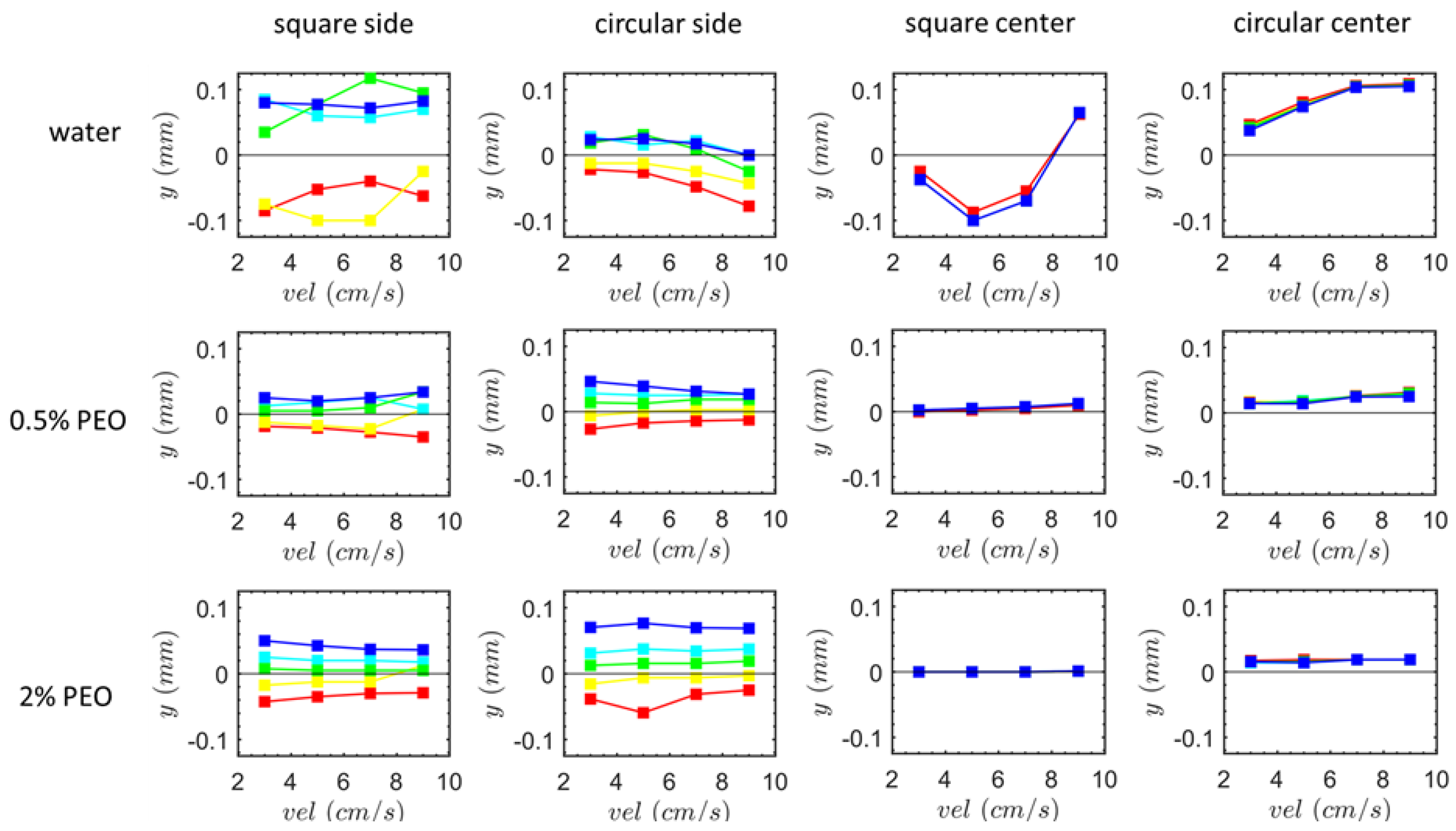
Figure 9 displays the vertical (y) positions of the various-sized particles at the exit. The flow of clean water in the square-segment channel is the most optimal option for the size separation destination. This separation efficiency does not vary obviously when the flow rate rises. Similar to the case of the 0.5% PEO solution in the square-segment channel, the separation efficiency increases marginally as the flow rate increases in the flow of pure water in the circular-segment channel. In contrast, the overall tendency in the situations of the circular-segment channel 0.5% PEO and square-segment channel 2% PEO is plainly focusing and mixing, which is consistent with the general observation that focusing becomes more efficient as R e increases [12,44]. In the curved channel and in the absence of inertial lift, the focusing efficiency δ = v f r v p t + ρ p ρ f d 2 v p t 18 r μ [63] increases as radial fluid velocity v f r increases. Here, v p t is the particle velocity in the primary-flow direction.
Except at very low R e numbers, it is widely understood that, when particles are randomly injected from the inlet into serpentine channels, focusing should occur at the highest R e numbers due to the secondary flow drag’s dominance over the inertia force [12,44]. As a result, particle separation is impossible. However, our results demonstrate both focusing and separation possibilities, which are mostly due to the starting release location of the particles—the side-wall—where the secondary flow state is quite complex. Conventionally, as the fluid viscosity increases, the minimum length L foc   min = w 2 ε 1.8 × 10 4 × U f 0.63 × ρ f D h μ D h 2 r 1.63 + ρ p ρ f d 2 U f / 18 r μ [44] necessary to achieve focusing should increase. When comparing the scenarios of the square-segment channel 0.5% PEO and square-segment channel 2% PEO, our results contradict this prediction. This is due to the fact that the secondary flow, taken into account by the formula, is situated in the middle of the channel, and it may not be similar to our circumstance, where the study’s primary emphasis is close to the side wall in the lateral direction. We should pay attention to the fact that the secondary flow switches the direction from the center to the edge (Figure 2, Figure 3 and Figure 8).
We also simulated the scenarios of the two-side-wall-symmetric sheath flow, which is mimicked by the particles that are injected from the center of the inlet in order to examine the consequences of the injection. The outcomes are displayed in Figure 9’s right two columns. Particle size significantly lessens its influence under this infusion. The particles of various sizes are only slightly separated in water flow and at low flow rates (3 cm/s). This shows that the separation efficiency is particularly sensitive to the introduction method, and it is advised to inject through pure water from the side wall or, equivalently, using a single-side-wall sheath flow imposed at the inlet. In the square-segment channel, as the flow rate increases in the water flow, the vertical position (before 5 cm/s) initially travels toward the lower position of the channel and then moves up, whereas the terminal vertical position in the circular segment channel rises monotonically as the flow rate rises and, finally, reaches the highest level (0.1 mm) of the channel. It should be noted that the vertical height of the outlet is designed to be somewhat higher than the inlet for the circular-segment channel. As a result, there is an overall flow that propels the particles upwards, and the strength of this flow increases as the flow speed increases, leading to the monotonic increase in the y-position as the flow rate increases.
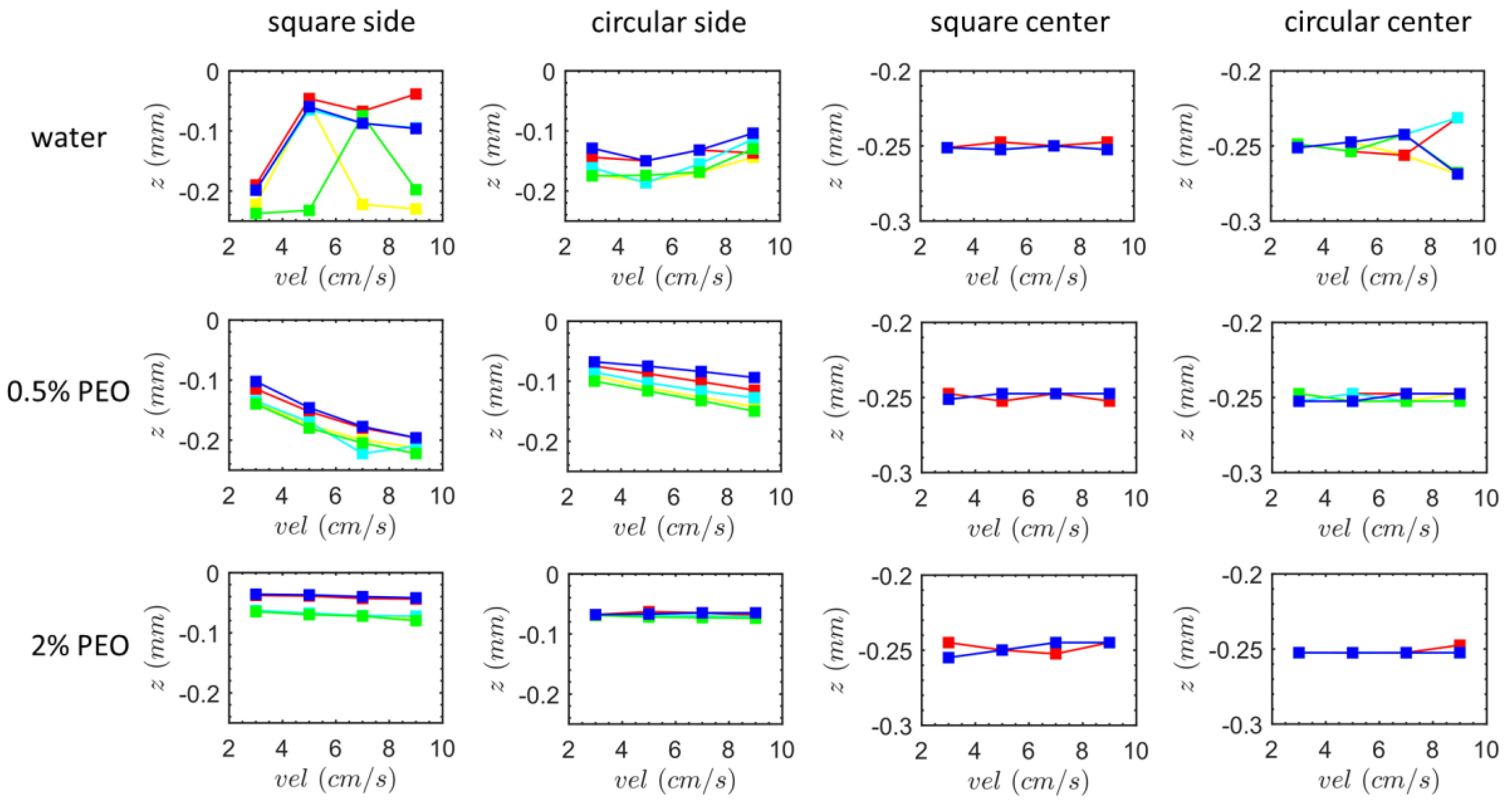
Figure 10 displays the particle lateral (z) positions at the outflow. We start by taking a look at instances of the single-side-wall sheath flow. In the square-segment channel with pure water, for a successful design of size separation, it only requires two collection ports located at the upper and lower positions of the outlet, respectively, because the smallest and largest particles emerge from two extremely different y-positions (Figure 9), yet they emerge from similar z-positions. In the case of the circular-segment channel with the 0.5% PEO solution, an intriguing phenomena is seen. Contrary to the vertical position depicted in Figure 9, there is an increasing separation in the z-direction as the flow rate rises. This suggests that the separation effectiveness varies in different directions. For the cases of the two-side-wall-symmetric sheath flow imposed from the inlet, except in the circular-segment channel with pure water, where the largest particle flows out from the outer z and the smallest particle flows out from the inner z, essentially no lateral motions of the particles are seen.
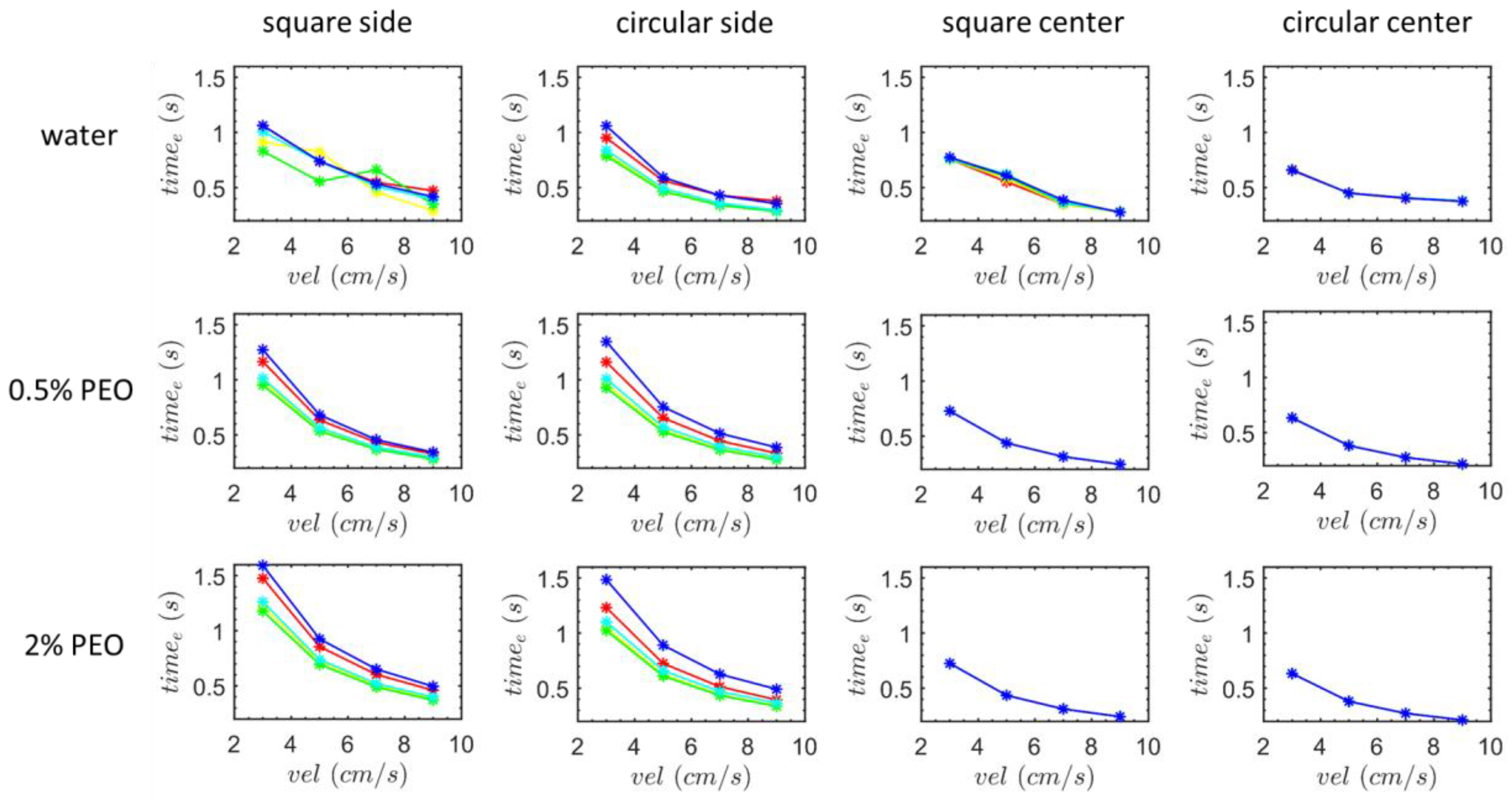
Figure 11 displays the particle movement’s exit time. Both the particles at the top (blue) and lower (red) beginning positions will, typically, take longer to reach the outflow for the single-side-wall sheath flow due to the greater oscillations in the lateral direction. The decreasing trend of the exit time for the flow rate is sharper for the largest and smallest particles, with the exception of the square-segment channel in water. Additionally, it appears that the more viscous fluid lengthens this time. The lines of the particles of various sizes collapse for the two-side-wall-symmetric sheath flow (the right two columns of Figure 11), and the more viscous fluid does not prolong this terminal time because the particles injected from the center inlet do not exhibit lateral movements in the z-direction.
Figures S2 and S3 demonstrate the z-position as a function of time, in the case of the two-side-wall-symmetric sheath flow, with Figure S2 for the square-segment channel and Figure S3 for the circular-segment channel, respectively. Both the two-side-wall-symmetric sheath flow (Figure S2) and the single-side-wall sheath flow (Figure 5) in the square-segment channel show oscillations, despite the fact that the particles for the two-side-wall-symmetric sheath deviate only slightly from the central line of the z-direction. The key distinction for the two-side-wall-symmetric sheath is that the increasing or decreasing tendency of the oscillations is highly different for particles of different sizes, notably including the flow of pure water at 9 cm/s, as well as the flow of 2% PEO at 3 cm/s. According to the channel shape and coordinate orientations illustrated in Figure 1, in the former case, particles 5, 4, and 1 migrate in the direction of the outer wall (positive z-direction), while particles 2 and 3 migrate in the opposite direction. In reality, the particles are subjected to Dean drag force, and they move in a specific direction as long as they stray slightly from the center of z. As seen in Figure 3, the secondary flow is obviously in the opposite direction from the center of z, which may contribute to this opposite overall trend of the oscillations. The tendency in this oscillation has been established in the early turns, and it grows in the later ones. The oscillations’ trends do not increase constantly when turns occur in the situations of water moving at 3 cm/s, 0.5% PEO moving at 3 cm/s, and 0.5% PEO moving at 9 cm/s; instead, they begin to plateau at an intermediate turn. While the latter case oscillates toward negative z, the two former cases display a trend toward positive z. The oscillations’ kink is significantly less obvious in the 2% PEO fluid, which has the highest viscosity.
For the two-side-wall-symmetric sheath flows in the circular-segment channel (Figure S3), with the exception of the 2% PEO at 3 cm/s, which has the lowest R e number, the influence of particle size can always be shown. This is because, compared to the square-segment channel (Figure 3c), the secondary flow in the circular-segment channel is more variable at different positions in the cross-section (Figure 8c,d), making it easier for particles of various sizes, initially located at different vertical positions, to be dragged in the opposite direction of z. Additionally, we observe that the oscillation amplitude growth in the circular-segment channel maintains rather than plateauing, which suggests that the flow is smoother, in this geometry, as a result of the smaller D e number that decreases as the curvature radius increases.

4. Conclusions

According to our research, most importantly, red (7 μ m ) and tumor cells (10 μ m ) can be distinguished based on their sizes in large cross-sectioned serpentine microchannels outside the range that the inertial lift works d D h > 0.07 . Most microchannel designs rely on the synergistic effects of Dean drag and inertial lift. The inertial lift effects are only discernible at relatively higher blockage ratios, suggesting that the microchannel’s cross-section shouldn’t be much larger than the size of a cell. Furthermore, only large flow rates allow for separation. As a result, there is high pumping pressure, which makes it simple to leak and harm microscopic channels made of PDMS, a soft substance. On the other hand, large cross-sectioned microchannels get over these limitations and are more preferred.
From our results, the phenomena is particularly noticeable in the square-segment channel and under the single-side-wall sheath flow. First, due to the four-grid-pattern distribution of the lateral velocity values at each turn, the particles twist in the lateral direction around each turn, and the large and tiny particles always deflect in opposing directions. The size separation is achieved at the channel outlet at R e = 56.7 and De = 17.8. This separation efficiency decreases as R e and De decrease. The lateral position and velocity values oscillate over time due to the twist trajectory. For the flow of water with the lowest viscosity, the oscillation develops in the lateral direction, toward the center of z, and eventually plateaus. As opposed to the flow of fluids when R e and De decrease, the oscillation always keeps far from the center of z and, thus, rises continuously. In contrast, the particle twist trajectory is weaker in the half-circle-segment channel due to the smaller De caused by the higher curvature radius r , and the size separation is not visible at the exit. In the circular-segment channel and in the flow of water, the oscillation of the lateral positions over time shows a diminishing trend instead of a growth. It appears that the two-side-wall-symmetric sheath flow does not aid in particle manipulation because the lateral motion of the particles is so feeble. Under this sheath flow, the overall trend of the oscillation of the lateral position or velocity, which is sometimes toward the inner-wall side in the lateral direction but sometimes toward the outer-wall side, is highly sensitive to particles’ initial positions and R e and De.

Supplementary Materials

The following supporting information can be downloaded at: https://www.mdpi.com/article/10.3390/pr11082411/s1, Figure S1: Velocity values (z) of particles of different sizes as function of time in the half-circle-segment serpentine microchannel under the side-wall sheath flow; Figure S2: Lateral (z) position of particles of different sizes as function of time in the square-segment serpentine microchannel under the two-side-wall-symmetric sheath flow; Figure S3: Lateral (z) position of particles of different sizes as function of time in the half-circle-segment serpentine microchannel under the two-side-wall-symmetric sheath flow.

Author Contributions

For this research article, Y.L. was in charge of performing simulations. Y.L. and L.Y. were in charge of writing the paper. X.H. and J.M. were in charge of analyzing data and plotting the figures. F.G. was in charge of advising and providing the funding. Y.G. was in charge of testing and verification of the UDF code used in Fluent. All authors have read and agreed to the published version of the manuscript.

Funding

This research was funded by the Natural Science Foundation of China (Grant Nos. 12102456), State Key Laboratory of Intelligent Construction and Healthy Operation and Maintenance of Deep Underground Engineering, China University of Mining & Technology, Xuzhou (SKLGDUEK2216), and Fundamental Research Funds for the Central Universities (2023KYJD1006).

Data Availability Statement

Data is available as requested, contact email: [email protected].

Acknowledgments

The study was approved by the China University of Mining and Technology (Xuzhou).

Conflicts of Interest

The authors declare no conflict of interest.

Nomenclature

F L Inertial lift force
ρ f Fluid density
U m a x Maximum velocity
d Particle diameter
h Channel height
D h Hydraulic radius
r Curvature radius
f Dimensionless inertial lift coefficient
m Particle mass
g Gravitational acceleration
U p Particle velocity
I Moment of inertia of particles
F p f Interaction force between particles and fluid
F c Collision contact force
ω Angular velocity of particles
t Time
F p Pressure gradient force
C d Drag coefficient
V p Particle volume
U f Fluid velocity
α f Volume fraction of fluid
μ f Fluid viscosity
k n Normal component of the spring stiffness
k t Tangential component of the spring stiffness
γ n Normal component of the damping coefficient
γ t Tangential component of the damping coefficient
δ n , i j Normal overlap of the two particles i ,   j
δ t , i j Tangential overlap of the two particles i ,   j
E e q Equivalent Young’s modulus
d e q Equivalent diameter
E Young’s modulus of particles
ν Poisson’s ratio of particles
G e q Equivalent shear modulus
m e q Equivalent mass
P Fluid pressure
τ f Stress tensor of the fluid
ρ p Particle density
R e Reynolds number
D e Dean number
F e Elastic lift force
C e Dimensionless coefficient of elastic lift
N 1 First normal stress difference
μ Viscosity of PEO at infinite shear rate
μ 0 Viscosity of PEO at zero shear rate
λ Constant of the shear rate in the Cross model
γ ˙ Shear rate
δ Curvature ratio
v f r Radial fluid velocity
v p t Particle velocity in primary direction

References

  1. Xu, J.; Liao, K.; Yang, X.; Wu, C.; Wu, W. Using single-cell sequencing technology to detect circulating tumor cells in solid tumors. Mol. Cancer 2021, 20, 104. [Google Scholar] [CrossRef]
  2. Xu, C.; He, X.; Ren, X.; Cheng, S. Direct detection of intracellular miRNA in living circulating tumor cells by tumor targeting nanoprobe in peripheral blood. Biosens. Bioelectron. 2021, 190, 113401. [Google Scholar] [CrossRef]
  3. Sinkala, E.; Sollier-Christen, E.; Renier, C.; Rosas-Canyelles, E.; Che, J.; Heirich, K.; Herr, A.E. Profiling protein expression in circulating tumour cells using microfluidic western blotting. Nat. Commun. 2017, 8, 14622. [Google Scholar] [CrossRef] [Green Version]
  4. Warkiani, M.E.; Khoo, B.L.; Wu, L.; Tay, A.K.P.; Bhagat, A.A.S.; Han, J.; Lim, C.T. Ultra-fast, label-free isolation of circulating tumor cells from blood using spiral microfluidics. Nat. Protoc. 2016, 11, 134–148. [Google Scholar] [CrossRef]
  5. Warkiani, M.E.; Guan, G.; Luan, K.B.; Lee, W.C.; Bhagat, A.A.S.; Chaudhuri, P.K.; Han, J. Slanted spiral microfluidics for the ultra-fast, label-free isolation of circulating tumor cells. Lab Chip 2014, 14, 128–137. [Google Scholar] [CrossRef] [PubMed] [Green Version]
  6. Jubery, T.; Srivastava, S.K.; Dutta, P. Dielectrophoretic separation of bioparticles in microdevices: A review. Electrophoresis 2014, 35, 691–713. [Google Scholar] [CrossRef]
  7. Zhang, H.; Chang, H.; Neuzil, P. DEP-on-a-chip: Dielectrophoresis applied to microfluidic platforms. Micromachines 2019, 10, 423. [Google Scholar] [CrossRef] [PubMed] [Green Version]
  8. Xuan, X. Recent advances in direct current electrokinetic manipulation of particles for microfluidic applications. Electrophoresis 2019, 40, 2484–2513. [Google Scholar] [CrossRef]
  9. Plouffe, B.D.; Murthy, S.K.; Lewis, L.H. Fundamentals and application of magnetic particles in cell isolation and enrichment: A review. Rep. Prog. Phys. 2014, 78, 016601. [Google Scholar] [CrossRef] [PubMed] [Green Version]
  10. Ding, X.; Lin, S.C.S.; Lapsley, M.I.; Li, S.; Guo, X.; Chan, C.Y.; Huang, T.J. Standing surface acoustic wave (SSAW) based multichannel cell sorting. Lab Chip 2012, 12, 4228–4231. [Google Scholar] [CrossRef] [PubMed] [Green Version]
  11. Liu, Y.; Lim, K.M. Particle separation in microfluidics using a switching ultrasonic field. Lab Chip 2011, 11, 3167–3173. [Google Scholar] [CrossRef] [PubMed]
  12. Carlo, D.D.; Irimia, D.; Tompkins, R.G.; Toner, M. Continuous inertial focusing, ordering, and separation of particles in microchannels. Proc. Natl. Acad. Sci. USA 2007, 104, 18892–18897. [Google Scholar] [CrossRef] [PubMed]
  13. Tang, W.; Zhu, S.; Jiang, D.; Zhu, L.; Yang, J.; Xiang, N. Channel innovations for inertial microfluidics. Lab Chip 2020, 20, 3485–3502. [Google Scholar] [CrossRef]
  14. Liu, C.; Guo, J.; Tian, F.; Yang, N.; Yan, F.; Ding, Y.; Sun, J. Field-free isolation of exosomes from extracellular vesicles by microfluidic viscoelastic flows. ACS Nano 2017, 11, 6968–6976. [Google Scholar] [CrossRef] [PubMed] [Green Version]
  15. Fallahi, H.; Zhang, J.; Phan, H.P.; Nguyen, N.T. Flexible microfluidics: Fundamentals, recent developments, and applications. Micromachines 2019, 10, 830. [Google Scholar]
  16. Liu, Y.; Zhao, W.; Cheng, R.; Puig, A.; Hodgson, J.; Egan, M.; Mao, L. Label-free inertial-ferrohydrodynamic cell separation with high throughput and resolution. Lab Chip 2021, 21, 2738–2750. [Google Scholar] [CrossRef]
  17. Wu, Z.; Chen, Y.; Wang, M.; Chung, A.J. Continuous inertial microparticle and blood cell separation in straight channels with local microstructures. Lab Chip 2016, 16, 532–542. [Google Scholar] [CrossRef]
  18. Sun, J.; Xianyu, Y.; Li, M.; Liu, W.; Zhang, L.; Liu, D.; Liu, C.; Hu, G.; Jiang, X. A microfluidic origami chip for synthesis of functionalized polymeric nanoparticles. Nanoscale 2013, 5, 5262–5265. [Google Scholar] [CrossRef] [Green Version]
  19. Bazaz, S.R.; Mihandust, A.; Salomon, R.; Joushani, H.A.N.; Li, W.; Amiri, H.A.; Warkiani, M.E. Zigzag microchannel for rigid inertial separation and enrichment (Z-RISE) of cells and particles. Lab Chip 2022, 22, 4093–4109. [Google Scholar] [CrossRef]
  20. Chung, A.J.; Gossett, D.R.; Carlo, D.D. Three dimensional, sheathless, and high-throughput microparticle inertial focusing through geometry-induced secondary flows. Small 2013, 9, 685–690. [Google Scholar] [CrossRef]
  21. Xiang, N.; Chen, K.; Dai, Q.; Jiang, D.; Sun, D.; Ni, Z. Inertia-induced focusing dynamics of microparticles throughout a curved microfluidic channel. Microfluid. Nanofluid. 2015, 18, 29–39. [Google Scholar] [CrossRef]
  22. Oakey, J.; Applegate, R.W.; Arellano, E.; Carlo, D.D.; Graves, S.W.; Toner, M. Particle focusing in staged inertial microfluidic devices for flow cytometry. Anal. Chem. 2010, 82, 3862–3867. [Google Scholar] [CrossRef] [PubMed] [Green Version]
  23. Chung, A.J.; Pulido, D.; Oka, J.C.; Amini, H.; Masaeli, M.; Carlo, D.D. Microstructure-induced helical vortices allow single-stream and long-term inertial focusing. Lab Chip 2013, 13, 2942–2949. [Google Scholar] [CrossRef] [PubMed]
  24. Segre, G.; Silberberg, A. Behaviour of macroscopic rigid spheres in Poiseuille flow Part 2. Experimental results and interpretation. J. Fluid Mech. 1962, 14, 136–157. [Google Scholar] [CrossRef]
  25. Segre, G.; Silberberg, A. Radial particle displacements in Poiseuille flow of suspensions. Nature 1961, 189, 209–210. [Google Scholar] [CrossRef]
  26. Amini, H.; Lee, W.; Di Carlo, D. Inertial microfluidic physics. Lab Chip 2014, 14, 2739–2761. [Google Scholar] [CrossRef] [PubMed]
  27. Shen, S.; Tian, C.; Li, T.; Xu, J.; Chen, S.W.; Tu, Q.; Wang, J. Spiral microchannel with ordered micro-obstacles for continuous and highly-efficient particle separation. Lab Chip 2017, 17, 3578–3591. [Google Scholar] [CrossRef]
  28. Ghadami, S.; Kowsari-Esfahan, R.; Saidi, M.S.; Firoozbakhsh, K. Spiral microchannel with stair-like cross section for size-based particle separation. Microfluid. Nanofluid. 2017, 21, 1–10. [Google Scholar] [CrossRef]
  29. Bhagat, A.A.S.; Kuntaegowdanahalli, S.S.; Papautsky, L. Enhanced particle filtration in straight microchannels using shear-modulated inertial migration. Phys. Fluids 2008, 20, 101702–101704. [Google Scholar] [CrossRef] [Green Version]
  30. Karampelas, I.H.; Gómez-Pastora, J. Novel approaches concerning the numerical modeling of particle and cell separation in microchannels: A review. Processes 2022, 10, 1226. [Google Scholar] [CrossRef]
  31. Seo, J.; Lean, M.H.; Kole, A. Membraneless microseparation by asymmetry in curvilinear laminar flows. J. Chromatogr. A 2007, 1162, 126–131. [Google Scholar] [CrossRef] [PubMed]
  32. Li, D.; Lu, X.; Song, Y.; Wang, J.; Li, D.; Xuan, X. Sheathless electrokinetic particle separation in a bifurcating microchannel. Biomicrofluidics 2016, 10, 054104. [Google Scholar] [CrossRef] [PubMed] [Green Version]
  33. Bhagat, A.A.S.; Kuntaegowdanahalli, S.S.; Papautsky, L. Inertial microfluidics for continuous particle filtration and extraction. Microfluid. Nanofluid. 2009, 7, 217–226. [Google Scholar] [CrossRef]
  34. Choi, Y.; Seo, K.; Lee, S. Lateral and cross-lateral focusing of spherical particles in a square microchannel. Lab Chip 2011, 11, 460–465. [Google Scholar] [CrossRef] [PubMed] [Green Version]
  35. Hur, S.; Henderson-MacLennan, N.K.; McCabe, E.R.B.; Carlo, D.D. Deformability-based cell classification and enrichment using inertial microfluidics. Lab Chip 2011, 11, 912–920. [Google Scholar] [CrossRef]
  36. Gossett, D.R.; Tse, H.; Dudani, J.; Goda, K.; Woods, T.A.; Graves, S.W.; Di Carlo, D. Inertial manipulation and transfer of microparticles across laminar fluid streams. Small 2012, 8, 2757–2764. [Google Scholar] [CrossRef]
  37. Di Carlo, D.; Edd, J.F.; Humphry, K.J.; Stone, H.A.; Toner, M. Particle Segregation and Dynamics in Confined Flows. Phys. Rev. Lett. 2009, 102, 1–4. [Google Scholar] [CrossRef] [Green Version]
  38. Hur, S.; Tse, H.; Di Carlo, D. Sheathless inertial cell ordering for extreme throughput flow cytometry. Lab Chip 2010, 10, 274–280. [Google Scholar] [CrossRef]
  39. Vasseur, P.; Cox, R.G. The lateral migration of a spherical particle in two-dimensional shear flows. J. Fluid Mech. 1976, 78, 385–413. [Google Scholar] [CrossRef]
  40. Feng, J.; Hu, H.H.; Joseph, D.D. Direct simulation of initial value problems for the motion of solid bodies in a Newtonian fluid Part 1. Sedimentation. J. Fluid Mech. 1994, 261, 95–134. [Google Scholar] [CrossRef] [Green Version]
  41. Edd, J.F.; Di Carlo, D.; Humphry, K.J.; Köster, S.; Irimia, D.; Weitz, D.A.; Toner, M. Controlled encapsulation of single-cells into monodisperse picolitre drops. Lab Chip 2008, 8, 1262–1264. [Google Scholar] [CrossRef] [Green Version]
  42. Gossett, D.R.; Di Carlo, D. Particle focusing mechanisms in curving confined flows. Anal. Chem. 2009, 81, 8459–8465. [Google Scholar] [CrossRef]
  43. Lee, M.G.; Shin, J.H.; Bae, C.Y.; Choi, S.; Park, J.K. Label-free cancer cell separation from human whole blood using inertial microfluidics at low shear stress. Anal. Chem. 2013, 85, 6213–6218. [Google Scholar] [CrossRef]
  44. Zhang, J.; Li, W.; Li, M.; Alici, G.; Nguyen, N.T. Particle inertial focusing and its mechanism in a serpentine microchannel. Microfluid. Nanofluid. 2014, 17, 305–316. [Google Scholar] [CrossRef]
  45. Jiang, D.; Huang, D.; Zhao, G.; Tang, W.; Xiang, N. Numerical simulation of particle migration in different contraction–expansion ratio microchannels. Microfluid. Nanofluid. 2019, 23, 7. [Google Scholar] [CrossRef]
  46. Elghobashi, S. On predicting particle-laden turbulent flows. Appl. Sci. Res. 1994, 52, 309–329. [Google Scholar] [CrossRef]
  47. Zhang, S.; Zhang, B.; Liu, X.; Shan, J. Application of a particle-grid hybrid method in multiphase flow calculation. J. Nucl. Sci. Technol. 2020, 57, 1199–1214. [Google Scholar] [CrossRef]
  48. Kidanemariam, A.G.; Uhlmann, M. Formation of sediment patterns in channel flow: Minimal unstable systems and their temporal evolution. J. Fluid Mech. 2017, 818, 716–743. [Google Scholar] [CrossRef] [Green Version]
  49. Fernandes, C.; Semyonov, D.; Ferrás, L.L.; Nóbrega, J.M. Validation of the CFD-DPM solver DPMFoam in OpenFOAM® through analytical, numerical and experimental comparisons. Granul. Matter 2018, 20, 64. [Google Scholar] [CrossRef]
  50. Sippola, P.; Kolehmainen, J.; Ozel, A.; Liu, X.; Saarenrinne, P.; Sundaresan, S. Experimental and numerical study of wall layer development in a tribocharged fluidized bed. J. Fluid Mech. 2018, 849, 860–884. [Google Scholar] [CrossRef] [Green Version]
  51. Shalaby, H.; Wozniak, K.; Wozniak, G. Numerical calculation of particle-laden cyclone separator flow using LES. Eng. Appl. Comput. Fluid Mech. 2008, 2, 382–392. [Google Scholar] [CrossRef] [Green Version]
  52. Song, C.; Pei, B.; Jiang, M.; Wang, B.; Xu, D.; Chen, Y. Numerical analysis of forces exerted on particles in cyclone separators. Powder Technol. 2016, 294, 437–448. [Google Scholar] [CrossRef]
  53. Liu, C.; Hu, G.; Jiang, X.; Sun, J. Inertial focusing of spherical particles in rectangular microchannels over a wide range of Reynolds numbers. Lab Chip 2015, 15, 1168–1177. [Google Scholar] [CrossRef]
  54. Zhu, H.; Zhou, Z.; Yang, R.; Yu, A. Discrete particle simulation of particulate systems: A review of major applications and findings. Chem. Eng. Sci. 2008, 63, 5728–5770. [Google Scholar]
  55. Tsuji, Y.; Tanaka, T.; Ishida, T. Lagrangian numerical simulation of plug flow of cohesionless particles in a horizontal pipe. Powder Technol. 1992, 71, 239–250. [Google Scholar] [CrossRef]
  56. Mindlin, R.D. Compliance of elastic bodies in contact. J. Appl. Mech. 1949, 16, 259–268. [Google Scholar] [CrossRef]
  57. Lien, C.C.; Wu, M.C.; Ay, C. Study on the Young’s modulus of red blood cells using atomic force microscope. Appl. Mech. Mater. 2014, 627, 197–201. [Google Scholar] [CrossRef]
  58. Javanmardi, Y.; Colin-York, H.; Szita, N.; Fritzsche, M.; Moeendarbary, E. Quantifying cell-generated forces: Poisson’s ratio matters. Commun. Phys. 2021, 4, 237. [Google Scholar] [CrossRef]
  59. Grover, W.H.; Bryan, A.K.; Diez-Sliva, M.; Manalis, S.R. Measuring single-cell density. Proc. Natl. Acad. Sci. USA 2011, 108, 10992–10996. [Google Scholar] [CrossRef]
  60. Liu, C.; Xue, C.; Chen, X.; Shan, L.; Tian, Y.; Hu, G. Size-based separation of particles and cells utilizing viscoelastic effects in straight microchannels. Anal. Chem. 2015, 87, 6041–6048. [Google Scholar] [CrossRef] [Green Version]
  61. Crowley, M.M.; Zhang, F.; Koleng, J.J.; McGinity, J.W. Stability of polyethylene oxide in matrix tablets prepared by hot-melt extrusion. Biomaterials 2002, 23, 4241–4248. [Google Scholar] [CrossRef] [PubMed]
  62. Ebagninin, K.W.; Benchabane, A.; Bekkour, K. Rheological characterization of poly (ethylene oxide) solutions of different molecular weights. J. Colloid Interface Sci. 2009, 336, 360–367. [Google Scholar] [CrossRef] [PubMed]
  63. Zhu, J.; Tzeng, T.R.; Hu, G.; Xuan, X. DC dielectrophoretic focusing of particles in a serpentine microchannel. Microfluid. Nanofluid. 2009, 7, 751–756. [Google Scholar] [CrossRef]
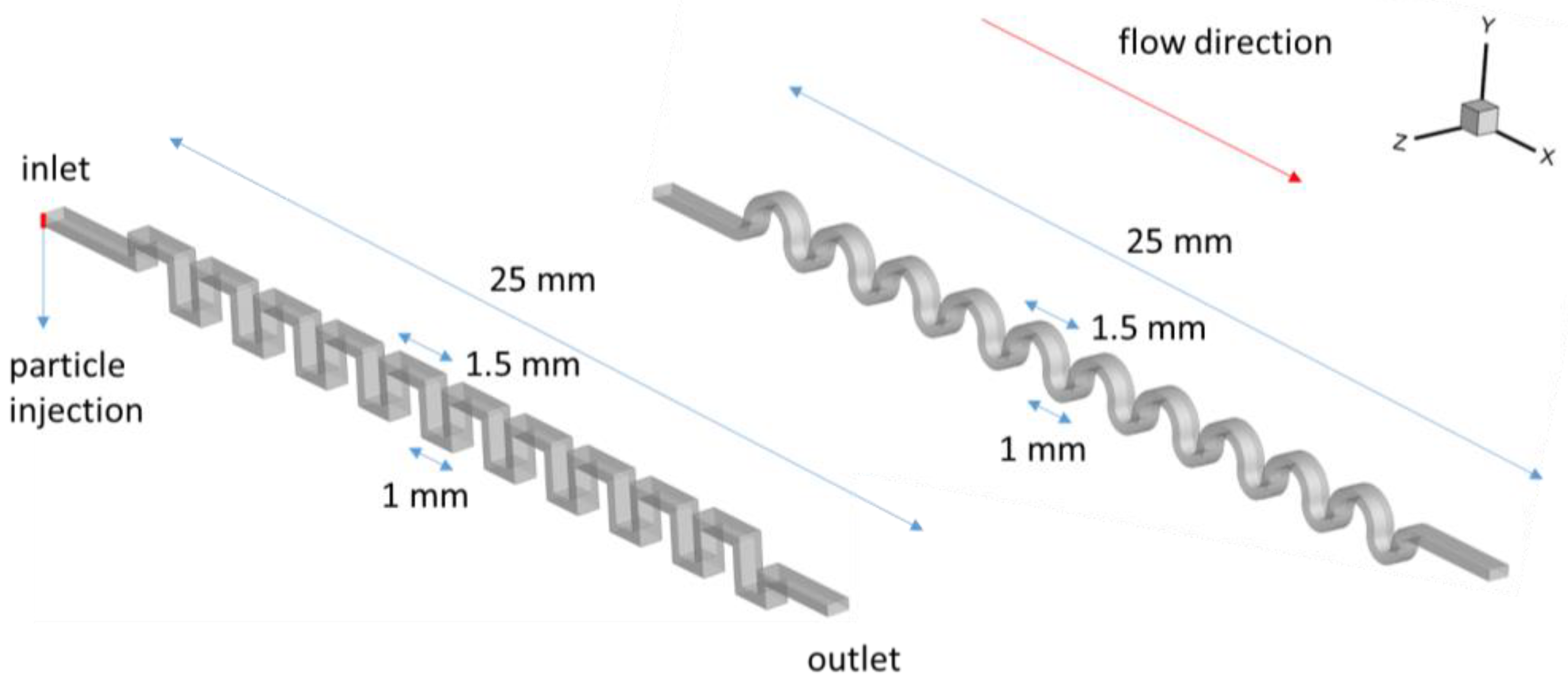
Figure 1. The geometries of the two serpentine microchannels: (Left) the square-segment-serpentine microchannel; (Right) the half-circle-segment serpentine microchannel. The particle factory for injecting particles is marked by the red line on the inlet face of the left microchannel.
Processes 11 02411 g001
Figure 2. Twisted lateral motion of particles in water in the square-segment serpentine channel at the fluid inlet speed of 9 cm/s, with the single-side-wall sheath flow. (a) Trajectories of the particles are colored by particle size near the channel inlet. The inset is the front view of the distribution of the fluid velocity. (b) The fluid velocity field on three selected slices. (c) Schematic diagram of large and small particles, twisted by negative-z-valued fluid zone and positive-z-valued fluid zone, respectively. In the flow field shown in (c), the color represents the z-velocity value of the fluid, and the vectors are the fluid velocity vectors. The velocity field is on the slice located at the first turn from the inlet. The angle between this plane and the primary flow direction is 135 ° . (d) Contrary to (c), this is the schematic diagram of large and small particles twisted by positive-z-valued fluid zone and negative-z-valued fluid zone, respectively. The flow field in (d) is on the slice located at the second turn from the inlet. (e) z-velocity fields on slices at the turns located at the opposite sides of the channel.
Processes 11 02411 g002
Figure 3. Particle configuration and velocity values in the x–y plane in the same simulation case as in Figure 2, as well as the particle positions at the outlet: (a) spatial configuration of particles of different sizes at the front view of the channel; (b) distribution of particles’ velocity at the front view of the channel; (c) flow velocity fields on three slices at the bottom horizontal part of the segment nearest to the outlet; (d) positions of particles of different sizes in the z-direction nearest to the outlet; (e) positions of particles of different sizes in the y-direction nearest to the outlet.
Processes 11 02411 g003
Figure 4. Particle configurations in 2% PEO solution in the square-segment serpentine channel at the fluid inlet speed of 3 cm/s, under the single-side-wall sheath flow: (a) trajectories of the particles colored by particle size near the channel inlet; (b) the front view of the distribution of the fluid velocity; (c) the fluid velocity field on three slices near the inlet at the positions same as in Figure 2b; (d) positions of particles of different sizes in the y-direction at the exit; (e) positions of particles of different sizes in the z-direction at the exit; (f) the fluid velocity field on three slices near the outlet, in the same configuration as in Figure 3c.
Processes 11 02411 g004
Figure 5. The lateral (z) positions of particles of different sizes, as functions of time, in the square-segment serpentine microchannel under the single-side-wall sheath flow. The top left picture shows the twist of the particle trajectory near the inlet. There are five streams of particles, and the particle size decreases from the bottom (red) to the top (blue), which are labeled by 5 to 1, respectively. The five columns show the data for the particles of each size. From the left to the right, the particles are labeled by 5 to 1. Each row includes the data for each flow condition that is the fluid type and the flow speed. The top right graph shows the comparison of the data of the largest particle and the smallest particle at the flow speed of 9 cm/s in pure water.
Processes 11 02411 g005
Figure 6. Velocity values in the lateral (z) direction of particles of different sizes as functions of time. The indexes for the columns and the rows are the same as those of Figure 5.
Processes 11 02411 g006
Figure 7. Lateral (z) position of particles of different sizes, as functions of time, in the circular-segment serpentine microchannel under the single-side-wall sheath flow.
Processes 11 02411 g007
Figure 8. In the case of the pure water and at the fluid inlet speed of 9 cm/s in the half-circle-segment serpentine channel and under the single-side-wall sheath flow, (a) the front view of the distribution of the fluid velocity; (b) positions of particles of different sizes at the outlet in the y and z-directions, respectively; (c) flow structures at the cross-sections near the inlet; (d) flow structures at the cross-sections near the outlet.
Processes 11 02411 g008
Figure 9. The vertical (y) position of particles at the outlet of the square-segment and circular-segment serpentine microchannels. Particles of different sizes are marked using colors that are the same as the colors used to represent the particle size in Figure 2, Figure 4, Figure 5 and Figure 8. The left two columns show the results under the single-side-wall sheath flow. The right two columns show the results under the two-side-wall-symmetric sheath flow.
Processes 11 02411 g009
Figure 10. The lateral (z) position of particles at the outlet of the square-segment and circular-segment serpentine microchannels. Particles of different sizes are marked using colors that are the same as the colors used to represent the particle size in Figure 2, Figure 4, Figure 5 and Figure 8.
Processes 11 02411 g010
Figure 11. Exit time of particles’ motions in different cases. Particles of different sizes are marked using colors that are the same as the colors used to represent the particle size in Figure 2, Figure 4, Figure 5 and Figure 8. The asterisks are the makers specific to the exit time this variable.
Processes 11 02411 g011
Table 1. Cross model parameters of PEO solutions of molecular weight 4 × 10 5   g / mol of two different concentrations.
Concentration (%) λ s m μ 0   ( P a · s ) μ   ( P a · s )  
0.50.00060.790.0050.003
20.00330.730.0490.008
Disclaimer/Publisher’s Note: The statements, opinions and data contained in all publications are solely those of the individual author(s) and contributor(s) and not of MDPI and/or the editor(s). MDPI and/or the editor(s) disclaim responsibility for any injury to people or property resulting from any ideas, methods, instructions or products referred to in the content.