Article

Hybrid Dynamical Modeling and Control of Permanent Magnet Synchronous Motors: Hardware-in-the-Loop Verification

by
Mahmoud F. Elmorshedy
1,2,
Dhafer Almakhles
1 and
Mahmoud Abdelrahim
1,3,*
1
Renewable Energy Laboratory, College of Engineering, Prince Sultan University, Riyadh 11586, Saudi Arabia
2
Electrical Power and Machines Engineering Department, Faculty of Engineering, Tanta University, Tanta 31521, Egypt
3
Department of Mechatronics Engineering, Faculty of Engineering, Assiut University, Assiut 71515, Egypt
*
Author to whom correspondence should be addressed.
Processes 2023, 11(8), 2370; https://doi.org/10.3390/pr11082370
Submission received: 21 June 2023 / Revised: 27 July 2023 / Accepted: 3 August 2023 / Published: 7 August 2023
(This article belongs to the Topic Modeling, Optimization, and Control of Energy Systems)

Abstract

:
The stabilization of a permanent magnet synchronous motor using digital controllers requires the design of both the feedback law and an appropriate sampling frequency. Moreover, the design approach must be robust against existing uncertainties, such as disturbances and parameter variations. In this paper, we develop a stabilizing state feedback nonlinear control scheme for the permanent magnet synchronous motor. Moreover, we consider the case where the feedback signal is transmitted over a digital platform, and we derive the stabilizing sampling frequency, such that the stability of the closed-loop system is maintained. We design the controller by emulation, where the closed-loop stability is first established in continuous time; we then take into account the effect of sampling. The feedback law consists of two parts: feedback linearization and robust linear quadratic regulator for the linearized mode. The robustness is achieved by augmenting the state space model, with additional states representing the tracking errors of the motor speed and the motor current. Then, to cope with sampling, we estimate the maximally allowable sampling interval to reduce the sampling frequency while preserving the closed-loop stability. The overall system is modeled as a hybrid dynamical system, which allows handling both the continuous-time and discrete-time dynamics. The effectiveness of the proposed technique is illustrated by simulation and verified experimentally using a hardware-in-the-loop setup. Upon implementing the proposed approach, the obtained sampling interval was around 91 ms, making it suitable for digital implementation setups.

1. Introduction

Electric vehicles (EVs) are viable alternatives to the problems caused by their gas-powered counterparts, including reduced gas emissions, improved acceleration and energy efficiency, less maintenance, and compatibility with electric grids [1,2,3,4]. In this regard, the selection of rotary machines that can be used for EVs and the applied control technique play central roles in the overall performance of EVs. The main factors in selecting these electric motors include high efficiency, high power density, and low cost. A common solution for light-duty EV designs meeting these criteria involves the use of permanent magnet synchronous motors (PMSMs) owing to their compact size and high-power density [5,6,7,8]. Beyond motor selection, the control methodology of the PMSM also needs to be carefully designed in order to ensure optimal and robust performance, which is the point of interest of this paper.
We consider the scenario where the EV’s PMSM is monitored by analog sensors for speed and current feedback, while the control signal is generated by a digital platform—typical in practice. As a result, the feedback signals need to be sampled at discrete time instants by means of analog-to-digital converters (ADCs) before being sent to the controller. The appropriate design of the sampling frequency and the feedback law are crucial to guarantee the desired performance properties. Indeed, if the sampling frequency is not well designed, it can significantly deteriorate the closed-loop performance or even destabilize the system. To avoid this issue, it is often assumed that the sampling frequency can be chosen sufficiently high (Nyquist criterion), which could be a restrictive requirement in practice. Moreover, this control architecture involves interactions between continuous-time and discrete-time phenomena, i.e., the closed-loop system has hybrid dynamics, which require dedicated tools for the modeling and design of control approaches.
In the literature, many control methods for the PMSM have been developed, including scalar control [9,10,11], field-oriented control (FOC) [12,13,14], direct torque control (DTC) [15,16,17,18,19], PI control [20,21,22], and model predictive control (MPC) [23,24,25]. However, all these results are developed for either continuous-time or discrete-time cases but are not adapted for sampled-data implementation. The sampled-data control problem for PMSM has been studied in only a few works [26,27,28,29,30,31,32,33]. The authors of [26,27,28] studied the stabilization of the PMSM under periodic sampling with different control methods, while [28,29] investigated this problem for output reference tracking. The control design technique of [30] is based on the passivity approach, while in [31], fuzzy controllers were designed using the Lyapunov–Krasovskii functional strategy. In [32], the sampled-data sliding mode controller was constructed; it was based on the symplectic Euler approach. The controller in [33] was synthesized and based on an extended high-gain state observer. Compared to those results, we derive an estimate of the minimum stabilizing sampling frequency while maintaining the closed-loop stability. Moreover, we formulate the problem as a hybrid dynamical system in order to address both discrete-time and continuous-time behaviors; this was not conducted in the previously mentioned results. In addition, we synthesize the feedback law to achieve reference tracking for motor speed and current rather than stabilization around the origin. To the best of our knowledge, this is the first work that studies this problem in the framework of hybrid dynamical systems.
We design the controller by emulation, where we first stabilize the overall drive system in continuous time, and subsequently study the effect of sampling. The feedback law consists of two parts: nonlinear and linear. The nonlinear component is employed to decouple the nonlinear terms of the PMSM using the feedback linearization technique. The linear control action is then activated to provide optimal and robust behavior for the closed-loop system. The optimal control is based on the LQR method, such that the tracking errors of the motor speed and the motor current converge to zero, while the control effort is reduced. The robust control is achieved by augmenting the state vector with additional states representing the tracking errors, allowing for zero steady-state errors against external disturbances and parameter uncertainties. Next, we take into account the effect of sampling and we provide an estimate of the lower bound of the sampling frequency that maintains the closed-loop stability/performance. The result is based on the well-known technique in [34,35], which we adapt for the PMSM application. The approach has been tested under different operating conditions, including:
  • Constant speed with variable load torque: The reference speed trajectory is fixed while the torque disturbance varies along the simulation time window;
  • Variable speed with constant load torque: The load disturbance is fixed while different step references for motor speed are given;
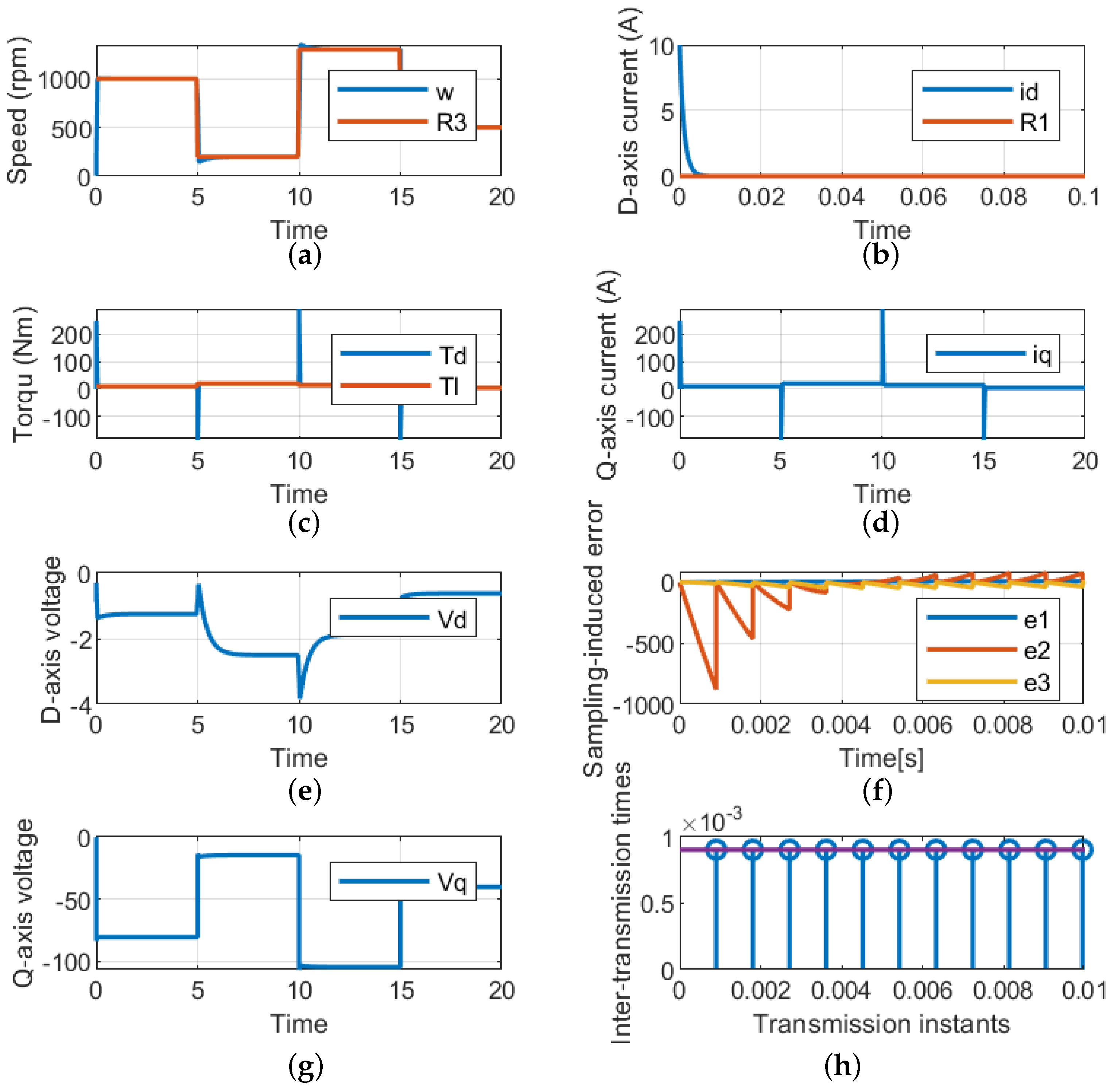
  • Variable speed with variable load torque: The above two cases are combined in this implementation.
In all theoperating conditions, the PMSM shows satisfactory output response where the required speed reference is tracked in minimal time despite the load disturbances.
The closed-loop system includes interactions between discrete-time and continuous-time phenomena (i.e., a hybrid dynamical system). To account for such combined behaviors, the system is modeled using the hybrid framework of [36], as in [37,38]. Then, we provide sufficient conditions to guarantee the stability of the closed-loop system. After that, the proposed approach is demonstrated by simulation and verified on an experimental setup using hardware-in-the-loop. The simulation results and the experimental verification are both consistent with the stability analysis, justifying the proposed approach.
The contribution of this work is as follows:
  • An optimal nonlinear control method is proposed for PMSM, which is robust against load disturbances;
  • The minimum stabilizing sampling frequency is derived for the sampled- data implementation;
  • The overall drive system modeling is formulated as a hybrid dynamical system to deal with discrete-time and continuous-time behaviors.
By following the emulation approach, a stabilizing feedback law is first synthesized in continuous time. Then, the sampling effect is considered and the hybrid dynamical model is derived. Afterward, sufficient conditions are provided to derive the maximum allowable sampling interval and preserve the closed-loop stability. Finally, closed-loop stability is analyzed by using appropriate Lyapunov functions to validate the design procedure.
The remainder of the paper is organized as follows. Preliminaries are presented in Section 2 and the problem formulation is stated in Section 3. The design of the control method and the derivation of the stabilizing sampling frequency are presented in Section 4 and Section 5, respectively. The simulation results are presented in Section 5 and verified experimentally, as shown in Section 5. Conclusions are presented in Section 8.

2. Notation and Preliminaries

The sets of both real numbers and positive real numbers are represented by the symbols R and R 0 , respectively, and the set of positive integers is denoted by N . The maximum and minimum eigenvalues of a real matrix A are, respectively, denoted by λ min ( A ) and λ max ( A ) . The transpose of matrix A is written as A T . For vectors x R n x and y R n y , the notion ( x , y ) represents [ x T , y T ] T . The Euclidean norm of a vector x R n x is written as | x | : = x T x and the Euclidean norm of a matrix A R n × m is given by | A | : = λ max ( A T A ) .
For a dynamical system with continuous-time evolution x ˙ = F ( x ) and discrete-time behavior x + G ( x ) , the formulation of the hybrid dynamics using the framework of [36] is given by
x ˙ = F ( x ) x C , x + G ( x ) x D ,
where C and D denote the flow set and the jump set, respectively. The time domain at which the solution of (1) is defined is called the hybrid time domain.

3. Problem Formulation

The dynamic of the PMSM, which is considered to be the main driver of the EV, is derived before going through the specifics of the control system that is proposed. There are two frames used to derive the dynamic model of the PMSM: the stationary reference frame [39] and the synchronous reference frame [40,41]. Considering the complexities and time-variance of the stationary reference frame, we use the dq-axis synchronous reference frame, in which the voltage and current variables are constant values. The following relations represent the mathematical dynamic model of the PMSM in dq-axis coordinates through the conversion of the three-phase to two-phase using the Park transformation [42]. The equivalent circuit of the PMSM is shown in Figure 1.
The stator voltage equations can be represented by
u d s = R s i d s + p λ d s ω e λ q s u q s = R s i q s + p λ q s + ω e λ d s ,
where ( u d s , i d s ) , ( u q s , i q s ) are the stator voltage and current in the d-axis and q-axis, respectively, R s is the stator resistance, p is the derivative term, λ d s , λ q s are the d-axis and q-axis flux linkages, and ω e is the electrical rotating speed. The d q -axis stator flux linkage equations are
λ d s = L s i d s + λ m , λ q s = L s i q s ,
where L s is the stator inductance and λ m is the permanent magnet flux linkage. Meanwhile, the mechanical equation, including the developed torque equation, is given by
T d = 2 3 P 2 λ m i q s = T + J π 30 d N m d t + B π 30 N m ,
where T d is the developed torque, P is the number of poles, T is the load torque, J is the shaft moment of inertia, N m is the rotor rotating speed, and B is the coefficient of friction. Upon substituting (3) and its derivative into (2), we can formulate the final dynamic model of the PMSM. This model is based on the outcome of these two equations post-substitution and (4). The model is presented as follows:
d d t i d s = R s L s i d s + P π 30 N m i q s + 1 L s u d s d d t i q s = R s L s i q s P π 30 N m i d s P π 30 λ m L s N m + 1 L s u q s d d t N m = 45 P λ m π J i q s P J N m 30 π J T l .
For convenience, we denote ( x 1 , x 2 , x 3 ) : = ( i d s , i q s , N m ) as the state vector, and ( u 1 , u 2 ) : = ( u d s , u q s ) as the control input vector. Then, the previous model can be written as
x ˙ 1 = a 11 x 1 + a 12 x 2 x 3 + b 1 u 1 x ˙ 2 = a 21 x 2 a 22 x 1 x 3 a 23 x 3 + b 2 u 2 x ˙ 3 = a 31 x 2 a 32 x 3 c T ,
where constants a 11 , a 12 , … a 32 and constants b 1 , b 2 , c are defined by the corresponding terms in (5). We assume that the full state measurement is available for feedback and we follow similar techniques in the literature to treat the load torque T as an external disturbance. Hence, we eliminate the term c T from the dynamic model and we take into account the robustness of the control design. We note that the dynamic model of the PMSM is nonlinear due to the cross-coupling terms of x 2 x 3 and x 1 x 3 , which require a nonlinear control scheme to handle.
Our objective is to design a stabilizing feedback law u for the nonlinear system (6) that fulfills the requirements of a closed-loop system, as follows:
  • The controlled output y tracks the desired reference trajectories of the i d current (state x 1 ) and the angular speed w (state x 3 );
  • The system is robust against variable external disturbances of the load torque T.
We consider the case where the feedback law ( u 1 , u 2 ) is implemented over a digital setup. Hence, the feedback signals need to be sampled at discrete-time instants t k , k N before being transmitted to the controller. Between two transmission instants [ t k , t k + 1 ] , the control signal is kept constant by means of zero-order hold (ZOH) devices. As a result, the closed-loop system is actually a sampled-data system due to the interactions between discrete-time and continuous-time signals. The main concern in such a scenario is how to design the sampling frequency of the feedback signal; hence, the closed-loop system stability is preserved. The majority of the existing results in the literature assume that the sampling frequency can be implemented arbitrarily high to prevent the degradation of the closed-loop performance. However, such requirements can be restrictive in practice and may not be implementable. Alternatively, the authors of [34,35] developed an estimate of what is the so-called maximally allowable transmission interval (MATI) for nonlinear systems, which allows enlarging the sampling period up to the MATI bound while the closed-loop stability is still guaranteed. We adopt such a technique in the PMSM application and derive the corresponding MATI bound after synthesizing a stabilizing feedback law, which, to the best of our knowledge, has not been done before in the literature. Note that many control techniques have been developed in the literature to address the PMSM reference tracking problem, such as PI control [9], field-oriented control (FOC) [14], and model predictive control [24]. However, none of these approaches has been adapted for sampled data implementation as we consider in this study.
We follow the emulation approach to solve this problem, where we first ignore the effect of sampling and design a feedback controller such that the required output signals successfully track the desired reference signals as shown in Figure 2, where V d s , V q s are the control signals in d q coordinates and V a , V b , V c are the control signals in a b c coordinates. Then, we consider the sampling and derive the MATI bound such that the closed-loop performance is preserved. These developments are presented in the following two sections.

4. Control Design

The proposed control design methodology u consists of two components. The first part is used to cancel the nonlinear terms while the second part will be used to achieve optimal trajectory tracking for the controlled output. In particular, we design u as follows:
u 1 u 2 = a 12 b 1 x 2 x 3 + υ 1 a 22 b 2 x 2 x 3 + υ 2
for some υ 1 , υ 2 R to be designed. By substituting (7) in (6), we obtain the following linearized model, in the absence of load disturbance:
x ˙ = A x + B υ
where x : = ( x 1 , x 2 , x 3 ) , υ : = ( υ 1 , υ 2 ) , A : = a 11 0 0 0 a 21 a 23 0 a 31 a 33 and B : = b 1 0 0 b 2 . Next, we design the control part υ by the standard state feedback control (assuming the pair ( A , B ) is controllable). Hence, we take
υ = K x ,
where K is the gain matrix with appropriate dimensions. Note that the control action υ = K x can only stabilize the system at equilibrium but will not be successful for trajectory tracking. To achieve such a task, we need another gain to take care of the desired reference tracking. In the considered PMSM mode, we need states x 1 and x 3 to track reference step inputs R 1 and R 3 , respectively. Hence, we can define the controlled output, denoted by y, as follows
y = H x = 1 0 0 0 0 1 x 1 x 2 x 3 .
To enable the output y to track the desired references, we modify the controller (9) to
υ = K x + N R ,
where N is an additional gain with appropriate dimensions for tracking and R : = R 1 R 3 . The computation of the gain N can be straightforwardly derived. At the steady state, we have the following:
x ˙ = 0 = A x s s + B υ s s = ( A B K ) x s s + B N R .
Hence, x s s = ( A B K ) 1 B N R . Moreover, at a steady state, we need y s s = H x s s = R . Consequently,
H ( A B K ) 1 B N R = R .
Since the system is linear, we can use the superposition principle to compute each gain of N i for the tracking of z i to the desired reference R i , which leads to
N = N 1 N 2 = [ H ( A B K ) 1 B ] 1 .
Clearly, the computation of N requires that the matrix H ( A B K ) 1 B is nonsingular, which implies that the controller input υ and the control output y have similar dimensions as verified in our case. Finally, we need to consider the robustness of the control system with respect to load disturbances. One simple yet effective approach is to enhance the controller with integral action to ensure zero steady-state errors due to external disturbances. To that end, we define the dynamics of the trajectory tracking error as follows:
z ˙ = y R = H x R .
In this way, if we force the dynamics of e ˙ to converge to zero, we ensure that the tracking steady error is eliminated. In other words, the system state x is augmented with e, as follows:
x ˙ z ˙ = A 0 H 0 x z + B 0 υ + 0 R x ¯ ˙ = A ¯ x ¯ + B ¯ υ + R ¯ ,
where x ¯ : = ( x , e ) , and the controller υ is given by
υ = K ¯ x ¯ + N R
with K ¯ : = [ K K r ] . Now, it remains to explain how to design the gain K ¯ . We use the linear quadratic regulator (LQR) approach, such that K ¯ minimizes the following objective function J
J = 0 ( x ¯ T Q x x ¯ + υ T Q u υ ) d t
with Q x and Q u are symmetrically positive semi-definite and definite matrices, respectively, with appropriate dimensions. Matrix P is the solution to the algebraic Riccati equation (ARE):
P A ¯ + A ¯ T P P B ¯ Q u 1 B ¯ T P + Q x = 0 .
Then, the gain matrix K ¯ is given by
K ¯ = Q u B ¯ T P x ¯ .

5. Hybrid Dynamical System

The designed controller is so far assumed to be implemented in continuous time. Now, we explain how to consider digital implementation. Since the control gain N only affects the reference tracking but not the closed-loop stability, we focus on the discretization of the control part K ¯ x ¯ . In other words, we assume that the controller can only access the state x ¯ at discrete-time instants t k , k N , i.e., u ( t ) = K ¯ x ¯ ( t k ) . Existing works in the literature often rely on the fact that the feedback signal x ¯ can be sampled arbitrarily fast to ensure stability, which could be a conservative requirement in practice. To overcome this issue, we synthesize the maximal sampling period t k + 1 t k that maintains the closed-loop system stability and reduces the amount of sampling to the least possible amount. This is particularly beneficial if the controller is implemented over a shared digital network.
We take into account the situation when the controller is constructed using the zero-order hold (ZOH) in the sense that the transmitted information x ¯ ( t k ) is kept constant for all t [ t k , t k + 1 ] , i.e., υ ( t ) = K ¯ x ¯ ( t k ) for all t [ t k , t k + 1 ] . We define
e ( t ) = x ¯ ( t k ) x ¯ ( t ) ,
where e ( t ) is the sampling error for all t [ t k , t k + 1 ] . In this way, the closed-loop system of the linearized model for all t [ t k , t k + 1 ] becomes
x ¯ ˙ ( t ) = A ¯ x ¯ ( t ) B ¯ K ¯ x ¯ ( t k ) = ( A ¯ B ¯ K ¯ ) x ¯ ( t ) B ¯ K ¯ e ( t ) = : A x ¯ ( t ) + B e ( t ) .
Note that the most recent value of x ¯ ( t k ) is sent to the controller at each transmission instant t k and, hence, the sampling error is reorganized to zero at each sampling instant t k . Consequently, the continuous time of e is given for all t [ t k , t k + 1 ] by
e ˙ ( t ) = x ¯ ˙ ( t ) = A x ¯ ( t ) B e ( t )
and for all t k , k N , the value of e in the discrete-time dynamic is given by
e ( t k + ) = 0 .
It is evident that the closed-loop system displays both discrete-time and continuous-time transitions due to digital implementation. Hence, the overall system is modeled as a hybrid dynamical system to cope with the interacting dynamics. To that end, we define an auxiliary variable τ with the following dynamics
τ ˙ ( t ) = 1 t [ t k , t k + 1 ] , τ ( t k + ) = 0 t k , k N .
The variable τ is employed to compute the elapsed time between two consecutive sampling instants. Let X : = ( x ¯ , e , τ ) X R n x + n z × R n x + n z × R . Then, in view of (22)–(25), the overall hybrid dynamical system is given by
x ¯ ˙ e ˙ τ ˙ A x ¯ ( t ) + B e ( t ) A x ¯ ( t ) B e ( t ) 1 , ( x ¯ , e , τ ) C x ¯ + e + τ + x 0 0 , ( x ¯ , e , τ ) D ,
where C , D are the flow and jump sets, respectively. The flow map describes the continuous-time dynamics of the system at any two sampling instants, i.e., for all t [ t k , t k + 1 ] , while the jump map describes the discrete transitions of the states at each sampling instant t k . We define T : = t k + 1 t k as the sampling period. Then, the flow and jump sets C and D are given by
C : = { ( x ¯ , e , τ ) X : τ T } D : = { ( x ¯ , e , τ ) X : τ = T } .
The flow set C defines the conditions for continuous-time dynamics, i.e., τ < t k + T , and the jump set D defines the conditions for the discrete-time transition, i.e., τ = t k + T . In this way, the jump instants correspond to the sampling instants of the system. Our goal is to design the sampling period T.
To estimate the upper bound on the stabilizing sampling period T, we rely on the well-known technique presented in [35], which provides the so-called maximally allowable transmission interval (MATI). In simple words, the MATI bound ensures that the closed-loop system under periodic sampling remains stable as long as the sampling period T is less than the MATI bound. The result of [35] is summarized in the following theorem, which we state for convenience.
Theorem 1
([35]). Consider the hybrid system (26)–(27). Suppose local Lipschitz functions exist, V : R n x + n z R 0 , W : R n x + n z R 0 with W positive definite, a continuous function H : R n x + n z R 0 , real numbers L 0 , γ > 0 , α ̲ , α ¯ K , a continuous function α : R n x + n z R and a continuous positive definite function δ, such that:
(i)
for all x R n x
α ̲ ( | x ¯ | ) V ( x ¯ ) α ¯ ( | x ¯ | ) ;
(ii)
for almost all x R n x + n z and all e R n x + n z
V ( x ¯ ) , A x ¯ + B e α ( | x ¯ | ) H 2 ( x ¯ ) δ ( W ( e ) ) + γ 2 W 2 ( e ) ;
(iii)
for almost all e R n x + n z and all x R n x + n z
W ( e ) , A x ¯ B e L W ( e ) + H ( x ¯ ) .
Then, the MATI bound is given by
T ( γ , L ) : = 1 L r arctan ( r ) γ > L 1 L γ = L 1 L r ( r ) γ < L
with r : = ( γ L ) 2 1 .
Note that if we take V ( x ¯ ) = x ¯ T P x ¯ and W ( e ) = | e | , then, by following similar steps as in [35], we can show that these conditions are satisfied for the closed-loop system (26), with L = | B | and γ = 2 b a + a 4 with a : = λ min ( Q ) > 0 for a positive definite matrix Q and b : = | K T B T P + P B K | .

6. Simulation

In this section, we apply the previous developments in the dynamic model of the PMSM with the following parameters.
After feedback linearization, matrices A , B in (16) are given by
A = 121.9512 0 0 0 121.9512 243.9024 0 33.3333 0.4667 and B = 9.7561 0 0 9.7561 0 0 × 10 3 . It is easy to check that the pair ( A , B ) is controllable as required. Then, we proceed with the design of the linear control part υ , as explained in (9)–(17). We take the weighting matrices, Q x , Q u , for the robust LQR controller as diagonal matrices with the following entries:
Q x = d i a g { 1 , 10 , 10 , 1 , 20 } , Q u = d i a g { 100 , 500 } .
Then, by solving the algebraic Riccati equation, we obtain K ¯ = 0.0884 0 0 0.1 0 0 0.1324 0.1226 0 0.2 . Next, we design the sampling period, as discussed in Section 5. We obtain γ = 489.8441 , L = 1302 , which results in the upper bound on the sampling times T = 91.572 ms. Hence, by taking T T , the closed-loop system stability is kept. We set the initial condition ( x , z , e , τ ) = ( 10 , 0 , 5 , 0 , 0 , 0 , 0 , 0 , 0 ) and we run simulations for 20 s in different scenarios, depending on the desired speed reference and the affected load disturbances.

7. Results and Discussions

This section validates the proposed hybrid control techniques (HCTs) for the PMSM used in EVs, using two methods. The first method is based on the MATLAB/Simulink Toolbox while the second one depends on using the Typhoon HIL real-time power electronics emulator. During the Typhoon validations, there are two different typhoons used. The first one, Typhoon HIL 602+, is used for implementing the PMSM with the lowest acceptable sample time of 10 μ s. The second one, Typhoon HIL 402, is used for applying the control techniques, where the designed sample time of 100 μ s is used. Figure 3 below shows a block diagram of the considered HIL setup for validation.
The main parameters of the PMSM are selected to fit the requirements for the EV, where the input voltage is 72 V, which can be supplied from the battery storage. The remaining parameters are listed in Table 1. Meanwhile, the typhoon validation test photo is shown in Figure 4. The following subsection is used to investigate the proposed HCT using both MATLAB/Simulink and HIL under two different cases: a closed loop of variable speed and a constant load torque and a closed loop of variable torques and constant speed.

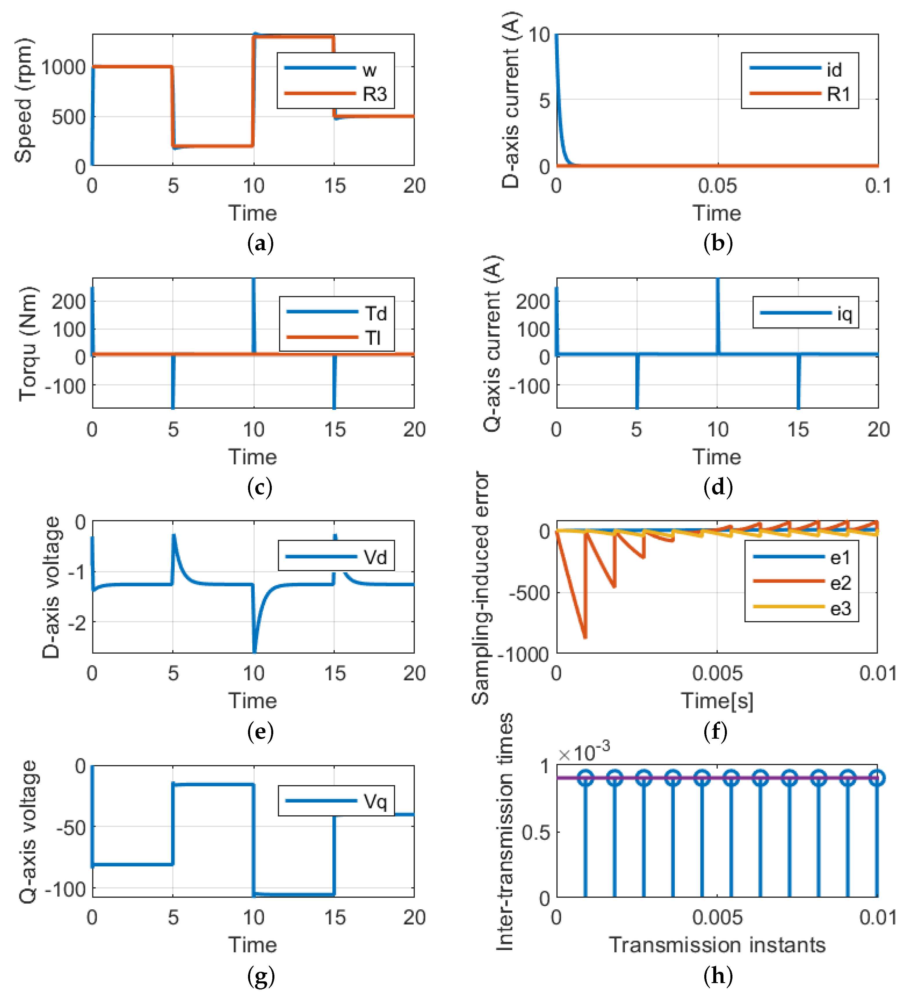
7.1. Closed Loop of Variable Speed and Constant Load Torque

The LQR, which is based on the HCT, is used to examine the dynamic response of the PMSM drive system under step changes in the reference speed and constant load torque. The load torque is fixed at 5N while the speed profile is illustrated in Figure 5a. With a quick response and a roughly 0% steady-state error, the LQR is able to maintain the actual speed on the reference value’s trajectory. To ensure the MTPA, the control method also keeps the actual value of the d-axis current at zero references as illustrated in Figure 5b. However, the reference speed changes the developed torque from the machine and equals the load torque, as shown in Figure 5c. The corresponding q-axis current used to satisfy the load torque is depicted in Figure 5d. Under this working case, the values of the dq-axis voltages are shown in Figure 5e, where it can be observed that these values vary to satisfy the required reference speed and torque. For better validation of the suggested control technique, the sampling-induced errors for the three states are also presented in Figure 5f, where it can be seen that the error goes to zero. Finally, Figure 5h presents the relationship between the transmission instant and the inter-transmission time.

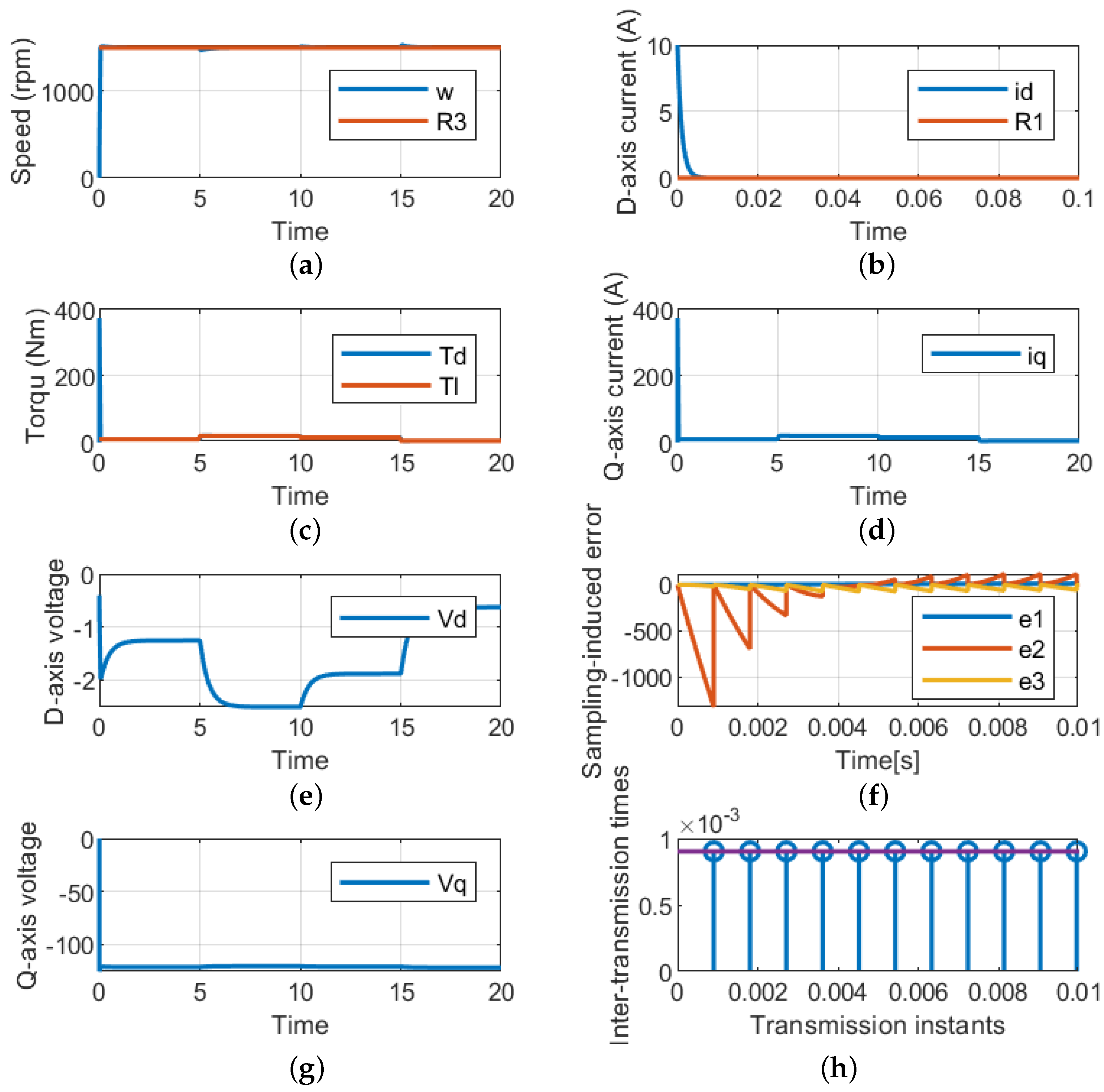
7.2. Closed Loop of Constant Speed and Variable Load Torque

This case is used to validate the LQR of the PMSM used in the EV under different loading conditions and fixed reference speeds. The reference speed is fixed at 1500 rpm; the control succeeded at regulating the actual speed by tracking the reference speed, as indicated in Figure 6a for MATLAB/Simulink. Also, the control is capable of maintaining the d-axis current and satisfying the load torque, as indicated in Figure 6b,c. As the q-axis is related to the load torque, its dynamic response is similar to the load torque, as shown in Figure 6d,e. Meanwhile, the input dq-axis voltage is shown in Figure 6g. Finally, the sampling errors and the periodic sampling times are shown in Figure 6f,h, respectively.

7.3. Closed Loop of Variable Speed and Variable Load Torque

This case is used to validate the LQR of the PMSM used in the EV under different loading conditions and variable reference speeds, as shown in Figure 7a and Figure 7c, respectively. Also, the control is capable of maintaining the d-axis current and satisfying the load torque, as indicated in Figure 7b,d. As the q-axis is related to the load torque, its dynamic response is similar to the load torque, as shown in Figure 6d,e. Meanwhile, the input dq-axis voltage is shown in Figure 6g. Finally, the sampling errors and the periodic sampling times are shown in Figure 6f and Figure 6h, respectively.

7.4. Simulation Comparison

To further illustrate the advantage of the proposed approach, comparisons with [30,31,32,33] on the estimated sampling period for PMSM are presented in Table 2.Note that since the derived upper bound of the sampling period depends on the PMSM parameters, we calculated this bound at the given values in each corresponding work of [30,31,32,33]. The results clearly show that the proposed approach performs in a superior manner when reducing the sampling frequency while maintaining closed-loop stability.

8. Conclusions

The robust stabilization of the PMSM using nonlinear state feedback control was considered. In particular, the design approach was based on the assumption that the state measurement is analog while the controller is digital, which is the case in most practical systems. This implementation scheme was carried on within the framework of a sampled-data system in which both the synthesis of the feedback law and stabilizing sampling frequency need to be considered. To solve this problem, the emulation approach was employed, such that the design process was divided into two sequential steps: the control design in continuous time and the derivation of the stabilizing sampling period. For the control design, the feedback linearization approach was used to count the nonlinear dynamic terms of the PMSM model. Moreover, the linearized system was handled by a linear quadratic regulator to optimally allocate the closed-loop poles according to the desired performance criteria. In addition, the LQR technique was enriched by an integral action to cope with existing uncertainties due to load/speed variations. Then, after the PMSM was robustly stabilized in continuous time, an upper bound of the maximally allowable transmission interval was derived to determine the minimum stabilizing sampling frequency. Since sampled-data systems naturally exhibit both continuous-time dynamics and discrete transitions, the overall system has been modeled as a hybrid dynamical system, which is a more intuitive approach used to capture the mixed dynamic behaviors. The conditions required to apply the technique included the feasibility of a linear matrix inequality, which provides a systematic methodology for the user to check the required conditions. The closed-loop stability was carried out using appropriate hybrid Lyapunov functions. The effectiveness of the approach was examined on a dynamic model of the PMSM under different operating conditions. Simulation results show that the approach is robust against speed and load variations and the derived sampling frequency is accurate and less conservative than the traditional assumption of the Nyquist sampling rule. Furthermore, the methodology was tested on a hardware-in-the-loop setup and the results are consistent with the analysis and simulation findings.
This work can be extended in different directions. The proposed approach opens up the door for more interesting implementation scenarios, such as event-triggered controls and self-triggered controls. Future work will include the stability analysis of the overall dynamics of the electric vehicle under different driving conditions.

Author Contributions

Conceptualization, M.F.E.; methodology, M.A.; formal analysis, D.A.; investigation, D.A.; simulation, M.A.; writing—original draft preparation, M.F.E.; writing—review and editing, D.A. All authors have read and agreed to the published version of the manuscript.

Funding

This work was supported by Prince Sultan University, Riyadh, Saudi Arabia.

Data Availability Statement

Not applicable.

Acknowledgments

The authors would like to acknowledge the support of Prince Sultan University for paying the article processing charges (APCs) of this publication.

Conflicts of Interest

The authors declare no conflict of interest.

References

  1. Adib, A.; Afridi, K.K.; Amirabadi, M.; Fateh, F.; Ferdowsi, M.; Lehman, B.; Lewis, L.H.; Mirafzal, B.; Saeedifard, M.; Shadmand, M.B.; et al. E-Mobility-Advancements and Challenges. IEEE Access 2019, 7, 165226–165240. [Google Scholar] [CrossRef]
  2. Sanguesa, J.; Torres-Sanz, V.; Garrido, P.; Martinez, F.; Marquez-Barja, J. A Review on Electric Vehicles: Technologies and Challenges. Smart Cities 2021, 4, 372–404. [Google Scholar] [CrossRef]
  3. Kumar, R.; Pachauri, R.; Badoni, P.; Bharadwaj, D.; Mittal, U.; Bisht, A. Investigation on parallel hybrid electric bicycle along with issuer management system for mountainous region. J. Clean. Prod. 2022, 362, 132430. [Google Scholar] [CrossRef]
  4. Kumar, R.; Ahuja, R.; Saxena, M.; Kumar, A. Automotive Power Window Communication with DTC Algorithm and Hardware-in-the Loop Testing. Wirel. Pers. Commun. 2020, 114, 3351–3366. [Google Scholar] [CrossRef]
  5. El-Refaie, A.M. Motors/generators for traction/propulsion applications: A review. IEEE Veh. Technol. Mag. 2013, 8, 90–99. [Google Scholar] [CrossRef]
  6. Liao, G.; Zhang, W.; Cai, C. Research on a PMSM control strategy for electric vehicles. Adv. Mech. Eng. 2021, 13, 16878140211051462. [Google Scholar] [CrossRef]
  7. Maroti, P.K.; Padmanaban, S.; Bhaskar, M.S.; Ramachandaramurthy, V.K.; Blaabjerg, F. The state-of-the-art of power electronics converters configurations in electric vehicle technologies. Power Electron. Devices Components 2022, 1, 100001. [Google Scholar] [CrossRef]
  8. Rangarajan, S.S.; Sunddararaj, S.P.; Sudhakar, A.; Shiva, C.K.; Subramaniam, U.; Collins, E.R.; Senjyu, T. Lithium-Ion Batterie-The Crux of Electric Vehicles with Opportunities and Challenges. Clean Technol. 2022, 4, 908–930. [Google Scholar] [CrossRef]
  9. Lee, K.; Ahmed, S.; Lukic, S.M. Universal Restart Strategy for High-Inertia Scalar-Controlled PMSM Drives. IEEE Trans. Ind. Appl. 2016, 52, 4001–4009. [Google Scholar] [CrossRef]
  10. Rachev, E.; Petrov, V. Reducing the transient in switching from scalar to field oriented control for smooth ramp start of a permanent magnet synchronous motor. In Proceedings of the 2019 11th Electrical Engineering Faculty Conference (BulEF), Varna, Bulgaria, 11–14 September 2019; pp. 1–4. [Google Scholar] [CrossRef]
  11. Subramaniam, U.; Reddy, K.S.; Kaliyaperumal, D.; Sailaja, V.; Bhargavi, P.; Likhith, S. A MIMO-ANFIS-Controlled Solar-Fuel-Cell-Based Switched Capacitor Z-Source Converter for an Off-Board EV Charger. Energies 2023, 16, 1693. [Google Scholar] [CrossRef]
  12. Alzayed, M.; Chaoui, H. Efficient Simplified Current Sensorless Dynamic Direct Voltage MTPA of Interior PMSM for Electric Vehicles Operation. IEEE Trans. Veh. Technol. 2022, 71, 12701–12710. [Google Scholar] [CrossRef]
  13. Tang, M.; Chen, Y.; Yang, T. Field Weakening Design for a High Speed Nine-phase Permanent Magnet Synchronous Machine in More Electric Aircraft. In Proceedings of the 2022 IEEE Transportation Electrification Conference & Expo (ITEC), Anaheim, CA, USA, 15–17 June 2022; pp. 1093–1096. [Google Scholar] [CrossRef]
  14. Koç, M. Unified Field Oriented Controlled Drive System for All Types of the PMSMs Considering System Nonlinearities. IEEE Access 2022, 10, 56773–56784. [Google Scholar] [CrossRef]
  15. Petkar, S.G.; Thippiripati, V.K. A Novel Duty Controlled DTC of a Surface PMSM Drive With Reduced Torque and Flux Ripples. IEEE Trans. Ind. Electron. 2022, 70, 3373–3383. [Google Scholar] [CrossRef]
  16. Sharkawy, A.; Othman, M.; Khalil, A. A robust fuzzy tracking control scheme for robotic manipulators with experimental verification. Intell. Control Autom. 2010, 2, 100–111. [Google Scholar] [CrossRef]
  17. Nasr, A.; Gu, C.; Wang, X.; Buticchi, G.; Bozhko, S.; Gerada, C. Torque-Performance Improvement for Direct Torque-Controlled PMSM Drives Based on Duty-Ratio Regulation. IEEE Trans. Power Electron. 2022, 37, 749–760. [Google Scholar] [CrossRef]
  18. Wang, X.; Wang, Z.; Xu, Z.; Cheng, M.; Hu, Y. Optimization of Torque Tracking Performance for Direct-Torque-Controlled PMSM Drives With Composite Torque Regulator. IEEE Trans. Ind. Electron. 2020, 67, 10095–10108. [Google Scholar] [CrossRef]
  19. Niu, F.; Wang, B.; Babel, A.S.; Li, K.; Strangas, E.G. Comparative Evaluation of Direct Torque Control Strategies for Permanent Magnet Synchronous Machines. IEEE Trans. Power Electron. 2016, 31, 1408–1424. [Google Scholar] [CrossRef]
  20. Sain, C.; Banerjee, A.; Biswas, P.; Azar, A.; Babu, T.S. Design and optimisation of a fuzzy-PI controlled modified inverter-based PMSM drive employed in a light weight electric vehicle. Int. J. Autom. Control 2022, 16, 459. [Google Scholar] [CrossRef]
  21. Pilla, R.; Gorripotu, T.; Azar, A. Tuning of extended Kalman filter using grey wolf optimisation for speed control of permanent magnet synchronous motor drive. Int. J. Autom. Control 2021, 15, 563. [Google Scholar] [CrossRef]
  22. Abdelrahim, M.; Mabrok, M.A.; Darwish, M.A.H. Networked control design for an engine throttle valve system. Int. J. Control 2023, 96, 1736–1743. [Google Scholar] [CrossRef]
  23. Gu, M.; Yang, Y.; Fan, M.; Xiao, Y.; Liu, P.; Zhang, X.; Yang, H.; Rodriguez, J. Finite Control Set Model Predictive Torque Control with Reduced Computation Burden for PMSM Based on Discrete Space Vector Modulation. IEEE Trans. Energy Convers. 2022, 38, 703–712. [Google Scholar] [CrossRef]
  24. Elmorshedy, M.F.; Xu, W.; El-Sousy, F.F.M.; Islam, R.; Ahmed, A.A. Recent achievements in model predictive control techniques for industrial motor: A Comprehensive state-of-the-art. IEEE Access 2021, 9, 58170–58191. [Google Scholar] [CrossRef]
  25. Murali, A.; Wahab, R.; Gade, C.; Annamalai, C.; Subramaniam, U. Assessing Finite Control Set Model Predictive Speed Controlled PMSM Performance for Deployment in Electric Vehicles. World Electr. Veh. J. 2021, 12, 41. [Google Scholar] [CrossRef]
  26. Diab, A.; Yeoh, S.; Bozhko, S.; Gerada, C.; Galea, M. Enhanced Active Disturbance Rejection Current Controller for Permanent Magnet Synchronous Machines Operated at Low Sampling Time Ratio. IEEE J. Emerg. Sel. Top. Ind. Electron. 2022, 3, 230–241. [Google Scholar]
  27. Mishra, I.; Tripathi, R.; Hanamoto, T. Synchronization and Sampling Time Analysis of Feedback Loop for FPGA-Based PMSM Drive System. Electronics 2020, 9, 1906. [Google Scholar] [CrossRef]
  28. Sakthivel, R.; Santra, S.; Kaviarasan, B.; Park, J. Finite-time sampled-data control of permanent magnet synchronous motor systems. Nonlinear Dyn. 2016, 86, 2081–2092. [Google Scholar] [CrossRef]
  29. Yu, Y.; Shen, Y.; Liu, Y. Sampled-data based output tracking H control for PMSM servo system. In Proceedings of the 2017 Chinese Automation Congress (CAC), Jinan, China, 20–22 October 2017; pp. 5521–5525. [Google Scholar]
  30. Khanchoul, M.; Hilairet, M.; Normand-Cyrot, D. IDA-PBC under sampling for torque control of the PMSM. IFAC Proc. Vol. 2013, 46, 15–20. [Google Scholar] [CrossRef]
  31. Vadivel, R.; Njitacke, Z.T.; Shanmugam, L.; Hammachukiattikul, P.; Gunasekaran, N. Dynamical analysis and reachable set estimation of T-S fuzzy system with permanent magnet synchronous motor. Commun. Nonlinear Sci. Numer. Simul. 2023, 125, 107407. [Google Scholar] [CrossRef]
  32. Dominguez, J.; Navarrete, A.; Meza, M.; Loukianov, A.G.; Canedo, J. Digital Sliding-Mode Sensorless Control for Surface-Mounted PMSM. IEEE Trans. Ind. Informatics 2014, 10, 137–151. [Google Scholar] [CrossRef]
  33. Rizvi, S.; Memon, A. An extended observer-based robust nonlinear speed sensorless controller for a PMSM. Int. J. Control 2019, 92, 2123–2135. [Google Scholar] [CrossRef]
  34. Carnevale, D.; Teel, A.; Nešić, D. A Lyapunov proof of an improved maximum allowable transfer interval for networked control systems. IEEE Trans. Autom. Control 2007, 52, 892–897. [Google Scholar]
  35. Nešić, D.; Teel, A.; Carnevale, D. Explicit Computation of the Sampling Period in Emulation of Controllers for Nonlinear Sampled-Data Systems. IEEE Trans. Autom. Control 2009, 54, 619–624. [Google Scholar] [CrossRef]
  36. Goebel, R.; Sanfelice, R.; Teel, A. Hybrid Dynamical Systems: Modeling, Stability, and Robustness; Princeton University Press: Princeton, NJ, USA, 2012. [Google Scholar]
  37. Abdelrahim, M.; Postoyan, R.; Daafouz, J. Event-triggered control of nonlinear singularly perturbed systems based only on the slow dynamics. In Proceedings of the 9th IFAC Symposium on Nonlinear Control Systems The International Federation of Automatic Control, Toulouse, France, 4–6 September 2013; pp. 347–352. [Google Scholar]
  38. Abdelrahim, M.; Postoyan, R.; Daafouz, J.; Nešić, D. Event-triggered dynamic feedback controllers for nonlinear systems with asynchronous transmissions. In Proceedings of the 54th IEEE Conference on Decision and Control, Osaka, Japan, 15–18 December 2015; pp. 5494–5499. [Google Scholar]
  39. Jlassi, I.; Marques Cardoso, A.J. Enhanced and Computationally Efficient Model Predictive Flux and Power Control of PMSG Drives for Wind Turbine Applications. IEEE Trans. Ind. Electron. 2021, 68, 6574–6583. [Google Scholar] [CrossRef]
  40. Attaianese, C.; DÁrpino, M.; Monaco, M.D.; Di Noia, L.P. Modeling and Detection of Phase Current Sensor Gain Faults in PMSM Drives. IEEE Access 2022, 10, 80106–80118. [Google Scholar] [CrossRef]
  41. Elmorshedy, M.F.o. Improved Standalone PMSG based Wind-Generating System Using MPPT and MRAS for Speed Estimation. In Proceedings of the 2021 IEEE 4th International Conference on Computing, Power and Communication Technologies (GUCON), Kuala Lumpur, Malaysia, 24–26 September 2021; pp. 1–6. [Google Scholar] [CrossRef]
  42. Bacha, S.; Munteanu, I.; Bratcu, A. Power Electronic Converters Modeling and Control. In Advanced Textbooks in Control and Signal Processing; Springer: London, UK, 2014; Volume 454. [Google Scholar]
Figure 1. Equivalent circuit of the PMSM.
Processes 11 02370 g001
Figure 2. Block diagram of the adopted PMSM drive system using the LQR.
Processes 11 02370 g002
Figure 3. Block diagram of the HIL setup.
Processes 11 02370 g003
Figure 4. Photograph of the setup based on typhoon HIL 602+ and HIL 402.
Processes 11 02370 g004
Figure 5. Performance of the proposed technique under variable speeds and constant load torques. (a) Rotating speed. (b) d-axis current. (c) Load and developed torques. (d) q-axis current. (e) d-axis voltage (g) dq-axis voltages. (f) Sampling error. (h) Periodic sampling times.
Processes 11 02370 g005
Figure 6. Performance of the suggested LQR control technique for variable speeds and constant load torques. (a) Rotating speed. (b) d-axis current. (c) Load and developed torques. (d) q-axis current. (e) d-axis voltage (g) dq-axis voltages. (f) Sampling error. (h) Periodic sampling times.
Processes 11 02370 g006
Figure 7. Performance of the suggested LQR control technique for variable speeds and load torques. (a) Rotating speed. (b) d-axis current. (c) Load and developed torques. (d) q-axis current. (e) d-axis voltage (g) dq-axis voltages. (f) Sampling error. (h) Periodic sampling times.
Processes 11 02370 g007
Table 1. Parameters of the PMSM.
ParameterValue
Power1000 W
Number of phases3
Maximum speed3000 rpm
Number of poles4
Resistance0.0125 Ω
Inductance0.1025 mH
Inertia0.0045 NMs 2
Coefficient of friction0.0021 Nm s rad 1
Back emf0.025 V s rad 1
Table 2. Comparisons with [30,31,32,33] on the derived sampling period for PMSM.
Result[32][33][30][31]
Largest sampling period by the result0.2 ms1 ms3 ms10 ms
Largest sampling period by our technique8.9 ms2.2 ms4.2 ms15.74
Disclaimer/Publisher’s Note: The statements, opinions and data contained in all publications are solely those of the individual author(s) and contributor(s) and not of MDPI and/or the editor(s). MDPI and/or the editor(s) disclaim responsibility for any injury to people or property resulting from any ideas, methods, instructions or products referred to in the content.

